EP3247949B1 - Turbo fan and air conditioner having the same - Google Patents
Turbo fan and air conditioner having the same Download PDFInfo
- Publication number
- EP3247949B1 EP3247949B1 EP16803726.5A EP16803726A EP3247949B1 EP 3247949 B1 EP3247949 B1 EP 3247949B1 EP 16803726 A EP16803726 A EP 16803726A EP 3247949 B1 EP3247949 B1 EP 3247949B1
- Authority
- EP
- European Patent Office
- Prior art keywords
- wing
- side plate
- bended
- main plate
- wings
- Prior art date
- Legal status (The legal status is an assumption and is not a legal conclusion. Google has not performed a legal analysis and makes no representation as to the accuracy of the status listed.)
- Active
Links
Images


Classifications
-
- F—MECHANICAL ENGINEERING; LIGHTING; HEATING; WEAPONS; BLASTING
- F04—POSITIVE - DISPLACEMENT MACHINES FOR LIQUIDS; PUMPS FOR LIQUIDS OR ELASTIC FLUIDS
- F04D—NON-POSITIVE-DISPLACEMENT PUMPS
- F04D29/00—Details, component parts, or accessories
- F04D29/26—Rotors specially for elastic fluids
- F04D29/28—Rotors specially for elastic fluids for centrifugal or helico-centrifugal pumps for radial-flow or helico-centrifugal pumps
- F04D29/281—Rotors specially for elastic fluids for centrifugal or helico-centrifugal pumps for radial-flow or helico-centrifugal pumps for fans or blowers
-
- F—MECHANICAL ENGINEERING; LIGHTING; HEATING; WEAPONS; BLASTING
- F04—POSITIVE - DISPLACEMENT MACHINES FOR LIQUIDS; PUMPS FOR LIQUIDS OR ELASTIC FLUIDS
- F04D—NON-POSITIVE-DISPLACEMENT PUMPS
- F04D25/00—Pumping installations or systems
- F04D25/02—Units comprising pumps and their driving means
- F04D25/08—Units comprising pumps and their driving means the working fluid being air, e.g. for ventilation
-
- F—MECHANICAL ENGINEERING; LIGHTING; HEATING; WEAPONS; BLASTING
- F04—POSITIVE - DISPLACEMENT MACHINES FOR LIQUIDS; PUMPS FOR LIQUIDS OR ELASTIC FLUIDS
- F04D—NON-POSITIVE-DISPLACEMENT PUMPS
- F04D29/00—Details, component parts, or accessories
- F04D29/002—Details, component parts, or accessories especially adapted for elastic fluid pumps
-
- F—MECHANICAL ENGINEERING; LIGHTING; HEATING; WEAPONS; BLASTING
- F04—POSITIVE - DISPLACEMENT MACHINES FOR LIQUIDS; PUMPS FOR LIQUIDS OR ELASTIC FLUIDS
- F04D—NON-POSITIVE-DISPLACEMENT PUMPS
- F04D29/00—Details, component parts, or accessories
- F04D29/26—Rotors specially for elastic fluids
- F04D29/28—Rotors specially for elastic fluids for centrifugal or helico-centrifugal pumps for radial-flow or helico-centrifugal pumps
- F04D29/30—Vanes
-
- F—MECHANICAL ENGINEERING; LIGHTING; HEATING; WEAPONS; BLASTING
- F04—POSITIVE - DISPLACEMENT MACHINES FOR LIQUIDS; PUMPS FOR LIQUIDS OR ELASTIC FLUIDS
- F04D—NON-POSITIVE-DISPLACEMENT PUMPS
- F04D29/00—Details, component parts, or accessories
- F04D29/66—Combating cavitation, whirls, noise, vibration or the like; Balancing
- F04D29/68—Combating cavitation, whirls, noise, vibration or the like; Balancing by influencing boundary layers
- F04D29/681—Combating cavitation, whirls, noise, vibration or the like; Balancing by influencing boundary layers especially adapted for elastic fluid pumps
-
- F—MECHANICAL ENGINEERING; LIGHTING; HEATING; WEAPONS; BLASTING
- F24—HEATING; RANGES; VENTILATING
- F24F—AIR-CONDITIONING; AIR-HUMIDIFICATION; VENTILATION; USE OF AIR CURRENTS FOR SCREENING
- F24F1/00—Room units for air-conditioning, e.g. separate or self-contained units or units receiving primary air from a central station
- F24F1/0007—Indoor units, e.g. fan coil units
- F24F1/0018—Indoor units, e.g. fan coil units characterised by fans
- F24F1/0022—Centrifugal or radial fans
-
- F—MECHANICAL ENGINEERING; LIGHTING; HEATING; WEAPONS; BLASTING
- F05—INDEXING SCHEMES RELATING TO ENGINES OR PUMPS IN VARIOUS SUBCLASSES OF CLASSES F01-F04
- F05D—INDEXING SCHEME FOR ASPECTS RELATING TO NON-POSITIVE-DISPLACEMENT MACHINES OR ENGINES, GAS-TURBINES OR JET-PROPULSION PLANTS
- F05D2250/00—Geometry
- F05D2250/70—Shape
- F05D2250/71—Shape curved
Definitions
- Embodiments of the present disclosure relate to a turbo fan and an air conditioner having the same.
- a turbo fan is used in a ventilation device including an air conditioner and the like, and includes a main plate of a disc shape mounted at a rotational shaft of a motor, a side plate provided to be spaced apart from the main plate in an axial direction of the rotational shaft, and a plurality of wings fixed between the main plate and the side plate and provided in a circumferential direction of the main plate.
- European patent application EP 2,835,539 and Japanese patent applications JP 2005 282567 and JP 2010 174671 show examples of such turbo fans used in ventilation devices
- An opening for suctioning air is provided at a center portion of the side plate, and air suctioned through the opening is discharged through an empty area between the side plate and the main plate.
- each wing of the turbo fan is bended in a reverse direction against a rotational direction of the wing in an outermost diameter direction of a leading edge thereof, and such a bended shape may promote a reattachment of an air separation (escape) which occurs at a negative pressure surface.
- each wing of the turbo fan since a bended portion of each wing of the turbo fan is located at the contact portion between the side plate and the leading edge of each wing and each wing is not bended toward a downstream side from the contact portion, there is a problem in which an air separation occurring at the contact portion between the side plate and the leading edge of each wing is not reattached.
- turbo fan capable of implementing high efficiency of ventilation and reducing noise thereof by providing a bended portion being bended in a reverse direction against a rotational direction of a wing between a leading edge and a trailing edge thereof to reattach an air separation generated at a negative pressure surface of the wing, and a ventilation device having the same.
- a turbo fan as defined in claim 1 includes a main plate having a disc shape and on which a rotational shaft is mounted, a side plate provided to be separated from the main plate along an axial direction of the rotational shaft and having a ring shape with an opening at a center portion of the side plate, and a plurality of wings fixed between the main plate and the side plate along a circumferential direction of the main plate, wherein each wing of the plurality of wings includes a leading edge having a portion coming in contact with the side plate, a trailing edge, and wherein a cross-section of each wing in a plane perpendicular to the axis of rotation comprises an airfoil with a camber line extending between the leading and trailing edges, the cross-section comprising a bended portion, which is bended in a reverse direction against a rotational direction of the wing, such that, the camber line comprises a front end having a first curvature between the leading edge and the bended portion,
- the leading edge has a main plate contact portion at which the leading edge and the main plate come in contact with each other , the main plate contact portion having a first curved shape in which a first curvature variation is small, the leading edge has a side plate contact portion at which the leading edge and the side plate come in contact with each other , the side plate contact portion having a second curved shape in which a second curvature variation is small, and the bended portion may be between the main plate contact portion and the side plate contact portion.
- the trailing edge may be provided to have a straight line shape inclined toward an axial direction of the turbo fan, or a curve shape waved in an axial direction.
- a hub at which the rotational shaft is mounted may be provided at the main plate, and the main plate and the side plate may be molded with a resin material.
- Air may be suctioned through the opening provided in the side plate, and the air suctioned through the opening may be discharged through an empty area between the side plate and the main plate.
- the side plate may be provided to have an outer diameter equal to that of the main plate, and to have a shape of which an inner diameter is decreased as it goes toward an inner side in a direction away from the main plate.
- Each wing of the plurality of wings may be configured to have a convexly curved shape in the rotational direction of the wing, and to include a positive pressure surface which is an outer circumferential surface in the rotational direction of the wing and a negative pressure surface which is a rear surface opposite to the positive pressure surface.
- the main plate may include a faceplate part facing the side plate, and the leading edge and the trailing edge of each wing of the plurality of wings may be formed from the faceplate part to an inner circumferential surface of the side plate.
- a distance between a main plate contact portion at which the leading edge and the main plate come in contact with each other and the rotational shaft may be less than a radius of the opening, and a distance between a side plate contact portion at which the leading edge and the side plate come in contact with each other and the rotational shaft may be greater than the radius of the opening.
- the trailing edge may be fixed to an outer edge portion of the main plate and an outer edge portion of the side plate.
- the main plate contact portion and the side plate contact portion may be provided to have a curved shape having no bended portion, and the bended portion may be provided between the main plate contact portion and the side plate contact portion.
- each of the positive pressure surface of the wing and the negative pressure surface thereof may be bended in a reverse direction against the rotational direction of the wing at the bended portion.
- the positive pressure surface and the negative pressure surface may be provided to have a front end curvature being constant from the leading edge to the bended portion and a rear end curvature being constant from the bended portion to the trailing edge, and the front end curvature and the rear end curvature may be provided to have curvatures different from each other.
- the positive pressure surface and the negative pressure surface may be provided to have a front end curvature being continuously varied from the leading edge to the bended portion and a rear end curvature being continuously varied from the bended portion to the trailing edge, and the front end curvature and the rear end curvature may be provided to have curvatures different from each other.
- the wing may be bended in the reverse direction against the rotational direction of the wing in a range of the height h1 satisfying 0.2 ⁇ h1/h0 ⁇ 0.8.
- a diameter direction length Ra from the rotational shaft to the leading edge, a diameter direction length Rb from the rotational shaft to the trailing edge, and a diameter direction length Rc from the rotational shaft to the bended portion may satisfy 0.3 ⁇ (Rc-Ra)/(Rb-Ra) ⁇ 0.7.
- a wing angle ⁇ a formed between an extended direction of the wing at the leading edge and a tangential direction of a rotational orbit of the leading edge, and a wing angle ⁇ c formed between an extended direction of the wing at the bended portion and a tangential direction of a rotational orbit of the bended portion may satisfy 0.6 ⁇ ⁇ c/ ⁇ a ⁇ 0.9.
- a ventilation device includes a turbo fan including, a main plate having a disc shape and on which a rotational shaft is mounted, a side plate provided to be separated from the main plate along an axial direction of the rotational shaft and having a ring shape with an opening at a center portion of the side plate, and a plurality of wings fixed between the main plate and the side plate along a circumferential direction of the main plate, wherein each wing of the plurality of wings includes a leading edge having a portion coming in contact with the side plate, a trailing edge, and a bended portion, which is bended in a reverse direction against a rotational direction of the wing between the portion of the leading edge of the wing coming in contact with the side plate and the trailing edge of the wing.
- the leading edge has a main plate contact portion at which the leading edge and the main plate come in contact with each other , the main plate contact portion having a first curved shape in which a first curvature variation is small, the leading edge has a side plate contact portion at which the leading edge and the side plate come in contact with each other , the side plate contact portion having a second curved shape in which a second curvature variation is small, and the bended portion may be between the main plate contact portion and the side plate contact portion.
- a turbo fan includes a main plate having a disc shape and on which a rotational shaft is mounted, a side plate provided to be separated from the main plate along an axial direction of the rotational shaft and having a ring shape with an opening at a center portion of the side plate, and a plurality of wings fixed between the main plate and the side plate along a circumferential direction of the main plate, wherein each wing of the plurality of wings includes a leading edge having a portion coming in contact with the side plate, a trailing edge, and a bended portion, which is bended in a reverse direction against a rotational direction of the wing between the portion of the leading edge of the wing coming in contact with the side plate and the trailing edge of the wing.
- the leading edge has a main plate contact portion at which the leading edge and the main plate come in contact with each other , the main plate contact portion having a first curved shape in which a first curvature variation is small, the leading edge has a side plate contact portion at which the leading edge and the side plate come in contact with each other, the side plate contact portion having a second curved shape in which a second curvature variation is small, and the bended portion is between the main plate contact portion and side plate contact portion.
- high efficiency of ventilation and low noise may be implemented and work efficiency at the positive pressure surface of the wing may be improved.
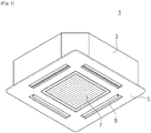
- a turbo fan 100 according to the present embodiment is used in a ventilation device, for example, an air conditioner 1 and the like.
- the air conditioner 1 is fit in and installed on a ceiling (not shown) through an opening thereof, and includes a main body 3 of a polyhedral box shape of which a lower surface is opened, and a ceiling panel 5 mounted at a lower end of the main body 3.
- the turbo fan 100 is provided inside the main body 3, a suction inlet 7 through which outside air is suctioned is provided at a center portion of the ceiling panel 5, and a discharge outlet 9 through which air is discharged is provided at outer side peripheries of the suction inlet 7.
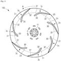
- the turbo fan 100 includes a main plate 10 of a disc shape at which a rotational shaft C of a motor (not shown) is mounted, a side plate 20 provided in a ring shape when viewed from a plane at an opposite position spaced apart from the main plate 10 toward an axial direction of the rotational shaft C, and a plurality of wings 30 provided between the main plate 10 and the side plate 20 to be fixed therebetween.
- the main plate 10, the side plate 20, and each of the wings 30 of the turbo fan 100 are integrally rotated around the rotational shaft C, and the turbo fan 100 suctions air along the axial direction through an opening O formed at the side plate 20 and discharges the suctioned air along a diameter direction between the main plate 10 and the side plate 20.
- the main plate 10 has a hub that is a fixing unit 11 at which the rotational shaft C of the motor is mounted, and may be configured with, for example, a resin product fabricated to align a central axis of the hub with the rotational shaft C.
- the side plate 20 is a so-called shroud (a cover ring) in which the opening O formed at the center portion thereof is provided as the suction inlet for suctioning air, and an empty area between outer edges of the side plate 20 and the main plate 10 is provided as the discharge outlet.
- shroud a cover ring
- the side plate 20 of the present embodiment may be configured with, for example, a resin product which is set to have an outer diameter the same as that of the main plate 10, has a shape bended in a direction away from the main plate 10 and an inner diameter which is decreased as it goes toward an inner side of the resin product, and is fabricated to align a center axis of the side plate 20 with the rotational shaft C.
- the side plate 20 is not limited to the shape described above, and it may be a flat plate of a ring shape when viewed from the plane, for example.
- the wing 30 is configured to be rotated around the rotational shaft C and also to have a convexly curved shape to a rotational direction R of the wing 30 to extrude air from a positive pressure surface 31, which is an outer circumferential surface of the rotational direction R, toward the diameter direction.
- each of the positive pressure surface 31 and a negative pressure surface 32 is herein convexly curved to the rotational direction R.
- the turbo fan 100 of the present embodiment includes a plurality of wings 30, for example, resin products, having a shape the same as each other, and each of the wings 30 is arranged along a circumferential direction in a regular interval centering on the rotational shaft C and also is fixed to the main plate 10 and the side plate 20 through, for example, laser fusion.
- a leading edge 3a and a trailing edge 3b of each wing 30 are formed from a faceplate part 12 of the main plate 10 facing the side plate 20 to an inner circumferential surface 21 thereof.
- a part of the leading edge 3a is installed at an inner side as compared to the opening O of the side plate 20, and in the present embodiment, a main plate contact portion P, which is a contact portion of the leading edge 3a and the main plate 10, is located at an inner side as compared to the opening O, and also a side plate contact portion Q, which is a contact portion of the leading edge 3a and the side plate 20, is located at an outer side as compared to the opening O.
- the trailing edge 3b is installed to be overlapped with the outer edges of the main plate 10 and the side plate 20. That is, the trailing edge 3b is fixed to an outer edge portion of the main plate 10 and an outer edge portion of the side plate 20.
- the wing 30 of the present embodiment is provided to have a shape which is more bended in the reverse direction against the rotational direction R of the wing 30 toward an outer diameter direction as compared to a leading edge outer end 35 of the leading edge 3a in an outermost diameter direction.
- each of the wings 30 is provided to have a shape bended in the reverse direction against the rotational direction R thereof between the leading edge 3a and the trailing edge 3b, and herein is more bended in the reverse direction against the rotational direction R of the wing 30 in the outer diameter direction as compared to the side plate contact portion Q which is the contact portion of the leading edge 3a and the side plate 20 as described above.
- each of the wings 30 includes a bended portion 3c at which a bending modulus is discontinuously varied between the leading edge 3a and the trailing edge 3b, and the positive pressure surface 31 and the negative pressure surface 32 are bended at the bended portion 3c in the reverse direction against the rotational direction R of each of the wings 30.
- the positive pressure surface 31 and the negative pressure surface 32 have a front end bending modulus, which is constant or continuously varied, from the leading edge 3a to the bended portion 3c and also a rear end bending modulus, which is constant or continuously varied, from the bended portion 3c to the trailing edge 3b, and the front end bending modulus and the rear end bending modulus are configured to have bending moduli or variation rates different from each other.
- a central line (so-called as a camber line) passing center points of the positive pressure surface 31 and the negative pressure surface 32 is bent in the reverse direction against the rotational direction R of the wing 30 at the bended portion 3c to vary a bending modulus of the central line before and after the bended portion 3c.
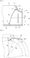
- the bended portion 3c is located at the outer diameter direction as compared to the opening O of the side plate 20 when viewed from the plane, and herein, as shown in FIG. 5 , when a diameter direction length Ra is a length from the rotational shaft C to the leading edge 3a, a diameter direction length Rb is a length from the rotational shaft C to the trailing edge 3b, and a diameter direction length Rc is a length from the rotational shaft C to the bended portion 3c in a cross section perpendicular to the axial direction, the bended portion 3c is installed to satisfy Equation 1 as follows. 0.3 ⁇ Rc ⁇ Ra / Rb ⁇ Ra ⁇ 0.7
- a wing angle ⁇ a and a wing angle ⁇ c of each of the wings 30 are configured to satisfy Equation 2 as follows, wherein the wing angle ⁇ a is an angle formed between an extended direction of the wing 30 at the leading edge 3a and a tangential direction of a rotational orbit at the leading edge 3a, and the wing angle ⁇ c is an angle formed between an extended direction of the wing 30 at the bended portion 3c and a tangential direction of a rotational orbit at the bended portion 3c.
- Equation 2 Equation 2 as follows, wherein the wing angle ⁇ a is an angle formed between an extended direction of the wing 30 at the leading edge 3a and a tangential direction of a rotational orbit at the leading edge 3a, and the wing angle ⁇ c is an angle formed between an extended direction of the wing 30 at the bended portion 3c and a tangential direction of a rotational orbit at the bended portion 3c.
- the bended portion 3c described above is formed only between a main plate lateral end 33 of each of the wings 30 and a side plate lateral end 34 thereof instead of being formed at the main plate lateral end 33 and the side plate lateral end 34.
- the main plate contact portion P coming in contact with the main plate 10 and the side plate contact portion Q coming in contact with the side plate 20 are not bended at all to form a curved shape having a less curvature variation, and, as shown in FIGS. 2 and 7 , a predetermined section along the axial direction between the main plate contact portion P and the side plate contact portion Q is provided as the bended portion 3c of the bended shape having a large curvature variation in the reverse direction against the rotational direction R of the wing 30.
- each of the wings 30 is bended in a reverse direction against a rotational direction in a range of the height length h1 satisfying Equation 3 as follows. 0.2 ⁇ h 1 / h 0 ⁇ 0.8
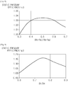
- FIG. 8 a ratio variation between a static pressure efficiency and a reference static pressure efficiency ⁇ 0 is shown in FIG. 8 .
- a graph shown in FIG. 8 represents a ratio of the static pressure efficiency when the reference static pressure efficiency ⁇ 0 is the static pressure efficiency in a case that (Rc-Ra)/(Rb-Ra) is 0.3.
- FIG. 9 a ratio variation between a static pressure efficiency and a reference static pressure efficiency ⁇ b is shown in FIG. 9 .
- a graph shown in FIG. 9 represents a ratio of the static pressure efficiency when the reference static pressure efficiency ⁇ b is the static pressure efficiency in a case that ⁇ c/ ⁇ a is 0.6.
- each of the wings 30 has been more bended in the reverse direction against the rotational direction R of the wing 30 toward the outer diameter direction as compared to the leading edge outer end of the leading edge 3a located in the outermost diameter direction, and the bended portion 3c is located more outward in the outer diameter direction as compared to the side plate contact portion Q at which the leading edge 3a and the side plate 20 come in contact with each other, so that, as shown in FIG. 10 , air may be reattached at the negative pressure surface 32 to a downstream side as compared to the bended portion 3c of each of the wings 30 to implement high efficiency and low noise of ventilation.
- each of the negative pressure surface 32 of the wing 30 and the positive pressure surface 31 thereof is more bended in the reverse direction toward the outer diameter direction as compared to the leading edge outer end 35, so that the air being separated is reattached to the negative pressure surface 32 of the wing 30 and also a boost performance at the positive pressure surface 31 is improved, thereby improving work efficiency of each of the wings 30.
- the main plate lateral end 33 and the side plate lateral end 34 of each of the wings 30 are not bended, so that a stress concentration generated at the main plate contact portion P at which each of the wings 30 and the main plate 10 come in contact with each other or the side plate contact portion Q at which each of the wings 30 and the side plate 20 come in contact with each other may be reduced and a mechanical strength of the turbo fan 100 with respect to a centrifugal force may be secured upon being rotated.
- main plate 10 the side plate 20, and each of the wings 30 are the resin products so that a weight of turbo fan 100 may be lightened.
- a trailing edge 41 of a wing 40 may be provided to have a straight line shape inclined toward an axial direction, or, as shown in FIG. 12 , a trailing edge 51 of a wing 50 may be provided to have a curve shape waved in an axial direction.
- the wings 40 and 50 shown in FIGS. 11 and 12 are adjustable in a wind direction according to a specification of the turbo fan 100, and are the same as the wing 30 shown in FIG. 2 except the shape of the trailing edge 3b thereof and also have effectiveness identical to that of the wing 30.
- the main plate contact portion P at which the leading edge 3a and the main plate 10 come in contact with each other is installed at the inner side as compared to the opening O of the side plate 20 when viewed from the plane, it may be installed to be located at an outer side as compared to the opening O of the side plate 20 when viewed from the plane.
- the leading edge 3a and the side plate 20 come in contact with each other is installed at the outer side as compared to the opening O of the side plate 20 when viewed from the plane, the leading edge 3a may come in contact with an inner edge portion of the side plate 20.
- the trailing edge 3b is installed to be overlapped with the outer edges of the main plate 10 and the side plate 20, a part or all of the trailing edge 3b may be installed to be located at the inner side as compared to the outer edges of the main plate 10 and the side plate 20.
- the outer diameter of the main plate 10 and the outer diameter of the side plate 20 are set as the same size, they may be set as sizes different from each other.
- the main plate 10, the side plate 20, and each of the wings 30 are the resin products, a material thereof may be changed to various materials, for example, metal and the like.
Landscapes
- Engineering & Computer Science (AREA)
- Mechanical Engineering (AREA)
- General Engineering & Computer Science (AREA)
- Chemical & Material Sciences (AREA)
- Combustion & Propulsion (AREA)
- Structures Of Non-Positive Displacement Pumps (AREA)
Applications Claiming Priority (3)
| Application Number | Priority Date | Filing Date | Title |
|---|---|---|---|
| JP2015112862A JP6621194B2 (ja) | 2015-06-03 | 2015-06-03 | ターボファン及びこのターボファンを用いた送風装置 |
| KR1020160058135A KR102562563B1 (ko) | 2015-06-03 | 2016-05-12 | 터보팬 및 이를 갖는 에어컨 |
| PCT/KR2016/005792 WO2016195371A1 (en) | 2015-06-03 | 2016-06-01 | Turbo fan and air conditioner having the same |
Publications (3)
| Publication Number | Publication Date |
|---|---|
| EP3247949A1 EP3247949A1 (en) | 2017-11-29 |
| EP3247949A4 EP3247949A4 (en) | 2018-02-28 |
| EP3247949B1 true EP3247949B1 (en) | 2020-03-04 |
Family
ID=57575239
Family Applications (1)
| Application Number | Title | Priority Date | Filing Date |
|---|---|---|---|
| EP16803726.5A Active EP3247949B1 (en) | 2015-06-03 | 2016-06-01 | Turbo fan and air conditioner having the same |
Country Status (6)
| Country | Link |
|---|---|
| US (1) | US10400781B2 (ja) |
| EP (1) | EP3247949B1 (ja) |
| JP (1) | JP6621194B2 (ja) |
| KR (1) | KR102562563B1 (ja) |
| CN (1) | CN107429707B (ja) |
| WO (1) | WO2016195371A1 (ja) |
Families Citing this family (4)
| Publication number | Priority date | Publication date | Assignee | Title |
|---|---|---|---|---|
| DE102017114679A1 (de) * | 2017-06-30 | 2019-01-03 | Ebm-Papst Mulfingen Gmbh & Co. Kg | Gebläserad |
| CN111043058A (zh) * | 2018-10-15 | 2020-04-21 | 广东美的白色家电技术创新中心有限公司 | 对旋风扇 |
| WO2021118210A1 (ko) * | 2019-12-09 | 2021-06-17 | 엘지전자 주식회사 | 블로어 |
| KR102558158B1 (ko) * | 2021-07-06 | 2023-07-20 | 소애연 | 부분개방 측판을 갖는 전곡깃 원심 임펠러 |
Family Cites Families (25)
| Publication number | Priority date | Publication date | Assignee | Title |
|---|---|---|---|---|
| US1150278A (en) * | 1914-09-18 | 1915-08-17 | Daniel F Lepley | Ventilating fan-wheel. |
| US1447915A (en) * | 1920-10-06 | 1923-03-06 | American Blower Co | Centrifugal fan |
| US3221398A (en) * | 1961-01-25 | 1965-12-07 | Ruth D Mayne | Method of manufacturing a turbine type blower wheel |
| US3201032A (en) * | 1963-10-21 | 1965-08-17 | Gen Electric | Air impeller construction |
| US3260443A (en) * | 1964-01-13 | 1966-07-12 | R W Kimbell | Blower |
| US4231706A (en) * | 1977-04-27 | 1980-11-04 | Hitachi, Ltd. | Impeller of a centrifugal blower |
| US4521154A (en) * | 1982-01-13 | 1985-06-04 | Corbett Reg D | Centrifugal fans |
| DE3520218A1 (de) * | 1984-06-08 | 1985-12-12 | Hitachi, Ltd., Tokio/Tokyo | Laufrad fuer ein radialgeblaese |
| DE4431840A1 (de) * | 1994-09-07 | 1996-03-14 | Behr Gmbh & Co | Lüfter für eine Kühlanlage eines Kraftfahrzeugs |
| JP4358965B2 (ja) * | 2000-03-27 | 2009-11-04 | 株式会社日立産機システム | 遠心型羽根車および空気清浄装置 |
| JP3861008B2 (ja) * | 2002-01-10 | 2006-12-20 | 三菱重工業株式会社 | ターボファン及びそれを備えた空気調和装置 |
| KR200319016Y1 (ko) | 2003-01-22 | 2003-07-04 | 위니아만도 주식회사 | 천장에어컨의 소음저감구조 |
| JP2005133710A (ja) * | 2003-10-07 | 2005-05-26 | Daikin Ind Ltd | 遠心送風機およびこれを用いた空気調和機 |
| JP4873865B2 (ja) | 2004-03-05 | 2012-02-08 | パナソニック株式会社 | 送風機 |
| JP4308718B2 (ja) * | 2004-06-15 | 2009-08-05 | 三星電子株式会社 | 遠心ファンおよびこれを用いた空気調和機 |
| KR100638100B1 (ko) | 2005-01-27 | 2006-10-25 | 삼성전자주식회사 | 후향팬 |
| ES2686246T3 (es) * | 2008-04-18 | 2018-10-17 | Mitsubishi Electric Corporation | Turboventilador y aparato acondicionador de aire |
| EP2275689A1 (en) | 2008-05-14 | 2011-01-19 | Daikin Industries, Ltd. | Centrifugal fan |
| JP5274278B2 (ja) | 2009-01-28 | 2013-08-28 | 三菱電機株式会社 | ターボファン及びターボファンを備えた空気調和装置 |
| US9115589B2 (en) * | 2010-06-30 | 2015-08-25 | Aisin Seiki Kabushiki Kaisha | Impeller and method for producing same |
| KR101761311B1 (ko) * | 2010-09-02 | 2017-07-25 | 엘지전자 주식회사 | 공기조화기용 터보팬 |
| KR20120023319A (ko) * | 2010-09-02 | 2012-03-13 | 엘지전자 주식회사 | 공기조화기용 터보팬 |
| JP2014190309A (ja) | 2013-03-28 | 2014-10-06 | Panasonic Corp | 天井埋込型空気調和機 |
| KR102085826B1 (ko) | 2013-04-12 | 2020-03-06 | 엘지전자 주식회사 | 터보팬 |
| WO2014182126A1 (ko) | 2013-05-10 | 2014-11-13 | 엘지전자 주식회사 | 원심팬의 제조방법 |
-
2015
- 2015-06-03 JP JP2015112862A patent/JP6621194B2/ja active Active
-
2016
- 2016-05-12 KR KR1020160058135A patent/KR102562563B1/ko active IP Right Grant
- 2016-05-27 US US15/167,077 patent/US10400781B2/en active Active
- 2016-06-01 CN CN201680015421.9A patent/CN107429707B/zh active Active
- 2016-06-01 WO PCT/KR2016/005792 patent/WO2016195371A1/en active Application Filing
- 2016-06-01 EP EP16803726.5A patent/EP3247949B1/en active Active
Non-Patent Citations (1)
| Title |
|---|
| None * |
Also Published As
| Publication number | Publication date |
|---|---|
| EP3247949A1 (en) | 2017-11-29 |
| CN107429707A (zh) | 2017-12-01 |
| US20160356284A1 (en) | 2016-12-08 |
| JP6621194B2 (ja) | 2019-12-18 |
| KR20160142762A (ko) | 2016-12-13 |
| KR102562563B1 (ko) | 2023-08-02 |
| EP3247949A4 (en) | 2018-02-28 |
| CN107429707B (zh) | 2020-01-14 |
| WO2016195371A1 (en) | 2016-12-08 |
| US10400781B2 (en) | 2019-09-03 |
| JP2016223403A (ja) | 2016-12-28 |
Similar Documents
| Publication | Publication Date | Title |
|---|---|---|
| EP2902639B1 (en) | Propeller fan and air conditioner equipped with same | |
| EP3247949B1 (en) | Turbo fan and air conditioner having the same | |
| EP3141760B1 (en) | Axial flow fan, and air conditioner having said axial flow fan | |
| US8011891B2 (en) | Centrifugal multiblade fan | |
| US9157449B2 (en) | Multi-blade centrifugal fan and air conditioner using the same | |
| EP2570677A1 (en) | Axial flow blower | |
| EP2336568A2 (en) | Counter-rotating axial flow fan | |
| US10527054B2 (en) | Impeller for centrifugal fans | |
| US9618007B2 (en) | Blower assembly | |
| US20180258948A1 (en) | Centrifugal blower assemblies having a plurality of airflow guidance fins and method of assembling the same | |
| US10428838B2 (en) | Centrifugal fan | |
| US10473113B2 (en) | Centrifugal blower | |
| JP5111582B2 (ja) | 遠心ファンとこれを備えた空気調和装置及び遠心ファンの金型 | |
| US11136990B2 (en) | Edge design of a rotation element and impeller | |
| KR20120023319A (ko) | 공기조화기용 터보팬 | |
| CN109707644A (zh) | 轴流电机及具有其的空气处理装置 | |
| JP5875472B2 (ja) | 多翼送風機および送風装置 | |
| WO2016170580A1 (ja) | 遠心送風機 | |
| CN114502842B (zh) | 横流风扇的叶片、横流风扇和空调室内机 | |
| KR20190064817A (ko) | 터보팬 | |
| EP3722615A1 (en) | Propeller fan | |
| KR101626488B1 (ko) | 원심팬 | |
| JPH01118000A (ja) | 斜流ファン |
Legal Events
| Date | Code | Title | Description |
|---|---|---|---|
| STAA | Information on the status of an ep patent application or granted ep patent |
Free format text: STATUS: THE INTERNATIONAL PUBLICATION HAS BEEN MADE |
|
| PUAI | Public reference made under article 153(3) epc to a published international application that has entered the european phase |
Free format text: ORIGINAL CODE: 0009012 |
|
| STAA | Information on the status of an ep patent application or granted ep patent |
Free format text: STATUS: REQUEST FOR EXAMINATION WAS MADE |
|
| 17P | Request for examination filed |
Effective date: 20170818 |
|
| AK | Designated contracting states |
Kind code of ref document: A1 Designated state(s): AL AT BE BG CH CY CZ DE DK EE ES FI FR GB GR HR HU IE IS IT LI LT LU LV MC MK MT NL NO PL PT RO RS SE SI SK SM TR |
|
| AX | Request for extension of the european patent |
Extension state: BA ME |
|
| A4 | Supplementary search report drawn up and despatched |
Effective date: 20180126 |
|
| RIC1 | Information provided on ipc code assigned before grant |
Ipc: F04D 25/08 20060101ALI20180122BHEP Ipc: F04D 29/28 20060101ALI20180122BHEP Ipc: F04D 29/68 20060101ALI20180122BHEP Ipc: F24F 1/00 20110101AFI20180122BHEP Ipc: F04D 29/30 20060101ALI20180122BHEP |
|
| DAV | Request for validation of the european patent (deleted) | ||
| DAX | Request for extension of the european patent (deleted) | ||
| STAA | Information on the status of an ep patent application or granted ep patent |
Free format text: STATUS: EXAMINATION IS IN PROGRESS |
|
| 17Q | First examination report despatched |
Effective date: 20181102 |
|
| REG | Reference to a national code |
Ref country code: DE Ref legal event code: R079 Ref document number: 602016031188 Country of ref document: DE Free format text: PREVIOUS MAIN CLASS: F24F0001000000 Ipc: F04D0029280000 |
|
| GRAP | Despatch of communication of intention to grant a patent |
Free format text: ORIGINAL CODE: EPIDOSNIGR1 |
|
| STAA | Information on the status of an ep patent application or granted ep patent |
Free format text: STATUS: GRANT OF PATENT IS INTENDED |
|
| RIC1 | Information provided on ipc code assigned before grant |
Ipc: F04D 29/28 20060101AFI20190821BHEP Ipc: F04D 29/30 20060101ALI20190821BHEP Ipc: F04D 29/68 20060101ALI20190821BHEP Ipc: F04D 25/08 20060101ALI20190821BHEP |
|
| INTG | Intention to grant announced |
Effective date: 20190903 |
|
| GRAS | Grant fee paid |
Free format text: ORIGINAL CODE: EPIDOSNIGR3 |
|
| GRAA | (expected) grant |
Free format text: ORIGINAL CODE: 0009210 |
|
| STAA | Information on the status of an ep patent application or granted ep patent |
Free format text: STATUS: THE PATENT HAS BEEN GRANTED |
|
| AK | Designated contracting states |
Kind code of ref document: B1 Designated state(s): AL AT BE BG CH CY CZ DE DK EE ES FI FR GB GR HR HU IE IS IT LI LT LU LV MC MK MT NL NO PL PT RO RS SE SI SK SM TR |
|
| REG | Reference to a national code |
Ref country code: GB Ref legal event code: FG4D |
|
| REG | Reference to a national code |
Ref country code: CH Ref legal event code: EP |
|
| REG | Reference to a national code |
Ref country code: AT Ref legal event code: REF Ref document number: 1240682 Country of ref document: AT Kind code of ref document: T Effective date: 20200315 |
|
| REG | Reference to a national code |
Ref country code: DE Ref legal event code: R096 Ref document number: 602016031188 Country of ref document: DE |
|
| REG | Reference to a national code |
Ref country code: IE Ref legal event code: FG4D |
|
| REG | Reference to a national code |
Ref country code: NL Ref legal event code: FP |
|
| PG25 | Lapsed in a contracting state [announced via postgrant information from national office to epo] |
Ref country code: FI Free format text: LAPSE BECAUSE OF FAILURE TO SUBMIT A TRANSLATION OF THE DESCRIPTION OR TO PAY THE FEE WITHIN THE PRESCRIBED TIME-LIMIT Effective date: 20200304 Ref country code: NO Free format text: LAPSE BECAUSE OF FAILURE TO SUBMIT A TRANSLATION OF THE DESCRIPTION OR TO PAY THE FEE WITHIN THE PRESCRIBED TIME-LIMIT Effective date: 20200604 Ref country code: RS Free format text: LAPSE BECAUSE OF FAILURE TO SUBMIT A TRANSLATION OF THE DESCRIPTION OR TO PAY THE FEE WITHIN THE PRESCRIBED TIME-LIMIT Effective date: 20200304 |
|
| PG25 | Lapsed in a contracting state [announced via postgrant information from national office to epo] |
Ref country code: BG Free format text: LAPSE BECAUSE OF FAILURE TO SUBMIT A TRANSLATION OF THE DESCRIPTION OR TO PAY THE FEE WITHIN THE PRESCRIBED TIME-LIMIT Effective date: 20200604 Ref country code: GR Free format text: LAPSE BECAUSE OF FAILURE TO SUBMIT A TRANSLATION OF THE DESCRIPTION OR TO PAY THE FEE WITHIN THE PRESCRIBED TIME-LIMIT Effective date: 20200605 Ref country code: SE Free format text: LAPSE BECAUSE OF FAILURE TO SUBMIT A TRANSLATION OF THE DESCRIPTION OR TO PAY THE FEE WITHIN THE PRESCRIBED TIME-LIMIT Effective date: 20200304 Ref country code: LV Free format text: LAPSE BECAUSE OF FAILURE TO SUBMIT A TRANSLATION OF THE DESCRIPTION OR TO PAY THE FEE WITHIN THE PRESCRIBED TIME-LIMIT Effective date: 20200304 Ref country code: HR Free format text: LAPSE BECAUSE OF FAILURE TO SUBMIT A TRANSLATION OF THE DESCRIPTION OR TO PAY THE FEE WITHIN THE PRESCRIBED TIME-LIMIT Effective date: 20200304 |
|
| REG | Reference to a national code |
Ref country code: LT Ref legal event code: MG4D |
|
| PG25 | Lapsed in a contracting state [announced via postgrant information from national office to epo] |
Ref country code: ES Free format text: LAPSE BECAUSE OF FAILURE TO SUBMIT A TRANSLATION OF THE DESCRIPTION OR TO PAY THE FEE WITHIN THE PRESCRIBED TIME-LIMIT Effective date: 20200304 Ref country code: LT Free format text: LAPSE BECAUSE OF FAILURE TO SUBMIT A TRANSLATION OF THE DESCRIPTION OR TO PAY THE FEE WITHIN THE PRESCRIBED TIME-LIMIT Effective date: 20200304 Ref country code: RO Free format text: LAPSE BECAUSE OF FAILURE TO SUBMIT A TRANSLATION OF THE DESCRIPTION OR TO PAY THE FEE WITHIN THE PRESCRIBED TIME-LIMIT Effective date: 20200304 Ref country code: SK Free format text: LAPSE BECAUSE OF FAILURE TO SUBMIT A TRANSLATION OF THE DESCRIPTION OR TO PAY THE FEE WITHIN THE PRESCRIBED TIME-LIMIT Effective date: 20200304 Ref country code: IS Free format text: LAPSE BECAUSE OF FAILURE TO SUBMIT A TRANSLATION OF THE DESCRIPTION OR TO PAY THE FEE WITHIN THE PRESCRIBED TIME-LIMIT Effective date: 20200704 Ref country code: CZ Free format text: LAPSE BECAUSE OF FAILURE TO SUBMIT A TRANSLATION OF THE DESCRIPTION OR TO PAY THE FEE WITHIN THE PRESCRIBED TIME-LIMIT Effective date: 20200304 Ref country code: EE Free format text: LAPSE BECAUSE OF FAILURE TO SUBMIT A TRANSLATION OF THE DESCRIPTION OR TO PAY THE FEE WITHIN THE PRESCRIBED TIME-LIMIT Effective date: 20200304 Ref country code: SM Free format text: LAPSE BECAUSE OF FAILURE TO SUBMIT A TRANSLATION OF THE DESCRIPTION OR TO PAY THE FEE WITHIN THE PRESCRIBED TIME-LIMIT Effective date: 20200304 Ref country code: PT Free format text: LAPSE BECAUSE OF FAILURE TO SUBMIT A TRANSLATION OF THE DESCRIPTION OR TO PAY THE FEE WITHIN THE PRESCRIBED TIME-LIMIT Effective date: 20200729 |
|
| REG | Reference to a national code |
Ref country code: AT Ref legal event code: MK05 Ref document number: 1240682 Country of ref document: AT Kind code of ref document: T Effective date: 20200304 |
|
| REG | Reference to a national code |
Ref country code: DE Ref legal event code: R097 Ref document number: 602016031188 Country of ref document: DE |
|
| PLBE | No opposition filed within time limit |
Free format text: ORIGINAL CODE: 0009261 |
|
| STAA | Information on the status of an ep patent application or granted ep patent |
Free format text: STATUS: NO OPPOSITION FILED WITHIN TIME LIMIT |
|
| PG25 | Lapsed in a contracting state [announced via postgrant information from national office to epo] |
Ref country code: IT Free format text: LAPSE BECAUSE OF FAILURE TO SUBMIT A TRANSLATION OF THE DESCRIPTION OR TO PAY THE FEE WITHIN THE PRESCRIBED TIME-LIMIT Effective date: 20200304 Ref country code: MC Free format text: LAPSE BECAUSE OF FAILURE TO SUBMIT A TRANSLATION OF THE DESCRIPTION OR TO PAY THE FEE WITHIN THE PRESCRIBED TIME-LIMIT Effective date: 20200304 Ref country code: AT Free format text: LAPSE BECAUSE OF FAILURE TO SUBMIT A TRANSLATION OF THE DESCRIPTION OR TO PAY THE FEE WITHIN THE PRESCRIBED TIME-LIMIT Effective date: 20200304 Ref country code: DK Free format text: LAPSE BECAUSE OF FAILURE TO SUBMIT A TRANSLATION OF THE DESCRIPTION OR TO PAY THE FEE WITHIN THE PRESCRIBED TIME-LIMIT Effective date: 20200304 |
|
| REG | Reference to a national code |
Ref country code: CH Ref legal event code: PL |
|
| 26N | No opposition filed |
Effective date: 20201207 |
|
| PG25 | Lapsed in a contracting state [announced via postgrant information from national office to epo] |
Ref country code: PL Free format text: LAPSE BECAUSE OF FAILURE TO SUBMIT A TRANSLATION OF THE DESCRIPTION OR TO PAY THE FEE WITHIN THE PRESCRIBED TIME-LIMIT Effective date: 20200304 Ref country code: SI Free format text: LAPSE BECAUSE OF FAILURE TO SUBMIT A TRANSLATION OF THE DESCRIPTION OR TO PAY THE FEE WITHIN THE PRESCRIBED TIME-LIMIT Effective date: 20200304 |
|
| PG25 | Lapsed in a contracting state [announced via postgrant information from national office to epo] |
Ref country code: LU Free format text: LAPSE BECAUSE OF NON-PAYMENT OF DUE FEES Effective date: 20200601 |
|
| REG | Reference to a national code |
Ref country code: BE Ref legal event code: MM Effective date: 20200630 |
|
| PG25 | Lapsed in a contracting state [announced via postgrant information from national office to epo] |
Ref country code: CH Free format text: LAPSE BECAUSE OF NON-PAYMENT OF DUE FEES Effective date: 20200630 Ref country code: LI Free format text: LAPSE BECAUSE OF NON-PAYMENT OF DUE FEES Effective date: 20200630 Ref country code: IE Free format text: LAPSE BECAUSE OF NON-PAYMENT OF DUE FEES Effective date: 20200601 |
|
| PG25 | Lapsed in a contracting state [announced via postgrant information from national office to epo] |
Ref country code: BE Free format text: LAPSE BECAUSE OF NON-PAYMENT OF DUE FEES Effective date: 20200630 |
|
| PG25 | Lapsed in a contracting state [announced via postgrant information from national office to epo] |
Ref country code: TR Free format text: LAPSE BECAUSE OF FAILURE TO SUBMIT A TRANSLATION OF THE DESCRIPTION OR TO PAY THE FEE WITHIN THE PRESCRIBED TIME-LIMIT Effective date: 20200304 Ref country code: MT Free format text: LAPSE BECAUSE OF FAILURE TO SUBMIT A TRANSLATION OF THE DESCRIPTION OR TO PAY THE FEE WITHIN THE PRESCRIBED TIME-LIMIT Effective date: 20200304 Ref country code: CY Free format text: LAPSE BECAUSE OF FAILURE TO SUBMIT A TRANSLATION OF THE DESCRIPTION OR TO PAY THE FEE WITHIN THE PRESCRIBED TIME-LIMIT Effective date: 20200304 |
|
| PG25 | Lapsed in a contracting state [announced via postgrant information from national office to epo] |
Ref country code: MK Free format text: LAPSE BECAUSE OF FAILURE TO SUBMIT A TRANSLATION OF THE DESCRIPTION OR TO PAY THE FEE WITHIN THE PRESCRIBED TIME-LIMIT Effective date: 20200304 Ref country code: AL Free format text: LAPSE BECAUSE OF FAILURE TO SUBMIT A TRANSLATION OF THE DESCRIPTION OR TO PAY THE FEE WITHIN THE PRESCRIBED TIME-LIMIT Effective date: 20200304 |
|
| PGFP | Annual fee paid to national office [announced via postgrant information from national office to epo] |
Ref country code: NL Payment date: 20230523 Year of fee payment: 8 Ref country code: FR Payment date: 20230522 Year of fee payment: 8 Ref country code: DE Payment date: 20230522 Year of fee payment: 8 |
|
| PGFP | Annual fee paid to national office [announced via postgrant information from national office to epo] |
Ref country code: GB Payment date: 20230523 Year of fee payment: 8 |