EP3247242B1 - Induction heating device for shaving and cosmetic applications - Google Patents
Induction heating device for shaving and cosmetic applications Download PDFInfo
- Publication number
- EP3247242B1 EP3247242B1 EP15825272.6A EP15825272A EP3247242B1 EP 3247242 B1 EP3247242 B1 EP 3247242B1 EP 15825272 A EP15825272 A EP 15825272A EP 3247242 B1 EP3247242 B1 EP 3247242B1
- Authority
- EP
- European Patent Office
- Prior art keywords
- heating device
- induction heating
- product
- cup
- induction
- Prior art date
- Legal status (The legal status is an assumption and is not a legal conclusion. Google has not performed a legal analysis and makes no representation as to the accuracy of the status listed.)
- Not-in-force
Links
- 238000010438 heat treatment Methods 0.000 title claims description 57
- 230000006698 induction Effects 0.000 title claims description 42
- 239000002537 cosmetic Substances 0.000 title claims description 8
- 238000007667 floating Methods 0.000 claims description 14
- 239000000463 material Substances 0.000 claims description 8
- 238000013021 overheating Methods 0.000 claims description 5
- 230000005674 electromagnetic induction Effects 0.000 claims description 4
- 230000000007 visual effect Effects 0.000 claims description 4
- 230000001939 inductive effect Effects 0.000 claims description 3
- 230000002093 peripheral effect Effects 0.000 claims description 3
- 239000007787 solid Substances 0.000 claims description 3
- 230000003213 activating effect Effects 0.000 claims 1
- 238000012544 monitoring process Methods 0.000 claims 1
- 239000004576 sand Substances 0.000 claims 1
- 239000000047 product Substances 0.000 description 50
- 239000012528 membrane Substances 0.000 description 8
- 238000000034 method Methods 0.000 description 6
- 230000010355 oscillation Effects 0.000 description 5
- 239000008257 shaving cream Substances 0.000 description 5
- 238000005516 engineering process Methods 0.000 description 4
- 239000007788 liquid Substances 0.000 description 4
- 239000006071 cream Substances 0.000 description 3
- 239000000499 gel Substances 0.000 description 3
- 239000000443 aerosol Substances 0.000 description 2
- 239000003990 capacitor Substances 0.000 description 2
- 238000010586 diagram Methods 0.000 description 2
- 230000000694 effects Effects 0.000 description 2
- 235000013305 food Nutrition 0.000 description 2
- 239000002184 metal Substances 0.000 description 2
- 229910052751 metal Inorganic materials 0.000 description 2
- 239000000203 mixture Substances 0.000 description 2
- 239000011148 porous material Substances 0.000 description 2
- 238000012545 processing Methods 0.000 description 2
- 239000000126 substance Substances 0.000 description 2
- 238000012546 transfer Methods 0.000 description 2
- 238000010792 warming Methods 0.000 description 2
- 238000003466 welding Methods 0.000 description 2
- 238000004804 winding Methods 0.000 description 2
- VQJMAIZOEPPELO-KYGIZGOZSA-N (1S,2S,6R,14R,15R,16R)-5-(cyclopropylmethyl)-16-(2-hydroxy-5-methylhexan-2-yl)-15-methoxy-13-oxa-5-azahexacyclo[13.2.2.12,8.01,6.02,14.012,20]icosa-8(20),9,11-trien-11-ol hydrochloride Chemical compound Cl.CO[C@]12CC[C@@]3(C[C@@H]1C(C)(O)CCC(C)C)[C@H]1Cc4ccc(O)c5O[C@@H]2[C@]3(CCN1CC1CC1)c45 VQJMAIZOEPPELO-KYGIZGOZSA-N 0.000 description 1
- RYGMFSIKBFXOCR-UHFFFAOYSA-N Copper Chemical compound [Cu] RYGMFSIKBFXOCR-UHFFFAOYSA-N 0.000 description 1
- 239000000853 adhesive Substances 0.000 description 1
- 230000001070 adhesive effect Effects 0.000 description 1
- 239000002386 air freshener Substances 0.000 description 1
- 238000005452 bending Methods 0.000 description 1
- 238000005219 brazing Methods 0.000 description 1
- 239000011538 cleaning material Substances 0.000 description 1
- 238000004891 communication Methods 0.000 description 1
- 239000004020 conductor Substances 0.000 description 1
- 229910052802 copper Inorganic materials 0.000 description 1
- 239000010949 copper Substances 0.000 description 1
- 230000008878 coupling Effects 0.000 description 1
- 238000010168 coupling process Methods 0.000 description 1
- 238000005859 coupling reaction Methods 0.000 description 1
- 230000002951 depilatory effect Effects 0.000 description 1
- 230000005672 electromagnetic field Effects 0.000 description 1
- 238000001704 evaporation Methods 0.000 description 1
- 230000004927 fusion Effects 0.000 description 1
- 239000002917 insecticide Substances 0.000 description 1
- 239000006210 lotion Substances 0.000 description 1
- 238000004519 manufacturing process Methods 0.000 description 1
- 239000000155 melt Substances 0.000 description 1
- 238000002844 melting Methods 0.000 description 1
- 230000008018 melting Effects 0.000 description 1
- 238000000465 moulding Methods 0.000 description 1
- 239000003921 oil Substances 0.000 description 1
- 230000000737 periodic effect Effects 0.000 description 1
- 239000012466 permeate Substances 0.000 description 1
- 238000003825 pressing Methods 0.000 description 1
- 230000008672 reprogramming Effects 0.000 description 1
- 230000000284 resting effect Effects 0.000 description 1
- 238000007789 sealing Methods 0.000 description 1
- 239000000344 soap Substances 0.000 description 1
- 238000003860 storage Methods 0.000 description 1
- 239000001993 wax Substances 0.000 description 1
Images


Classifications
-
- H—ELECTRICITY
- H05—ELECTRIC TECHNIQUES NOT OTHERWISE PROVIDED FOR
- H05B—ELECTRIC HEATING; ELECTRIC LIGHT SOURCES NOT OTHERWISE PROVIDED FOR; CIRCUIT ARRANGEMENTS FOR ELECTRIC LIGHT SOURCES, IN GENERAL
- H05B6/00—Heating by electric, magnetic or electromagnetic fields
- H05B6/02—Induction heating
- H05B6/06—Control, e.g. of temperature, of power
-
- A—HUMAN NECESSITIES
- A45—HAND OR TRAVELLING ARTICLES
- A45D—HAIRDRESSING OR SHAVING EQUIPMENT; EQUIPMENT FOR COSMETICS OR COSMETIC TREATMENTS, e.g. FOR MANICURING OR PEDICURING
- A45D27/00—Shaving accessories
-
- B—PERFORMING OPERATIONS; TRANSPORTING
- B05—SPRAYING OR ATOMISING IN GENERAL; APPLYING FLUENT MATERIALS TO SURFACES, IN GENERAL
- B05B—SPRAYING APPARATUS; ATOMISING APPARATUS; NOZZLES
- B05B9/00—Spraying apparatus for discharge of liquids or other fluent material, without essentially mixing with gas or vapour
- B05B9/002—Spraying apparatus for discharge of liquids or other fluent material, without essentially mixing with gas or vapour incorporating means for heating or cooling, e.g. the material to be sprayed
-
- B—PERFORMING OPERATIONS; TRANSPORTING
- B65—CONVEYING; PACKING; STORING; HANDLING THIN OR FILAMENTARY MATERIAL
- B65D—CONTAINERS FOR STORAGE OR TRANSPORT OF ARTICLES OR MATERIALS, e.g. BAGS, BARRELS, BOTTLES, BOXES, CANS, CARTONS, CRATES, DRUMS, JARS, TANKS, HOPPERS, FORWARDING CONTAINERS; ACCESSORIES, CLOSURES, OR FITTINGS THEREFOR; PACKAGING ELEMENTS; PACKAGES
- B65D88/00—Large containers
- B65D88/74—Large containers having means for heating, cooling, aerating or other conditioning of contents
- B65D88/744—Large containers having means for heating, cooling, aerating or other conditioning of contents heating or cooling through the walls or internal parts of the container, e.g. circulation of fluid inside the walls
-
- B—PERFORMING OPERATIONS; TRANSPORTING
- B67—OPENING, CLOSING OR CLEANING BOTTLES, JARS OR SIMILAR CONTAINERS; LIQUID HANDLING
- B67D—DISPENSING, DELIVERING OR TRANSFERRING LIQUIDS, NOT OTHERWISE PROVIDED FOR
- B67D7/00—Apparatus or devices for transferring liquids from bulk storage containers or reservoirs into vehicles or into portable containers, e.g. for retail sale purposes
- B67D7/06—Details or accessories
- B67D7/80—Arrangements of heating or cooling devices for liquids to be transferred
- B67D7/82—Heating only
-
- H—ELECTRICITY
- H01—ELECTRIC ELEMENTS
- H01R—ELECTRICALLY-CONDUCTIVE CONNECTIONS; STRUCTURAL ASSOCIATIONS OF A PLURALITY OF MUTUALLY-INSULATED ELECTRICAL CONNECTING ELEMENTS; COUPLING DEVICES; CURRENT COLLECTORS
- H01R11/00—Individual connecting elements providing two or more spaced connecting locations for conductive members which are, or may be, thereby interconnected, e.g. end pieces for wires or cables supported by the wire or cable and having means for facilitating electrical connection to some other wire, terminal, or conductive member, blocks of binding posts
- H01R11/11—End pieces or tapping pieces for wires, supported by the wire and for facilitating electrical connection to some other wire, terminal or conductive member
- H01R11/12—End pieces terminating in an eye, hook, or fork
-
- H—ELECTRICITY
- H01—ELECTRIC ELEMENTS
- H01R—ELECTRICALLY-CONDUCTIVE CONNECTIONS; STRUCTURAL ASSOCIATIONS OF A PLURALITY OF MUTUALLY-INSULATED ELECTRICAL CONNECTING ELEMENTS; COUPLING DEVICES; CURRENT COLLECTORS
- H01R11/00—Individual connecting elements providing two or more spaced connecting locations for conductive members which are, or may be, thereby interconnected, e.g. end pieces for wires or cables supported by the wire or cable and having means for facilitating electrical connection to some other wire, terminal, or conductive member, blocks of binding posts
- H01R11/11—End pieces or tapping pieces for wires, supported by the wire and for facilitating electrical connection to some other wire, terminal or conductive member
- H01R11/32—End pieces with two or more terminations
-
- H—ELECTRICITY
- H01—ELECTRIC ELEMENTS
- H01R—ELECTRICALLY-CONDUCTIVE CONNECTIONS; STRUCTURAL ASSOCIATIONS OF A PLURALITY OF MUTUALLY-INSULATED ELECTRICAL CONNECTING ELEMENTS; COUPLING DEVICES; CURRENT COLLECTORS
- H01R4/00—Electrically-conductive connections between two or more conductive members in direct contact, i.e. touching one another; Means for effecting or maintaining such contact; Electrically-conductive connections having two or more spaced connecting locations for conductors and using contact members penetrating insulation
- H01R4/10—Electrically-conductive connections between two or more conductive members in direct contact, i.e. touching one another; Means for effecting or maintaining such contact; Electrically-conductive connections having two or more spaced connecting locations for conductors and using contact members penetrating insulation effected solely by twisting, wrapping, bending, crimping, or other permanent deformation
- H01R4/18—Electrically-conductive connections between two or more conductive members in direct contact, i.e. touching one another; Means for effecting or maintaining such contact; Electrically-conductive connections having two or more spaced connecting locations for conductors and using contact members penetrating insulation effected solely by twisting, wrapping, bending, crimping, or other permanent deformation by crimping
- H01R4/183—Electrically-conductive connections between two or more conductive members in direct contact, i.e. touching one another; Means for effecting or maintaining such contact; Electrically-conductive connections having two or more spaced connecting locations for conductors and using contact members penetrating insulation effected solely by twisting, wrapping, bending, crimping, or other permanent deformation by crimping for cylindrical elongated bodies, e.g. cables having circular cross-section
- H01R4/184—Electrically-conductive connections between two or more conductive members in direct contact, i.e. touching one another; Means for effecting or maintaining such contact; Electrically-conductive connections having two or more spaced connecting locations for conductors and using contact members penetrating insulation effected solely by twisting, wrapping, bending, crimping, or other permanent deformation by crimping for cylindrical elongated bodies, e.g. cables having circular cross-section comprising a U-shaped wire-receiving portion
- H01R4/185—Electrically-conductive connections between two or more conductive members in direct contact, i.e. touching one another; Means for effecting or maintaining such contact; Electrically-conductive connections having two or more spaced connecting locations for conductors and using contact members penetrating insulation effected solely by twisting, wrapping, bending, crimping, or other permanent deformation by crimping for cylindrical elongated bodies, e.g. cables having circular cross-section comprising a U-shaped wire-receiving portion combined with a U-shaped insulation-receiving portion
-
- H—ELECTRICITY
- H05—ELECTRIC TECHNIQUES NOT OTHERWISE PROVIDED FOR
- H05B—ELECTRIC HEATING; ELECTRIC LIGHT SOURCES NOT OTHERWISE PROVIDED FOR; CIRCUIT ARRANGEMENTS FOR ELECTRIC LIGHT SOURCES, IN GENERAL
- H05B6/00—Heating by electric, magnetic or electromagnetic fields
- H05B6/02—Induction heating
- H05B6/10—Induction heating apparatus, other than furnaces, for specific applications
- H05B6/105—Induction heating apparatus, other than furnaces, for specific applications using a susceptor
-
- A—HUMAN NECESSITIES
- A45—HAND OR TRAVELLING ARTICLES
- A45D—HAIRDRESSING OR SHAVING EQUIPMENT; EQUIPMENT FOR COSMETICS OR COSMETIC TREATMENTS, e.g. FOR MANICURING OR PEDICURING
- A45D2200/00—Details not otherwise provided for in A45D
- A45D2200/15—Temperature
- A45D2200/155—Heating or cooling means, i.e. for storing or applying cosmetic products at a predetermined temperature
Definitions
- the dispenser includes an induction heating system mounted within housing for heating only a conductive floating target screen disposed on an upper surface region of a shaving or cosmetic product stored within a product receptacle surrounded by an induction heating coil of the induction heating system thereby heating only the upper surface region of the product.
- Induction heating is the process of heating an electrically conductive object by electromagnetic induction, where eddy currents are generated within the metal and resistance leads to Joule heating of the metal.
- This technology is widely used in industrial welding, brazing, bending, and sealing processes.
- induction heating has grown very popular in culinary applications, providing a more efficient and accelerated heating of liquids and/or foods on stovetops or in oven.
- An example of the use of an induction heating system for inductively heating a food or liquid inside a cavity of a vessel is disclose by Berry WO 201/002751 A2 .
- the advantages of using an induction heating system are an increase in efficiency using less energy and also applying direct heat to a specific target.
- Brown, et al. disclose an induction heating dispenser having a refill unit 8 heated by primary and secondary induction coils 2 and 13.
- the dispenser can be used for many different applications such as air fresheners, depilatory waxes, insecticides, stain removal products, cleaning materials, creams and oils for applications to the skin or hair, shaving products, shoe polish, furniture polish, etc.
- the refill unit 8 comprises a multiplicity of replaceable containers 9 for holding the respective products.
- the containers are sealed under a porous membrane 11.
- the porous membrane is usually removed for meltable solid substances.
- the porous membrane is not removed.
- the porous membrane 11 has a porosity that allows vapor to pass through but not liquid to prevent spillage.
- the container may have an associated applicator such as a brush, pad or sponge.
- Reckitt & Colman (Overseas) Limited disclose an assembly for evaporating a volatile material via magnetic hysteresis, wherein the apparatus comprises an induction coil 103 and a separate refill 2 comprising a membrane 206, a reservoir 201 and a susceptor 204.
- the apparatus comprises an induction coil 103 and a separate refill 2 comprising a membrane 206, a reservoir 201 and a susceptor 204.
- eddy currents are generated in the susceptor 204 to heat the volatile material 202 within the reservoir 201.
- the induction coil is located in the device 1 and the susceptor 204 contained in the refill 2 is located within the induction coil 103 when the refill 2 is located in the device 1 as illustrated in Fig. 4C or Figs. 5A-C .
- Closing the lid of the device perforates the membrane 206 allowing volatile material 202 to flow out thorough the perforations.
- the membrane is not porous but is pierced to allow vapor to pass through the membrane.
- the wall of the reservoir 201 could act as the susceptor 204. In such instances the whole reservoir 201 around the volatile material is heated.
- a wick 203 shaped to sit at the bottom of the reservoir 201 is required to vaporize volatile material which is located further away from the susceptor.
- the present invention relates generally to a dispenser for products such as soaps, creams, lotions, gel compositions or other solutions (hereinafter “products”) for shaving purposes or cosmetic purposes such as skin cleansing.
- products such as soaps, creams, lotions, gel compositions or other solutions
- the products are stored in a container wherein only the upper surface or region of the products is heated and/or melted by an induction heating device.
- the present invention is an induction heating device capable of warming and/or melting, and warming and/or liquefying an upper surface region of the products.
- the device provides a non-contact heating system for the products.
- the device includes an induction receptacle which accepts a cup filled with a product wherein only the upper surface region of the product is heated. Inside the cup, a floating conductive porous screen is disposed across the upper surface of the product and is excited by electromagnetic induction and transfers heat to the top surface of the product.
- an applicator such as a shaving brush or skin pad can be used to collect the heated and/or melted product from the upper surface of the floating screen which can be applied to the face or any other desired location of the body.
- the present invention is a more effective means of heating the product, especially for an amount necessary for the immediate application since only the upper surface or region is heated and/or melted.
- the cups of product are easily accessible and interchangeable from the receptacle.
- the present invention has no open flame, operates silently, and stays cool after the cup is removed. Furthermore, the product will return to its original form (e.g., solid, cream or gel) more quickly than if the entire product was melted.
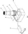
- the present invention as illustrated in Fig. 1 includes an induction heating unit (1) connected to an AC power supply and governed by an AC-DC regulator (2).
- FIG. 2 an exploded view of the present invention is illustrated which includes a main housing having a top surface (36) with power supply (2). Disposed inside housing, an induction heating coil (3) surrounds receptacle (4). A product cup (6) is removably inserted within receptacle (4). A conductive target floating screen (7) is removably inserted within product cup (6) adapted to float on the upper surface of the product within the cup.
- conductive target floating screen herein is meant that it is the only element within the product cup (6) that is heated by the induction heating coil (3). It is also emphasized that the heated target screen (7) heats and/or melts the upper surface region of the product within the product cup (6). The product is not heated directly by the induction heater coil (3). Also shown is operator interface or user interface window (5) which allows the user to interact with the device through visual and touch based actions.
- product cup (6) contains product that are to be heated by the conductive target screen (7).
- the screen made of a conductive semi porous material.
- the preferred embodiment is a porous conductive mesh.
- This screen sits on top of the product to be heated and localizes heat energy to the top layer of the product.
- an applicator such as a shaving brush or skin pad.
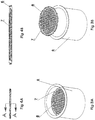
- a floatation device (8) surrounds the edge of the screen in order to prevent the screen from sinking into the material during liquefaction of the upper region of the product.
- the floatation device may be constructed out of buoyant materials or may contain an air pocket.
- the edges of the screen can be attached to the floatation device in any conventional manner such as by molding techniques, adhesives, mechanical attachments or fusion welding, etc.
- Fig. 4B is a cross- sectional view along the lines A-A shown in Fig. 4A .
- the floatation device (8) and target screen (7) have collinear upper and lower surfaces.
- the configuration shown in Fig. 4B is not intended to be so limiting since any modified configuration of that shown in Fig. 4B is intended to lie within the scope of the present invention.
- the floatation device and target screen may not have collinear upper and lower surfaces. As long as the floatation device maintains the target screen proximate to the upper surface region of the product, any configuration will be adequate.
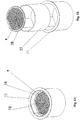
- a conductive target screen (9) and floatation device (10) is removably inserted within product cup (12) which is removably inserted within receptacle (11).
- These components are similar to those shown in Figs. 3A and 3B , but are modified with a non-circular geometry.
- each component has at least one flat surface for aligning the components in assembled position and preventing rotation while collecting the product onto the applicator.
- this embodiment is shown to have flat surfaces, any other configuration could be employed to align and prevent rotation of the components during use.
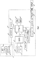
- FIG. 6 a block diagram of the control system of the present invention is illustrated.
- a standard wall outlet AC line input (13), a standard electromagnetic transformer (15), and AC to DC rectifier (16) is provided to power the electromechanical components enclosed within a housing indicated by dotted line (2) which provides power to the main housing (14), which is shown as component (1) in Figs. 1 and 2 .
- the system further includes a standard IC regulator chip (17) that lowers the voltage to power the sensitive digital components.
- An operator interface (18) is accessed by window (5) shown in Fig. 2 .
- a microprocessor unit (19) controls level of electromagnetic energy in the resonant tank (26), internal receptacle workcoil (27), and conductive screen (7).
- the microprocessor (19) accomplishes this by adjusting the oscillation frequency in the HF converter (25) by means of pulse width modulation (PWM).
- PWM pulse width modulation
- the microprocessor (19) also controls the operator interface (18), temperature sensor (20), current sensor (21), antenna (22) and electro-acoustic transducer (23).
- the temperature sensor (20) is capable of reading the internal board component temperatures of the microprocessor as well as the temperatures of the receptacle windings workcoil.
- the current sensor (21) is configured to measure the current draw through the switching circuit within the microprocessor.
- the antenna (22) which can be any conventional type, such as a dipole, helical, periodic, loop, etc., is configured to receive information from remote modules or transmit data to an external remote control device, for example, via Bluetooth technology.
- the electro-acoustic transducer (23) can be any conventional type, such as a speaker, capable of producing warnings such as over-heating temperatures or other helpful aids to the user throughout the heat cycle. It may also provide instructions during the product application.
- the transducer may also be configured in such a manner that it records electrical-mechanical pulses and is read by a signal processor (24).
- the signal processor (24) is a standard signal processing unit used to decode information received from the antenna (22) and transmit information via the electro-acoustic transducer (23).
- the HF converter (25) converts DC power to high frequency AC by means of receiving pulse width modulated signals from the microprocessor (19) and receiving high levels of DC power from rectifier (16).
- the high frequency AC generated by converter (25) is then passed into a series, parallel, quasi- series, or quasi-parallel resistor, capacitor, and inductor network called a Resonant Tank (26).
- Tank (26) has a resonant frequency determined by the resistor, inductor, and capacitor (RLC) configuration therein. As current passes through the resonant tank (26), it travels through a large wound conductive copper coil (27) which is shown as element (3) in Fig. 2 .
- the Resonant Tank (26) frequency is optimized through means of electrical reprogramming and tuning carried out by the microprocessor (19) and high frequency converter (25).
- This system allows the device to deliver precise amounts of current into the internal receptacle workcoil (indicated as (27) if Fig. 6 and ( 3 ) in Fig. 2 ) to heat the external cup workpiece (indicated as (28) in Fig. 6 and as "conductive target floating screen” (7) in Fig. 2 )., which also limits the system from overheating the various components of the system.
- the microprocessor (19) monitors the current sensor (21) and temperature sensors (20) to ensure safe operation of the device.
- the coil is not visible to the outside of housing (1) and surrounds receptacle (4) and nested product cup (6) with target screen (7) resting on the top surface product within cup (6).
- the target screen (7) is closely coupled to the coil (27) which creates an electromagnetic field that passes electromagnetic energy into the external cup workpiece (28) which is the conductive target screen (7) shown in Fig. 2 .
- the target screen only is heated by the electromagnetic energy which is then transferred to the upper surface of the product within the cup.
- RF module (31) which comprises the antenna (22) and signal processor (24) seen in Fig. 6 , microprocessing unit (19), DC regulator (17), HF converter (25), resonant tank (26), speaker (23), current sensor (21), and temperature sensor (20) are mounted on a main board (32). Power is fed in from a standard electrical wall outlet mains AC at (13). Power fed in is received by power supply (2) which includes transformer (15) and AC-DC rectifier (16) where it is converted into DC power and sent to the remaining components via the DC regulator (17), located on the main board (32).
- power supply (2) which includes transformer (15) and AC-DC rectifier (16) where it is converted into DC power and sent to the remaining components via the DC regulator (17), located on the main board (32).
- a circuit breaker (33) is utilized as a safety fault in the event of a large current consumption by the device.
- the operator interface (18) connects into the main board by means of a multi-conductor cable harness (35).
- an RF module (31) contains the antenna (22) and signal processor (24).
- the RF module (31) transmits and receives information through antenna (22).
- Data received and sent passes through a signal processing unit (24) during read and write cycles of the communication buffer.
- the main board is controlled by microprocessing unit (19). Low voltage DC power is converted from high voltage DC by means of a DC regulator IC chip (17) located on the main board (32).
- Operation of the electromechanical system of the present invention is a follows. First power is received by connecting (13), mains line AC power into the device with a plug. Voltage received is then electromagnetically reduced by transformer (15) and converted into direct current (DC) waveform by rectifier (16). Transformer (15) and rectifier (16) may be packaged together externally in an AC to DC power supply commonly used by computers or electronic devices. Inside the device the rectified DC power is passed through DC regulator (17), a monolithic integrated circuit regulator that step down the voltage to TTL, CMOS, ECL levels etc. The induction heater coil (3) is controlled by the microprocessor (19), which controls the timing and frequency of the HF converter (25), sensors (20), (21), operator interface (18), led lights (34), timers, antenna (22), and speaker (23).
- the microprocessor is programmed to control and vary the oscillation frequency in order to reach electromagnetic resonance between the workpiece, i.e., the screen, and the resonant tank.
- the microprocessor has flash memory read-while- write capabilities and EEPROM storage used in order to store user settings, timers, and safeties. Users are able to interact with the device by visually watching or pressing the operator interface (18) or user pushbuttons (29). Display of operator interface (18) is constructed of a piezoresistive, capacitive, surface acoustic, infrared grid or similar technologies. It allows the user to press and start a heating cycle while displaying helpful information based on the temperature or duration of the cycle.
- Safety information can be depicted on this display or any other helpful visual aids.
- a speaker (23) is used to provide audible feedback and alerts to the user based on the state of the heat cycle.
- the pushbuttons (29) are used as a secondary source of user input.
- Nearby LEDs (34) are used to provide a secondary visual indication of the state of the device. Pushbuttons, LEDs, and the Operator Interface may be reprogrammed by the manufacturer in order to adjust the functionality and usability throughout different device revisions.
- the microprocessor (19) inputs a low voltage pulse width modulated (PWM) signal received by the high frequency (HF) converter module (25).
- PWM pulse width modulated
- the converter module switches the rectified DC power from rectifier (16) to HF alternating current power at the oscillation frequency set by the microprocessor (19).
- High frequency AC power is then passed into a series or parallel resonant RLC tank.
- the tanks capacitance, inductance, and resistance are optimized to reach the resonant frequency of the PWM signal. This resonance also matches the oscillation frequency of the screen (7 or 9).
- current transferred into screen (7 or 9) is measured by sensor (21).
- microprocessor (19) adjusts the oscillation frequency in order to transfer maximum power into screen (7 or 9). If the current exceeds a safety limit measured by sensor (21), the device shuts off the heat cycle.
- the temperature of the internal components is measured by sensor (20).
- Sensor (20) also measures the internal coil (3) temperature to prevent overheating on its internal windings.
- high frequency currents are passed through the resonant tank (26) and into the coil (3) wrapped around a receptacle (4 or 11) that receives the cup (6 or 12).
- the high frequency currents are then transferred to screen (7 or 9) through means of electromagnetic induction. Eddy currents are generated inside screen (7 or 9) and cause a Joule heating effect as well as a heating through magnetic hysteresis. Heat generated through screen (7 or 9) then permeates through to the top layer of the product inside the cup. Due to the geometry of the screen (7 or 9), energy is transferred more directly to the top layer of the product inside cup (6 or 12),
Landscapes
- Physics & Mathematics (AREA)
- Electromagnetism (AREA)
- Engineering & Computer Science (AREA)
- Mechanical Engineering (AREA)
- General Induction Heating (AREA)
Applications Claiming Priority (2)
| Application Number | Priority Date | Filing Date | Title |
|---|---|---|---|
| US14/341,696 US9469521B2 (en) | 2014-07-25 | 2014-07-25 | Induction heating device for shaving and cosmetic applications |
| PCT/US2015/050991 WO2016015063A2 (en) | 2014-07-25 | 2015-09-18 | Induction heating device for shaving and cosmetic applications |
Publications (3)
| Publication Number | Publication Date |
|---|---|
| EP3247242A2 EP3247242A2 (en) | 2017-11-29 |
| EP3247242A4 EP3247242A4 (en) | 2018-02-21 |
| EP3247242B1 true EP3247242B1 (en) | 2019-03-13 |
Family
ID=55163989
Family Applications (1)
| Application Number | Title | Priority Date | Filing Date |
|---|---|---|---|
| EP15825272.6A Not-in-force EP3247242B1 (en) | 2014-07-25 | 2015-09-18 | Induction heating device for shaving and cosmetic applications |
Country Status (6)
| Country | Link |
|---|---|
| US (4) | US9469521B2 (OSRAM) |
| EP (1) | EP3247242B1 (OSRAM) |
| JP (1) | JP6563481B2 (OSRAM) |
| KR (1) | KR102347610B1 (OSRAM) |
| CN (1) | CN107072371B (OSRAM) |
| WO (1) | WO2016015063A2 (OSRAM) |
Families Citing this family (31)
| Publication number | Priority date | Publication date | Assignee | Title |
|---|---|---|---|---|
| GB2504733B (en) * | 2012-08-08 | 2015-05-20 | Reckitt & Colman Overseas | Device for evaporating a volatile material |
| GB2516924B (en) * | 2013-08-07 | 2016-01-20 | Reckitt Benckiser Brands Ltd | Device for evaporating a volatile fluid |
| CN106255430B (zh) * | 2014-04-30 | 2020-08-04 | 菲利普莫里斯生产公司 | 具有气溶胶生成装置加热器的容器以及气溶胶生成装置 |
| US20160037893A1 (en) * | 2014-07-31 | 2016-02-11 | Gary Walker | Deodorant saver |
| EP3209945A1 (en) * | 2014-10-20 | 2017-08-30 | Numerical Design, Inc. | Microfluidic-based apparatus and method for vaporization of liquids |
| EP3446543B1 (en) * | 2016-04-18 | 2023-05-10 | Alps South Europe s.r.o | Induction heater and dispenser |
| US10238200B2 (en) * | 2016-09-14 | 2019-03-26 | April Bartlett | Depilatory wax melting apparatus |
| KR102654915B1 (ko) * | 2016-12-13 | 2024-04-04 | 현대자동차주식회사 | 차량용 컵홀더 및 컵홀더용 텀블러 |
| EP3613258B1 (en) | 2017-04-17 | 2024-03-20 | Philip Morris Products S.A. | Devices, systems, and methods for sensing temperature in induction heating systems |
| KR20230096139A (ko) * | 2017-09-06 | 2023-06-29 | 제이티 인터내셔널 소시에떼 아노님 | 증기 생성 디바이스에 대한 유도 가열 어셈블리 |
| JP6946924B2 (ja) * | 2017-10-19 | 2021-10-13 | 株式会社デンソー | 共振インバータ装置 |
| IT201800004619A1 (it) * | 2018-04-17 | 2019-10-17 | Contenitore di un prodotto cosmetico o medicale | |
| ES2939341T3 (es) | 2018-05-17 | 2023-04-21 | Philip Morris Products Sa | Dispositivo generador de aerosol que tiene bobina inductora mejorada |
| EP3815463B1 (en) * | 2018-06-29 | 2025-12-24 | Breville Pty Limited | An induction jug heater |
| KR101986191B1 (ko) | 2018-07-11 | 2019-06-05 | 주식회사 선광코퍼레이션 | 이끼 식재가 가능한 태양광 설치 구조 |
| GB201814197D0 (en) * | 2018-08-31 | 2018-10-17 | Nicoventures Trading Ltd | Aerosol generating material characteristic determination |
| EP3855956B1 (en) | 2018-09-25 | 2022-09-07 | Philip Morris Products S.A. | Inductive heating assembly for inductive heating of an aerosol-forming substrate |
| CN112739228B (zh) * | 2018-09-25 | 2024-04-26 | 菲利普莫里斯生产公司 | 用于感应加热气溶胶形成基材的加热组件和方法 |
| CN112739226B (zh) | 2018-09-25 | 2024-08-13 | 菲利普莫里斯生产公司 | 包括感受器组件的感应加热式气溶胶生成装置 |
| BR112021005386A2 (pt) | 2018-09-25 | 2021-06-22 | Philip Morris Products S.A. | artigo gerador de aerossol aquecível indutivamente compreendendo um substrato formador de aerossol e um conjunto susceptor |
| WO2020064685A1 (en) | 2018-09-25 | 2020-04-02 | Philip Morris Products S.A. | Susceptor assembly for inductively heating an aerosol-forming substrate |
| IT201900002861A1 (it) * | 2019-02-27 | 2020-08-27 | Giannantonio Spotorno | Apparato per la cottura automatica e veloce di cibi |
| WO2020223350A1 (en) | 2019-04-29 | 2020-11-05 | Loto Labs, Inc. | System, method, and computer program product for determining a characteristic of a susceptor |
| AU2020277040B2 (en) * | 2019-05-10 | 2025-09-11 | Fuji Oil Co., Ltd. | Melting device, melting method, and double pipe |
| JP2020194643A (ja) * | 2019-05-24 | 2020-12-03 | 株式会社ブラウニー | 電磁誘導加熱機 |
| US20200390986A1 (en) * | 2019-06-11 | 2020-12-17 | Dr. Dabber, Inc. | Induction powered vaporizer device capable of utilizing solid or liquid products |
| CN110772150A (zh) * | 2019-11-12 | 2020-02-11 | 泰山学院 | 刷牙杯及加热装置 |
| USD933889S1 (en) * | 2020-07-16 | 2021-10-19 | Shenzhen Huishangke Technology Co., Ltd. | Wax melting pot |
| USD933294S1 (en) * | 2020-08-17 | 2021-10-12 | Guangzhou Weiyuan Electronics Co., Ltd. | Wax heater |
| USD932102S1 (en) * | 2020-08-31 | 2021-09-28 | Wu Deng | Wax machine |
| US20240349865A1 (en) * | 2023-04-18 | 2024-10-24 | Paul Raymond | Dispensing head for shaving foam |
Family Cites Families (24)
| Publication number | Priority date | Publication date | Assignee | Title |
|---|---|---|---|---|
| US2867347A (en) | 1956-02-04 | 1959-01-06 | British Petroleum Co | Liquid storage apparatus |
| DE19729661A1 (de) * | 1997-07-11 | 1999-01-14 | Ego Elektro Geraetebau Gmbh | Erwärmungssystem |
| US6499595B1 (en) * | 1999-07-29 | 2002-12-31 | The Gillette Company | Container for shaving cartridge or other stored item |
| JP2003075073A (ja) * | 2001-08-31 | 2003-03-12 | Mitsubishi Heavy Ind Ltd | 放射性廃棄物溶融炉およびその運転方法 |
| NL1023670C1 (nl) | 2002-07-03 | 2004-01-06 | Keltub B V | Samenstel van balg en afroldeel, pomp en werkwijze voor het gebruik daarvan. |
| JP2006507196A (ja) * | 2002-11-21 | 2006-03-02 | エス.シー. ジョンソン アンド サン、インコーポレイテッド | 製品消費者に情報を提供するためのrfidタグを有する製品 |
| FR2852795B1 (fr) * | 2003-03-24 | 2005-05-06 | Oreal | Ensemble de conditionnement et d'application d'un produit cosmetique et ou de soins comportant un moyen chauffant |
| DE602004008284T2 (de) * | 2003-06-27 | 2007-11-22 | S.C. Johnson & Son, Inc., Racine | Spenderbaugruppen und -systeme mit einer wärmespeichereinheit |
| GB0410777D0 (en) | 2004-05-14 | 2004-06-16 | Givauden Sa | Apparatus |
| DE102004031942A1 (de) * | 2004-06-30 | 2006-01-19 | Wella Ag | Verfahren zum Aufwärmen einer Flüssigkeit vor ihrem Gebrauch sowie eine Vorrichtung zur Durchführung des Verfahrens |
| WO2007120791A2 (en) * | 2006-04-13 | 2007-10-25 | S. C. Johnson & Son, Inc. | Heated flowable product dispenser |
| US7804045B2 (en) | 2006-08-28 | 2010-09-28 | Ameritherm, Inc. | Portable food heater |
| JP4722020B2 (ja) * | 2006-11-28 | 2011-07-13 | 三菱電機株式会社 | 電磁誘導加熱調理器 |
| JP5070870B2 (ja) | 2007-02-09 | 2012-11-14 | 東洋製罐株式会社 | 誘導加熱発熱体、及び誘導加熱容器 |
| US8014436B2 (en) | 2008-07-02 | 2011-09-06 | Telefonaktiebolaget L M Ericsson (Publ) | Multi-dimensional signal of reduced peak-to-RMS ratio |
| US20100000980A1 (en) * | 2008-07-02 | 2010-01-07 | Bogdan Popescu | Induction Heating System with Versatile Inductive Cartridge |
| US8882378B2 (en) | 2010-02-15 | 2014-11-11 | Access Business Group International Llc | Heating and dispenser system |
| US9585202B2 (en) | 2011-05-20 | 2017-02-28 | Cooktek Induction Systems, Llc | Induction-based food holding/warming system and method |
| GB201109909D0 (en) * | 2011-06-14 | 2011-07-27 | Mcgarvey Connie | Induction heating device for heating a liquid |
| GB2504730B (en) | 2012-08-08 | 2015-01-14 | Reckitt & Colman Overseas | Device for evaporating a volatile fluid |
| GB2504733B (en) * | 2012-08-08 | 2015-05-20 | Reckitt & Colman Overseas | Device for evaporating a volatile material |
| GB2504732B (en) * | 2012-08-08 | 2015-01-14 | Reckitt & Colman Overseas | Device for evaporating a volatile material |
| GB2504731B (en) * | 2012-08-08 | 2015-03-25 | Reckitt & Colman Overseas | Device for evaporating a volatile fluid |
| GB2516925B (en) * | 2013-08-07 | 2016-01-27 | Reckitt Benckiser Brands Ltd | Device for evaporating a volatile material |
-
2014
- 2014-07-25 US US14/341,696 patent/US9469521B2/en not_active Expired - Fee Related
-
2015
- 2015-09-18 KR KR1020177005374A patent/KR102347610B1/ko not_active Expired - Fee Related
- 2015-09-18 EP EP15825272.6A patent/EP3247242B1/en not_active Not-in-force
- 2015-09-18 JP JP2017505252A patent/JP6563481B2/ja not_active Expired - Fee Related
- 2015-09-18 CN CN201580051931.7A patent/CN107072371B/zh not_active Expired - Fee Related
- 2015-09-18 WO PCT/US2015/050991 patent/WO2016015063A2/en not_active Ceased
-
2016
- 2016-04-18 US US15/131,126 patent/US9743463B2/en not_active Expired - Fee Related
-
2017
- 2017-04-18 US US15/490,363 patent/US11026299B2/en active Active
-
2021
- 2021-04-30 US US17/245,593 patent/US11641700B2/en active Active
Non-Patent Citations (1)
| Title |
|---|
| None * |
Also Published As
| Publication number | Publication date |
|---|---|
| CN107072371B (zh) | 2020-09-11 |
| US11641700B2 (en) | 2023-05-02 |
| US9469521B2 (en) | 2016-10-18 |
| US20160023887A1 (en) | 2016-01-28 |
| US20170303344A1 (en) | 2017-10-19 |
| EP3247242A4 (en) | 2018-02-21 |
| WO2016015063A2 (en) | 2016-01-28 |
| US9743463B2 (en) | 2017-08-22 |
| US20210249795A1 (en) | 2021-08-12 |
| WO2016015063A3 (en) | 2016-03-24 |
| KR20170094542A (ko) | 2017-08-18 |
| US20160234886A1 (en) | 2016-08-11 |
| KR102347610B1 (ko) | 2022-01-07 |
| US11026299B2 (en) | 2021-06-01 |
| CN107072371A (zh) | 2017-08-18 |
| JP6563481B2 (ja) | 2019-08-21 |
| EP3247242A2 (en) | 2017-11-29 |
| JP2017529650A (ja) | 2017-10-05 |
Similar Documents
| Publication | Publication Date | Title |
|---|---|---|
| EP3247242B1 (en) | Induction heating device for shaving and cosmetic applications | |
| US7829827B2 (en) | Radio frequency (RF) induction cooking food heater | |
| US9642191B2 (en) | Portable container system for heating a beverage | |
| US7804045B2 (en) | Portable food heater | |
| US8882378B2 (en) | Heating and dispenser system | |
| KR101821837B1 (ko) | Pos 유도성 시스템 및 방법 | |
| JP2020512171A (ja) | スマート包装、システム、及び方法 | |
| JP2017529650A5 (OSRAM) | ||
| EP3446543B1 (en) | Induction heater and dispenser | |
| WO2003062720A2 (en) | Apparatus for varying the temperature of a container for food or drinks | |
| JP2019516228A5 (OSRAM) | ||
| CN111184437A (zh) | 手势控制的液体加热器具及用于其的手势控制的方法 | |
| CN107280385A (zh) | 一种带有提醒功能的水杯 | |
| CN118368761A (zh) | 电磁加热系统 | |
| KR20200073848A (ko) | 전력 공급 구조가 개선된 전기 포트 |
Legal Events
| Date | Code | Title | Description |
|---|---|---|---|
| STAA | Information on the status of an ep patent application or granted ep patent |
Free format text: STATUS: THE INTERNATIONAL PUBLICATION HAS BEEN MADE |
|
| PUAI | Public reference made under article 153(3) epc to a published international application that has entered the european phase |
Free format text: ORIGINAL CODE: 0009012 |
|
| STAA | Information on the status of an ep patent application or granted ep patent |
Free format text: STATUS: REQUEST FOR EXAMINATION WAS MADE |
|
| 17P | Request for examination filed |
Effective date: 20170216 |
|
| AK | Designated contracting states |
Kind code of ref document: A2 Designated state(s): AL AT BE BG CH CY CZ DE DK EE ES FI FR GB GR HR HU IE IS IT LI LT LU LV MC MK MT NL NO PL PT RO RS SE SI SK SM TR |
|
| AX | Request for extension of the european patent |
Extension state: BA ME |
|
| A4 | Supplementary search report drawn up and despatched |
Effective date: 20180124 |
|
| RIC1 | Information provided on ipc code assigned before grant |
Ipc: H05B 6/10 20060101ALI20180118BHEP Ipc: A45D 27/22 20060101AFI20180118BHEP |
|
| GRAP | Despatch of communication of intention to grant a patent |
Free format text: ORIGINAL CODE: EPIDOSNIGR1 |
|
| STAA | Information on the status of an ep patent application or granted ep patent |
Free format text: STATUS: GRANT OF PATENT IS INTENDED |
|
| DAX | Request for extension of the european patent (deleted) | ||
| INTG | Intention to grant announced |
Effective date: 20180928 |
|
| DAV | Request for validation of the european patent (deleted) | ||
| GRAS | Grant fee paid |
Free format text: ORIGINAL CODE: EPIDOSNIGR3 |
|
| GRAA | (expected) grant |
Free format text: ORIGINAL CODE: 0009210 |
|
| STAA | Information on the status of an ep patent application or granted ep patent |
Free format text: STATUS: THE PATENT HAS BEEN GRANTED |
|
| AK | Designated contracting states |
Kind code of ref document: B1 Designated state(s): AL AT BE BG CH CY CZ DE DK EE ES FI FR GB GR HR HU IE IS IT LI LT LU LV MC MK MT NL NO PL PT RO RS SE SI SK SM TR |
|
| REG | Reference to a national code |
Ref country code: GB Ref legal event code: FG4D |
|
| REG | Reference to a national code |
Ref country code: CH Ref legal event code: EP Ref country code: AT Ref legal event code: REF Ref document number: 1106495 Country of ref document: AT Kind code of ref document: T Effective date: 20190315 |
|
| REG | Reference to a national code |
Ref country code: DE Ref legal event code: R096 Ref document number: 602015026529 Country of ref document: DE |
|
| REG | Reference to a national code |
Ref country code: IE Ref legal event code: FG4D |
|
| REG | Reference to a national code |
Ref country code: NL Ref legal event code: MP Effective date: 20190313 |
|
| REG | Reference to a national code |
Ref country code: LT Ref legal event code: MG4D |
|
| PG25 | Lapsed in a contracting state [announced via postgrant information from national office to epo] |
Ref country code: LT Free format text: LAPSE BECAUSE OF FAILURE TO SUBMIT A TRANSLATION OF THE DESCRIPTION OR TO PAY THE FEE WITHIN THE PRESCRIBED TIME-LIMIT Effective date: 20190313 Ref country code: FI Free format text: LAPSE BECAUSE OF FAILURE TO SUBMIT A TRANSLATION OF THE DESCRIPTION OR TO PAY THE FEE WITHIN THE PRESCRIBED TIME-LIMIT Effective date: 20190313 Ref country code: NO Free format text: LAPSE BECAUSE OF FAILURE TO SUBMIT A TRANSLATION OF THE DESCRIPTION OR TO PAY THE FEE WITHIN THE PRESCRIBED TIME-LIMIT Effective date: 20190613 Ref country code: SE Free format text: LAPSE BECAUSE OF FAILURE TO SUBMIT A TRANSLATION OF THE DESCRIPTION OR TO PAY THE FEE WITHIN THE PRESCRIBED TIME-LIMIT Effective date: 20190313 |
|
| PG25 | Lapsed in a contracting state [announced via postgrant information from national office to epo] |
Ref country code: BG Free format text: LAPSE BECAUSE OF FAILURE TO SUBMIT A TRANSLATION OF THE DESCRIPTION OR TO PAY THE FEE WITHIN THE PRESCRIBED TIME-LIMIT Effective date: 20190613 Ref country code: GR Free format text: LAPSE BECAUSE OF FAILURE TO SUBMIT A TRANSLATION OF THE DESCRIPTION OR TO PAY THE FEE WITHIN THE PRESCRIBED TIME-LIMIT Effective date: 20190614 Ref country code: RS Free format text: LAPSE BECAUSE OF FAILURE TO SUBMIT A TRANSLATION OF THE DESCRIPTION OR TO PAY THE FEE WITHIN THE PRESCRIBED TIME-LIMIT Effective date: 20190313 Ref country code: LV Free format text: LAPSE BECAUSE OF FAILURE TO SUBMIT A TRANSLATION OF THE DESCRIPTION OR TO PAY THE FEE WITHIN THE PRESCRIBED TIME-LIMIT Effective date: 20190313 Ref country code: HR Free format text: LAPSE BECAUSE OF FAILURE TO SUBMIT A TRANSLATION OF THE DESCRIPTION OR TO PAY THE FEE WITHIN THE PRESCRIBED TIME-LIMIT Effective date: 20190313 Ref country code: NL Free format text: LAPSE BECAUSE OF FAILURE TO SUBMIT A TRANSLATION OF THE DESCRIPTION OR TO PAY THE FEE WITHIN THE PRESCRIBED TIME-LIMIT Effective date: 20190313 |
|
| REG | Reference to a national code |
Ref country code: AT Ref legal event code: MK05 Ref document number: 1106495 Country of ref document: AT Kind code of ref document: T Effective date: 20190313 |
|
| PG25 | Lapsed in a contracting state [announced via postgrant information from national office to epo] |
Ref country code: CZ Free format text: LAPSE BECAUSE OF FAILURE TO SUBMIT A TRANSLATION OF THE DESCRIPTION OR TO PAY THE FEE WITHIN THE PRESCRIBED TIME-LIMIT Effective date: 20190313 Ref country code: IT Free format text: LAPSE BECAUSE OF FAILURE TO SUBMIT A TRANSLATION OF THE DESCRIPTION OR TO PAY THE FEE WITHIN THE PRESCRIBED TIME-LIMIT Effective date: 20190313 Ref country code: RO Free format text: LAPSE BECAUSE OF FAILURE TO SUBMIT A TRANSLATION OF THE DESCRIPTION OR TO PAY THE FEE WITHIN THE PRESCRIBED TIME-LIMIT Effective date: 20190313 Ref country code: SK Free format text: LAPSE BECAUSE OF FAILURE TO SUBMIT A TRANSLATION OF THE DESCRIPTION OR TO PAY THE FEE WITHIN THE PRESCRIBED TIME-LIMIT Effective date: 20190313 Ref country code: AL Free format text: LAPSE BECAUSE OF FAILURE TO SUBMIT A TRANSLATION OF THE DESCRIPTION OR TO PAY THE FEE WITHIN THE PRESCRIBED TIME-LIMIT Effective date: 20190313 Ref country code: PT Free format text: LAPSE BECAUSE OF FAILURE TO SUBMIT A TRANSLATION OF THE DESCRIPTION OR TO PAY THE FEE WITHIN THE PRESCRIBED TIME-LIMIT Effective date: 20190713 Ref country code: ES Free format text: LAPSE BECAUSE OF FAILURE TO SUBMIT A TRANSLATION OF THE DESCRIPTION OR TO PAY THE FEE WITHIN THE PRESCRIBED TIME-LIMIT Effective date: 20190313 Ref country code: EE Free format text: LAPSE BECAUSE OF FAILURE TO SUBMIT A TRANSLATION OF THE DESCRIPTION OR TO PAY THE FEE WITHIN THE PRESCRIBED TIME-LIMIT Effective date: 20190313 |
|
| PG25 | Lapsed in a contracting state [announced via postgrant information from national office to epo] |
Ref country code: SM Free format text: LAPSE BECAUSE OF FAILURE TO SUBMIT A TRANSLATION OF THE DESCRIPTION OR TO PAY THE FEE WITHIN THE PRESCRIBED TIME-LIMIT Effective date: 20190313 Ref country code: PL Free format text: LAPSE BECAUSE OF FAILURE TO SUBMIT A TRANSLATION OF THE DESCRIPTION OR TO PAY THE FEE WITHIN THE PRESCRIBED TIME-LIMIT Effective date: 20190313 |
|
| REG | Reference to a national code |
Ref country code: DE Ref legal event code: R097 Ref document number: 602015026529 Country of ref document: DE |
|
| PG25 | Lapsed in a contracting state [announced via postgrant information from national office to epo] |
Ref country code: IS Free format text: LAPSE BECAUSE OF FAILURE TO SUBMIT A TRANSLATION OF THE DESCRIPTION OR TO PAY THE FEE WITHIN THE PRESCRIBED TIME-LIMIT Effective date: 20190713 Ref country code: AT Free format text: LAPSE BECAUSE OF FAILURE TO SUBMIT A TRANSLATION OF THE DESCRIPTION OR TO PAY THE FEE WITHIN THE PRESCRIBED TIME-LIMIT Effective date: 20190313 |
|
| PLBE | No opposition filed within time limit |
Free format text: ORIGINAL CODE: 0009261 |
|
| STAA | Information on the status of an ep patent application or granted ep patent |
Free format text: STATUS: NO OPPOSITION FILED WITHIN TIME LIMIT |
|
| PG25 | Lapsed in a contracting state [announced via postgrant information from national office to epo] |
Ref country code: DK Free format text: LAPSE BECAUSE OF FAILURE TO SUBMIT A TRANSLATION OF THE DESCRIPTION OR TO PAY THE FEE WITHIN THE PRESCRIBED TIME-LIMIT Effective date: 20190313 |
|
| 26N | No opposition filed |
Effective date: 20191216 |
|
| PG25 | Lapsed in a contracting state [announced via postgrant information from national office to epo] |
Ref country code: SI Free format text: LAPSE BECAUSE OF FAILURE TO SUBMIT A TRANSLATION OF THE DESCRIPTION OR TO PAY THE FEE WITHIN THE PRESCRIBED TIME-LIMIT Effective date: 20190313 |
|
| PGFP | Annual fee paid to national office [announced via postgrant information from national office to epo] |
Ref country code: BE Payment date: 20190927 Year of fee payment: 5 |
|
| PG25 | Lapsed in a contracting state [announced via postgrant information from national office to epo] |
Ref country code: TR Free format text: LAPSE BECAUSE OF FAILURE TO SUBMIT A TRANSLATION OF THE DESCRIPTION OR TO PAY THE FEE WITHIN THE PRESCRIBED TIME-LIMIT Effective date: 20190313 |
|
| PGFP | Annual fee paid to national office [announced via postgrant information from national office to epo] |
Ref country code: CH Payment date: 20191002 Year of fee payment: 5 |
|
| PG25 | Lapsed in a contracting state [announced via postgrant information from national office to epo] |
Ref country code: MC Free format text: LAPSE BECAUSE OF FAILURE TO SUBMIT A TRANSLATION OF THE DESCRIPTION OR TO PAY THE FEE WITHIN THE PRESCRIBED TIME-LIMIT Effective date: 20190313 |
|
| PG25 | Lapsed in a contracting state [announced via postgrant information from national office to epo] |
Ref country code: LU Free format text: LAPSE BECAUSE OF NON-PAYMENT OF DUE FEES Effective date: 20190918 Ref country code: IE Free format text: LAPSE BECAUSE OF NON-PAYMENT OF DUE FEES Effective date: 20190918 |
|
| REG | Reference to a national code |
Ref country code: CH Ref legal event code: PL |
|
| PG25 | Lapsed in a contracting state [announced via postgrant information from national office to epo] |
Ref country code: CY Free format text: LAPSE BECAUSE OF FAILURE TO SUBMIT A TRANSLATION OF THE DESCRIPTION OR TO PAY THE FEE WITHIN THE PRESCRIBED TIME-LIMIT Effective date: 20190313 |
|
| REG | Reference to a national code |
Ref country code: BE Ref legal event code: MM Effective date: 20200930 |
|
| PG25 | Lapsed in a contracting state [announced via postgrant information from national office to epo] |
Ref country code: MT Free format text: LAPSE BECAUSE OF FAILURE TO SUBMIT A TRANSLATION OF THE DESCRIPTION OR TO PAY THE FEE WITHIN THE PRESCRIBED TIME-LIMIT Effective date: 20190313 Ref country code: HU Free format text: LAPSE BECAUSE OF FAILURE TO SUBMIT A TRANSLATION OF THE DESCRIPTION OR TO PAY THE FEE WITHIN THE PRESCRIBED TIME-LIMIT; INVALID AB INITIO Effective date: 20150918 |
|
| PG25 | Lapsed in a contracting state [announced via postgrant information from national office to epo] |
Ref country code: LI Free format text: LAPSE BECAUSE OF NON-PAYMENT OF DUE FEES Effective date: 20200930 Ref country code: CH Free format text: LAPSE BECAUSE OF NON-PAYMENT OF DUE FEES Effective date: 20200930 Ref country code: BE Free format text: LAPSE BECAUSE OF NON-PAYMENT OF DUE FEES Effective date: 20200930 |
|
| PG25 | Lapsed in a contracting state [announced via postgrant information from national office to epo] |
Ref country code: MK Free format text: LAPSE BECAUSE OF FAILURE TO SUBMIT A TRANSLATION OF THE DESCRIPTION OR TO PAY THE FEE WITHIN THE PRESCRIBED TIME-LIMIT Effective date: 20190313 |
|
| PGFP | Annual fee paid to national office [announced via postgrant information from national office to epo] |
Ref country code: GB Payment date: 20220927 Year of fee payment: 8 Ref country code: DE Payment date: 20220928 Year of fee payment: 8 |
|
| PGFP | Annual fee paid to national office [announced via postgrant information from national office to epo] |
Ref country code: FR Payment date: 20220926 Year of fee payment: 8 |
|
| REG | Reference to a national code |
Ref country code: DE Ref legal event code: R119 Ref document number: 602015026529 Country of ref document: DE |
|
| GBPC | Gb: european patent ceased through non-payment of renewal fee |
Effective date: 20230918 |
|
| PG25 | Lapsed in a contracting state [announced via postgrant information from national office to epo] |
Ref country code: GB Free format text: LAPSE BECAUSE OF NON-PAYMENT OF DUE FEES Effective date: 20230918 |
|
| PG25 | Lapsed in a contracting state [announced via postgrant information from national office to epo] |
Ref country code: GB Free format text: LAPSE BECAUSE OF NON-PAYMENT OF DUE FEES Effective date: 20230918 Ref country code: FR Free format text: LAPSE BECAUSE OF NON-PAYMENT OF DUE FEES Effective date: 20230930 Ref country code: DE Free format text: LAPSE BECAUSE OF NON-PAYMENT OF DUE FEES Effective date: 20240403 |