EP3246509B1 - Leiter - Google Patents
Leiter Download PDFInfo
- Publication number
- EP3246509B1 EP3246509B1 EP17171244.1A EP17171244A EP3246509B1 EP 3246509 B1 EP3246509 B1 EP 3246509B1 EP 17171244 A EP17171244 A EP 17171244A EP 3246509 B1 EP3246509 B1 EP 3246509B1
- Authority
- EP
- European Patent Office
- Prior art keywords
- plastic profile
- tread surface
- ladder according
- rung
- ladder
- Prior art date
- Legal status (The legal status is an assumption and is not a legal conclusion. Google has not performed a legal analysis and makes no representation as to the accuracy of the status listed.)
- Active
Links
Images


Classifications
-
- E—FIXED CONSTRUCTIONS
- E06—DOORS, WINDOWS, SHUTTERS, OR ROLLER BLINDS IN GENERAL; LADDERS
- E06C—LADDERS
- E06C7/00—Component parts, supporting parts, or accessories
- E06C7/08—Special construction of longitudinal members, or rungs or other treads
- E06C7/081—Rungs or other treads comprising anti-slip features
Definitions
- steps of ladders should be designed so that the user of the ladder can safely stand on the ladder even in unfavorable circumstances.
- a ladder step which is secured with a non-slip tread pad
- a V-shaped clip member 20 can be clipped onto a triangular ladder stage 2.
- a cushioning element is mounted on the clip member. It is covered with a cover member 50 having anti-slip properties.
- the DE 200 10 298 U1 shows a ladder with the tread of the rungs divided.
- a first part of the tread surface has upwardly pointing triton ribs and a second part has an arched plastic insert also with triplets.
- all solutions proposed so far have certain disadvantages.
- the present invention seeks to provide a ladder that is more durable, inexpensive to manufacture, but still provides the desired slip resistance according to standards even in very different unfavorable environments.
- a plastic profile with anti-slip equipment in the stage according to the invention is combined with a ladder having a special step surface of the step which has embossments with apertures.
- Embossments with openings have the particular advantage that due to the embossing technique, the surface adjacent to the openings is sharp-edged.
- the openings are formed as, for example, circular or hexagonal passage recesses.
- the plastic profile has a flat, vault-free surface which is pierced by sharp-pointed grains.
- the grains interact intensively with the sole of the shoe of a user, so that the profile projections of the sole first hang up on the grain tips and the sharp-edged grains then penetrate into the sole.
- a slip resistance is also given in the lateral direction, because the sharp-edged teeth of the grains are randomly distributed, so that a part of the teeth extends transversely to the step longitudinal direction and a part in the longitudinal direction.
- At least some of the sharp-pointed grains preferably have sharp edge angles, ie angles of less than 90 degrees, in such a way that the respective pointed edges point upwards.
- the "pointing upwards” should be understood to mean that the sharp edges extend out of the surrounding surface of the support layer, for example the synthetic resin layer, thus being exposed.
- the sharp edges extend with their axes at an angle of less than 45 degrees to the vertical.
- the slip resistance in this solution is independent of the axis, which represents a significant advance against corrugations, which are non-slip, for example, just under load the environment with oil in one axis, but extremely slippery in the other horizontal axis.
- the anti-slip equipment is designed as an arrangement of sharp-pointed grains, which are embedded in the plastic material.
- the height of the sharp-pointed grains corresponds to the height of the openings at their upper edge.
- mud or earth deposits partially press through the apertures in the step surface, so that the contact of the anti-slip ring at the top of the opening, which is sharp-edged, is ensured with the sole of the user. This is especially true when the user's sole is profiled, because then they typically express themselves Imprints in grooves or recesses of the sole, and thus improve the state still.
- the sharp-toothed grains sticking out of the surface of the plastic profile pass and tear a contaminant film that may be applied to the step by the user's shoes. Even if this is oil or soap soak, for example, a secure contact with the shoes of the user is made, in which the sharp prongs dig at least partially in a plastic sole of the user's shoes and thus lead to a secure anchorage.
- the grains according to the invention can protrude up to one millimeter from the plastic surface. However, they are embedded in them to ensure a secure anchorage, for example over half of their height.
- the surface texture of the grains is preferably irregular and randomly distributed, and the ridges and serrations of the grains result in improved slip resistance.
- the plastic profile extends over a corresponding recess in the surface of the step, above a step tube, which supports the step laterally on the spars.
- the plastic profile is preferably slightly wider than the recess and rests on the tread surface.
- the support height there corresponds substantially to the height of the embossments, so that the surface of the profile and the top of the embossments is at the same altitude.
- locking tongues are provided, whose outward, ie forward or backward, based on the step, pointing projections under the tread surface of the step.
- the locking tongues can spring inwards and thus allow a snapping of the plastic profile in the recess.
- the plastic profile is arranged with a certain play above the tube.
- this bends slightly in accordance with the curvature of the sole of the user until it is supported on the pipe. This ensures that a large-scale investment between sole and plastic profile is made possible without the plastic profile could bend too much or even lost.
- the openings extend in the rear region of the step.
- the front shoe area is the most muddy so that this area, through the perforations and protruding push-through function described above, is best suited for providing stability.
- the depth of the step is chosen so that it is significantly shorter than a shoe length, for example 12 cm. From the middle of the stage to the beginning of the second seventh of the step depth, the plastic profile according to the invention with the sharp-pointed grains extends at the top.
- the plastic profile is preferably provided via a kind of flocking with the sharp-toothed grains, which are then pressed by rewarming the plastic profile, which is characterized viscous, in this and hold there.
- the surface of the plastic profile may be provided with a not yet cured adhesive layer which then wets the spiky grains below and is partially pressed into the grain receptacle by them without the tips of the grains coming in contact with the adhesive layer.
- plastic profile - including the optional adhesive layer - is sufficiently temperature resistant in the work area of the ladder.
- the preferred working range here is considered to be -20 degrees Celsius to +50 degrees Celsius, it being understood that adjustments can be made both up and down by appropriate choice of suitable plastics and adhesives.
- the tube which may be formed as a rounded square tube, for example, extends laterally beyond the step, so that it ever passes through the spars of the ladder and is crimped there in a conventional manner.
- the step is provided with a rounded shin apron.
- the plastic profile is extended in the manner of a cover beyond the tibia apron out and behind this.
- the embossings according to the invention extend substantially conical and ends preferably in openings that are sharp-edged. Alternatively you can the embossing also be abraded without further ado, which also results in sharp edges, which are particularly suitable for providing stability.
- the step corresponds at least to the adhesive safety class R 12 and particularly preferably to the adhesive safety class R 13. This does not only apply to dry environments, so that the achievable class is insofar R 13B or even R 13C.
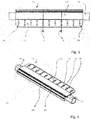
- the conductor according to the invention has two spars, not shown, between which extends a step or rung. In the case of the embodiment shown here, it is a step 10, which in cross section Fig. 1 is apparent.
- the step 10 has a tread surface 12 which is profiled, in a particular way.
- the step 10 is substantially made of metal, for example light metal such as aluminum.
- the tread surface 12 is divided, and a first part, the rear part when climbing the ladder, so facing away from the user, part is provided with embossments, wherein Fig. 1 three embossments 14, 16 and 18 can be seen.
- the embossments are designed to create raised areas around the embossments.
- the continuous metal of level 10, for example, as an extruded profile can be formed, is processed from below with corresponding embossing tools, so that the embossments are formed raised on the tread surface 12.
- the embossments 14 to 18 on openings 20, 22 and 24, which extend centrally in the embossments 14 to 18.
- the openings 20 and 24 are surrounded by sloping conical flanks of the embossments.
- Surrounding the aperture 20 and the aperture 24 is provided an annular surface 26 which is planar and preferably ends sharp-edged at the aperture 20 and also sharp-edged on the surrounding flank of the embossment 14.
- the apertures 20 and 22 are preferably generated by a punching movement from bottom to top, so that inside the annular surface 26 by the punching process, a burr is formed. This is, in order to avoid injury to the user, at least partially removed, but it is also possible, a burr stub, which then obliquely upwards inwardly - with respect to the opening 20 - projects to leave there to improve the stability still.
- the extruded profile of the stage 10 is first prepared by extrusion and then cut to length in the desired length, which corresponds to the step width. Following this, the embossments 14 to 18 and the openings 20 to 24 are generated.
- the extruder is then followed by a stamping / punching tool which has a stamping punch drum between which and a counterpressure drum passes the step.
- a stamping / punching tool which has a stamping punch drum between which and a counterpressure drum passes the step.
- the embossments are formed so that they surround apertures.
- imprints which are free of openings and leak, for example, in tips, which also have good adhesive properties.
- the openings allow the provision of a sharp annular edge 28, at the maximum height of the tread surface 12th is arranged and leads, for example, when using plastic shoes by the user to improve the stability.
- the stability in the longitudinal direction of the step and the stability in the transverse direction of the step are equal.
- This goal can be accommodated by the realization of circular annular edges 28 at the projecting openings, or it being understood that any other round or angular configuration of the opening is also possible, even without the desired effect that the stability given regardless of direction is, has been nullified.
- a second part is provided. This extends in front of the first part and thus closer to the user of the step when climbing the step.
- the second part has a tube 40, which carries a supporting function and is anchored end in the bars of the ladder.
- the tube is designed as a slightly oblique and rounded square tube and is produced in a conventional manner during the extrusion process of the stage.
- An inclined support flank 42 supports the first part of the tread surface 12 and extends approximately at an angle of 45 degrees from the pipe 40 starting obliquely upwards / backwards.
- a second support flank 44 extends at almost right angles to the first support flank 42 obliquely forward / upward.
- the second supporting flank 44 terminates in a front part 46 of the tread surface 12.
- a skirt 48 which extends obliquely forward / down and is crowned.
- the apron 48 is rounded at the same time shin-friendly and ends in a bulge 50th
- a plastic profile 52 is arranged according to the invention. It covers a recess 54, which is also formed above the tube 40.
- the recess 54 is bounded by a front support flange 56 and a rear support flange 58.
- the front support flange 56 is attached to the front portion 46 of the tread surface 12 and extends substantially horizontally rearwardly.
- the rear support flange 58 is attached to the first part of the tread surface 12 and extends substantially horizontally forward.
- the two support flanges 56 and 58 are so far towards each other and allow a dual function for the storage of Kunsstoffprofils 52nd
- end flanges 60 and 62 of the plastic profile 52 depending on the support flanges 56 and 58.
- the support flanges 56 and 58 of locking tongues 64 and 66 are engaged behind, with the front latching tongue 64 on the front support flange 56 facing forward, and the rear latching tongue 66 on the rear support flange 58 to the rear.
- the plastic profile 52 surrounds the ends of the support flanges 56 and 58 substantially U-shaped. It is firmly held there and can be easily mounted by snapping the locking tongues.
- the plastic profile 52 has a flat surface. This refers to the freedom of vaulting, while in detail it is by no means completely flat. Rather, it has sharp-pointed grains on its top, which are embedded there and protrude from the plastic profile. The grains are securely anchored in any way in the surface of the plastic material, but protrude sharp-edged.
- the extent of the plastic profile both in depth and in width substantially corresponds to the extent of the region of the embossments 14 to 18.
- the sharp-pronged grains in the region of the plastic profile 52 will be very adhesive, so that it is not important that the first part of the tread surface provide the adhesion and stability in oil and tar contaminated environments is less suitable.
- the conductor according to the invention can reach the stability class R13B.
- Fig. 2 is a section through a step 10 at another location, namely the position B according to Fig. 3 seen.
- the cut according to Fig. 1 is, however, provided at the position A.
- Fig. 2 how out Fig. 2 can be seen, at this position, the central embossment 70 is cut, while the front and rear embossing 14 and 18 according to Fig. 1 is cut.
- Fig. 4 how better to for example Fig. 4 can be seen extending the embossment 70 with the associated aperture 72 adjacent, that is, before and behind, simple hand perforations 74 and 76. These have no or almost no detention function, but are used to dissipate dirt. This is particularly favorable, because dirt that does not get into the openings 20 and 24, otherwise could easily remain on the tread surface 12. According to Fig. 1 he is at the opening 22 and according to Fig. 2 discharged at the openings 74 and 76.
- these openings may even be lowered somewhat, as it were embossed in the opposite direction, which further improves the structure.
- the plastic profile 52 extends with a small distance above the tube 40. The distance is about half the thickness of the plastic profile. Upon entering step 10, this may cause the plastic profile 52 to deform slightly, as viewed from the tread surface 12 in the concave direction. This allows a minimal Jacobmaschine, which corresponds to the low crowning of soles of shoes and the stability due to the large area of the system further improved.
- the plastic profile 52 on the tread surface 12 has a straight configuration, or possibly a slightly inwardly curved one, which arises in particular when the step is loaded.
- the front part 46 of the tread surface 12 may also be provided with a profiling 80 in any suitable manner.
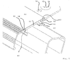
- Fig. 3 It can be seen that the tube 40 projects beyond the step 10 laterally.
- the tube 40 is - as already stated - introduced into the spars of the ladder and flanged end in a conventional manner to ensure the strength of the ladder.
- the step 10 terminates at its rear end in inclined surfaces 82 and 84, which reduces the risk of injury from sharp-edged portions of the step.
- the step 10 extends in the same way with its tread surface 12 over the entire width and has a first part with the embossments 14 to 18 and a second part with the plastic profile 52.
- the front part 46 adjoins the plastic profile 52 at the front and the apron 48 at the front.
- Out Fig. 5 a level 10 detail is visible.
- Like reference numerals indicate similar parts here as well as in the other figures.
- the locking tongues 64 and 66 abut against the support flanges 42 and 44. This supports in addition to the support of the end flanges 60 and 62 on the support flanges 56 and 58, the plastic profile 52 at the stage from the rest.
- Fig. 6 This is also out Fig. 6 seen.
- Grains 90 can be seen, which are embedded in the top of the plastic profile 52. These grains are not shown in the further figures for the sake of simplicity of illustration.
Landscapes
- Engineering & Computer Science (AREA)
- Mechanical Engineering (AREA)
- Ladders (AREA)
- Footwear And Its Accessory, Manufacturing Method And Apparatuses (AREA)
Priority Applications (1)
| Application Number | Priority Date | Filing Date | Title |
|---|---|---|---|
| PL17171244T PL3246509T3 (pl) | 2016-05-19 | 2017-05-16 | Drabina |
Applications Claiming Priority (1)
| Application Number | Priority Date | Filing Date | Title |
|---|---|---|---|
| DE202016102665.2U DE202016102665U1 (de) | 2016-05-19 | 2016-05-19 | Leiter |
Publications (2)
| Publication Number | Publication Date |
|---|---|
| EP3246509A1 EP3246509A1 (de) | 2017-11-22 |
| EP3246509B1 true EP3246509B1 (de) | 2019-01-09 |
Family
ID=56293463
Family Applications (1)
| Application Number | Title | Priority Date | Filing Date |
|---|---|---|---|
| EP17171244.1A Active EP3246509B1 (de) | 2016-05-19 | 2017-05-16 | Leiter |
Country Status (6)
| Country | Link |
|---|---|
| EP (1) | EP3246509B1 (pl) |
| DE (1) | DE202016102665U1 (pl) |
| DK (1) | DK3246509T3 (pl) |
| ES (1) | ES2719581T3 (pl) |
| HU (1) | HUE042588T2 (pl) |
| PL (1) | PL3246509T3 (pl) |
Cited By (1)
| Publication number | Priority date | Publication date | Assignee | Title |
|---|---|---|---|---|
| WO2021150611A1 (en) * | 2020-01-20 | 2021-07-29 | Little Giant Ladder Systems, Llc | Ladders and ladder rungs |
Family Cites Families (7)
| Publication number | Priority date | Publication date | Assignee | Title |
|---|---|---|---|---|
| DE8209895U1 (de) | 1982-04-06 | 1982-09-16 | Kümmerlin, Walter, 7120 Bietigheim-Bissingen | Bockleiter |
| DE20010298U1 (de) * | 2000-06-08 | 2000-08-17 | Zarges Leichtbau Gmbh, 82362 Weilheim | Stufe oder Sprosse sowie Leiter |
| FR2827905B1 (fr) * | 2001-07-27 | 2004-06-18 | Henri Monte | Echelles securisees |
| ITMO20020368A1 (it) * | 2002-12-30 | 2004-06-30 | Lo Scalino S R L | Mezzi di finitura perfezionati. |
| DE202004002872U1 (de) | 2004-02-25 | 2004-04-29 | Zarges Gmbh & Co Kg | Leiter |
| US6994185B1 (en) | 2004-12-23 | 2006-02-07 | Hertel Ryan W | Ladder rung pad assembly |
| DE102009053005A1 (de) * | 2009-11-16 | 2012-01-19 | Günter Überall | Verbindungssysteme für Sprossen-Profile mit Holm-Profilen |
-
2016
- 2016-05-19 DE DE202016102665.2U patent/DE202016102665U1/de not_active Expired - Lifetime
-
2017
- 2017-05-16 ES ES17171244T patent/ES2719581T3/es active Active
- 2017-05-16 HU HUE17171244A patent/HUE042588T2/hu unknown
- 2017-05-16 DK DK17171244.1T patent/DK3246509T3/en active
- 2017-05-16 EP EP17171244.1A patent/EP3246509B1/de active Active
- 2017-05-16 PL PL17171244T patent/PL3246509T3/pl unknown
Non-Patent Citations (1)
| Title |
|---|
| None * |
Cited By (2)
| Publication number | Priority date | Publication date | Assignee | Title |
|---|---|---|---|---|
| WO2021150611A1 (en) * | 2020-01-20 | 2021-07-29 | Little Giant Ladder Systems, Llc | Ladders and ladder rungs |
| US12529263B2 (en) | 2020-01-20 | 2026-01-20 | Little Giant Ladder Systems, Llc | Ladders and ladder rungs |
Also Published As
| Publication number | Publication date |
|---|---|
| DE202016102665U1 (de) | 2016-06-10 |
| DK3246509T3 (en) | 2019-04-15 |
| EP3246509A1 (de) | 2017-11-22 |
| ES2719581T3 (es) | 2019-07-11 |
| HUE042588T2 (hu) | 2019-07-29 |
| PL3246509T3 (pl) | 2019-10-31 |
Similar Documents
| Publication | Publication Date | Title |
|---|---|---|
| DE69127371T2 (de) | Montageelement für fassadenfliesen | |
| DE102014101322B4 (de) | Abdeckrost | |
| DE102006012867A1 (de) | Schuh, insbesondere Sportschuh | |
| EP1493880B1 (de) | Fussbodenleiste | |
| DE9301324U1 (de) | Halter | |
| DE202014105895U1 (de) | Einlage für ein Spülenbecken | |
| EP1036892B1 (de) | Antrittsprofil aus Metall | |
| EP3246509B1 (de) | Leiter | |
| EP0258877B1 (de) | Strangförmiges Dichtungsprofil | |
| EP2110194A2 (de) | Sägeblatt und Handsäge | |
| DE3308511C2 (pl) | ||
| DE10347409B4 (de) | Bremsbelagträgerplatte einer Fahrradscheibenbremse | |
| DE4125780C2 (de) | Leiter, insbesondere für Fahrzeuge | |
| EP3219895A1 (de) | Schiebetüranordnung und schiebeflügel einer schiebetüranordnung | |
| EP2708670A2 (de) | Bodenrost | |
| DE10300315B4 (de) | Bodenbelag mit schmutzabstreifender Wirkung | |
| AT524857B1 (de) | Standvorrichtung | |
| DE10320536B4 (de) | Crimpkralle eines elektrischen Kontaktelements | |
| AT515082B1 (de) | Fußabstreifmatte | |
| EP4020730B1 (de) | Schacht mit einer bodenplatte und bodenplatte für einen kunststoffschacht | |
| DE8808116U1 (de) | Wärmegedämmtes Verbundprofil für Fenster u.dgl. | |
| DE20010298U1 (de) | Stufe oder Sprosse sowie Leiter | |
| DE20013238U1 (de) | Blechanordnung | |
| DE2340015C2 (de) | Kinderschuh sowie Schweiß-Stanz-Werkzeug zur Befestigung eines Gleitschutzfleckes an der Schuhsohle des Kinderschuhs | |
| DE7527838U (de) | Trittblech |
Legal Events
| Date | Code | Title | Description |
|---|---|---|---|
| PUAI | Public reference made under article 153(3) epc to a published international application that has entered the european phase |
Free format text: ORIGINAL CODE: 0009012 |
|
| STAA | Information on the status of an ep patent application or granted ep patent |
Free format text: STATUS: THE APPLICATION HAS BEEN PUBLISHED |
|
| AK | Designated contracting states |
Kind code of ref document: A1 Designated state(s): AL AT BE BG CH CY CZ DE DK EE ES FI FR GB GR HR HU IE IS IT LI LT LU LV MC MK MT NL NO PL PT RO RS SE SI SK SM TR |
|
| AX | Request for extension of the european patent |
Extension state: BA ME |
|
| RIN1 | Information on inventor provided before grant (corrected) |
Inventor name: ELERSCHMALZ, ANDREAS Inventor name: UEBLACKER, RAINER |
|
| STAA | Information on the status of an ep patent application or granted ep patent |
Free format text: STATUS: REQUEST FOR EXAMINATION WAS MADE |
|
| 17P | Request for examination filed |
Effective date: 20180112 |
|
| RBV | Designated contracting states (corrected) |
Designated state(s): AL AT BE BG CH CY CZ DE DK EE ES FI FR GB GR HR HU IE IS IT LI LT LU LV MC MK MT NL NO PL PT RO RS SE SI SK SM TR |
|
| GRAP | Despatch of communication of intention to grant a patent |
Free format text: ORIGINAL CODE: EPIDOSNIGR1 |
|
| STAA | Information on the status of an ep patent application or granted ep patent |
Free format text: STATUS: GRANT OF PATENT IS INTENDED |
|
| INTG | Intention to grant announced |
Effective date: 20180717 |
|
| GRAS | Grant fee paid |
Free format text: ORIGINAL CODE: EPIDOSNIGR3 |
|
| GRAA | (expected) grant |
Free format text: ORIGINAL CODE: 0009210 |
|
| STAA | Information on the status of an ep patent application or granted ep patent |
Free format text: STATUS: THE PATENT HAS BEEN GRANTED |
|
| AK | Designated contracting states |
Kind code of ref document: B1 Designated state(s): AL AT BE BG CH CY CZ DE DK EE ES FI FR GB GR HR HU IE IS IT LI LT LU LV MC MK MT NL NO PL PT RO RS SE SI SK SM TR |
|
| REG | Reference to a national code |
Ref country code: GB Ref legal event code: FG4D Free format text: NOT ENGLISH |
|
| REG | Reference to a national code |
Ref country code: CH Ref legal event code: EP Ref country code: AT Ref legal event code: REF Ref document number: 1087517 Country of ref document: AT Kind code of ref document: T Effective date: 20190115 |
|
| REG | Reference to a national code |
Ref country code: IE Ref legal event code: FG4D Free format text: LANGUAGE OF EP DOCUMENT: GERMAN |
|
| REG | Reference to a national code |
Ref country code: DE Ref legal event code: R096 Ref document number: 502017000643 Country of ref document: DE |
|
| REG | Reference to a national code |
Ref country code: CH Ref legal event code: NV Representative=s name: KELLER AND PARTNER PATENTANWAELTE AG, CH Ref country code: DK Ref legal event code: T3 Effective date: 20190408 |
|
| REG | Reference to a national code |
Ref country code: SE Ref legal event code: TRGR |
|
| REG | Reference to a national code |
Ref country code: NL Ref legal event code: FP |
|
| REG | Reference to a national code |
Ref country code: LT Ref legal event code: MG4D |
|
| REG | Reference to a national code |
Ref country code: NO Ref legal event code: T2 Effective date: 20190109 |
|
| REG | Reference to a national code |
Ref country code: ES Ref legal event code: FG2A Ref document number: 2719581 Country of ref document: ES Kind code of ref document: T3 Effective date: 20190711 |
|
| REG | Reference to a national code |
Ref country code: HU Ref legal event code: AG4A Ref document number: E042588 Country of ref document: HU |
|
| PG25 | Lapsed in a contracting state [announced via postgrant information from national office to epo] |
Ref country code: PT Free format text: LAPSE BECAUSE OF FAILURE TO SUBMIT A TRANSLATION OF THE DESCRIPTION OR TO PAY THE FEE WITHIN THE PRESCRIBED TIME-LIMIT Effective date: 20190509 Ref country code: LT Free format text: LAPSE BECAUSE OF FAILURE TO SUBMIT A TRANSLATION OF THE DESCRIPTION OR TO PAY THE FEE WITHIN THE PRESCRIBED TIME-LIMIT Effective date: 20190109 |
|
| PG25 | Lapsed in a contracting state [announced via postgrant information from national office to epo] |
Ref country code: IS Free format text: LAPSE BECAUSE OF FAILURE TO SUBMIT A TRANSLATION OF THE DESCRIPTION OR TO PAY THE FEE WITHIN THE PRESCRIBED TIME-LIMIT Effective date: 20190509 Ref country code: HR Free format text: LAPSE BECAUSE OF FAILURE TO SUBMIT A TRANSLATION OF THE DESCRIPTION OR TO PAY THE FEE WITHIN THE PRESCRIBED TIME-LIMIT Effective date: 20190109 Ref country code: RS Free format text: LAPSE BECAUSE OF FAILURE TO SUBMIT A TRANSLATION OF THE DESCRIPTION OR TO PAY THE FEE WITHIN THE PRESCRIBED TIME-LIMIT Effective date: 20190109 Ref country code: LV Free format text: LAPSE BECAUSE OF FAILURE TO SUBMIT A TRANSLATION OF THE DESCRIPTION OR TO PAY THE FEE WITHIN THE PRESCRIBED TIME-LIMIT Effective date: 20190109 Ref country code: BG Free format text: LAPSE BECAUSE OF FAILURE TO SUBMIT A TRANSLATION OF THE DESCRIPTION OR TO PAY THE FEE WITHIN THE PRESCRIBED TIME-LIMIT Effective date: 20190409 Ref country code: GR Free format text: LAPSE BECAUSE OF FAILURE TO SUBMIT A TRANSLATION OF THE DESCRIPTION OR TO PAY THE FEE WITHIN THE PRESCRIBED TIME-LIMIT Effective date: 20190410 |
|
| REG | Reference to a national code |
Ref country code: DE Ref legal event code: R097 Ref document number: 502017000643 Country of ref document: DE |
|
| PG25 | Lapsed in a contracting state [announced via postgrant information from national office to epo] |
Ref country code: AL Free format text: LAPSE BECAUSE OF FAILURE TO SUBMIT A TRANSLATION OF THE DESCRIPTION OR TO PAY THE FEE WITHIN THE PRESCRIBED TIME-LIMIT Effective date: 20190109 Ref country code: IT Free format text: LAPSE BECAUSE OF FAILURE TO SUBMIT A TRANSLATION OF THE DESCRIPTION OR TO PAY THE FEE WITHIN THE PRESCRIBED TIME-LIMIT Effective date: 20190109 Ref country code: RO Free format text: LAPSE BECAUSE OF FAILURE TO SUBMIT A TRANSLATION OF THE DESCRIPTION OR TO PAY THE FEE WITHIN THE PRESCRIBED TIME-LIMIT Effective date: 20190109 Ref country code: CZ Free format text: LAPSE BECAUSE OF FAILURE TO SUBMIT A TRANSLATION OF THE DESCRIPTION OR TO PAY THE FEE WITHIN THE PRESCRIBED TIME-LIMIT Effective date: 20190109 Ref country code: EE Free format text: LAPSE BECAUSE OF FAILURE TO SUBMIT A TRANSLATION OF THE DESCRIPTION OR TO PAY THE FEE WITHIN THE PRESCRIBED TIME-LIMIT Effective date: 20190109 Ref country code: SK Free format text: LAPSE BECAUSE OF FAILURE TO SUBMIT A TRANSLATION OF THE DESCRIPTION OR TO PAY THE FEE WITHIN THE PRESCRIBED TIME-LIMIT Effective date: 20190109 |
|
| PLBE | No opposition filed within time limit |
Free format text: ORIGINAL CODE: 0009261 |
|
| STAA | Information on the status of an ep patent application or granted ep patent |
Free format text: STATUS: NO OPPOSITION FILED WITHIN TIME LIMIT |
|
| 26N | No opposition filed |
Effective date: 20191010 |
|
| PG25 | Lapsed in a contracting state [announced via postgrant information from national office to epo] |
Ref country code: MC Free format text: LAPSE BECAUSE OF FAILURE TO SUBMIT A TRANSLATION OF THE DESCRIPTION OR TO PAY THE FEE WITHIN THE PRESCRIBED TIME-LIMIT Effective date: 20190109 |
|
| PG25 | Lapsed in a contracting state [announced via postgrant information from national office to epo] |
Ref country code: LU Free format text: LAPSE BECAUSE OF NON-PAYMENT OF DUE FEES Effective date: 20190516 Ref country code: SI Free format text: LAPSE BECAUSE OF FAILURE TO SUBMIT A TRANSLATION OF THE DESCRIPTION OR TO PAY THE FEE WITHIN THE PRESCRIBED TIME-LIMIT Effective date: 20190109 |
|
| PG25 | Lapsed in a contracting state [announced via postgrant information from national office to epo] |
Ref country code: TR Free format text: LAPSE BECAUSE OF FAILURE TO SUBMIT A TRANSLATION OF THE DESCRIPTION OR TO PAY THE FEE WITHIN THE PRESCRIBED TIME-LIMIT Effective date: 20190109 |
|
| PG25 | Lapsed in a contracting state [announced via postgrant information from national office to epo] |
Ref country code: IE Free format text: LAPSE BECAUSE OF NON-PAYMENT OF DUE FEES Effective date: 20190516 |
|
| REG | Reference to a national code |
Ref country code: CH Ref legal event code: PFA Owner name: ZARGES GMBH, DE Free format text: FORMER OWNER: ZARGES GMBH, DE |
|
| PG25 | Lapsed in a contracting state [announced via postgrant information from national office to epo] |
Ref country code: CY Free format text: LAPSE BECAUSE OF FAILURE TO SUBMIT A TRANSLATION OF THE DESCRIPTION OR TO PAY THE FEE WITHIN THE PRESCRIBED TIME-LIMIT Effective date: 20190109 |
|
| PG25 | Lapsed in a contracting state [announced via postgrant information from national office to epo] |
Ref country code: SM Free format text: LAPSE BECAUSE OF FAILURE TO SUBMIT A TRANSLATION OF THE DESCRIPTION OR TO PAY THE FEE WITHIN THE PRESCRIBED TIME-LIMIT Effective date: 20190109 |
|
| PG25 | Lapsed in a contracting state [announced via postgrant information from national office to epo] |
Ref country code: MT Free format text: LAPSE BECAUSE OF FAILURE TO SUBMIT A TRANSLATION OF THE DESCRIPTION OR TO PAY THE FEE WITHIN THE PRESCRIBED TIME-LIMIT Effective date: 20190109 |
|
| PG25 | Lapsed in a contracting state [announced via postgrant information from national office to epo] |
Ref country code: MK Free format text: LAPSE BECAUSE OF FAILURE TO SUBMIT A TRANSLATION OF THE DESCRIPTION OR TO PAY THE FEE WITHIN THE PRESCRIBED TIME-LIMIT Effective date: 20190109 |
|
| P01 | Opt-out of the competence of the unified patent court (upc) registered |
Effective date: 20230530 |
|
| PGFP | Annual fee paid to national office [announced via postgrant information from national office to epo] |
Ref country code: NL Payment date: 20230525 Year of fee payment: 7 Ref country code: ES Payment date: 20230613 Year of fee payment: 7 Ref country code: DK Payment date: 20230524 Year of fee payment: 7 Ref country code: CH Payment date: 20230602 Year of fee payment: 7 |
|
| PGFP | Annual fee paid to national office [announced via postgrant information from national office to epo] |
Ref country code: PL Payment date: 20230508 Year of fee payment: 7 Ref country code: FI Payment date: 20230526 Year of fee payment: 7 Ref country code: AT Payment date: 20230508 Year of fee payment: 7 |
|
| PGFP | Annual fee paid to national office [announced via postgrant information from national office to epo] |
Ref country code: BE Payment date: 20230525 Year of fee payment: 7 |
|
| REG | Reference to a national code |
Ref country code: DE Ref legal event code: R082 Ref document number: 502017000643 Country of ref document: DE Representative=s name: SKM-IP SCHMID KRAUSS KUTTENKEULER MALESCHA SCH, DE |
|
| REG | Reference to a national code |
Ref country code: CH Ref legal event code: PL |
|
| REG | Reference to a national code |
Ref country code: DK Ref legal event code: EBP Effective date: 20240531 |
|
| REG | Reference to a national code |
Ref country code: NL Ref legal event code: MM Effective date: 20240601 |
|
| REG | Reference to a national code |
Ref country code: AT Ref legal event code: MM01 Ref document number: 1087517 Country of ref document: AT Kind code of ref document: T Effective date: 20240516 |
|
| PG25 | Lapsed in a contracting state [announced via postgrant information from national office to epo] |
Ref country code: FI Free format text: LAPSE BECAUSE OF NON-PAYMENT OF DUE FEES Effective date: 20240516 |
|
| PG25 | Lapsed in a contracting state [announced via postgrant information from national office to epo] |
Ref country code: AT Free format text: LAPSE BECAUSE OF NON-PAYMENT OF DUE FEES Effective date: 20240516 |
|
| PG25 | Lapsed in a contracting state [announced via postgrant information from national office to epo] |
Ref country code: FI Free format text: LAPSE BECAUSE OF NON-PAYMENT OF DUE FEES Effective date: 20240516 Ref country code: AT Free format text: LAPSE BECAUSE OF NON-PAYMENT OF DUE FEES Effective date: 20240516 Ref country code: CH Free format text: LAPSE BECAUSE OF NON-PAYMENT OF DUE FEES Effective date: 20240531 |
|
| PG25 | Lapsed in a contracting state [announced via postgrant information from national office to epo] |
Ref country code: NL Free format text: LAPSE BECAUSE OF NON-PAYMENT OF DUE FEES Effective date: 20240601 |
|
| REG | Reference to a national code |
Ref country code: BE Ref legal event code: MM Effective date: 20240531 |
|
| PGFP | Annual fee paid to national office [announced via postgrant information from national office to epo] |
Ref country code: SE Payment date: 20250310 Year of fee payment: 9 |
|
| PG25 | Lapsed in a contracting state [announced via postgrant information from national office to epo] |
Ref country code: DK Free format text: LAPSE BECAUSE OF NON-PAYMENT OF DUE FEES Effective date: 20240531 |
|
| PG25 | Lapsed in a contracting state [announced via postgrant information from national office to epo] |
Ref country code: BE Free format text: LAPSE BECAUSE OF NON-PAYMENT OF DUE FEES Effective date: 20240531 |
|
| PGFP | Annual fee paid to national office [announced via postgrant information from national office to epo] |
Ref country code: FR Payment date: 20250310 Year of fee payment: 9 |
|
| PGFP | Annual fee paid to national office [announced via postgrant information from national office to epo] |
Ref country code: GB Payment date: 20250327 Year of fee payment: 9 |
|
| REG | Reference to a national code |
Ref country code: ES Ref legal event code: FD2A Effective date: 20250630 |
|
| PG25 | Lapsed in a contracting state [announced via postgrant information from national office to epo] |
Ref country code: PL Free format text: LAPSE BECAUSE OF NON-PAYMENT OF DUE FEES Effective date: 20240516 |
|
| PGFP | Annual fee paid to national office [announced via postgrant information from national office to epo] |
Ref country code: DE Payment date: 20250319 Year of fee payment: 9 |
|
| PG25 | Lapsed in a contracting state [announced via postgrant information from national office to epo] |
Ref country code: ES Free format text: LAPSE BECAUSE OF NON-PAYMENT OF DUE FEES Effective date: 20240517 |
|
| PGFP | Annual fee paid to national office [announced via postgrant information from national office to epo] |
Ref country code: HU Payment date: 20250415 Year of fee payment: 9 Ref country code: NO Payment date: 20250509 Year of fee payment: 9 |