EP3244775B1 - Dispositif d'entrainement pour meuble - Google Patents
Dispositif d'entrainement pour meuble Download PDFInfo
- Publication number
- EP3244775B1 EP3244775B1 EP15817050.6A EP15817050A EP3244775B1 EP 3244775 B1 EP3244775 B1 EP 3244775B1 EP 15817050 A EP15817050 A EP 15817050A EP 3244775 B1 EP3244775 B1 EP 3244775B1
- Authority
- EP
- European Patent Office
- Prior art keywords
- bend
- furniture drive
- driver
- furniture
- entrainment member
- Prior art date
- Legal status (The legal status is an assumption and is not a legal conclusion. Google has not performed a legal analysis and makes no representation as to the accuracy of the status listed.)
- Active
Links
- 230000008878 coupling Effects 0.000 claims description 17
- 238000010168 coupling process Methods 0.000 claims description 17
- 238000005859 coupling reaction Methods 0.000 claims description 17
- 238000004146 energy storage Methods 0.000 description 5
- 238000000605 extraction Methods 0.000 description 4
- 238000013016 damping Methods 0.000 description 3
- 230000009471 action Effects 0.000 description 2
- 230000008901 benefit Effects 0.000 description 2
- 230000003993 interaction Effects 0.000 description 2
- 230000007246 mechanism Effects 0.000 description 2
- 230000001133 acceleration Effects 0.000 description 1
- 230000002238 attenuated effect Effects 0.000 description 1
- 230000000903 blocking effect Effects 0.000 description 1
- 230000001419 dependent effect Effects 0.000 description 1
- 238000004519 manufacturing process Methods 0.000 description 1
- 230000036316 preload Effects 0.000 description 1
- 230000009467 reduction Effects 0.000 description 1
- 230000002040 relaxant effect Effects 0.000 description 1
- 230000001360 synchronised effect Effects 0.000 description 1
- 230000001960 triggered effect Effects 0.000 description 1
Images


Classifications
-
- A—HUMAN NECESSITIES
- A47—FURNITURE; DOMESTIC ARTICLES OR APPLIANCES; COFFEE MILLS; SPICE MILLS; SUCTION CLEANERS IN GENERAL
- A47B—TABLES; DESKS; OFFICE FURNITURE; CABINETS; DRAWERS; GENERAL DETAILS OF FURNITURE
- A47B88/00—Drawers for tables, cabinets or like furniture; Guides for drawers
- A47B88/40—Sliding drawers; Slides or guides therefor
- A47B88/453—Actuated drawers
- A47B88/46—Actuated drawers operated by mechanically-stored energy, e.g. by springs
- A47B88/467—Actuated drawers operated by mechanically-stored energy, e.g. by springs self-closing
-
- A—HUMAN NECESSITIES
- A47—FURNITURE; DOMESTIC ARTICLES OR APPLIANCES; COFFEE MILLS; SPICE MILLS; SUCTION CLEANERS IN GENERAL
- A47B—TABLES; DESKS; OFFICE FURNITURE; CABINETS; DRAWERS; GENERAL DETAILS OF FURNITURE
- A47B88/00—Drawers for tables, cabinets or like furniture; Guides for drawers
- A47B88/40—Sliding drawers; Slides or guides therefor
- A47B88/473—Braking devices, e.g. linear or rotational dampers or friction brakes; Buffers; End stops
-
- A—HUMAN NECESSITIES
- A47—FURNITURE; DOMESTIC ARTICLES OR APPLIANCES; COFFEE MILLS; SPICE MILLS; SUCTION CLEANERS IN GENERAL
- A47B—TABLES; DESKS; OFFICE FURNITURE; CABINETS; DRAWERS; GENERAL DETAILS OF FURNITURE
- A47B88/00—Drawers for tables, cabinets or like furniture; Guides for drawers
- A47B88/40—Sliding drawers; Slides or guides therefor
- A47B88/497—Sliding drawers; Slides or guides therefor with other guiding mechanisms, e.g. scissor mechanisms
-
- E—FIXED CONSTRUCTIONS
- E05—LOCKS; KEYS; WINDOW OR DOOR FITTINGS; SAFES
- E05F—DEVICES FOR MOVING WINGS INTO OPEN OR CLOSED POSITION; CHECKS FOR WINGS; WING FITTINGS NOT OTHERWISE PROVIDED FOR, CONCERNED WITH THE FUNCTIONING OF THE WING
- E05F1/00—Closers or openers for wings, not otherwise provided for in this subclass
- E05F1/08—Closers or openers for wings, not otherwise provided for in this subclass spring-actuated, e.g. for horizontally sliding wings
- E05F1/16—Closers or openers for wings, not otherwise provided for in this subclass spring-actuated, e.g. for horizontally sliding wings for sliding wings
-
- F—MECHANICAL ENGINEERING; LIGHTING; HEATING; WEAPONS; BLASTING
- F03—MACHINES OR ENGINES FOR LIQUIDS; WIND, SPRING, OR WEIGHT MOTORS; PRODUCING MECHANICAL POWER OR A REACTIVE PROPULSIVE THRUST, NOT OTHERWISE PROVIDED FOR
- F03G—SPRING, WEIGHT, INERTIA OR LIKE MOTORS; MECHANICAL-POWER PRODUCING DEVICES OR MECHANISMS, NOT OTHERWISE PROVIDED FOR OR USING ENERGY SOURCES NOT OTHERWISE PROVIDED FOR
- F03G1/00—Spring motors
- F03G1/06—Other parts or details
- F03G1/10—Other parts or details for producing output movement other than rotary, e.g. vibratory
-
- F—MECHANICAL ENGINEERING; LIGHTING; HEATING; WEAPONS; BLASTING
- F16—ENGINEERING ELEMENTS AND UNITS; GENERAL MEASURES FOR PRODUCING AND MAINTAINING EFFECTIVE FUNCTIONING OF MACHINES OR INSTALLATIONS; THERMAL INSULATION IN GENERAL
- F16C—SHAFTS; FLEXIBLE SHAFTS; ELEMENTS OR CRANKSHAFT MECHANISMS; ROTARY BODIES OTHER THAN GEARING ELEMENTS; BEARINGS
- F16C29/00—Bearings for parts moving only linearly
- F16C29/005—Guide rails or tracks for a linear bearing, i.e. adapted for movement of a carriage or bearing body there along
-
- E—FIXED CONSTRUCTIONS
- E05—LOCKS; KEYS; WINDOW OR DOOR FITTINGS; SAFES
- E05Y—INDEXING SCHEME RELATING TO HINGES OR OTHER SUSPENSION DEVICES FOR DOORS, WINDOWS OR WINGS AND DEVICES FOR MOVING WINGS INTO OPEN OR CLOSED POSITION, CHECKS FOR WINGS AND WING FITTINGS NOT OTHERWISE PROVIDED FOR, CONCERNED WITH THE FUNCTIONING OF THE WING
- E05Y2900/00—Application of doors, windows, wings or fittings thereof
- E05Y2900/20—Application of doors, windows, wings or fittings thereof for furnitures, e.g. cabinets
-
- F—MECHANICAL ENGINEERING; LIGHTING; HEATING; WEAPONS; BLASTING
- F16—ENGINEERING ELEMENTS AND UNITS; GENERAL MEASURES FOR PRODUCING AND MAINTAINING EFFECTIVE FUNCTIONING OF MACHINES OR INSTALLATIONS; THERMAL INSULATION IN GENERAL
- F16C—SHAFTS; FLEXIBLE SHAFTS; ELEMENTS OR CRANKSHAFT MECHANISMS; ROTARY BODIES OTHER THAN GEARING ELEMENTS; BEARINGS
- F16C2314/00—Personal or domestic articles, e.g. household appliances such as washing machines, dryers
- F16C2314/70—Furniture
- F16C2314/72—Drawers
Definitions
- the invention relates to an arrangement with a furniture drive of the type to be described and with an ejection device for ejecting the movable furniture part, through which the movable furniture part is ejected, starting from the closed position into an open position. Furthermore, the invention relates to a drawer pull-out with such a furniture drive or with an arrangement of the type mentioned above.
- Furniture drives in the form of collection devices come in particular with drawers or sliding doors are used, which are freely movable over a large part of their pull-out area and captured only at the end of the closing movement of the catcher of the collection device and fed by spring force in the closed end position.
- a user When the movable furniture part is opened, a user first has to apply a force against the spring resistance by applying manual pull to the movable furniture part until the driver moves into a bend in the guide track after a predetermined distance, whereby the movable furniture part is decoupled from the driver.
- the driver is releasably locked by the turn of the guideway in a self-locking locked parking position, wherein the spring device is in a tensioned state and thus in a ready position for the next retracting operation.
- the pull-in section of the movable furniture part up to the closed end position is constant.
- the driver can be moved along the first or second guide track.
- the production of the driver is designed somewhat complex, because the adjusting means in the form of the pin is an inherent component of the driver.
- the driver is due to the sliding pin only one side (ie only on one side of the housing) feasible, so there is a risk of undesirable tilting of the driver. From the US 2008/231156 A1 another furniture drive is known, which discloses the preamble of claim 1.
- Object of the present invention is to provide a furniture drive of the type mentioned above while avoiding the above disadvantages. This is achieved by the features of claim 1. Further advantageous embodiments are specified in the dependent subclaims.
- the guide track has at least one second turn for detachable locking of the driver, wherein at least one movably mounted shift element is provided with a first and a second shift position, wherein the shift element blocks the first turn in the first shift position, so that the driver is retractable in the second turn and wherein the switching element in the second switching position releases the first turn, so that the driver is retractable in the first turn.
- the guideway has at least two bends spaced apart from one another in the longitudinal direction of the housing for the purpose of releasably locking the housing Driver on, the retraction of the driver in these bends when opening the movable furniture part by a separate from the driver, movably mounted switching element is selectively controllable. In a first position of the switching element, the first turn is blocked, so that the driver is retractable in the second turn. In a second position of the switching element, however, the first turn is released, so that the driver enters this first turn.
- Due to the at least two turns of the driver is selectively releasably lockable to at least two mutually different positions relative to the housing, wherein the two different locking positions of the driver and two different long collection paths of the driver or two different spring forces are available for retracting the movable furniture part.
- the feed path of the driver or the force exerted on the movable furniture part of the spring device can be variably adjusted.
- a relatively short feed path is sufficient.
- the drawer remains in an open position due to their weight and the friction occurring already before reaching the closed end position.
- the switching element in the first switching position blocks the first turn by blocking, so that entry of the driver is prevented in the first turn.
- the switching element is thus positioned in the first switching position such that the first turn in the Pulling out of the driver by the switching element is at least partially blocked or blocked, and thus entry of the driver is prevented in this first turn.
- the switching element is arranged laterally next to the guide track and in the first switching position deflects the driver so that an entrance of the driver is prevented in the first turn.
- the switching element is thus in this embodiment laterally next to or outside of the guideway and prevents in the first switching position by deflection or deflection of moving in the withdrawal direction driver entry into the first turn.
- Such a furniture drive is equipped with an additional ejection device for ejecting the movable furniture part from the closed position to an open position.
- Such an ejection device often has at least one, preferably lockable, energy storage, which can be triggered by a touch-latch mechanism.
- touch-latch systems are used in particular when the movable furniture parts (for example, for aesthetic reasons) have no handle.
- the ejection device is unlocked by manual pressure or pulling exercise on the closed furniture part, whereupon the movably mounted furniture part is ejected by the force of the force accumulator (preferably an ejection spring) in an open position. A user can then move the slightly open furniture part by engaging behind (even without the presence of a handle) in the extension direction.
- the switching element can be switched, for example, by a manual actuation or by actuation of a tool between the first and the second switching position. According to one embodiment, it is alternatively also possible for the switching element to be switchable by mounting a discharge device for the ejection of the movable furniture part between the first and the second switching position, which is to be subsequently connected to the housing of the furniture drive.
- the switching element may alternatively also comprise an electromechanical switch or an electronic switch (for example a transistor).
- Fig. 1 shows a perspective view of a piece of furniture 1 with a furniture body 2, wherein movable furniture parts 3 in the form of drawers 3a are movably mounted on Schubladenauszieh Entryen 4 relative to the furniture body 2.
- the drawer pull-out guide 4 has a body rail 5 to be fastened to the furniture body 2 and at least one pull-out rail 6 movably mounted relative to the carcass rail 5.
- a furniture drive 7 By a furniture drive 7, the movable furniture part 3 is retractable in a closed position relative to the furniture body 2.
- an ejection device 8 is provided, through which the movable furniture part 3 can be ejected from the closed position into an open position.
- Fig. 2a shows a perspective view of the drawer pull-out guide 4 with the carcass rail 5 and the pull-out rail 6, between which an auszeltverinrnde center rail 11 is movably mounted.
- the drawer pull-out guide 4 is in the shown figure in the closed position, so that the pull-out rail 6 can be pulled out in the opening direction 12.
- the pull-out rail 6 has a U-profile in cross-section, wherein a housing 9 of the furniture drive 7 is mounted on a lateral leg 14 of the pull-out rail 6 via fastening means 10, preferably in the form of screws. By the furniture drive 7, the pull-6 is retractable towards the end of the closing movement in the closed end position.
- the furniture drive 7 has a relative to the housing 9 movably mounted switching element 15 which is switchable (preferably displaceable or rotatable) between at least two switching positions.
- a switching of the switching element 15 is a driver 30 ( Fig. 4a ) of the furniture drive 7 via at least two different lengths to the closed end position of the driver 30 retractable.
- the switching element 15 is in the first position, in which a long feed path for the driver 30 (and thus for the pull-out rail 6) is provided.
- Fig. 2b shows the in Fig. 2a circled area in an enlarged view.
- a hook 16 is provided on the pull-out rail 6, which protrudes in the mounted position into a hole arranged at the back of the drawer rear wall.
- a manually operable clutch lever 17 is provided, the locking edges 18 are releasably latched by the resilient design of the coupling lever 17 automatically with a fixed to the drawer 3a support rail.
- the housing 9 of the furniture drive 7 is also provided with a plurality of hooks 19 which can engage in corresponding recesses of the ejection device 8.
- At least one projection 21 is formed on the housing 9 of the furniture drive 7, which rests in the mounting position on the housing 22 of the ejection device 8.
- Fixed to the stationary carcass rail 5 is an ejection driver 13, which can be coupled to the ejection device 8.
- Fig. 3a shows the drawer extension guide 4 with the attached to the pull-6 6 furniture drive 7.
- a housing 22 of the ejection device 8 is releasably secure.
- the ejection device 8 has an adjusting wheel 24, by means of which the position of the drawer 3a is variably adjustable in the closed position.
- the ejection device 8 has a rotatable part 25 by which a movement of the ejection device 8 can be synchronized via a synchronization rod (not shown) with a movement of a second ejection device 8 located opposite the furniture body 2.
- Fig. 3a and in the enlarged detail view according to FIG Fig. 3b is the housing 22 of the ejector 8 relative to the housing 9 of the furniture drive 7 on the in Fig. 2a shown prepositioned hook 19, wherein the housing 22 of the ejection device 8 has a stop 23 for actuating the switching element 15.
- the housing 22 of the ejection device 8 can be moved by manual pressure in the direction of the arrow shown relative to the housing 9 of the furniture drive 7, so that the stop 23, the switching element 15, starting from the first switching position to the right in the second switching position Fig. 3c shifts.
- the housing 22 of the ejection device 8 can be moved by manual pressure in the direction of the arrow shown relative to the housing 9 of the furniture drive 7, so that the stop 23, the switching element 15, starting from the first switching position to the right in the second switching position Fig. 3c shifts.
- 3c shown second switching position is a reduced compared to the first switching position Einzugsweg the driver 30 (FIG. Fig. 4a ) of the furniture drive 7 so that the energy storage of the ejection device 8 when ejecting the drawer 3a from the closed position only a shortened Einzugsweg the driver 30 and a lower force of the spring device 29 must overcome.
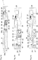
- Fig. 4a shows a side view of the furniture drive 7, wherein the housing 9, a guide track 26 with at least two spaced from each other in the longitudinal direction of the housing 9 bends 27, 28 is arranged or formed.
- the movably mounted on the housing 9 switching element 15 is thereby in the first switching position, so that the first turn 27 is blocked.
- An acted upon by a spring device 29 driver 30 which is releasably coupled to the movable furniture part 3 is guided via at least one guide member 31 along the guide rail 26 slidably.
- the spring device 29, which preferably comprises at least one tension spring, is fastened to the housing 9 via a first fastening point 39a and to a spring holder 33 separate from the catch 30 via a second fastening point 39b, the spring holder 33 being connected to the catch 30 via a coupling device 35 (FIG. Fig. 4c ) communicates in a coupled motion.
- the driver 30 has a notch 38 for releasable coupling with a attached to the pull-6 or the movable furniture part 3 coupling element (preferably a driving pin).
- the two bends 27, 28 of the driver 30 is selectively releasably lockable at two different positions relative to the housing 9, wherein the spring device 29 is less tensioned in the position in which the driver 30 is releasably locked to the first bend 27, as in the position in which the driver 30 is releasably locked to the second bend 28.
- the first bend 27 and the second bend 28 run parallel to each other at least in sections.
- the switching element 15 can be pressed by a separate spring device 29 from the spring element 32 in the first, the turn 27 obstructing switching position, so for the furniture drive 7 by default, a long feed path for the driver 30 is available.
- the spring-assisted retraction movement of the driver 30 (and thus that of the movable furniture part 3) can be damped by a damping device 37, preferably a hydraulic piston-cylinder unit.
- Fig. 4b shows the in Fig. 4a framed area in an enlarged view.
- the bolt 45 is arranged on the spring holder 33 and is slidably guided along a slot 46 of the slider 47.
- the tilting part 36 has at least one guide part 40, which is displaceably mounted along a control cam 41.
- Fig. 4c shows the detail view according to Fig. 4b , wherein the slot 46 of the slider 47 is hidden.
- the coupling device 35 comprises the pivotable tilting part 36, wherein a first toothing 42 of the tilting part 36 cooperates with a second toothing 43 of the slider 47.
- the charging of the spring device 29 is thereby carried out with a reduced effort, the unwanted spring break and an associated, excessive acceleration of the movable furniture part 3 when uncoupling the driver 30 from the movable furniture part 3 can be prevented.
- the control cam 41 provided for guiding the tilting part 36 has a first section 41a and a second section 41b, which are connected to one another via an apex 44.
- Fig. 5a-5d show the extraction process of the driver 30 in chronological order.
- the driver 30 is connected to the movable slide 47 via a pivot axis 48, wherein the toothing 43 of the slider 47 meshes with the toothing 42 of the tilting part 36.
- the tilting part 36 is pivotally connected to the spring holder 33, which is connected via the attachment point 39b with the spring device 29 in connection.
- the tilting part 36 has a guide part 40 which can be guided along the control cam 41.
- the switching element 15 in the first switching position, so that the first bend 27 is blocked for entry of the driver 30 so that the driver 30 is guided along the longer guide track 26 and then releasably lockable with the second bend 28.
- Fig. 5b the driver 30 is in a slightly extended position, wherein the guide member 40 of the tilting member 36 is located at the apex 44 of the control cam 41.
- the attachment point 39b of the spring device 29 on the spring holder 33 initially moves at the same speed as the catch 30 traveling in the withdrawal direction.
- Fig. 5c the driver 30 is further extended, wherein the guide member 40 of the tilting member 36 in the first switching position of the switching element 15 along the portions 41 a and 41 b of the control cam 41 is feasible.
- the attachment point 39b begins to slow down by the interaction of the teeth 42, 43 and by a pivoting movement of the tilting member 36 continuously, so that the spring device 29 is not stretched to the maximum spring deflection.
- Fig. 5d was the driver 30 pivoted by the interaction with the second bend 28 about the pivot axis 48, so that the driver 30 is releasably locked to the second bend 28 and thus is in a self-locking locked standby position.
- a (not shown) coupling element of the pull-6 is released, so that the movable furniture part 3 is further moved uncoupled in the direction of the open position.
- the driver 30 again detach from the self-locking locked ready position, whereupon the driver 30 is retractable together with the movable furniture part 3 by the force of the spring device 29 in the closed position.
- a damping device 37 with a cylinder 37a and a relatively movable piston rod 37b, the free end of the movable slide 47 is applied loosely, this spring-assisted retraction movement of the driver 30 can run attenuated.
- Fig. 6a shows the furniture drive 7, wherein the relative to the housing 9 slidably mounted switching element 15 has been moved to the second switching position, ie, the first guide rail 27 is released for entry of the driver 30.
- the switching of the switching element 15 can be purely mechanical, preferably by the subsequent assembly of the ejection device 8 (FIG. Fig. 3b, 3c ) on the housing 9 of the furniture drive 7. It can be seen that the spring element 32 is in a compressed state, so that when disassembling the ejection device 8, the switching element 15 is automatically moved back by the force of the relaxing spring element 32 in the first switching position.
- Fig. 6a is the driver 30 in the retracted end position, wherein the spring device 29 is relaxed.
- Fig. 6b shows that the driver 30 by manual Ceiffeübung on the movable furniture part 3 initially along a linearly extending portion 26 a ( Fig. 8 ) of the guide track 26 is movable.
- the toothing 42 cooperates with the toothing 43 of the movable slide 47, a Kraftabsenkmechanik is realized, wherein the attachment point 39b of the spring device 29 on the spring holder 33 when pulling out of the driver 30 relative to the position of the proceeding in the opening direction Driver 30 falls behind.
- the tilting part 36 has a guide part 40, which along the control cam 41 (FIG. Fig. 6a ) is guided displaceably.
- Fig. 6c shows one compared to Fig. 6b by an asymmetric articulation of the spring device 29 at the attachment point 39b
- the guide member 30 of the driver 30 has the tendency to dodge laterally in the direction of the first bend 28 so that the driver 30 does not move further in the direction of the second bend 28 becomes.
- the first bend 27 and the second bend 28 can run parallel to each other at least in sections.
- the driver 30 is releasably locked to the first bend 27, wherein a coupling element connected to the pull-6 is released by the pivoting of the driver 30 about the pivot axis 48.
- the spring device 29 is less tensioned in the position shown in which the driver 39 is releasably locked to the first bend 27 than in the position in which the driver 30 is releasably locked to the second bend 28. Due to the at least two positions of the switching element 15 are at least two different-length intake paths of the driver 30 and at least two different retraction forces of the spring device 29 are available.
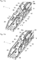
- Fig. 7 shows the furniture drive 7 in an exploded view.
- the housing 9 comprises two housing parts 9a and 9b to be connected to each other, on which the guide track 26 for the driver 30 with the two bends 27 and 28, which are spaced apart in the longitudinal direction of the housing 9, are formed.
- a cam 41 for the tilting part 36 is formed on the housing 9, which has a first portion 41 a and a second portion 41 b, which are connected to each other via the vertex 44.
- resilient holders 50a and 50b are provided on the housing 9, on which the cylinder 37a can be snapped on.
- the spring device 29 is fastened to the housing 9 via a first attachment point 39a and to the spring holder 33 via a second attachment point 39b, which is displaceably guided via a bolt 45 along a slot 46 of the slider 47.
- a tilting part 36 is connected to a toothing 42, which cooperates with a toothing 43 of the slide 47, not shown here.
- the driver 30 is connected to the slider 47 via a pivot axis 48 hingedly connected.
- the driver 30 has guide elements 31, by which the driver 30 along the guide rail 26 of the housing 9 slidably guided and over which the driver 30 with the two bends 27 and 28 is releasably locked.
- the driver 30 has a notch 38 for releasable coupling with the movable furniture part 3.
- the movable between two switching positions switching element 15 is disposed on a bearing element 49 and is pressed by the spring element 32 in the first switching position in which the first bend 27 is blocked. In this way, by default (ie without the attachment of the ejection device 8) is a longer Einzugsweg for the driver 30 is available.
- the separate from the driver 30 switching element 30 may also have a receptacle for a tool, wherein by switching the tool, the switching element 15 is adjustable between the two switching positions.
- the switching element 15 may also be formed in two or more parts, wherein a first part to be actuated is coupled in a motion-coupled manner to a second part obstructing the bend 27.
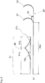
- Fig. 8 shows highly schematically the course of the guide track 26, starting from the retracted end position 51 of the driver 30 a linear travel 26a and at least two spaced apart from each other in the longitudinal direction bends 27 and 28 for releasably locking the driver 30 comprises.
- the control cam 41 for guiding the tilting part 36 comprises a first portion 41a and a second portion 41b, which are interconnected via the apex 44. If now two spaced bends 27 and 28 are provided, the control cam 41 would theoretically also have to include an additional third section 41c, which is spaced from the first section 41a in the longitudinal direction.
- the entrance of the tilting part 36 in the first section 41a or alternatively in the third section 41c would be controlled by an additional switching element 15a.
- an additional switching element 15a By the subsequent to the first portion 41 a second portion 41 b, it is possible to dispense with both the third portion 41 c and on the additional switching element 15 a, so that therefore a single switching element 15 both for the choice of bends 27, 28 and for the corresponding length of the control cam 41 is sufficient.
- the power reduction behaves in both travels of the driver 30 in the bends 27, 28 proportional to the path.
- the tilting part 36 is in the first switching position of the switching element 15, in which the first bend 27 is blocked, along the first portion 41 a and the second portion 41 b feasible. If, however, the switching element 15 is in the second switching position in which the first bend 27 is released, then the tilting part 36 is guided exclusively along the first portion 41a of the control cam 41.
- Fig. 9a shows a furniture drive 7 in a slightly modified embodiment, wherein the switching element 15 is arranged laterally next to the guide track 26 and in the first switching position the driver 30 deflects such that entry of the driver 30 is prevented in first bend 27.
- the movable switch element 15 in this embodiment is now laterally next to or behind outside the guide track 26.
- the shift element 15 has a movable projection which, in the first shift position (FIG. Fig. 9a ) of a Bottom 53 of the housing 9 projects and in the second switching position ( Fig.
- the switching element 15 can be switched between the first switching position and the second switching position by mounting and dismounting a discharge device 8 to be subsequently connected to the housing 9 of the furniture drive 7.
- Fig. 9b shows the furniture drive 7 with the switching element 15 in the second switching position, so that the driver 30 moves when pulling in the opening direction in the first turn 27.
- the driver 30 moves when pulling in the withdrawal direction 12 (and when the switching element 15 is in the second switching position) in the first turn 27, because the driver 30 by the force of the spring device 29 with a force across Extraction 12 is pressed against the side wall 54 of the guide track 26.
- Fig. 10a-10c show a portion of the furniture drive 7 with different positions of the driver 30 in the withdrawal 12.
- Fig. 10a is located on the housing 9 movably mounted switching element 15 in the first switching position, in which an entrance of the driver 30 is prevented in the first bend 27.
- the movable switching element 15 is arranged laterally next to the guide track 29 and deflects in the first switching position, the driver 30 from such that when pulling in the pull-12 a drive of the driver 30 in the first turn 27 is not possible.
- the driver 30 is thus - as in Fig. 10b apparent - past the first bend 27, whereupon the guide member 31 of the driver 30 enters the second bend 28 and thereby the driver 30 is tilted about the pivot axis 48.
- the movable furniture part 3 By tilting the driver 30 about the pivot axis 48, the movable furniture part 3 is decoupled from the driver 30 and can be further moved in the withdrawal direction 12. If the movable furniture part 3 is closed again, the driver 30 is released again from the locked position with the second bend 28 and pulled together with the movable furniture part 3 by the force of the spring device 29 in the closed position.
- FIG. 11a and 11b each show a portion of the furniture drive 7, wherein the housing 9 is movably mounted switching element 15 is in the second switching position. In the second switching position of the switching element 15 this is sunk so far that the switching element 15 does not hinder movement of the driver 30. Since the two guide elements 31 of the driver 30 are pressed by the force of the spring device 29 against the side wall 54 of the guide track 26, the driver 30 moves in a movement in the withdrawal direction 12 in the first bend 27 a. By retracting the guide elements 31 in the first turn of the driver 30 is rotated about the pivot axis 48 and are the movable furniture part 3 free. Fig. 11b shows the driver 30 detachably locked in the first turn 30.
- Fig. 12a-12c show the assembly of a discharge device 8 on the furniture drive 7, wherein the switching element 15 is switchable starting from the first switching position to the second switching position by this assembly.
- the switching element 15 is movably mounted on the housing 9 and is formed in the embodiment shown as a rocker, which is pivotally mounted about a vertically extending in the mounting position 55 axis.
- the switching element 15 is held by a predetermined force of the spring element 32 (for example in the form of a leaf spring) in the first switching position, so that the driver 30 with non-mounted ejection device 8 with the second bend 28 of the guide rail 26 is releasably lockable, with a longer feed path of the driver 30 with a larger pull-in force of the spring device 29 is available.
- the housing 9 of the furniture drive 7 has at least one extending in the longitudinal direction of the housing 9 guide 56, in which a web 59 of the ejection device 8 can be inserted.
- the ejector 8 is thus inserted with the web 59 in the guide 56 of the furniture drive 7, wherein the switching element 15 is pivoted about the vertical axis 55 and thus is switchable to the second switching position, so that the driver 30 in the first turn 27th retracts. In this way, a shortened Einzugsweg the driver 30 with a reduced pull-in force of the spring device 29 is available.
Claims (18)
- Entraînement de meuble (7) pour rentrer une partie de meuble mobile logée de façon déplaçable (3) dans une position fermée par rapport à un corps de meuble (2), comprenant :- un boîtier (9),- un élément d'entraînement (30), qui peut être couplé de façon détachable à la partie de meuble mobile (3),- un dispositif formant ressort (29) pour soumettre à une force l'élément d'entraînement (30),- au moins une glissière de guidage (26) disposée ou conçue sur le boîtier (9), le long de laquelle l'élément d'entraînement (30) est logé de façon déplaçable, dans lequel la glissière de guidage (26) présente une première courbure (27) pour le verrouillage détachable de l'élément d'entraînement (30), dans lequel la glissière de guidage (26) présente au moins une deuxième courbure (28) pour le verrouillage détachable de l'élément d'entraînement (30),caractérisé en ce qu'est prévu au moins un élément de commutation (15) logé de façon mobile avec une première et avec une deuxième position de commutation, dans lequel l'élément de commutation (15) dans la première position de commutation bloque la première courbure (27), de sorte que l'élément d'entraînement (30) peut pénétrer dans la deuxième courbure (28) et dans lequel l'élément de commutation (15) dans la deuxième position de commutation libère la première courbure (27), de sorte que l'élément d'entraînement (30) peut pénétrer dans la première courbure (27).
- Entraînement de meuble selon la revendication 1, caractérisé en ce que l'élément de commutation (15) dans la première position de commutation obstrue par blocage la première courbure (27), de sorte qu'une entrée de l'élément d'entraînement (30) dans la première courbure (27) est empêchée.
- Entraînement de meuble selon la revendication 1, caractérisé en ce que l'élément de commutation (15) est disposé latéralement à côté de la glissière de guidage (26) et dans la première position de commutation dévie l'élément d'entraînement (30) de manière telle qu'une entrée de l'élément d'entraînement (30) dans la première courbure (27) est empêchée.
- Entraînement de meuble selon l'une des revendications 1 à 3, caractérisé en ce que l'élément de commutation (15) est logé de façon mobile sur le boîtier (9).
- Entraînement de meuble selon l'une des revendications 1 à 4, caractérisé en ce qu'un élément formant ressort (32) distinct du dispositif formant ressort (29) est prévu, par lequel l'élément de commutation (15) peut être comprimé dans la première position de commutation.
- Entraînement de meuble selon l'une des revendications 1 à 5, caractérisé en ce que la première courbure (27) et la deuxième courbure (28) sont espacées l'une de l'autre dans le sens longitudinal du boîtier (9).
- Entraînement de meuble selon l'une des revendications 1 à 6, caractérisé en ce que la première courbure (27) et la deuxième courbure (28) passent au moins par endroits parallèlement l'une à l'autre.
- Entraînement de meuble selon l'une des revendications 1 à 7, caractérisé en ce que le dispositif formant ressort (29) dans la position dans laquelle l'élément d'entraînement (30) est verrouillé de façon détachable avec la première courbure (27), est moins tendu que dans la position dans laquelle l'élément d'entraînement (30) est verrouillé de façon détachable avec la deuxième courbure (28).
- Entraînement de meuble selon l'une des revendications 1 à 8, caractérisé en ce que le dispositif formant ressort (29) peut être tendu sur un porte-ressort (33) distinct de l'élément d'entraînement (30), dans lequel un dispositif de couplage (35) est prévu pour le couplage de mouvement entre l'élément d'entraînement (30) et le porte-ressort (33), dans lequel du fait du dispositif de couplage (35), le point de fixation (39b) du dispositif formant ressort (29) au porte-ressort (33) recule lors de l'extraction de l'élément d'entraînement (30) par rapport à la position de l'élément d'entraînement en mouvement (30).
- Entraînement de meuble selon la revendication 9, caractérisé en ce que l'élément d'entraînement (30) est relié à un coulisseau déplaçable (47), dans lequel le dispositif de couplage (35) présente une partie basculante (36) reliée au porte-ressort (33) avec une première denture (42) et une deuxième denture (43) disposée sur le coulisseau (47), dans lequel la première denture (42) et la deuxième denture (42, 43) sont reliées ensemble.
- Entraînement de meuble selon la revendication 10, caractérisé en ce que la partie basculante (36) est guidée le long d'une came de commande (41).
- Entraînement de meuble selon la revendication 11, caractérisé en ce que la came de commande (41) présente une première section (41a) et une deuxième section (41b), qui sont reliées ensemble par un sommet (44) de la came de commande (41).
- Entraînement de meuble selon la revendication 12, caractérisé en ce que la partie basculante (36) dans la première position de commutation de l'élément de commutation (15), dans laquelle la première courbure (27) de la glissière de guidage (26) est obstruée, peut être guidée le long de la première section (41a) et de la deuxième section (41b) de la came de commande (41).
- Entraînement de meuble selon la revendication 12 ou 13, caractérisé en ce que la partie basculante (36) dans la deuxième position de commutation de l'élément de commutation (15), dans laquelle la première courbure (27) de la glissière de guidage (26) est libérée, peut être guidée exclusivement le long de la première section (41a) de la came de commande (41).
- Entraînement de meuble selon l'une des revendications 1 à 14, caractérisé en ce que l'élément de commutation (15) est réversible par un actionnement manuel entre la première et la deuxième position de commutation.
- Entraînement de meuble selon l'une des revendications 1 à 15, caractérisé en ce que l'élément de commutation (15) est réversible entre la première et la deuxième position de commutation par le montage d'un dispositif éjecteur (8) - devant être relié ultérieurement avec le boîtier (9) de l'entraînement de meuble (7) - destiné à éjecter la partie de meuble mobile (3).
- Dispositif avec un entraînement de meuble (7) selon l'une des revendications 1 à 16 pour rentrer une partie de meuble mobile logée de façon déplaçable (3) dans la position finale fermée et avec un dispositif éjecteur (8) destiné à éjecter la partie de meuble mobile (3) à partir de la position finale fermée dans une position ouverte.
- Glissière de guidage de tiroir (4) avec un rail de corps (5) devant être fixé à un corps de meuble (2), au moins un rail d'extraction (6) logé de façon déplaçable par rapport au rail de corps (5) et avec un entraînement de meuble (7) selon l'une des revendications 1 à 16 ou avec un dispositif selon la revendication 17.
Applications Claiming Priority (2)
| Application Number | Priority Date | Filing Date | Title |
|---|---|---|---|
| ATA4/2015A AT516677B1 (de) | 2015-01-02 | 2015-01-02 | Möbelantrieb |
| PCT/AT2015/000148 WO2016106434A1 (fr) | 2015-01-02 | 2015-11-23 | Dispositif d'entrainement pour meuble |
Publications (2)
| Publication Number | Publication Date |
|---|---|
| EP3244775A1 EP3244775A1 (fr) | 2017-11-22 |
| EP3244775B1 true EP3244775B1 (fr) | 2018-06-27 |
Family
ID=55066250
Family Applications (1)
| Application Number | Title | Priority Date | Filing Date |
|---|---|---|---|
| EP15817050.6A Active EP3244775B1 (fr) | 2015-01-02 | 2015-11-23 | Dispositif d'entrainement pour meuble |
Country Status (9)
| Country | Link |
|---|---|
| US (1) | US10172461B2 (fr) |
| EP (1) | EP3244775B1 (fr) |
| JP (1) | JP6393429B2 (fr) |
| KR (1) | KR102012573B1 (fr) |
| CN (1) | CN107105896B (fr) |
| AT (1) | AT516677B1 (fr) |
| ES (1) | ES2689124T3 (fr) |
| MY (1) | MY188262A (fr) |
| WO (1) | WO2016106434A1 (fr) |
Cited By (1)
| Publication number | Priority date | Publication date | Assignee | Title |
|---|---|---|---|---|
| DE102019107690A1 (de) * | 2019-03-26 | 2020-10-01 | Paul Hettich Gmbh & Co. Kg | Einzugs- oder Ausstoßvorrichtung |
Families Citing this family (23)
| Publication number | Priority date | Publication date | Assignee | Title |
|---|---|---|---|---|
| AT16616U1 (de) * | 2013-03-13 | 2020-02-15 | Blum Gmbh Julius | Befestigungsvorrichtung für einen Möbelbeschlag |
| DE202015006277U1 (de) * | 2015-09-04 | 2017-01-17 | Grass Gmbh | Vorrichtung zur Befestigung von Zubehörteilen an einer Möbelkomponente eines Möbels |
| AT517603B1 (de) * | 2015-11-20 | 2017-03-15 | Blum Gmbh Julius | Einzugsvorrichtung für bewegbare Möbelteile |
| TWI599332B (zh) * | 2016-08-31 | 2017-09-21 | 川湖科技股份有限公司 | 用於可活動傢俱件的回歸機構 |
| DE102016120593A1 (de) * | 2016-10-27 | 2018-05-03 | Hettich-Oni Gmbh & Co. Kg | Öffnungs- und Schließsystem mit einer Ausstoßvorrichtung für ein Möbel und Betriebsverfahren für ein Öffnungs- und Schließsystem |
| TWI616165B (zh) * | 2017-03-07 | 2018-03-01 | 川湖科技股份有限公司 | 用於可活動傢俱組件的回歸機構 |
| CN108567251B (zh) * | 2017-03-14 | 2021-05-11 | 川湖科技股份有限公司 | 用于可活动家具组件的回归机构 |
| TWI612922B (zh) * | 2017-03-20 | 2018-02-01 | 川湖科技股份有限公司 | 具有切換開關的滑軌總成 |
| CN107550052B (zh) * | 2017-09-22 | 2023-05-02 | 广东东泰五金精密制造有限公司 | 一种带减力功能的家具用按压反弹开闭机构 |
| DE102017123613A1 (de) * | 2017-10-11 | 2019-04-11 | Paul Hettich Gmbh & Co. Kg | Einzugsvorrichtung und Verfahren zum Öffnen und Schließen eines bewegbaren Möbelteils |
| AT520789B1 (de) * | 2018-01-12 | 2020-07-15 | Blum Gmbh Julius | Anordnung aus Ausziehführung und Mitnehmer |
| CN110313733B (zh) * | 2018-03-28 | 2021-04-27 | 川湖科技股份有限公司 | 滑轨总成 |
| CN112135953B (zh) * | 2018-04-02 | 2022-06-14 | 赛峰客舱公司 | 软式自关闭门用阻尼器 |
| CN109708413B (zh) * | 2018-09-03 | 2020-07-28 | 青岛海尔股份有限公司 | 抽屉组件及具有该抽屉组件的冰箱 |
| CN108930713A (zh) * | 2018-09-29 | 2018-12-04 | 重庆祥格家居有限公司 | 滑动组件 |
| KR102607011B1 (ko) * | 2018-10-01 | 2023-11-29 | 삼성전자주식회사 | 냉장고 |
| DE102018008202A1 (de) * | 2018-10-14 | 2020-04-16 | Günther Zimmer | Einzugsvorrichtung mit einkuppelbarem Federenergiespeicher |
| AT522397B1 (de) * | 2019-03-20 | 2021-08-15 | Blum Gmbh Julius | Antriebsvorrichtung für ein bewegbares Möbelteil |
| US11864651B2 (en) | 2019-06-05 | 2024-01-09 | Knape & Vogt Manufacturing Company | Closing device for drawers |
| DE102019216524B4 (de) * | 2019-07-31 | 2021-05-27 | Roto Frank Fenster- und Türtechnologie GmbH | Beschlaganordnung für einen parallelabstellbaren Flügel und Verschlussanordnung für eine Gebäudeöffnung |
| US11503909B2 (en) * | 2020-06-11 | 2022-11-22 | Cis Global Llc | Self closing drawer assembly with dual-cam closing mechanism |
| AT526352B1 (de) * | 2022-12-23 | 2024-02-15 | Blum Gmbh Julius | Anordnung umfassend ein feststehendes Möbelteil, ein bewegbares Möbelteil, eine Führungvorrichtung und eine elektrische Antriebsvorrichtung |
| AT526351B1 (de) * | 2022-12-23 | 2024-02-15 | Blum Gmbh Julius | Anordnung umfassend ein feststehendes Möbelteil, ein bewegbares Möbelteil, eine Führungsvorrichtung und eine elektrische Antriebsvorrichtung |
Family Cites Families (17)
| Publication number | Priority date | Publication date | Assignee | Title |
|---|---|---|---|---|
| US5207781A (en) | 1989-04-03 | 1993-05-04 | Julius Blum Gesellschaft M.B.H. | Closing device for moving a drawer to a fully inserted position within a furniture body |
| AT393948B (de) | 1989-04-03 | 1992-01-10 | Blum Gmbh Julius | Schliessvorrichtung fuer schubladen |
| MY144868A (en) | 2005-02-21 | 2011-11-30 | Harn Marketing Sdn Bhd | "drawer guide rail assembly" |
| CN100553527C (zh) * | 2005-02-21 | 2009-10-28 | 瀚销售有限公司 | 抽屉引导轨道组件 |
| WO2006109579A1 (fr) * | 2005-04-28 | 2006-10-19 | Thk Co., Ltd. | Unite de glissiere avec fonction de maintien |
| US7967402B2 (en) * | 2005-04-28 | 2011-06-28 | Thk Co., Ltd. | Slide rail unit with retaining function |
| CN101689434B (zh) * | 2007-05-24 | 2013-04-17 | 尤利乌斯·布卢姆有限公司 | 家具 |
| IT1392907B1 (it) * | 2008-09-12 | 2012-04-02 | Salice Arturo Spa | Dispositivo di auto chiusura di un cassetto o di una parte spostabile di un mobile |
| DE202009001516U1 (de) * | 2009-01-19 | 2010-06-24 | Paul Hettich Gmbh & Co. Kg | Rastbeschlag und Auszugsführung |
| DE102009026142A1 (de) | 2009-07-09 | 2011-01-13 | Paul Hettich Gmbh & Co. Kg | Rastbeschlag für eine Auszugsführung |
| AT509923B1 (de) * | 2010-06-01 | 2013-12-15 | Blum Gmbh Julius | Einzugsvorrichtung zum einziehen eines bewegbar gelagerten möbelteiles |
| DE102010036582A1 (de) * | 2010-07-23 | 2012-07-12 | Paul Hettich Gmbh & Co. Kg | Rastmechanismus |
| JP2012193493A (ja) * | 2011-03-14 | 2012-10-11 | Nifco Inc | 可動体のアシスト装置 |
| DE102011050605B4 (de) * | 2011-05-24 | 2017-04-27 | Karl Simon Gmbh & Co. Kg | Schiebeanordnung |
| WO2013039269A1 (fr) * | 2011-09-16 | 2013-03-21 | (주)삼우 | Dispositif de commande pour ouvrir et fermer une porte ou un tiroir |
| JP5926949B2 (ja) * | 2011-12-21 | 2016-05-25 | 株式会社ニフコ | 可動体のアシスト装置 |
| DE102013107562B4 (de) * | 2013-07-16 | 2024-01-18 | Paul Hettich Gmbh & Co. Kg | Führungsvorrichtung für bewegbare Möbelteile |
-
2015
- 2015-01-02 AT ATA4/2015A patent/AT516677B1/de not_active IP Right Cessation
- 2015-11-23 KR KR1020177017735A patent/KR102012573B1/ko active IP Right Grant
- 2015-11-23 MY MYPI2017000839A patent/MY188262A/en unknown
- 2015-11-23 JP JP2017535046A patent/JP6393429B2/ja active Active
- 2015-11-23 ES ES15817050.6T patent/ES2689124T3/es active Active
- 2015-11-23 WO PCT/AT2015/000148 patent/WO2016106434A1/fr active Application Filing
- 2015-11-23 EP EP15817050.6A patent/EP3244775B1/fr active Active
- 2015-11-23 CN CN201580071609.0A patent/CN107105896B/zh active Active
-
2017
- 2017-06-07 US US15/616,285 patent/US10172461B2/en active Active
Non-Patent Citations (1)
| Title |
|---|
| None * |
Cited By (1)
| Publication number | Priority date | Publication date | Assignee | Title |
|---|---|---|---|---|
| DE102019107690A1 (de) * | 2019-03-26 | 2020-10-01 | Paul Hettich Gmbh & Co. Kg | Einzugs- oder Ausstoßvorrichtung |
Also Published As
| Publication number | Publication date |
|---|---|
| AT516677B1 (de) | 2019-08-15 |
| CN107105896B (zh) | 2018-12-04 |
| US20170265644A1 (en) | 2017-09-21 |
| CN107105896A (zh) | 2017-08-29 |
| MY188262A (en) | 2021-11-24 |
| ES2689124T3 (es) | 2018-11-08 |
| EP3244775A1 (fr) | 2017-11-22 |
| KR20170089909A (ko) | 2017-08-04 |
| US10172461B2 (en) | 2019-01-08 |
| AT516677A1 (de) | 2016-07-15 |
| JP2018500139A (ja) | 2018-01-11 |
| KR102012573B1 (ko) | 2019-10-14 |
| JP6393429B2 (ja) | 2018-09-19 |
| WO2016106434A1 (fr) | 2016-07-07 |
Similar Documents
| Publication | Publication Date | Title |
|---|---|---|
| EP3244775B1 (fr) | Dispositif d'entrainement pour meuble | |
| EP3926136B1 (fr) | Système de guidage pour pièces de meuble | |
| EP2373195B1 (fr) | Dispositif de rentrée automatique et glissière | |
| EP2793657B1 (fr) | Dispositif pour influencer le mouvement d'une partie de meuble, système de guidage pour guider le mouvement d'une partie de meuble et meuble | |
| AT509923B1 (de) | Einzugsvorrichtung zum einziehen eines bewegbar gelagerten möbelteiles | |
| EP1816927B1 (fr) | Dispositif d'ouverture pour tiroirs | |
| EP2661195B1 (fr) | Dispositif d'éjection verrouillable à mécanisme de surcharge | |
| AT519479B1 (de) | Führungssystem zur Führung eines Türflügels | |
| EP3486418B1 (fr) | Dispositif d'éjection pour un élément de meuble mobile | |
| AT516159B1 (de) | Einzugsvorrichtung für Möbelteile | |
| EP3568556A1 (fr) | Agencement de rails pour éléments de meuble | |
| WO2006066774A1 (fr) | Dispositif de fermeture et d'ouverture de tiroirs | |
| DE102010036741B4 (de) | Auszugssystem | |
| EP3076826B1 (fr) | Dispositif d'entraînement pour une pièce de meuble mobile | |
| EP3376899B1 (fr) | Dispositif d'escamotage pour éléments de meuble mobiles | |
| AT514666B1 (de) | Führungsvorrichtung für bewegbare Möbelteile | |
| DE202015104434U1 (de) | Vorrichtung zum Bewegen eines bewegbaren Möbelteils sowie Möbel mit einer Vorrichtung zum Bewegen eines bewegbaren Möbelteils | |
| EP3668350B1 (fr) | Glissière télescopique pour tiroir | |
| DE202006014748U1 (de) | Vorrichtung zum Einziehen eines beweglichen Möbelteils und Möbel | |
| EP2744963B1 (fr) | Dispositif pour rétracter une partie de meuble mobile dans une position intermédiaire | |
| AT521511A4 (de) | Selbsteinziehvorrichtung | |
| EP3062661B1 (fr) | Dispositif pour ouvrir une partie de meuble mobile | |
| EP3769645B1 (fr) | Dispositif de déplacement d'un élément de meuble mobile dans un sens d'ouverture par rapport à un corps d'un meuble | |
| EP3300628A1 (fr) | Dispositif de retraction pour un tiroir | |
| DE102021120908A1 (de) | Vorrichtung zum Bewegen eines Ausstoßers und Möbel |
Legal Events
| Date | Code | Title | Description |
|---|---|---|---|
| STAA | Information on the status of an ep patent application or granted ep patent |
Free format text: STATUS: THE INTERNATIONAL PUBLICATION HAS BEEN MADE |
|
| PUAI | Public reference made under article 153(3) epc to a published international application that has entered the european phase |
Free format text: ORIGINAL CODE: 0009012 |
|
| STAA | Information on the status of an ep patent application or granted ep patent |
Free format text: STATUS: REQUEST FOR EXAMINATION WAS MADE |
|
| 17P | Request for examination filed |
Effective date: 20170529 |
|
| AK | Designated contracting states |
Kind code of ref document: A1 Designated state(s): AL AT BE BG CH CY CZ DE DK EE ES FI FR GB GR HR HU IE IS IT LI LT LU LV MC MK MT NL NO PL PT RO RS SE SI SK SM TR |
|
| AX | Request for extension of the european patent |
Extension state: BA ME |
|
| REG | Reference to a national code |
Ref country code: DE Ref legal event code: R079 Ref document number: 502015004882 Country of ref document: DE Free format text: PREVIOUS MAIN CLASS: A47B0088400000 Ipc: E05F0001160000 |
|
| RIC1 | Information provided on ipc code assigned before grant |
Ipc: E05F 1/16 20060101AFI20180301BHEP Ipc: A47B 88/467 20170101ALI20180301BHEP |
|
| GRAP | Despatch of communication of intention to grant a patent |
Free format text: ORIGINAL CODE: EPIDOSNIGR1 |
|
| STAA | Information on the status of an ep patent application or granted ep patent |
Free format text: STATUS: GRANT OF PATENT IS INTENDED |
|
| DAV | Request for validation of the european patent (deleted) | ||
| DAX | Request for extension of the european patent (deleted) | ||
| INTG | Intention to grant announced |
Effective date: 20180410 |
|
| GRAS | Grant fee paid |
Free format text: ORIGINAL CODE: EPIDOSNIGR3 |
|
| GRAA | (expected) grant |
Free format text: ORIGINAL CODE: 0009210 |
|
| STAA | Information on the status of an ep patent application or granted ep patent |
Free format text: STATUS: THE PATENT HAS BEEN GRANTED |
|
| AK | Designated contracting states |
Kind code of ref document: B1 Designated state(s): AL AT BE BG CH CY CZ DE DK EE ES FI FR GB GR HR HU IE IS IT LI LT LU LV MC MK MT NL NO PL PT RO RS SE SI SK SM TR |
|
| REG | Reference to a national code |
Ref country code: GB Ref legal event code: FG4D Free format text: NOT ENGLISH |
|
| REG | Reference to a national code |
Ref country code: AT Ref legal event code: REF Ref document number: 1012511 Country of ref document: AT Kind code of ref document: T Effective date: 20180715 |
|
| REG | Reference to a national code |
Ref country code: IE Ref legal event code: FG4D Free format text: LANGUAGE OF EP DOCUMENT: GERMAN |
|
| REG | Reference to a national code |
Ref country code: DE Ref legal event code: R096 Ref document number: 502015004882 Country of ref document: DE |
|
| PG25 | Lapsed in a contracting state [announced via postgrant information from national office to epo] |
Ref country code: LT Free format text: LAPSE BECAUSE OF FAILURE TO SUBMIT A TRANSLATION OF THE DESCRIPTION OR TO PAY THE FEE WITHIN THE PRESCRIBED TIME-LIMIT Effective date: 20180627 Ref country code: NO Free format text: LAPSE BECAUSE OF FAILURE TO SUBMIT A TRANSLATION OF THE DESCRIPTION OR TO PAY THE FEE WITHIN THE PRESCRIBED TIME-LIMIT Effective date: 20180927 Ref country code: SE Free format text: LAPSE BECAUSE OF FAILURE TO SUBMIT A TRANSLATION OF THE DESCRIPTION OR TO PAY THE FEE WITHIN THE PRESCRIBED TIME-LIMIT Effective date: 20180627 Ref country code: BG Free format text: LAPSE BECAUSE OF FAILURE TO SUBMIT A TRANSLATION OF THE DESCRIPTION OR TO PAY THE FEE WITHIN THE PRESCRIBED TIME-LIMIT Effective date: 20180927 Ref country code: FI Free format text: LAPSE BECAUSE OF FAILURE TO SUBMIT A TRANSLATION OF THE DESCRIPTION OR TO PAY THE FEE WITHIN THE PRESCRIBED TIME-LIMIT Effective date: 20180627 |
|
| REG | Reference to a national code |
Ref country code: NL Ref legal event code: MP Effective date: 20180627 |
|
| REG | Reference to a national code |
Ref country code: ES Ref legal event code: FG2A Ref document number: 2689124 Country of ref document: ES Kind code of ref document: T3 Effective date: 20181108 |
|
| REG | Reference to a national code |
Ref country code: LT Ref legal event code: MG4D |
|
| PG25 | Lapsed in a contracting state [announced via postgrant information from national office to epo] |
Ref country code: RS Free format text: LAPSE BECAUSE OF FAILURE TO SUBMIT A TRANSLATION OF THE DESCRIPTION OR TO PAY THE FEE WITHIN THE PRESCRIBED TIME-LIMIT Effective date: 20180627 Ref country code: LV Free format text: LAPSE BECAUSE OF FAILURE TO SUBMIT A TRANSLATION OF THE DESCRIPTION OR TO PAY THE FEE WITHIN THE PRESCRIBED TIME-LIMIT Effective date: 20180627 Ref country code: HR Free format text: LAPSE BECAUSE OF FAILURE TO SUBMIT A TRANSLATION OF THE DESCRIPTION OR TO PAY THE FEE WITHIN THE PRESCRIBED TIME-LIMIT Effective date: 20180627 Ref country code: GR Free format text: LAPSE BECAUSE OF FAILURE TO SUBMIT A TRANSLATION OF THE DESCRIPTION OR TO PAY THE FEE WITHIN THE PRESCRIBED TIME-LIMIT Effective date: 20180928 |
|
| PG25 | Lapsed in a contracting state [announced via postgrant information from national office to epo] |
Ref country code: NL Free format text: LAPSE BECAUSE OF FAILURE TO SUBMIT A TRANSLATION OF THE DESCRIPTION OR TO PAY THE FEE WITHIN THE PRESCRIBED TIME-LIMIT Effective date: 20180627 |
|
| PG25 | Lapsed in a contracting state [announced via postgrant information from national office to epo] |
Ref country code: IS Free format text: LAPSE BECAUSE OF FAILURE TO SUBMIT A TRANSLATION OF THE DESCRIPTION OR TO PAY THE FEE WITHIN THE PRESCRIBED TIME-LIMIT Effective date: 20181027 Ref country code: EE Free format text: LAPSE BECAUSE OF FAILURE TO SUBMIT A TRANSLATION OF THE DESCRIPTION OR TO PAY THE FEE WITHIN THE PRESCRIBED TIME-LIMIT Effective date: 20180627 Ref country code: RO Free format text: LAPSE BECAUSE OF FAILURE TO SUBMIT A TRANSLATION OF THE DESCRIPTION OR TO PAY THE FEE WITHIN THE PRESCRIBED TIME-LIMIT Effective date: 20180627 Ref country code: SK Free format text: LAPSE BECAUSE OF FAILURE TO SUBMIT A TRANSLATION OF THE DESCRIPTION OR TO PAY THE FEE WITHIN THE PRESCRIBED TIME-LIMIT Effective date: 20180627 Ref country code: PL Free format text: LAPSE BECAUSE OF FAILURE TO SUBMIT A TRANSLATION OF THE DESCRIPTION OR TO PAY THE FEE WITHIN THE PRESCRIBED TIME-LIMIT Effective date: 20180627 Ref country code: CZ Free format text: LAPSE BECAUSE OF FAILURE TO SUBMIT A TRANSLATION OF THE DESCRIPTION OR TO PAY THE FEE WITHIN THE PRESCRIBED TIME-LIMIT Effective date: 20180627 |
|
| PG25 | Lapsed in a contracting state [announced via postgrant information from national office to epo] |
Ref country code: SM Free format text: LAPSE BECAUSE OF FAILURE TO SUBMIT A TRANSLATION OF THE DESCRIPTION OR TO PAY THE FEE WITHIN THE PRESCRIBED TIME-LIMIT Effective date: 20180627 |
|
| REG | Reference to a national code |
Ref country code: DE Ref legal event code: R097 Ref document number: 502015004882 Country of ref document: DE |
|
| PLBE | No opposition filed within time limit |
Free format text: ORIGINAL CODE: 0009261 |
|
| STAA | Information on the status of an ep patent application or granted ep patent |
Free format text: STATUS: NO OPPOSITION FILED WITHIN TIME LIMIT |
|
| PG25 | Lapsed in a contracting state [announced via postgrant information from national office to epo] |
Ref country code: DK Free format text: LAPSE BECAUSE OF FAILURE TO SUBMIT A TRANSLATION OF THE DESCRIPTION OR TO PAY THE FEE WITHIN THE PRESCRIBED TIME-LIMIT Effective date: 20180627 |
|
| 26N | No opposition filed |
Effective date: 20190328 |
|
| REG | Reference to a national code |
Ref country code: CH Ref legal event code: PL |
|
| PG25 | Lapsed in a contracting state [announced via postgrant information from national office to epo] |
Ref country code: LU Free format text: LAPSE BECAUSE OF NON-PAYMENT OF DUE FEES Effective date: 20181123 Ref country code: MC Free format text: LAPSE BECAUSE OF FAILURE TO SUBMIT A TRANSLATION OF THE DESCRIPTION OR TO PAY THE FEE WITHIN THE PRESCRIBED TIME-LIMIT Effective date: 20180627 |
|
| REG | Reference to a national code |
Ref country code: BE Ref legal event code: MM Effective date: 20181130 |
|
| REG | Reference to a national code |
Ref country code: IE Ref legal event code: MM4A |
|
| PG25 | Lapsed in a contracting state [announced via postgrant information from national office to epo] |
Ref country code: LI Free format text: LAPSE BECAUSE OF NON-PAYMENT OF DUE FEES Effective date: 20181130 Ref country code: SI Free format text: LAPSE BECAUSE OF FAILURE TO SUBMIT A TRANSLATION OF THE DESCRIPTION OR TO PAY THE FEE WITHIN THE PRESCRIBED TIME-LIMIT Effective date: 20180627 Ref country code: CH Free format text: LAPSE BECAUSE OF NON-PAYMENT OF DUE FEES Effective date: 20181130 |
|
| PG25 | Lapsed in a contracting state [announced via postgrant information from national office to epo] |
Ref country code: FR Free format text: LAPSE BECAUSE OF NON-PAYMENT OF DUE FEES Effective date: 20181130 Ref country code: IE Free format text: LAPSE BECAUSE OF NON-PAYMENT OF DUE FEES Effective date: 20181123 |
|
| PG25 | Lapsed in a contracting state [announced via postgrant information from national office to epo] |
Ref country code: BE Free format text: LAPSE BECAUSE OF NON-PAYMENT OF DUE FEES Effective date: 20181130 Ref country code: AL Free format text: LAPSE BECAUSE OF FAILURE TO SUBMIT A TRANSLATION OF THE DESCRIPTION OR TO PAY THE FEE WITHIN THE PRESCRIBED TIME-LIMIT Effective date: 20180627 |
|
| PG25 | Lapsed in a contracting state [announced via postgrant information from national office to epo] |
Ref country code: MT Free format text: LAPSE BECAUSE OF FAILURE TO SUBMIT A TRANSLATION OF THE DESCRIPTION OR TO PAY THE FEE WITHIN THE PRESCRIBED TIME-LIMIT Effective date: 20180627 |
|
| PG25 | Lapsed in a contracting state [announced via postgrant information from national office to epo] |
Ref country code: PT Free format text: LAPSE BECAUSE OF FAILURE TO SUBMIT A TRANSLATION OF THE DESCRIPTION OR TO PAY THE FEE WITHIN THE PRESCRIBED TIME-LIMIT Effective date: 20180627 |
|
| PG25 | Lapsed in a contracting state [announced via postgrant information from national office to epo] |
Ref country code: MK Free format text: LAPSE BECAUSE OF NON-PAYMENT OF DUE FEES Effective date: 20180627 Ref country code: CY Free format text: LAPSE BECAUSE OF FAILURE TO SUBMIT A TRANSLATION OF THE DESCRIPTION OR TO PAY THE FEE WITHIN THE PRESCRIBED TIME-LIMIT Effective date: 20180627 Ref country code: HU Free format text: LAPSE BECAUSE OF FAILURE TO SUBMIT A TRANSLATION OF THE DESCRIPTION OR TO PAY THE FEE WITHIN THE PRESCRIBED TIME-LIMIT; INVALID AB INITIO Effective date: 20151123 |
|
| GBPC | Gb: european patent ceased through non-payment of renewal fee |
Effective date: 20191123 |
|
| PG25 | Lapsed in a contracting state [announced via postgrant information from national office to epo] |
Ref country code: GB Free format text: LAPSE BECAUSE OF NON-PAYMENT OF DUE FEES Effective date: 20191123 |
|
| P01 | Opt-out of the competence of the unified patent court (upc) registered |
Effective date: 20230523 |
|
| PGFP | Annual fee paid to national office [announced via postgrant information from national office to epo] |
Ref country code: ES Payment date: 20231219 Year of fee payment: 9 |
|
| PGFP | Annual fee paid to national office [announced via postgrant information from national office to epo] |
Ref country code: TR Payment date: 20231016 Year of fee payment: 9 Ref country code: IT Payment date: 20231124 Year of fee payment: 9 Ref country code: DE Payment date: 20231127 Year of fee payment: 9 Ref country code: AT Payment date: 20231130 Year of fee payment: 9 |