EP3243767B2 - Packung für zigaretten - Google Patents
Packung für zigaretten Download PDFInfo
- Publication number
- EP3243767B2 EP3243767B2 EP17000934.4A EP17000934A EP3243767B2 EP 3243767 B2 EP3243767 B2 EP 3243767B2 EP 17000934 A EP17000934 A EP 17000934A EP 3243767 B2 EP3243767 B2 EP 3243767B2
- Authority
- EP
- European Patent Office
- Prior art keywords
- collar
- cigarette
- box part
- side walls
- front wall
- Prior art date
- Legal status (The legal status is an assumption and is not a legal conclusion. Google has not performed a legal analysis and makes no representation as to the accuracy of the status listed.)
- Active
Links
Images


Classifications
-
- B—PERFORMING OPERATIONS; TRANSPORTING
- B65—CONVEYING; PACKING; STORING; HANDLING THIN OR FILAMENTARY MATERIAL
- B65D—CONTAINERS FOR STORAGE OR TRANSPORT OF ARTICLES OR MATERIALS, e.g. BAGS, BARRELS, BOTTLES, BOXES, CANS, CARTONS, CRATES, DRUMS, JARS, TANKS, HOPPERS, FORWARDING CONTAINERS; ACCESSORIES, CLOSURES, OR FITTINGS THEREFOR; PACKAGING ELEMENTS; PACKAGES
- B65D85/00—Containers, packaging elements or packages, specially adapted for particular articles or materials
- B65D85/07—Containers, packaging elements or packages, specially adapted for particular articles or materials for compressible or flexible articles
- B65D85/08—Containers, packaging elements or packages, specially adapted for particular articles or materials for compressible or flexible articles rod-shaped or tubular
- B65D85/10—Containers, packaging elements or packages, specially adapted for particular articles or materials for compressible or flexible articles rod-shaped or tubular for cigarettes
- B65D85/1036—Containers formed by erecting a rigid or semi-rigid blank
- B65D85/1045—Containers formed by erecting a rigid or semi-rigid blank having a cap-like lid hinged to an edge
- B65D85/1056—Containers formed by erecting a rigid or semi-rigid blank having a cap-like lid hinged to an edge characterized by the lid
- B65D85/10564—Containers formed by erecting a rigid or semi-rigid blank having a cap-like lid hinged to an edge characterized by the lid having means for holding the lid in a closed position
-
- B—PERFORMING OPERATIONS; TRANSPORTING
- B65—CONVEYING; PACKING; STORING; HANDLING THIN OR FILAMENTARY MATERIAL
- B65D—CONTAINERS FOR STORAGE OR TRANSPORT OF ARTICLES OR MATERIALS, e.g. BAGS, BARRELS, BOTTLES, BOXES, CANS, CARTONS, CRATES, DRUMS, JARS, TANKS, HOPPERS, FORWARDING CONTAINERS; ACCESSORIES, CLOSURES, OR FITTINGS THEREFOR; PACKAGING ELEMENTS; PACKAGES
- B65D85/00—Containers, packaging elements or packages, specially adapted for particular articles or materials
- B65D85/07—Containers, packaging elements or packages, specially adapted for particular articles or materials for compressible or flexible articles
- B65D85/08—Containers, packaging elements or packages, specially adapted for particular articles or materials for compressible or flexible articles rod-shaped or tubular
- B65D85/10—Containers, packaging elements or packages, specially adapted for particular articles or materials for compressible or flexible articles rod-shaped or tubular for cigarettes
- B65D85/1081—Inserts or accessories added or joined to the container, e.g. coins, pens, cards, spacers
Definitions
- the invention relates to a pack for cigarettes according to the preamble of claim 1.
- pack sizes or the dimensions of cigarette packs may be specified for various reasons, such as legal, tax, or technical reasons.
- the invention is based on the object of further developing packs for cigarettes, in particular with a view to the most advantageous possible accommodation of different pack contents in preferably standardized packs.
- a package for solving this problem has the features of claim 1.
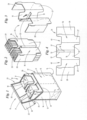
- each pack 10 is a collar 26 in a different configuration.
- the basic components of the collar 26, however, are always a collar front wall 27, which rests against the front wall 15 of the box part 11 and is optionally bonded thereto by adhesive.
- the collar 26 includes collar side walls 28, which extend along side walls 16, 17 of the box part 11. An upper region of the collar 26 protruding from the box part 11 is enclosed by the lid 13 when the pack 10 is in the closed position.
- the cuboid pack 10 thus formed from thin cardboard is particularly suitable for holding cigarettes or other rod-shaped objects.
- the cigarettes are formed as a cigarette group 29 and are surrounded by an inner blank 30, for example made of tin foil. This creates a cigarette block 31.
- the cigarette group 29 or the cigarette block 31 is essentially cuboid-shaped, with a square or rectangular cross-section. It is understood that the cigarette group 29 or the cigarette block 31 can also have other cross-sectional shapes, for example, with a trapezoidal or triangular cross-section.
- the dimensions do not correspond, at least in part, to the corresponding dimensions of the interior of the box part 11 or the pack 10, so that without countermeasures, a cavity would arise, or the cigarette group 29 or the cigarette block 31 would not be held securely or properly in the box part 11. Accordingly, at least one dimension of the cigarette group 29 or the cigarette block 31 is smaller than a corresponding dimension of the interior of the box part 11 or the pack 10.
- the invention relates to deviations in the dimensions that arise because one or more cigarette groups 29 or cigarette blocks 31 are accommodated within the pack 10, which, due to the number and/or dimensions of the cigarettes, have a smaller pack content than is usual for such packs 10, so that significant differences in the dimensions exist that must be compensated for in a suitable manner in order to securely accommodate the cigarette group 29 or the cigarette block 31 in the pack 10 despite the different dimensions.
- the cigarette groups 29 or cigarette blocks 31 are essentially square in cross-section, with four cigarettes arranged in four rows. Both cigarette groups 29 or cigarette blocks 31 have identical dimensions. It is understood that the cigarette groups 29 or cigarette blocks 31 may also have different dimensions in a variant.
- a specially designed collar 26 is used, which is formed from several sections or folding tabs.
- Each of the two cigarette groups 29 or cigarette blocks 31 is enclosed by the collar 26 on three sides, namely in the area of the front wall 15 by a collar front wall 27 and in the area of the side walls 16, 17 by outer collar side walls 28.
- inner collar side walls 32 are provided, which extend along mutually facing side surfaces of the spaced-apart cigarette groups 29 or cigarette blocks 31.
- a support member 33 is arranged, which is formed from a folding tab of the collar 26.
- the two inner collar side walls 32 are connected by a connecting strap 34.
- An outer collar side wall 28, a collar front wall 27, and an inner collar side wall 32 each form a section 35, 36 of the collar.
- the two sections are connected to each other by the connecting tab 34.
- the width of the connecting plate 34 corresponds to the width of the support member 33, which is formed by punch cuts 37 from the material of the collar 26 and a fold line 38 is pivotally connected to an upper end of the connecting tab 34.
- the two cigarette groups 29 or cigarette blocks 31 are each wrapped in a section 35, 36 of the collar 26 and the support member 33 is pivoted transversely to the plane of the connecting tab 34 ( Fig. 3 ). In this position, the inner collar side walls 28 rest against the free longitudinal edges of the support member 33 and bridge the distance between the two cigarette groups 29 or cigarette blocks 31, so that the smaller common width of the cigarette groups 29 or cigarette blocks 31 is compensated by the support member 33 of the collar 26.
- a further special feature is that the support member 33 is arranged in such a way that the consumer cannot see into the distance or space between the two cigarette groups 29 or cigarette blocks 31 when the pack is opened.
- the support member 33 is arranged approximately at the level of a closing edge 39 of the box part 11 and runs essentially horizontally or parallel to the bottom wall 14.
- the length of the support member 33 corresponds to the corresponding dimension of the collar side walls or the corresponding depth of the interior of the box part 11, so that the hollow space extending in the box part 11 between the two cigarette groups 29 or cigarette blocks 31 is covered on the top.
- Another special feature concerns the arrangement of otherwise conventional recesses 40 in the area of an upper side of the collar 26 for removing cigarettes. These recesses 40 each extend across the corner in the area of the collar front walls 27 and the adjacent inner collar side walls 32.
- the embodiment of the invention according to Fig. 5 to 8 differs from the first embodiment according to Fig. 1 to 4 on the one hand by the number and size of the cigarette groups 29 and on the other hand by the construction of the collar 26. Accordingly, only the aspects which have been changed so far are described below, whereby the same reference numerals are used for identical parts.
- the pack contents are a single cigarette group 29 or a single cigarette block 31.
- the cigarette group 29 or the cigarette block 31 is arranged centrally or centrally in the box part 11, wherein the width of the cigarette group 29 or the cigarette block 31 is (significantly) smaller than the corresponding dimension of the interior of the box part 11.
- the cigarette group 29 or cigarette block 31 has a rectangular cross-section, with five cigarettes in four rows. It is understood that other cross-sections or a different number of cigarettes are also conceivable.
- the collar 26 is designed as a single piece with a collar front wall 27 having a central recess 40, as well as two collar side walls 28 arranged adjacent to the side walls 16, 17 of the box part 11. There are no special features regarding the depth and height of the cigarette group 29 or the cigarette block 31.
- the support tabs 41 run parallel to the collar side walls 28 and rest against the corresponding side surfaces of the cigarette group 29 or the cigarette block 31 to hold them laterally.
- Another support tab 42 runs transversely to the support tab 41 and extends along the rear wall 12 of the box part 11.
- the two support tabs 41, 42 are formed from the material of the collar by a horizontal punch cut 37 and are connected via fold lines 38 to the collar front wall and via a residual connection 43 to a corner area of the collar side walls 28.
- a cigarette group 29 or a cigarette block 31 is provided, which does not extend over the full depth of the interior of the box part 11. There are no special features regarding the dimensions in width and height.
- the cigarette group 29 or cigarette block 31 has a rectangular cross-section, with ten cigarettes arranged in two rows. It is understood that other cross-sections or a different number of cigarettes are also conceivable.
- the width of the collar side walls 28 is adapted to the depth of the cigarette group 29 or the cigarette block 31.
- the cigarette group 29 or the cigarette block 31 rests against the collar 26 on three sides, namely in the area of the collar front wall 27 and the two collar side walls 28.
- the cigarette group 29 or the cigarette block 31 is positioned so that it rests against the rear wall 12 of the box part 11. Accordingly, the collar front wall 27 is positioned at a distance from the front wall 15 of the box part.
- two support tabs 44 are provided, which are formed by punching from the material of the collar 26. After folding the collar side walls 28, the support tabs 44 each extend in the plane of the collar side walls 28 and protrude beyond the collar front wall 27 to the front wall 15 of the box part 11. and thus ensure stabilization of the collar 26 or the cigarette group 29 or the cigarette block 31.
- the width of the inner lid side flaps 24, 25 is adapted to the position of the lid brakes 45.
- the lid brakes 45 are formed, as usual, in the plane of the collar front wall 27, which, however, is located in a different plane than usual due to the distance from the front wall 15 of the box part 11. Accordingly, the lid side flaps 24, 25 are formed with a smaller width transverse to the longitudinal extent of the blank 46 for the pack 10.
- a further special feature is that the cavity in the box part 11 between the collar front wall 27 and the front wall 15 of the box part 11 is covered on the top.
- a cover flap 47 is formed in extension of the front wall 15 of the box part 11, which is folded into the package 10 in order to cover the space between the front wall 15 of the box part 11 and the collar front wall 27.
- a recess 48 is also formed in the collar front wall 27, in which the cover flap engages with a retaining lug 49.
- a cigarette group 29 or a cigarette block 31 is provided, which has a smaller width than the interior of the box part 11.
- the depth and height of the cigarette group 29 or the cigarette block 31 have no special features.
- the cigarette group 29 or cigarette block 31 has a rectangular cross-section, with five cigarettes in four rows. It is understood that other cross-sections or a different number of cigarettes are also conceivable.
- the cigarette group 29 or the cigarette block 31 is arranged centrally in the box part 12.
- the cigarette group 29 or the cigarette block 31 rests against the collar front wall 27. Laterally, the cigarette group 29 or the cigarette block 31 is supported by a filler body 50, which is formed by walls of the collar 26 and compensates for the different dimensions.
- the collar 26 has a collar front wall that extends across the entire front of the pack 10. Adjoining these are respective collar side walls 28, which extend adjacent to the side walls 16, 17 of the box part 11. Adjoining these are respective folding tabs 51, which extend along the rear wall 12 of the box part 11. These are then followed by folding tabs 52, which extend parallel to the collar side walls 28, namely starting from the folding tabs 51 in the direction of the collar front wall 27. Finally, the folding tabs 52 are connected to the collar front wall 27 via connecting straps 53, so that cuboidal, hollow filler bodies 50 are formed by the walls of the collar 26.
- the filling bodies 50 support the cigarette group 29 or the cigarette block 31 laterally by means of corresponding dimensions by resting on the side walls 16, 17 of the box part 11 on the one hand and the side surfaces of the cigarette group 29 or the cigarette block 31 on the other hand.
- the procedure is that firstly according to Fig. 19 the folding tabs 51, 52 are folded over with the connecting tab 53, wherein the connecting tabs 53 can be connected to the collar front wall 27, for example, by activating hot-melt glue.
- the collar 26 is then laid flat on a cigarette block 31, and by pivoting the collar side walls 28 around the collar front walls 27, the two filler bodies 50 on either side of the cigarette block 31 are erected.
- a fifth example not belonging to the invention is in Fig. 21 to 24 Similar to the third embodiment according to Fig. 9 to 12 the cigarette group 29 or the cigarette block 31 has a width which approximately corresponds to the width of the box part 11, whereas the depth of the cigarette group 29 or the cigarette block 31 is less than the corresponding dimension of the box part 11.
- a special feature is that the collar 26 is designed in the manner of a sleeve in which the cigarette group 29 or the cigarette block 31 is received.
- the sleeve is essentially formed by parts of the collar front wall 27.
- the collar front wall 27 has an incision 55 which extends across the entire width of the collar front wall 27 and on both sides into the adjacent collar side walls 28.
- Fold lines 56 extend from the two lateral ends of the incision 55 towards the underside of the collar 26.
- a lower section 58 of the collar front wall 27 below the incision 55 can be folded into a position according to Fig. 23 bring.
- the leg 60 After folding a material leg 60 located between the two fold lines 56, 57 around the two fold lines 56, 57, the leg 60 rests on the inside of the collar side walls 28, and the lower section 58 is parallel to the upper section 59 of the collar front wall 27, but at a distance from it.
- the distance between the two planes in which the two sections 58, 59 of the collar front wall 27 are arranged essentially corresponds to the depth of the cigarette group 29 or the cigarette block 31. In this way, the cigarette group 29 or the cigarette block 31 rests on the one hand on the front side against the upper section 59 of the collar front wall 27 and on the other hand at the back to the lower section 58 of the collar front wall 27.
- the upper section 59 of the collar front wall 27 rests on the inside against the front wall 15 of the box part 11.
- the lower section 58 of the collar front wall 27 is spaced from the front wall 15 according to the width of the legs 60.
- the legs 60 are dimensioned such that the lower section 58 is also arranged at a distance from the rear wall 12.
- the width of the legs 60 can be dimensioned such that the lower section 58 is spaced from the upper section 59 according to the dimensions of the cigarette group 29 or the cigarette block 31.
- the upper section 59 could alternatively be arranged at a corresponding distance from the front wall 15 of the box part 11.
- a combination of the two measures is also conceivable.
- a sixth non-inventive example according to Fig. 25 to 28 differs from the fifth embodiment described above only in details in the area of section 58 of the collar 26. In this respect, only the resulting special features will be discussed below. Otherwise, reference is made to the description of the fifth embodiment according to Fig. 21 to 24 referred to.
- the section 58 of the collar 26 has two additional folding lines 61, 62 around which the section 58 can be folded so that the cavity between the back of the cigarette group 29 or the cigarette block 31 and the inside of the rear wall 12 is partially closed.
- the section 58 is folded around the two fold lines 61, 62 into a Z-shaped configuration such that a material strip 63 between the two fold lines 61, 62 corresponds to the width of the cavity and runs parallel to the bottom wall 14, thus concealing a lower part of the cavity.
- a lower material section 64 below the fold line 62 rests against the rear wall 12 and can be connected thereto by adhesive.
- An upper material section 65 of the section 58 rests against the rear side of the cigarette block 31, as in the previous embodiment.
- the fold lines 61, 62 run parallel to each other and to the incision 55.
- the lower fold line 62 continues to run at the level of the underside of the collar side walls 28, so that the material section 64 is formed by a projection which corresponds in size and shape to an opposite recess 65 in the region of an upper side of the collar 26, which serves to facilitate the removal of cigarettes from the pack 10.
- the cigarette group 29 or the cigarette block 31 deviates from the corresponding dimensions of the interior of the box part 11 in only one dimension, namely either the width or the depth.
- the height of the cigarette group 29 or the cigarette block 31 there are no special features in any of the cases.
- the dimensions of the cigarette group 29 or the cigarette block 31 differ in more than one dimension or direction from the corresponding dimensions of the interior of the box part 11. If necessary, several of the individual measures can be combined to compensate for the different dimensions.
- the cigarette groups 29 or cigarette blocks 31 should, if possible, have a greater width than depth in order to be able to properly fold the inner blank in the area of the top side.
- the contents of the pack can generally be cigarettes of normal dimensions, or cigarettes with a smaller diameter than normal cigarettes, namely so-called slim or super-slim cigarettes.
Landscapes
- Engineering & Computer Science (AREA)
- Mechanical Engineering (AREA)
- Packaging Of Annular Or Rod-Shaped Articles, Wearing Apparel, Cassettes, Or The Like (AREA)
Description
- Die Erfindung betrifft eine Packung für Zigaretten gemäß dem Oberbegriff des Anspruchs 1.
- In der Praxis kann es aus verschiedenen Gründen vorkommen, dass die Packungsgrößen bzw. die Abmessungen von Packungen für Zigaretten vorgegeben sind, beispielsweise aus gesetzlichen, steuerlichen oder technischen Gründen. Um eine kostengünstige Herstellung von Packungen zu gewährleisten, ist es aber wünschenswert, dass die Packung bei konstanten (Außen-)Abmessungen mit unterschiedlichen Inhalten befüllt werden können, um flexibel auf entsprechende Vorgaben in verschiedenen Märkten reagieren zu können, ohne dass eine kostspielige Umrüstung der Verpackungsmaschinen erforderlich wäre. Insbesondere ist es von Interesse eine geringere Anzahl von Zigaretten bzw. Zigarettengruppen mit geringeren Abmessungen in üblichen Packungen unterzubringen.
- Aus der
US 5,158,664 ist es bekannt, einen speziellen Kragen einzusetzen, um die Breite des Innenraums des Schachtelteils zu reduzieren. Hierbei weist der Kragen innere und äußere Seitenwände auf. Die inneren Seitenwände sind mit Abstand zu den äußeren Seitenwänden angeordnet, sodass die Breite des Innenraums entsprechend reduziert wird. Die Zigaretten liegen innenseitig an den inneren Seitenwänden an. Ein Nachteil diese Lösung besteht darin, dass der spezielle Kragen aus einem komplizierten Zuschnitt mit vielen Wandungen hergestellt wird, der einer komplexen Handhabung bzw. Faltung bedarf. - Einen anderen Weg geht die
US 4,850,482 , bei der ein Einsatz benutzt wird, der ein rückseitiges Füllstück aufweist. Auch hier ist der Zuschnitt sehr kompliziert aufgebaut. - Vor diesem Hintergrund liegt der Erfindung die Aufgabe zugrunde Packungen für Zigaretten weiterzuentwickeln, insbesondere im Hinblick auf eine möglichst vorteilhafte Aufnahme unterschiedlicher Packungsinhalte in vorzugsweise standardisierten Packungen.
- Eine Packung zur Lösung dieser Aufgabe weist die Merkmale des Anspruchs 1 auf.
- Ein bevorzugtes Ausführungsbeispiel der Erfindung wird nachfolgend anhand der Zeichnung erläutert. In dieser zeigen:
- Fig. 1
- ein nicht zur Erfindung gehöriges erstes Beispiel einer Packung für Zigaretten mit geöffnetem Deckel in räumlicher Darstellung,
- Fig. 2
- den Inhalt der Packung gemäß
Fig. 1 in teilweiser räumlicher Darstellung, - Fig. 3
- einen Kragen für die Packung gemäß
Fig. 1 in teilweise gefalteter Stellung, - Fig. 4
- den Kragen gemäß
Fig. 3 im Grundriss, - Fig. 5
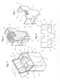
- ein erfindungsgemäßes Ausführungsbeispiel einer Packung für Zigaretten in räumlicher Darstellung,
- Fig. 6
- den Inhalt der Packung gemäß
Fig. 5 in teilweiser räumlicher Darstellung, - Fig. 7
- einen Kragen für die Packung gemäß
Fig. 5 in teilweise gefalteter Stellung, - Fig. 8
- den Kragen gemäß
Fig. 7 im Grundriss, - Fig. 9
- ein nicht zur Erfindung gehöriges Beispiel einer Packung für Zigaretten mit geöffnetem Deckel in räumlicher Darstellung,
- Fig. 10
- den Inhalt der Packung gemäß
Fig. 9 in teilweiser räumlicher Darstellung, - Fig. 11
- einen Kragen für die Packung gemäß
Fig. 9 in teilweise gefalteter Stellung, - Fig. 12
- den Kragen gemäß
Fig. 11 im Grundriss, - Fig. 13
- einen Zuschnitt für die Packung gemäß
Fig. 9 im Grundriss - Fig. 14
- einen Zuschnitt für die Packung gemäß
Fig. 9 im Vertikalschnitt entlang Schnittlinie XIV - XIV, - Fig. 15
- ein nicht zur Erfindung gehöriges Beispiel einer Packung für Zigaretten mit geöffnetem Deckel in räumlicher Darstellung,
- Fig. 16
- den Inhalt der Packung gemäß
Fig. 15 in teilweiser räumlicher Darstellung, - Fig. 17
- einen Kragen für die Packung gemäß
Fig. 15 in teilweise gefalteter Stellung, - Fig. 18
- den Kragen gemäß
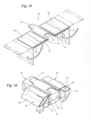
Fig. 15 im Grundriss, - Fig. 19
- eine schematische Darstellung eines ersten Faltschritts für den Kragen der Packung gemäß
Fig. 15 , - Fig. 20
- eine schematische Darstellung eines zweiten Faltschritts für den Kragen der Packung gemäß
Fig. 15 , - Fig. 21
- ein nicht zur Erfindung gehöriges Beispiel einer Packung für Zigaretten mit geöffnetem Deckel in räumlicher Darstellung,
- Fig. 22
- den Inhalt der Packung gemäß
Fig. 21 in teilweise räumlicher Darstellung, - Fig. 23
- einen Kragen für die Packung gemäß
Fig. 21 in gefalteter Stellung, - Fig. 24
- den Kragen für die Packung gemäß
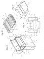
Fig. 21 im Grundriss, - Fig. 25
- ein nicht zur Erfindung gehöriges Beispiel einer Packung für Zigaretten mit geöffnetem Deckel in räumlicher Darstellung,
- Fig. 26
- einen Vertikalschnitt durch die Packung gemäß
Fig. 25 entlang Schnittlinie XXVI - XXVI inFig. 25 , - Fig. 27
- einen Kragen für die Packung gemäß
Fig. 25 in gefalteter Stellung, und - Fig. 28
- den Kragen für die Packung gemäß
Fig. 25 im Grundriss. - Die Erfindung wird nachfolgend an verschiedenen Beispielen beschrieben, die sich jeweils auf eine Packung 10 des Typs Klappschachtel (Hinge-Lid-Packung) für Zigaretten bezieht. Es wird explizit darauf hingewiesen, dass sich die Erfindung auf andere Typen von Packungen für Zigaretten beziehen kann. Nur die im Ausführungsbeispiel gemäß
Fig. 5 bis 8 gezeigte Packung fällt unter die Erfindung. - Die in den Fig. gezeigten Packungen 10 bestehen aus einem Schachtelteil 11 und einem schwenkbar im Bereich einer Rückwand 12 des Schachtelteils 11 angebrachten Deckel 13. Das Schachtelteil 11 besteht ferner aus einer (unteren) Bodenwand 14 und einer (aufrechten) Vorderwand 15, die der Rückwand 12 gegenüber liegt. Seitenwände 16, 17 verbinden Rückwand 12 und Vorderwand 15 miteinander und sind aus einander überdeckenden, inneren und äußeren Seitenlappen 18, 19 gebildet. Der Deckel 13 besteht ebenfalls aus Vorderwand 20, Rückwand 21, Stirnwand 54 und Seitenwänden 22, 23. Die Seitenwände 22, 23 des Deckels 13 sind ebenfalls durch einander überdeckende, innere und äußere Seitenlappen 24, 25 gebildet.
- Ein weiterer Bestandteil der Packungen 10 ist jeweils ein Kragen 26 in unterschiedlicher Konfiguration. Grundbestandteile des Kragens 26 sind aber stets eine Kragen-Vorderwand 27, die an der Vorderwand 15 des Schachtelteils 11 anliegt und gegebenenfalls mit dieser durch Klebung verbunden ist. Weiterhin gehören zum Kragen 26 Kragen-Seitenwände 28, die sich entlang von Seitenwänden 16, 17 des Schachtelteils 11 erstrecken. Ein aus dem Schachtelteil 11 herausragender oberer Bereich des Kragens 26 wird durch den Deckel 13 in Schließstellung der Packung 10 umschlossen.
- Die so ausgebildete, quaderförmige Packung 10 aus dünnem Karton ist besonders geeignet für die Aufnahme von Zigaretten oder anderen stabförmigen Gegenständen. Die Zigaretten werden als Zigarettengruppe 29 formiert und sind durch einen Innenzuschnitt 30 beispielsweise aus Stanniol umgeben. Es entsteht so ein Zigarettenblock 31. In den gezeigten Ausführungsbeispielen ist die Zigarettengruppe 29 bzw. der Zigarettenblock 31 im Wesentlichen quaderförmig ausgebildet, mit einem quadratischen oder rechteckigen Querschnitt. Es versteht sich, dass die Zigarettengruppe 29 bzw. der Zigarettenblock 31 auch andere Querschnittsformen aufweisen kann, beispielsweise mit einem trapezförmigen oder dreieckigen Querschnitt.
- Eine Besonderheit besteht hinsichtlich der Abmessungen der Zigarettengruppe 29 bzw. des Zigarettenblocks 31. Die Abmessungen (Breite, Höhe, Tiefe) entsprechen nämlich zumindest teilweise nicht den entsprechenden Abmessungen des Innenraums des Schachtelteils 11 bzw. der Packung 10, sodass ohne Gegenmaßnahmen ein Hohlraum entstehen würde, bzw. die Zigarettengruppe 29 bzw. der Zigarettenblock 31 nicht sicher bzw. ordnungsgemäß im Schachtelteil 11 gehalten würden. Entsprechend ist mindestens eine Abmessung der Zigarettengruppe 29 bzw. des Zigarettenblocks 31 kleiner als eine entsprechende Abmessung des Innenraums des Schachtelteils 11 bzw. der Packung 10.
- Sofern im Rahmen dieser Anmeldung darauf abgestellt wird, dass die Abmessungen (von Zigarettengruppe 29 bzw. Zigarettenblock 31 einerseits und des Innenraums des Schachtelteils 11 bzw. der Packung 10 andererseits) unterschiedlich sind, so bezieht sich dies nicht auf die üblichen Abweichungen, die im Zuge von Maß- und Fertigungstoleranzen bzw. zwecks einfacher Entnahme der Zigaretten üblicherweise vorhanden sind, sondern um Abweichungen die über dieses Maß hinaus gehen. Die Erfindung bezieht sich auf Abweichungen in den Abmessungen, die dadurch entstehen, dass innerhalb der Packung 10 eine oder mehrere Zigarettengruppen 29 bzw. Zigarettenblöcke 31 Aufnahme finden, die aufgrund der Anzahl und/oder Abmessungen der Zigaretten einen geringeren Packungsinhalt haben als bei derartigen Packungen 10 üblich, sodass signifikante Unterschiede in den Abmessungen bestehen, die auf geeignete Weise ausgeglichen werden müssen, um die Zigarettengruppe 29 bzw. den Zigarettenblock 31 trotz der abweichenden Abmessungen sicher in der Packung 10 aufzunehmen.
- Im ersten nicht zur Erfindung gehörigen Beispiel gemäß
Fig. 1 bis 4 sind zwei Zigarettengruppen 29 bzw. Zigarettenblöcke 31 vorgesehen, deren Breite gemeinsam geringer als die Breite des Innenraums des Schachtelteils 10 ausgebildet ist. Hinsichtlich der Tiefe und der Höhe bestehen keine Besonderheiten bzw. unterschiedliche Abmessungen. - Die Zigarettengruppen 29 bzw. die Zigarettenblöcke 31 sind im Querschnitt im Wesentlichen quadratisch ausgebildet, mit einer Anordnung von jeweils vier Zigaretten in vier Reihen. Beide Zigarettengruppen 29 bzw. Zigarettenblöcke 31 verfügen über identische Abmessungen. Es versteht sich, dass die Zigarettengruppen 29 bzw. Zigarettenblöcke 31 in einer Variante auch unterschiedliche Abmessungen aufweisen können.
- Zum Ausgleich der geringeren Breite der beiden Zigarettengruppen 29 bzw. Zigarettenblöcke 31 kommt ein in besonderer Weise gestalteter Kragen 26 zum Einsatz, der aus mehreren Abschnitten bzw. Faltlappen gebildet ist. Jede der beiden Zigarettengruppen 29 bzw. Zigarettenblöcke 31 wird durch den Kragen 26 an drei Seiten umschlossen, nämlich im Bereich der Vorderwand 15 durch eine Kragen-Vorderwand 27 sowie im Bereich der Seitenwände 16, 17 durch äußere Kragen-Seitenwände 28. Ferner sind innere Kragen-Seitenwände 32 vorgesehen, die sich entlang von einander zugewandten Seitenflächen der im Abstand zueinander angeordneten Zigarettengruppen 29 bzw. Zigarettenblöcke 31 erstrecken. Zwischen den beiden inneren Kragen-Seitenwänden 32 ist ein Stützorgan 33 angeordnet, welches aus einem Faltlappen des Kragens 26 gebildet ist. Ferner sind die beiden inneren Kragen-Seitenwände 32 durch eine Verbindungslasche 34 verbunden.
- Jeweils eine äußere Kragen-Seitenwand 28, eine Kragen-Vorderwand 27 und eine innere Kragen-Seitenwand 32 bilden einen Abschnitt 35, 36 des Kragens. Die beiden Abschnitte werden durch die Verbindungslasche 34 miteinander verbunden.
- Die Breite der Verbindungslasche 34 entspricht der Breite des Stützorgans 33, das durch Stanzschnitte 37 aus dem Material des Kragens 26 gebildet und um eine Faltlinie 38 schwenkbar mit einem oberen Ende der Verbindungslasche 34 schwenkbar verbunden ist.
- Bei der Herstellung der Packung 10 werden die beiden Zigarettengruppen 29 bzw. Zigarettenblöcke 31 in jeweils einen Abschnitt 35, 36 des Kragens 26 eingewickelt und das Stützorgan 33 quer zur Ebene der Verbindungslasche 34 geschwenkt (
Fig. 3 ). In dieser Stellung liegen die inneren Kragen-Seitenwände 28 an den freien Längsrändern des Stützorgans 33 an und überbrücken den Abstand zwischen den beiden Zigarettengruppen 29 bzw. Zigarettenblöcken 31, sodass die kleinere gemeinsame Breite der Zigarettengruppen 29 bzw. Zigarettenblöcke 31 durch das Stützorgan 33 des Kragens 26 ausgeglichen wird. - Eine weitere Besonderheit besteht darin, dass das Stützorgan 33 so angeordnet ist, dass der Konsument bzw. Verbraucher bei geöffneter Packung nicht in den Abstand bzw. Raum zwischen den beiden Zigarettengruppen 29 bzw. Zigarettenblöcken 31 sehen kann.
- Im vorliegenden Fall ist das Stützorgan 33 etwa auf Höhe einer Schließkante 39 des Schachtelteils 11 angeordnet und verläuft im Wesentlichen horizontal bzw. parallel zur Bodenwand 14. Die Länge des Stützorgans 33 entspricht dabei der entsprechenden Abmessung der Kragen-Seitenwände bzw. der entsprechenden Tiefe des Innenraums des Schachtelteils 11, sodass der sich im Schachtelteil 11 erstreckende Hohlraum zwischen den beiden Zigarettengruppen 29 bzw. Zigarettenblöcken 31 oberseitig abgedeckt wird.
- Eine weitere Besonderheit betrifft die Anordnung von ansonsten üblichen Ausnehmungen 40 im Bereich einer Oberseite des Kragens 26 zur Entnahme von Zigaretten. Diese Ausnehmungen 40 erstrecken sich jeweils über Eck im Bereich der Kragen-Vorderwände 27 sowie der daran anschließenden inneren Kragen-Seitenwände 32.
- Das Ausführungsbeispiel der Erfindung gemäß
Fig. 5 bis 8 unterscheidet sich vom ersten Ausführungsbeispiel gemäßFig. 1 bis 4 zum einen durch die Anzahl und Größe der Zigarettengruppen 29 und zum anderen durch die Konstruktion des Kragens 26. Entsprechend werden nachfolgend nur die soweit geänderten Aspekte beschrieben, wobei für übereinstimmende Teile die gleichen Bezugszeichen benutzt werden. - Bei dem Packungsinhalt handelt es sich beim zweiten Ausführungsbeispiel um eine einzelne Zigarettengruppe 29 bzw. um einen einzelnen Zigarettenblock 31. Die Zigarettengruppe 29 bzw. der Zigarettenblock 31 ist zentral bzw. mittig im Schachtelteil 11 angeordnet, wobei die Breite der Zigarettengruppe 29 bzw. des Zigarettenblocks 31 (deutlich) geringer als die entsprechende Abmessung des Innenraums des Schachtelteils 11 ist.
- Die Zigarettengruppe 29 bzw. der Zigarettenblock 31 ist im Querschnitt rechteckig ausgebildet mit jeweils fünf Zigaretten in vier Reihen. Es versteht sich, dass auch andere Querschnitte bzw. eine abweichende Anzahl an Zigaretten denkbar ist.
- Der Kragen 26 ist wie beim ersten Ausführungsbeispiel einteilig ausgestaltet mit einer Kragen-Vorderwand 27, die eine zentrale Ausnehmung 40 aufweist, sowie zwei Kragen-Seitenwänden 28, die benachbart zu den Seitenwänden 16, 17 des Schachtelteils 11 angeordnet sind. Bezüglich der Tiefe und Höhe der Zigarettengruppe 29 bzw. des Zigarettenblocks 31 bestehen keine Besonderheiten.
- Aufgrund der geringeren Breite der Zigarettengruppe 29 bzw. des Zigarettenblocks 31 liegen dessen Seitenflächen nicht an den Kragen-Seitenwänden 28 an, sondern lediglich an der Kragen-Vorderwand 27. Entsprechend müssen Maßnahmen getroffen werden, um die Zigarettengruppe 29 bzw. den Zigarettenblock 31 seitlich zu halten. Hierzu sind spezielle Stützlaschen 41 vorgesehen, die aus entsprechenden Faltlappen des Kragens 26 gefaltet werden.
- Die Stützlaschen 41 verlaufen einerseits parallel zu den Kragen-Seitenwänden 28 und liegen an den entsprechenden Seitenflächen der Zigarettengruppe 29 bzw. des Zigarettenblocks 31 an, um diese seitlich zu halten. Eine weitere Stützlasche 42 verläuft quer zur Stützlasche 41 und erstreckt sich entlang der Rückwand 12 des Schachtelteils 11.
- Die beiden Stützlaschen 41, 42 werden aus dem Material des Kragens durch einen horizontalen Stanzschnitt 37 gebildet und sind über Faltlinien 38 mit der Kragen-Vorderwand sowie über eine Restverbindung 43 mit einem Eckbereich der Kragen-Seitenwände 28 verbunden.
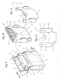
- Im dritten nicht zur Erfindung gehörigen Beispiel gemäß
Fig. 9 bis 14 ist eine Zigarettengruppe 29 bzw. ein Zigarettenblock 31 vorgesehen, der sich nicht über die volle Tiefe des Innenraums des Schachtelteils 11 erstreckt. Hinsichtlich der Abmessungen in der Breite und der Höhe bestehen keine Besonderheiten. - Die Zigarettengruppe 29 bzw. der Zigarettenblock 31 ist im Querschnitt rechteckig ausgebildet, mit jeweils zehn Zigaretten in zwei Reihen. Es versteht sich, dass auch andere Querschnitte bzw. eine abweichende Anzahl an Zigaretten denkbar ist.
- Die Breite der Kragen-Seitenwände 28 ist an die Tiefe der Zigarettengruppe 29 bzw. des Zigarettenblocks 31 angepasst. Die Zigarettengruppe 29 bzw. der Zigarettenblock 31 liegt an drei Seiten am Kragen 26 an, nämlich im Bereich der Kragen-Vorderwand 27 sowie der beiden Kragen-Seitenwände 28.
- Die Zigarettengruppe 29 bzw. der Zigarettenblock 31 ist so positioniert, dass dieser an der Rückwand 12 des Schachtelteils 11 anliegt. Entsprechend ist die Kragen-Vorderwand 27 mit Abstand zur Vorderwand 15 des Schachtelteils positioniert.
- Um diesen Abstand zu überbrücken, sind zwei Stützlaschen 44 vorgesehen, die durch Stanzen aus dem Material des Kragens 26 gebildet sind. Nach dem Umfalten der Kragen-Seitenwände 28 erstrecken sich die Stützlaschen 44 jeweils in der Ebene der Kragen-Seitenwände 28 und ragen über die Kragen-Vorderwand 27 hinaus bis an die Vorderwand 15 des Schachtelteils 11 und sorgen so für eine Stabilisierung des Kragens 26 bzw. der Zigarettengruppe 29 bzw. des Zigarettenblocks 31.
- Eine weitere Besonderheit besteht darin, dass die Breite der inneren Deckel-Seitenlappen 24, 25 an die Position von Deckelbremsen 45 angepasst ist. Die Deckelbremsen 45 sind wie üblich in der Ebene der Kragen-Vorderwand 27 ausgebildet, die sich jedoch wegen des Abstands zur Vorderwand 15 des Schachtelteils 11 in einer anderen Ebene als üblich befindet. Entsprechend sind die Deckel-Seitenlappen 24, 25 mit einer geringeren Breite quer zur Längserstreckung des Zuschnitts 46 für die Packung 10 ausgebildet.
- Eine weitere Besonderheit besteht darin, dass der Hohlraum im Schachtelteil 11 zwischen der Kragen-Vorderwand 27 und der Vorderwand 15 des Schachtelteils 11 oberseitig abgedeckt wird. Hierzu ist etwa auf Höhe der Schließkante 39 des Schachtelteils 11 bzw. geringfügig darunter (
Fig. 14 ) eine Abdecklasche 47 in Verlängerung der Vorderwand 15 des Schachtelteils 11 ausgebildet, die in die Packung 10 hinein gefaltet wird, um den Raum zwischen der Vorderwand 15 des Schachtelteils 11 und der Kragen-Vorderwand 27 abzudecken. - Um die Abdecklasche 47 in der umgefalteten Stellung gemäß
Fig. 14 zu sichern, ist ferner eine Vertiefung 48 in der Kragen-Vorderwand 27 gebildet, in der die Abdecklasche mit einer Haltenase 49 einrastet. - Im vierten nicht zur Erfindung gehörigen Beispiel gemäß
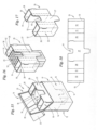
Fig. 15 bis 20 ist wiederum eine Zigarettengruppe 29 bzw. ein Zigarettenblock 31 vorgesehen, der eine geringere Breite als der Innenraum des Schachtelteils 11 aufweist. Die Tiefe und Höhe der Zigarettengruppe 29 bzw. des Zigarettenblocks 31 ist ohne besondere Merkmale. - Die Zigarettengruppe 29 bzw. der Zigarettenblock 31 ist im Querschnitt rechteckig ausgebildet, mit jeweils fünf Zigaretten in vier Reihen. Es versteht sich, dass auch andere Querschnitte bzw. eine abweichende Anzahl an Zigaretten denkbar ist.
- Wie in den beiden vorhergehenden Ausführungsbeispielen ist die Zigarettengruppe 29 bzw. der Zigarettenblock 31 mittig im Schachtelteil 12 angeordnet. Die Zigarettengruppe 29 bzw. der Zigarettenblock 31 liegt an der Kragen-Vorderwand 27 an. Seitlich wird die Zigarettengruppe 29 bzw. der Zigarettenblock 31 durch jeweils einen Füllkörper 50 abgestützt, der durch Wandungen des Kragens 26 gebildet ist und der die unterschiedlichen Abmessungen ausgleicht.
- Der Kragen 26 verfügt über eine Kragen-Vorderwand, die sich über die gesamte Vorderseite der Packung 10 erstreckt. Hieran schließen sich jeweils Kragen-Seitenwände 28 an, die sich benachbart zu den Seitenwänden 16, 17 des Schachtelteils 11 erstrecken. Hieran an schließen sich jeweils Faltlappen 51, die sich entlang der Rückwand 12 des Schachtelteils 11 erstrecken. Es folgen dann wiederum Faltlappen 52, die sich parallel zu den Kragen-Seitenwänden 28 erstrecken, nämlich ausgehend von den Faltlappen 51 in Richtung der Kragen-Vorderwand 27. Schließlich sind die Faltlappen 52 über Verbindungslaschen 53 mit der Kragen-Vorderwand 27 verbunden, sodass quaderförmige, hohle Füllkörper 50 durch die Wandungen des Kragens 26 gebildet werden.
- Die Füllkörper 50 stützen durch entsprechende Abmessungen die Zigarettengruppe 29 bzw. den Zigarettenblock 31 seitlich durch Anlage an den Seitenwänden 16, 17 des Schachtelteils 11 einerseits und den Seitenflächen der Zigarettengruppe 29 bzw. des Zigarettenblocks 31 andererseits.
- Bei der Herstellung der Packung 10 wird so vorgegangen, dass zunächst gemäß
Fig. 19 die Faltlappen 51, 52 mit der Verbindungslasche 53 umgefaltet werden, wobei die Verbindungslaschen 53 beispielsweise durch Aktivieren von Hotmelt-Leim mit der Kragen-Vorderwand 27 verbunden werden können. Danach wird der Kragen 26 flach auf einen Zigarettenblock 31 gelegt und durch Verschwenken der Kragen-Seitenwände 28 um die Kragen-Vorderwände 27 die beiden Füllkörper 50 beiderseits des Zigarettenblocks 31 aufgerichtet. - Ein fünftes nicht zur Erfindung gehöriges Beispiel ist in
Fig. 21 bis 24 gezeigt. Ähnlich wie beim dritten Ausführungsbeispiel gemäßFig. 9 bis 12 verfügt die Zigarettengruppe 29 bzw. der Zigarettenblock 31 über eine Breite, die etwa der Breite des Schachtelteils 11 entspricht, wohingegen die Tiefe der Zigarettengruppe 29 bzw. des Zigarettenblocks 31 jedoch geringer ist als die entsprechende Abmessung des Schachtelteils 11. - Eine Besonderheit besteht darin, dass der Kragen 26 in Art einer Hülse ausgebildet ist, in der die Zigarettengruppe 29 bzw. der Zigarettenblock 31 Aufnahme findet.
- Die Hülse wird im Wesentlichen durch Teile der Kragen-Vorderwand 27 gebildet. Hierzu weist die Kragen-Vorderwand 27 einen Einschnitt 55 auf, der sich über die gesamte Breite der Kragen-Vorderwand 27, sowie beiderseits in die angrenzenden Kragen-Seitenwände 28 erstreckt. Von den beiden seitlichen Enden des Einschnitts 55 in Richtung zur Unterseite des Kragens 26 erstrecken sich jeweils Faltlinien 56. In Verbindung mit den Faltlinien 57 zwischen der Kragen-Vorderwand 27 sowie den beiden angrenzenden Kragen-Seitenwänden 28 lässt sich ein unterer Abschnitt 58 der Kragen-Vorderwand 27 unterhalb des Einschnitts 55 in eine Position gemäß
Fig. 23 bringen. - Nach Faltung eines zwischen den beiden Faltlinien 56, 57 befindlichen Materialschenkels 60 um die beiden Faltlinien 56, 57 liegt der Schenkel 60 jeweils innenseitig an den Kragen-Seitenwänden 28 an und der untere Abschnitt 58 befindet sich parallel zum oberen Abschnitt 59 der Kragen-Vorderwand 27, jedoch mit Abstand zu dieser. Dabei entspricht der Abstand zwischen den beiden Ebenen, in denen die beiden Abschnitte 58, 59 der Kragen-Vorderwand 27 angeordnet sind, im Wesentlichen der Tiefe der Zigarettengruppe 29 bzw. des Zigarettenblocks 31. Auf diese Weise liegt die Zigarettengruppe 29 bzw. der Zigarettenblock 31 einerseits vorderseitig am oberen Abschnitt 59 der Kragen-Vorderwand 27 und andererseits rückseitig am unteren Abschnitt 58 der Kragen-Vorderwand 27 an.
- Wie
Fig. 21 zeigt, liegt der obere Abschnitt 59 der Kragen-Vorderwand 27 innenseitig an der Vorderwand 15 des Schachtelteils 11 an. Der untere Abschnitt 58 der Kragen-Vorderwand 27 ist entsprechend der Breite der Schenkel 60 von der Vorderwand 15 beabstandet. Im vorliegenden Fall sind die Schenkel 60 so bemessen, dass der untere Abschnitt 58 auch mit Abstand zur Rückwand 12 angeordnet ist. Die Breite der Schenkel 60 kann so bemessen werden, dass der untere Abschnitt 58 entsprechend der Abmessung der Zigarettengruppe 29 bzw. des Zigarettenblock 31 vom oberen Abschnitt 59 beabstandet ist. - Grundsätzlich ist es natürlich denkbar, dass alternativ der obere Abschnitt 59 entsprechend mit Abstand zur Vorderwand 15 des Schachtelteils 11 angeordnet wird. Denkbar ist auch eine Kombination der beiden Maßnahmen.
- Ein sechstes nicht zur Erfindung gehöriges Beispiel gemäß
Fig. 25 bis 28 unterscheidet sich von dem vorstehend beschriebenen fünften Ausführungsbeispiel nur durch Details im Bereich des Abschnitts 58 des Kragens 26. Insofern wird nachfolgend auch nur auf die sich hieraus ergebenden Besonderheiten eingegangen. Im Übrigen wird auf die Beschreibung des fünften Ausführungsbeispiels gemäßFig. 21 bis 24 verwiesen. - Wie aus den
Fig. 26 bis 28 ersichtlich, weist der Abschnitt 58 des Kragens 26 zwei zusätzliche Faltlinien 61, 62 auf, um die der Abschnitt 58 gefaltet werden kann, sodass der Hohlraum zwischen der Rückseite der Zigarettengruppe 29 bzw. des Zigarettenblocks 31 und der Innenseite der Rückwand 12 teilweise verschlossen wird. - Vorzugsweise wird der Abschnitt 58 um die beiden Faltlinien 61, 62 in eine Z-förmige Konfiguration gefaltet, derart, dass ein Materialstreifen 63 zwischen den beiden Faltlinien 61, 62 der Breite des Hohlraums entspricht und parallel zur Bodenwand 14 gerichtet verläuft und so einen unteren Teil des Hohlraums verdeckt. Ein unterer Materialabschnitt 64 unterhalb der Faltlinie 62 liegt dabei an der Rückwand 12 an und kann mit dieser durch Klebung verbunden sein. Ein oberer Materialabschnitt 65 des Abschnitts 58 liegt wie im vorherigen Ausführungsbeispiel an der Rückseite des Zigarettenblocks 31 an.
- Im vorliegenden Fall verlaufen die Faltlinien 61, 62 parallel zueinander und zum Einschnitt 55. Die untere Faltlinie 62 verläuft weiterhin auf Höhe der Unterseite der Kragen-Seitenwände 28, sodass der Materialabschnitt 64 durch einen Ansatz gebildet ist, der in Größe und Gestalt einer gegenüberliegenden Ausnehmung 65 im Bereich einer Oberseite des Kragens 26 entspricht, die zur Erleichterung der Entnahme von Zigaretten aus der Packung 10 dient.
- Allen gezeigten Beispielen ist gemeinsam, dass die Zigarettengruppe 29 bzw. der Zigarettenblock 31 jeweils nur in einer Abmessung von den entsprechenden Abmessungen des Innenraums des Schachtelteils 11 abweicht, nämlich entweder in der Breite oder der Tiefe. Hinsichtlich der Höhe der Zigarettengruppe 29 bzw. des Zigarettenblocks 31 sind in keinem der Fälle irgendwelche Besonderheiten gegeben.
- Es kann aber natürlich sein, dass die Abmessungen der Zigarettengruppe 29 bzw. des Zigarettenblocks 31 in mehr als einer Dimension bzw. Richtung von den entsprechenden Abmessungen des Innenraums des Schachtelteils 11 abweichen. Gegebenenfalls können mehrere der einzelnen Maßnahmen zum Ausgleichen der unterschiedlichen Abmessungen miteinander kombiniert werden.
- Weiterhin ist darauf zu achten, dass die Zigarettengruppen 29 bzw. Zigarettenblöcke 31 möglichst eine größere Breite als Tiefe aufweisen sollten, um die Faltung des Innenzuschnitts im Bereich der Oberseite ordnungsgemäß durchführen zu können.
- Beim Packungsinhalt kann es sich grundsätzlich um Zigaretten mit normalen Abmessungen handeln, oder aber auch um Zigaretten mit geringerem Durchmesser als normale Zigaretten, nämlich sogenannte Slim- oder Superslim-Zigaretten.
Claims (2)
- Packung für Zigaretten, mit einem Schachtelteil (11), welches wenigstens durch eine Vorderwand (15), eine Rückwand (12), Seitenwände (16, 17) und eine Bodenwand (14) begrenzt ist, wobei das Schachtelteil (11) zur Aufnahme wenigstens einer in einen Innenzuschnitt (30) eingehüllten vorzugsweise quaderförmigen Zigarettengruppe (29) dient und wobei die Packung (10) vorgegebene Abmessungen hinsichtlich der Breite, der Tiefe und der Höhe aufweist und wenigstens eine Abmessung der wenigstens einen Zigarettengruppe (29) kleiner ist als eine entsprechende Abmessung des Innenraums des Schachtelteils (11), sodass die wenigstens eine Zigarettengruppe (29) den Innenraum des Schachtelteils (11) in Bezug auf die wenigstens eine Abmessung nicht ausfüllt, und wobei im Schachtelteil (11) ein Kragen (26) angeordnet ist, zumindest bestehend aus einer Kragen-Vorderwand (27), die an der Vorderwand (15) des Schachtelteils (11) anliegt und Kragen-Seitenwänden (28), die benachbart zu Seitenwänden (16, 17) des Schachtelteils (11) angeordnet sind, und wobei der Kragen (26) zum Ausgleich wenigstens einer unterschiedlichen Abmessung dient, und wobei die Zigarettengruppe (29) seitlich nicht an den Kragen-Seitenwänden (28) anliegt, sondern beiderseits nur durch Stützlaschen (41) gehalten wird, die durch Falten von Faltlappen des Kragens (26) gebildet werden und die parallel und mit Abstand zur Ebene der Kragen-Seitenwände (28) verlaufen, um wenigstens eine untererschiedliche Abmessung auszugleichen, und dass weitere Stützlaschen (42) quer zu den Stützlaschen (41) verlaufen und sich entlang der Rückwand (12) des Schachtelteils (11) erstrecken, und wobei die Stützlaschen (41, 42) einerseits durch einen Trennschnitt (37) im Material des Kragens (26) abgegrenzt sowie durch Faltlinien (38) mit der Kragen-Vorderwand (27) verbunden sind, dadurch gekennzeichnet, dass die Stützlaschen (42) durch eine Restverbindung (43) mit einer angrenzenden Kragen-Seitenwand (28) verbunden sind.
- Packung nach Anspruch 1, dadurch gekennzeichnet, dass die Stützlaschen (42) über die Restverbindung (43) mit einem Eckbereich der Kragen-Seitenwand (28) verbunden sind.
Priority Applications (1)
| Application Number | Priority Date | Filing Date | Title |
|---|---|---|---|
| PL17000934T PL3243767T3 (pl) | 2014-02-07 | 2015-01-27 | Paczka na papierosy |
Applications Claiming Priority (4)
| Application Number | Priority Date | Filing Date | Title |
|---|---|---|---|
| DE102014101533 | 2014-02-07 | ||
| DE102014108149 | 2014-06-10 | ||
| DE102014014381.3A DE102014014381A1 (de) | 2014-02-07 | 2014-10-02 | Packung für Zigaretten |
| EP15000231.9A EP2905241B1 (de) | 2014-02-07 | 2015-01-27 | Packung für Zigaretten |
Related Parent Applications (2)
| Application Number | Title | Priority Date | Filing Date |
|---|---|---|---|
| EP15000231.9A Division EP2905241B1 (de) | 2014-02-07 | 2015-01-27 | Packung für Zigaretten |
| EP15000231.9A Division-Into EP2905241B1 (de) | 2014-02-07 | 2015-01-27 | Packung für Zigaretten |
Publications (4)
| Publication Number | Publication Date |
|---|---|
| EP3243767A2 EP3243767A2 (de) | 2017-11-15 |
| EP3243767A3 EP3243767A3 (de) | 2017-12-13 |
| EP3243767B1 EP3243767B1 (de) | 2019-03-13 |
| EP3243767B2 true EP3243767B2 (de) | 2025-03-26 |
Family
ID=52423562
Family Applications (2)
| Application Number | Title | Priority Date | Filing Date |
|---|---|---|---|
| EP15000231.9A Active EP2905241B1 (de) | 2014-02-07 | 2015-01-27 | Packung für Zigaretten |
| EP17000934.4A Active EP3243767B2 (de) | 2014-02-07 | 2015-01-27 | Packung für zigaretten |
Family Applications Before (1)
| Application Number | Title | Priority Date | Filing Date |
|---|---|---|---|
| EP15000231.9A Active EP2905241B1 (de) | 2014-02-07 | 2015-01-27 | Packung für Zigaretten |
Country Status (3)
| Country | Link |
|---|---|
| EP (2) | EP2905241B1 (de) |
| DE (1) | DE102014014381A1 (de) |
| PL (2) | PL2905241T3 (de) |
Families Citing this family (16)
| Publication number | Priority date | Publication date | Assignee | Title |
|---|---|---|---|---|
| PL3099586T3 (pl) | 2014-01-31 | 2019-11-29 | Gd Spa | Sztywne opakowanie z uchylnym wieczkieim i zawierające grupę wyrobów do palenia o zmniejszonym wymiarze |
| WO2015124643A1 (en) * | 2014-02-19 | 2015-08-27 | Philip Morris Products S.A. | Container for consumer articles with adjustable inner frame |
| KR20170028959A (ko) * | 2014-07-01 | 2017-03-14 | 지아이엠에이 티티 에스.피.에이. | 흡연 용품용 포장재 |
| KR20170032284A (ko) * | 2014-07-10 | 2017-03-22 | 쥐.디 에스.피.에이. | 담배의 강성 패킷 및 해당 블랭크 |
| GB2530092A (en) * | 2014-09-15 | 2016-03-16 | British American Tobacco Co | Pack For Tobacco Industry Products |
| ITUB20153917A1 (it) * | 2015-09-25 | 2017-03-25 | Gd Spa | Pacchetto di articoli da fumo rigido con coperchio incernierato. |
| ITUB20155348A1 (it) * | 2015-10-28 | 2017-04-28 | Gima Tt S P A | Pacchetto per articoli da fumo |
| ITUB20155933A1 (it) * | 2015-11-26 | 2017-05-26 | Gima Tt S P A | Pacchetto per articoli da fumo |
| IT201700047993A1 (it) * | 2017-05-04 | 2018-11-04 | Gd Spa | Pacchetto di sigarette e metodo per realizzarlo. |
| DE102019108824A1 (de) * | 2019-04-04 | 2020-10-08 | Focke & Co. (Gmbh & Co. Kg) | Packung für Produkte der Tabakindustrie und Verfahren zur Herstellung derselben |
| ES2926174T3 (es) * | 2020-05-12 | 2022-10-24 | Jt Int Sa | Marco interior para un paquete de cigarrillos |
| DE102021104858A1 (de) | 2021-03-01 | 2022-09-01 | Focke & Co. (Gmbh & Co. Kg) | Packung für stabförmige Produkte |
| DE102021118906A1 (de) * | 2021-07-21 | 2023-01-26 | Focke & Co. (Gmbh & Co. Kg) | Packung für Produkte der Zigarettenindustrie |
| WO2023007034A1 (en) * | 2021-07-30 | 2023-02-02 | Philip Morris Products S.A. | Container having inner stiffener |
| DE102021130274A1 (de) * | 2021-11-19 | 2023-05-25 | Focke & Co. (Gmbh & Co. Kg) | Packung für Produkte der Zigarettenindustrie |
| CN114633956A (zh) * | 2022-03-22 | 2022-06-17 | 云南中烟工业有限责任公司 | 一种四盒装卷烟条盒 |
Family Cites Families (10)
| Publication number | Priority date | Publication date | Assignee | Title |
|---|---|---|---|---|
| GB522469A (en) * | 1938-10-12 | 1940-06-19 | John Walker Chalmers | Improvements in or relating to cigarette containers |
| GB585258A (en) | 1945-01-31 | 1947-02-03 | John Walker Chalmers | Improvements in or relating to boxes |
| US4850482A (en) * | 1988-06-10 | 1989-07-25 | Philip Morris Incorporated | Cigarette box innerframe |
| US5158664A (en) | 1991-12-04 | 1992-10-27 | Philip Morris Incorporated | Innerframe for packing cigarettes of variable diameter in standard width pack |
| DE4310769A1 (de) * | 1993-04-02 | 1994-10-06 | Focke & Co | Klappschachtel |
| DE4342523C2 (de) | 1993-12-14 | 2003-03-27 | Focke & Co | Klappschachtel für Zigaretten |
| IT1285635B1 (it) | 1996-03-22 | 1998-06-18 | Gd Spa | Pacchetto rigido con coperchio incernierato per il confezionamento stabile di gruppi di elementi allungati ad ingombro variabile |
| DE102004051981A1 (de) * | 2004-10-25 | 2006-05-04 | Focke & Co.(Gmbh & Co. Kg) | Klappschachtel für Zigaretten |
| ITBO20080411A1 (it) | 2008-06-27 | 2009-12-28 | Gd Spa | Pacchetto per articoli di forma allungata. |
| ITBO20130614A1 (it) | 2013-11-08 | 2015-05-09 | Gima Tt Srl | Confezione rigida con coperchio incernierato |
-
2014
- 2014-10-02 DE DE102014014381.3A patent/DE102014014381A1/de not_active Withdrawn
-
2015
- 2015-01-27 PL PL15000231T patent/PL2905241T3/pl unknown
- 2015-01-27 PL PL17000934T patent/PL3243767T3/pl unknown
- 2015-01-27 EP EP15000231.9A patent/EP2905241B1/de active Active
- 2015-01-27 EP EP17000934.4A patent/EP3243767B2/de active Active
Also Published As
| Publication number | Publication date |
|---|---|
| EP2905241A2 (de) | 2015-08-12 |
| DE102014014381A1 (de) | 2015-08-13 |
| EP3243767A3 (de) | 2017-12-13 |
| PL2905241T3 (pl) | 2017-12-29 |
| PL3243767T3 (pl) | 2019-09-30 |
| EP2905241A3 (de) | 2015-10-14 |
| EP3243767B1 (de) | 2019-03-13 |
| EP3243767A2 (de) | 2017-11-15 |
| EP2905241B1 (de) | 2017-07-12 |
Similar Documents
| Publication | Publication Date | Title |
|---|---|---|
| EP3243767B2 (de) | Packung für zigaretten | |
| EP3194296B1 (de) | Packung für zigaretten | |
| EP0745541B1 (de) | Klappschachtel für Zigaretten | |
| EP0204933B1 (de) | Klappdeckelschachtel für Zigaretten oder dgl. | |
| EP3504133B1 (de) | Packung für zigaretten | |
| EP2977334B1 (de) | Packung für zigaretten und verfahren und vorrichtung zum herstellen derartiger packungen | |
| EP0625469A2 (de) | Verpackung, nämlich Klappschachtel | |
| DE202016000073U1 (de) | Verpackung für Schweissverbrauchsmaterial | |
| EP2905242B1 (de) | Packung für Zigaretten | |
| DE102018005626A1 (de) | Packung für Produkte der Zigarettenindustrie | |
| DE4307386A1 (de) | Verpackung für stabförmige Gegenstände, wie Zigaretten und Verfahren zum Herstellen derselben | |
| EP3853136B1 (de) | Packung für produkte der zigarettenindustrie | |
| DE10226509A1 (de) | Umverpackung | |
| EP1886927A1 (de) | Faltschachtel mit integriertem Füllstück | |
| DE19543719A1 (de) | Verfahren zum Aufrichten und Befüllen einer Faltschachtel und eine solche Faltschachtel | |
| DE19954006A1 (de) | Verpackung, insbesondere aus Wellpappe | |
| WO2006102945A1 (de) | Zigarettenpackung | |
| WO2020200971A1 (de) | Packung für produkte der tabakindustrie und verfahren zur herstellung derselben | |
| DE2140479A1 (de) | Zuschnitt zur herstellung von gefachteilungen | |
| WO2023088744A2 (de) | Packung für produkte der zigarettenindustrie | |
| DE8803238U1 (de) | Verpackung aus zumindest einem Verpackungsunterteil und einem Verpackungsoberteil | |
| DE29901074U1 (de) | Faltschachtel mit Seitenwänden, die durch eine Steckverbindung lösbar miteinander verbunden sind | |
| EP0333911A2 (de) | Behälterverpackung und Zuschnitt hierfür | |
| DE4438628A1 (de) | Packung | |
| DE29724359U1 (de) | Schachtel zur Aufnahme rohrförmiger Elemente |
Legal Events
| Date | Code | Title | Description |
|---|---|---|---|
| PUAI | Public reference made under article 153(3) epc to a published international application that has entered the european phase |
Free format text: ORIGINAL CODE: 0009012 |
|
| STAA | Information on the status of an ep patent application or granted ep patent |
Free format text: STATUS: THE APPLICATION HAS BEEN PUBLISHED |
|
| PUAL | Search report despatched |
Free format text: ORIGINAL CODE: 0009013 |
|
| AC | Divisional application: reference to earlier application |
Ref document number: 2905241 Country of ref document: EP Kind code of ref document: P |
|
| AK | Designated contracting states |
Kind code of ref document: A2 Designated state(s): AL AT BE BG CH CY CZ DE DK EE ES FI FR GB GR HR HU IE IS IT LI LT LU LV MC MK MT NL NO PL PT RO RS SE SI SK SM TR |
|
| AK | Designated contracting states |
Kind code of ref document: A3 Designated state(s): AL AT BE BG CH CY CZ DE DK EE ES FI FR GB GR HR HU IE IS IT LI LT LU LV MC MK MT NL NO PL PT RO RS SE SI SK SM TR |
|
| RIC1 | Information provided on ipc code assigned before grant |
Ipc: B65D 85/10 20060101AFI20171108BHEP |
|
| RIN1 | Information on inventor provided before grant (corrected) |
Inventor name: BUSE, HENRY Inventor name: HEIN, VIKTOR Inventor name: WIXMERTEN, HENNING |
|
| STAA | Information on the status of an ep patent application or granted ep patent |
Free format text: STATUS: REQUEST FOR EXAMINATION WAS MADE |
|
| 17P | Request for examination filed |
Effective date: 20180129 |
|
| RBV | Designated contracting states (corrected) |
Designated state(s): AL AT BE BG CH CY CZ DE DK EE ES FI FR GB GR HR HU IE IS IT LI LT LU LV MC MK MT NL NO PL PT RO RS SE SI SK SM TR |
|
| STAA | Information on the status of an ep patent application or granted ep patent |
Free format text: STATUS: EXAMINATION IS IN PROGRESS |
|
| 17Q | First examination report despatched |
Effective date: 20180329 |
|
| GRAP | Despatch of communication of intention to grant a patent |
Free format text: ORIGINAL CODE: EPIDOSNIGR1 |
|
| STAA | Information on the status of an ep patent application or granted ep patent |
Free format text: STATUS: GRANT OF PATENT IS INTENDED |
|
| INTG | Intention to grant announced |
Effective date: 20180917 |
|
| GRAS | Grant fee paid |
Free format text: ORIGINAL CODE: EPIDOSNIGR3 |
|
| GRAA | (expected) grant |
Free format text: ORIGINAL CODE: 0009210 |
|
| STAA | Information on the status of an ep patent application or granted ep patent |
Free format text: STATUS: THE PATENT HAS BEEN GRANTED |
|
| AC | Divisional application: reference to earlier application |
Ref document number: 2905241 Country of ref document: EP Kind code of ref document: P |
|
| AK | Designated contracting states |
Kind code of ref document: B1 Designated state(s): AL AT BE BG CH CY CZ DE DK EE ES FI FR GB GR HR HU IE IS IT LI LT LU LV MC MK MT NL NO PL PT RO RS SE SI SK SM TR |
|
| REG | Reference to a national code |
Ref country code: GB Ref legal event code: FG4D Free format text: NOT ENGLISH |
|
| REG | Reference to a national code |
Ref country code: CH Ref legal event code: EP Ref country code: AT Ref legal event code: REF Ref document number: 1107402 Country of ref document: AT Kind code of ref document: T Effective date: 20190315 |
|
| REG | Reference to a national code |
Ref country code: IE Ref legal event code: FG4D Free format text: LANGUAGE OF EP DOCUMENT: GERMAN |
|
| REG | Reference to a national code |
Ref country code: DE Ref legal event code: R096 Ref document number: 502015008373 Country of ref document: DE |
|
| REG | Reference to a national code |
Ref country code: NL Ref legal event code: MP Effective date: 20190313 |
|
| REG | Reference to a national code |
Ref country code: LT Ref legal event code: MG4D |
|
| PG25 | Lapsed in a contracting state [announced via postgrant information from national office to epo] |
Ref country code: FI Free format text: LAPSE BECAUSE OF FAILURE TO SUBMIT A TRANSLATION OF THE DESCRIPTION OR TO PAY THE FEE WITHIN THE PRESCRIBED TIME-LIMIT Effective date: 20190313 Ref country code: SE Free format text: LAPSE BECAUSE OF FAILURE TO SUBMIT A TRANSLATION OF THE DESCRIPTION OR TO PAY THE FEE WITHIN THE PRESCRIBED TIME-LIMIT Effective date: 20190313 Ref country code: LT Free format text: LAPSE BECAUSE OF FAILURE TO SUBMIT A TRANSLATION OF THE DESCRIPTION OR TO PAY THE FEE WITHIN THE PRESCRIBED TIME-LIMIT Effective date: 20190313 Ref country code: NO Free format text: LAPSE BECAUSE OF FAILURE TO SUBMIT A TRANSLATION OF THE DESCRIPTION OR TO PAY THE FEE WITHIN THE PRESCRIBED TIME-LIMIT Effective date: 20190613 |
|
| PG25 | Lapsed in a contracting state [announced via postgrant information from national office to epo] |
Ref country code: HR Free format text: LAPSE BECAUSE OF FAILURE TO SUBMIT A TRANSLATION OF THE DESCRIPTION OR TO PAY THE FEE WITHIN THE PRESCRIBED TIME-LIMIT Effective date: 20190313 Ref country code: NL Free format text: LAPSE BECAUSE OF FAILURE TO SUBMIT A TRANSLATION OF THE DESCRIPTION OR TO PAY THE FEE WITHIN THE PRESCRIBED TIME-LIMIT Effective date: 20190313 Ref country code: RS Free format text: LAPSE BECAUSE OF FAILURE TO SUBMIT A TRANSLATION OF THE DESCRIPTION OR TO PAY THE FEE WITHIN THE PRESCRIBED TIME-LIMIT Effective date: 20190313 Ref country code: GR Free format text: LAPSE BECAUSE OF FAILURE TO SUBMIT A TRANSLATION OF THE DESCRIPTION OR TO PAY THE FEE WITHIN THE PRESCRIBED TIME-LIMIT Effective date: 20190614 Ref country code: LV Free format text: LAPSE BECAUSE OF FAILURE TO SUBMIT A TRANSLATION OF THE DESCRIPTION OR TO PAY THE FEE WITHIN THE PRESCRIBED TIME-LIMIT Effective date: 20190313 Ref country code: BG Free format text: LAPSE BECAUSE OF FAILURE TO SUBMIT A TRANSLATION OF THE DESCRIPTION OR TO PAY THE FEE WITHIN THE PRESCRIBED TIME-LIMIT Effective date: 20190613 |
|
| PG25 | Lapsed in a contracting state [announced via postgrant information from national office to epo] |
Ref country code: EE Free format text: LAPSE BECAUSE OF FAILURE TO SUBMIT A TRANSLATION OF THE DESCRIPTION OR TO PAY THE FEE WITHIN THE PRESCRIBED TIME-LIMIT Effective date: 20190313 Ref country code: RO Free format text: LAPSE BECAUSE OF FAILURE TO SUBMIT A TRANSLATION OF THE DESCRIPTION OR TO PAY THE FEE WITHIN THE PRESCRIBED TIME-LIMIT Effective date: 20190313 Ref country code: CZ Free format text: LAPSE BECAUSE OF FAILURE TO SUBMIT A TRANSLATION OF THE DESCRIPTION OR TO PAY THE FEE WITHIN THE PRESCRIBED TIME-LIMIT Effective date: 20190313 Ref country code: ES Free format text: LAPSE BECAUSE OF FAILURE TO SUBMIT A TRANSLATION OF THE DESCRIPTION OR TO PAY THE FEE WITHIN THE PRESCRIBED TIME-LIMIT Effective date: 20190313 Ref country code: AL Free format text: LAPSE BECAUSE OF FAILURE TO SUBMIT A TRANSLATION OF THE DESCRIPTION OR TO PAY THE FEE WITHIN THE PRESCRIBED TIME-LIMIT Effective date: 20190313 Ref country code: PT Free format text: LAPSE BECAUSE OF FAILURE TO SUBMIT A TRANSLATION OF THE DESCRIPTION OR TO PAY THE FEE WITHIN THE PRESCRIBED TIME-LIMIT Effective date: 20190713 Ref country code: SK Free format text: LAPSE BECAUSE OF FAILURE TO SUBMIT A TRANSLATION OF THE DESCRIPTION OR TO PAY THE FEE WITHIN THE PRESCRIBED TIME-LIMIT Effective date: 20190313 |
|
| PG25 | Lapsed in a contracting state [announced via postgrant information from national office to epo] |
Ref country code: SM Free format text: LAPSE BECAUSE OF FAILURE TO SUBMIT A TRANSLATION OF THE DESCRIPTION OR TO PAY THE FEE WITHIN THE PRESCRIBED TIME-LIMIT Effective date: 20190313 |
|
| REG | Reference to a national code |
Ref country code: DE Ref legal event code: R026 Ref document number: 502015008373 Country of ref document: DE |
|
| PLBI | Opposition filed |
Free format text: ORIGINAL CODE: 0009260 |
|
| PG25 | Lapsed in a contracting state [announced via postgrant information from national office to epo] |
Ref country code: IS Free format text: LAPSE BECAUSE OF FAILURE TO SUBMIT A TRANSLATION OF THE DESCRIPTION OR TO PAY THE FEE WITHIN THE PRESCRIBED TIME-LIMIT Effective date: 20190713 |
|
| PLAX | Notice of opposition and request to file observation + time limit sent |
Free format text: ORIGINAL CODE: EPIDOSNOBS2 |
|
| 26 | Opposition filed |
Opponent name: G.D S.P.A. Effective date: 20191209 |
|
| PG25 | Lapsed in a contracting state [announced via postgrant information from national office to epo] |
Ref country code: DK Free format text: LAPSE BECAUSE OF FAILURE TO SUBMIT A TRANSLATION OF THE DESCRIPTION OR TO PAY THE FEE WITHIN THE PRESCRIBED TIME-LIMIT Effective date: 20190313 |
|
| PG25 | Lapsed in a contracting state [announced via postgrant information from national office to epo] |
Ref country code: SI Free format text: LAPSE BECAUSE OF FAILURE TO SUBMIT A TRANSLATION OF THE DESCRIPTION OR TO PAY THE FEE WITHIN THE PRESCRIBED TIME-LIMIT Effective date: 20190313 |
|
| PG25 | Lapsed in a contracting state [announced via postgrant information from national office to epo] |
Ref country code: TR Free format text: LAPSE BECAUSE OF FAILURE TO SUBMIT A TRANSLATION OF THE DESCRIPTION OR TO PAY THE FEE WITHIN THE PRESCRIBED TIME-LIMIT Effective date: 20190313 |
|
| PLBB | Reply of patent proprietor to notice(s) of opposition received |
Free format text: ORIGINAL CODE: EPIDOSNOBS3 |
|
| PG25 | Lapsed in a contracting state [announced via postgrant information from national office to epo] |
Ref country code: MC Free format text: LAPSE BECAUSE OF FAILURE TO SUBMIT A TRANSLATION OF THE DESCRIPTION OR TO PAY THE FEE WITHIN THE PRESCRIBED TIME-LIMIT Effective date: 20190313 |
|
| REG | Reference to a national code |
Ref country code: CH Ref legal event code: PL |
|
| GBPC | Gb: european patent ceased through non-payment of renewal fee |
Effective date: 20200127 |
|
| REG | Reference to a national code |
Ref country code: BE Ref legal event code: MM Effective date: 20200131 |
|
| PG25 | Lapsed in a contracting state [announced via postgrant information from national office to epo] |
Ref country code: LU Free format text: LAPSE BECAUSE OF NON-PAYMENT OF DUE FEES Effective date: 20200127 Ref country code: FR Free format text: LAPSE BECAUSE OF NON-PAYMENT OF DUE FEES Effective date: 20200131 Ref country code: GB Free format text: LAPSE BECAUSE OF NON-PAYMENT OF DUE FEES Effective date: 20200127 |
|
| PG25 | Lapsed in a contracting state [announced via postgrant information from national office to epo] |
Ref country code: BE Free format text: LAPSE BECAUSE OF NON-PAYMENT OF DUE FEES Effective date: 20200131 Ref country code: LI Free format text: LAPSE BECAUSE OF NON-PAYMENT OF DUE FEES Effective date: 20200131 Ref country code: CH Free format text: LAPSE BECAUSE OF NON-PAYMENT OF DUE FEES Effective date: 20200131 |
|
| PG25 | Lapsed in a contracting state [announced via postgrant information from national office to epo] |
Ref country code: IE Free format text: LAPSE BECAUSE OF NON-PAYMENT OF DUE FEES Effective date: 20200127 |
|
| REG | Reference to a national code |
Ref country code: AT Ref legal event code: MM01 Ref document number: 1107402 Country of ref document: AT Kind code of ref document: T Effective date: 20200127 |
|
| PG25 | Lapsed in a contracting state [announced via postgrant information from national office to epo] |
Ref country code: AT Free format text: LAPSE BECAUSE OF NON-PAYMENT OF DUE FEES Effective date: 20200127 |
|
| APAH | Appeal reference modified |
Free format text: ORIGINAL CODE: EPIDOSCREFNO |
|
| APBM | Appeal reference recorded |
Free format text: ORIGINAL CODE: EPIDOSNREFNO |
|
| APBP | Date of receipt of notice of appeal recorded |
Free format text: ORIGINAL CODE: EPIDOSNNOA2O |
|
| PG25 | Lapsed in a contracting state [announced via postgrant information from national office to epo] |
Ref country code: MT Free format text: LAPSE BECAUSE OF FAILURE TO SUBMIT A TRANSLATION OF THE DESCRIPTION OR TO PAY THE FEE WITHIN THE PRESCRIBED TIME-LIMIT Effective date: 20190313 Ref country code: CY Free format text: LAPSE BECAUSE OF FAILURE TO SUBMIT A TRANSLATION OF THE DESCRIPTION OR TO PAY THE FEE WITHIN THE PRESCRIBED TIME-LIMIT Effective date: 20190313 |
|
| PG25 | Lapsed in a contracting state [announced via postgrant information from national office to epo] |
Ref country code: MK Free format text: LAPSE BECAUSE OF FAILURE TO SUBMIT A TRANSLATION OF THE DESCRIPTION OR TO PAY THE FEE WITHIN THE PRESCRIBED TIME-LIMIT Effective date: 20190313 |
|
| APBQ | Date of receipt of statement of grounds of appeal recorded |
Free format text: ORIGINAL CODE: EPIDOSNNOA3O |
|
| P01 | Opt-out of the competence of the unified patent court (upc) registered |
Effective date: 20230517 |
|
| PGFP | Annual fee paid to national office [announced via postgrant information from national office to epo] |
Ref country code: PL Payment date: 20231229 Year of fee payment: 10 |
|
| APBU | Appeal procedure closed |
Free format text: ORIGINAL CODE: EPIDOSNNOA9O |
|
| PGFP | Annual fee paid to national office [announced via postgrant information from national office to epo] |
Ref country code: DE Payment date: 20231228 Year of fee payment: 10 |
|
| PUAH | Patent maintained in amended form |
Free format text: ORIGINAL CODE: 0009272 |
|
| STAA | Information on the status of an ep patent application or granted ep patent |
Free format text: STATUS: PATENT MAINTAINED AS AMENDED |
|
| 27A | Patent maintained in amended form |
Effective date: 20250326 |
|
| AK | Designated contracting states |
Kind code of ref document: B2 Designated state(s): AL AT BE BG CH CY CZ DE DK EE ES FI FR GB GR HR HU IE IS IT LI LT LU LV MC MK MT NL NO PL PT RO RS SE SI SK SM TR |
|
| REG | Reference to a national code |
Ref country code: DE Ref legal event code: R102 Ref document number: 502015008373 Country of ref document: DE |
|
| PGFP | Annual fee paid to national office [announced via postgrant information from national office to epo] |
Ref country code: IT Payment date: 20250131 Year of fee payment: 11 |
|
| REG | Reference to a national code |
Ref country code: DE Ref legal event code: R119 Ref document number: 502015008373 Country of ref document: DE |
|
| PG25 | Lapsed in a contracting state [announced via postgrant information from national office to epo] |
Ref country code: DE Free format text: LAPSE BECAUSE OF NON-PAYMENT OF DUE FEES Effective date: 20250801 |