EP3239576B1 - Haltevorrichtung für ein kabel oder rohr - Google Patents
Haltevorrichtung für ein kabel oder rohr Download PDFInfo
- Publication number
- EP3239576B1 EP3239576B1 EP17152635.3A EP17152635A EP3239576B1 EP 3239576 B1 EP3239576 B1 EP 3239576B1 EP 17152635 A EP17152635 A EP 17152635A EP 3239576 B1 EP3239576 B1 EP 3239576B1
- Authority
- EP
- European Patent Office
- Prior art keywords
- fastening
- holding device
- holding
- bracket
- strap
- Prior art date
- Legal status (The legal status is an assumption and is not a legal conclusion. Google has not performed a legal analysis and makes no representation as to the accuracy of the status listed.)
- Active
Links
- 238000003780 insertion Methods 0.000 claims description 11
- 230000037431 insertion Effects 0.000 claims description 11
- 210000000078 claw Anatomy 0.000 claims description 4
- 238000013461 design Methods 0.000 claims description 3
- 230000003313 weakening effect Effects 0.000 claims 1
- 125000006850 spacer group Chemical group 0.000 description 3
- 239000000758 substrate Substances 0.000 description 3
- 210000003323 beak Anatomy 0.000 description 2
- 239000000463 material Substances 0.000 description 2
- 239000002184 metal Substances 0.000 description 2
- 238000003825 pressing Methods 0.000 description 2
- 210000003813 thumb Anatomy 0.000 description 2
- 238000012549 training Methods 0.000 description 2
- 238000004026 adhesive bonding Methods 0.000 description 1
- 238000013459 approach Methods 0.000 description 1
- 239000011324 bead Substances 0.000 description 1
- 230000015572 biosynthetic process Effects 0.000 description 1
- 239000000919 ceramic Substances 0.000 description 1
- 239000004020 conductor Substances 0.000 description 1
- 230000006378 damage Effects 0.000 description 1
- 230000001419 dependent effect Effects 0.000 description 1
- 239000012777 electrically insulating material Substances 0.000 description 1
- 239000011810 insulating material Substances 0.000 description 1
- 238000000034 method Methods 0.000 description 1
- 239000000843 powder Substances 0.000 description 1
- 230000005855 radiation Effects 0.000 description 1
- 238000011179 visual inspection Methods 0.000 description 1
Images


Classifications
-
- F—MECHANICAL ENGINEERING; LIGHTING; HEATING; WEAPONS; BLASTING
- F16—ENGINEERING ELEMENTS AND UNITS; GENERAL MEASURES FOR PRODUCING AND MAINTAINING EFFECTIVE FUNCTIONING OF MACHINES OR INSTALLATIONS; THERMAL INSULATION IN GENERAL
- F16L—PIPES; JOINTS OR FITTINGS FOR PIPES; SUPPORTS FOR PIPES, CABLES OR PROTECTIVE TUBING; MEANS FOR THERMAL INSULATION IN GENERAL
- F16L3/00—Supports for pipes, cables or protective tubing, e.g. hangers, holders, clamps, cleats, clips, brackets
- F16L3/08—Supports for pipes, cables or protective tubing, e.g. hangers, holders, clamps, cleats, clips, brackets substantially surrounding the pipe, cable or protective tubing
- F16L3/12—Supports for pipes, cables or protective tubing, e.g. hangers, holders, clamps, cleats, clips, brackets substantially surrounding the pipe, cable or protective tubing comprising a member substantially surrounding the pipe, cable or protective tubing
- F16L3/133—Supports for pipes, cables or protective tubing, e.g. hangers, holders, clamps, cleats, clips, brackets substantially surrounding the pipe, cable or protective tubing comprising a member substantially surrounding the pipe, cable or protective tubing and hanging from a pendant
-
- E—FIXED CONSTRUCTIONS
- E21—EARTH OR ROCK DRILLING; MINING
- E21F—SAFETY DEVICES, TRANSPORT, FILLING-UP, RESCUE, VENTILATION, OR DRAINING IN OR OF MINES OR TUNNELS
- E21F17/00—Methods or devices for use in mines or tunnels, not covered elsewhere
- E21F17/02—Suspension devices for tubes or the like, e.g. for ventilating ducts
-
- F—MECHANICAL ENGINEERING; LIGHTING; HEATING; WEAPONS; BLASTING
- F16—ENGINEERING ELEMENTS AND UNITS; GENERAL MEASURES FOR PRODUCING AND MAINTAINING EFFECTIVE FUNCTIONING OF MACHINES OR INSTALLATIONS; THERMAL INSULATION IN GENERAL
- F16L—PIPES; JOINTS OR FITTINGS FOR PIPES; SUPPORTS FOR PIPES, CABLES OR PROTECTIVE TUBING; MEANS FOR THERMAL INSULATION IN GENERAL
- F16L3/00—Supports for pipes, cables or protective tubing, e.g. hangers, holders, clamps, cleats, clips, brackets
- F16L3/08—Supports for pipes, cables or protective tubing, e.g. hangers, holders, clamps, cleats, clips, brackets substantially surrounding the pipe, cable or protective tubing
- F16L3/10—Supports for pipes, cables or protective tubing, e.g. hangers, holders, clamps, cleats, clips, brackets substantially surrounding the pipe, cable or protective tubing divided, i.e. with two or more members engaging the pipe, cable or protective tubing
- F16L3/1075—Supports for pipes, cables or protective tubing, e.g. hangers, holders, clamps, cleats, clips, brackets substantially surrounding the pipe, cable or protective tubing divided, i.e. with two or more members engaging the pipe, cable or protective tubing with two members, the two members being joined with a hinge on one side and fastened together on the other side
-
- F—MECHANICAL ENGINEERING; LIGHTING; HEATING; WEAPONS; BLASTING
- F16—ENGINEERING ELEMENTS AND UNITS; GENERAL MEASURES FOR PRODUCING AND MAINTAINING EFFECTIVE FUNCTIONING OF MACHINES OR INSTALLATIONS; THERMAL INSULATION IN GENERAL
- F16L—PIPES; JOINTS OR FITTINGS FOR PIPES; SUPPORTS FOR PIPES, CABLES OR PROTECTIVE TUBING; MEANS FOR THERMAL INSULATION IN GENERAL
- F16L3/00—Supports for pipes, cables or protective tubing, e.g. hangers, holders, clamps, cleats, clips, brackets
- F16L3/08—Supports for pipes, cables or protective tubing, e.g. hangers, holders, clamps, cleats, clips, brackets substantially surrounding the pipe, cable or protective tubing
- F16L3/12—Supports for pipes, cables or protective tubing, e.g. hangers, holders, clamps, cleats, clips, brackets substantially surrounding the pipe, cable or protective tubing comprising a member substantially surrounding the pipe, cable or protective tubing
- F16L3/127—Supports for pipes, cables or protective tubing, e.g. hangers, holders, clamps, cleats, clips, brackets substantially surrounding the pipe, cable or protective tubing comprising a member substantially surrounding the pipe, cable or protective tubing and extending away from the attachment surface
-
- F—MECHANICAL ENGINEERING; LIGHTING; HEATING; WEAPONS; BLASTING
- F16—ENGINEERING ELEMENTS AND UNITS; GENERAL MEASURES FOR PRODUCING AND MAINTAINING EFFECTIVE FUNCTIONING OF MACHINES OR INSTALLATIONS; THERMAL INSULATION IN GENERAL
- F16L—PIPES; JOINTS OR FITTINGS FOR PIPES; SUPPORTS FOR PIPES, CABLES OR PROTECTIVE TUBING; MEANS FOR THERMAL INSULATION IN GENERAL
- F16L3/00—Supports for pipes, cables or protective tubing, e.g. hangers, holders, clamps, cleats, clips, brackets
- F16L3/08—Supports for pipes, cables or protective tubing, e.g. hangers, holders, clamps, cleats, clips, brackets substantially surrounding the pipe, cable or protective tubing
- F16L3/12—Supports for pipes, cables or protective tubing, e.g. hangers, holders, clamps, cleats, clips, brackets substantially surrounding the pipe, cable or protective tubing comprising a member substantially surrounding the pipe, cable or protective tubing
- F16L3/137—Supports for pipes, cables or protective tubing, e.g. hangers, holders, clamps, cleats, clips, brackets substantially surrounding the pipe, cable or protective tubing comprising a member substantially surrounding the pipe, cable or protective tubing and consisting of a flexible band
-
- H—ELECTRICITY
- H02—GENERATION; CONVERSION OR DISTRIBUTION OF ELECTRIC POWER
- H02G—INSTALLATION OF ELECTRIC CABLES OR LINES, OR OF COMBINED OPTICAL AND ELECTRIC CABLES OR LINES
- H02G3/00—Installations of electric cables or lines or protective tubing therefor in or on buildings, equivalent structures or vehicles
- H02G3/30—Installations of cables or lines on walls, floors or ceilings
- H02G3/32—Installations of cables or lines on walls, floors or ceilings using mounting clamps
-
- H—ELECTRICITY
- H01—ELECTRIC ELEMENTS
- H01Q—ANTENNAS, i.e. RADIO AERIALS
- H01Q1/00—Details of, or arrangements associated with, antennas
- H01Q1/12—Supports; Mounting means
- H01Q1/1207—Supports; Mounting means for fastening a rigid aerial element
- H01Q1/1221—Supports; Mounting means for fastening a rigid aerial element onto a wall
-
- H—ELECTRICITY
- H01—ELECTRIC ELEMENTS
- H01Q—ANTENNAS, i.e. RADIO AERIALS
- H01Q13/00—Waveguide horns or mouths; Slot antennas; Leaky-waveguide antennas; Equivalent structures causing radiation along the transmission path of a guided wave
- H01Q13/20—Non-resonant leaky-waveguide or transmission-line antennas; Equivalent structures causing radiation along the transmission path of a guided wave
- H01Q13/203—Leaky coaxial lines
Definitions
- the invention relates to a holding device for a cable or pipe having the features of the preamble of claim 1.
- the fastening device for the cable or pipe is designed as a clamp and arranged centrally on the holding foot. This complicates the accessibility of the support foot and thus the mounting of the support foot on the ground.
- a stand arranged on the support foot which spaces the fastening device for fastening the cable or pipe from the holding foot at a correct distance, so that the distance does not have to be selected by the installer.
- the fastening device for the cable or pipe has a stand arranged on the hook to which the cable or pipe by means of a fastening tape (like a cable tie) is fixed using a suitable tool. Because the fastening device covers the retaining foot, the hook has a passage opening, which allows the passage of a tool for tightening a fastening means connecting the retaining foot to the ground.
- a holding device which has a stand arranged on the lateral edge region of the holding foot, which allows at least partially accessibility to a holding foot.
- the EP 1 180 838 A1 also shows a holding device which has a stand formed as in the above document.
- the object of the invention is to provide a generic holding device in which the problems discussed above are avoided.
- the stand is arranged on a lateral edge region of the holding foot, so that the side remote from the mounting side of the holding foot next to the stand in a direction normal to the side facing away from the mounting side is at least partially accessible.
- the accessibility is to be provided at least in that area of the side facing away from the mounting side, via which the mounting of the holding device is to take place on a substrate.
- at least one attachment opening can be provided for the passage of a fastening means to be anchored in the ground through the retaining foot. Alternatively, it can be provided to pierce the holding foot with the fastening means during assembly.
- the stand does not have to have a passage opening which allows the passage of a setting tool for setting a fastening means connecting the support foot to the ground, which improves the stability of the stand.
- the holding device apart from the possibly present non-combustible security band and fastening means - integrally formed.
- the holding device apart from the possibly present non-combustible safety band and fastening means - made of an electrically insulating material.
- the holding device apart from the possibly present non-combustible safety band and fastening means - from a (preferably electrically insulating) plastic.
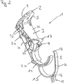
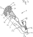
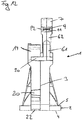
- Fig. 1 shows a first not falling under claim 1 embodiment of a holding device 1 for a cable or pipe, preferably for a so-called beam cable (beam cables are leaky electrical conductors, which are used as elongated antennas).
- beam cables are leaky electrical conductors, which are used as elongated antennas.
- the holding device 1 has a holding foot 2 for mounting the holding device 1 on a substrate (eg cable route, ceiling or wall of a structure - preferably a tunnel or shaft, etc.).
- the assembly takes place with the mounting side 4 of the support foot 2, z.
- a fastening means 28 in the first and / or second attachment opening 12, 13, a fastening means 28 (see. Fig. 6 ) and connected to the ground.
- fasteners 28 are screws, dowels (especially metal dowels), nails.
- fastening device for fastening the cable or pipe to the support foot 2, wherein the fastening device is arranged on a side facing away from the mounting side 4 side 5 of the support foot 2.
- the fastening device has a stand 3 connected to the retaining foot 2, which is arranged on a lateral edge region of the retaining foot 2, so that the side 5 facing away from the mounting side 4 is at least partially accessible in a direction normal to the side 5.
- the selected fastening means 28 can be used without further measures (in particular without the use of adapters) directly in the first and / or second attachment opening 12, 13 and with a suitable setting tool (eg , Screwdrivers, air or powder tools) can be connected to the ground.
- the setting tool has 3 places next to the stand.
- the stand 3 defines a fixed distance from the fastening device for the cable or pipe to the mounting foot 2.
- the distance of the cable or pipe to the ground by the use of spacers, which are arranged between mounting base 2 and ground (preferably with the mounting side 4 of Montagefußes 2 connected) can be increased.
- the mounting foot 2 can have at least one receptacle 21 for at least one positioning pin arranged on the spacer.
- the stand 3 may be formed in the manner of a truss. So you can achieve a sufficient rigidity to the carrying capacity of the holding device 1 with low material usage.
- the upright 3 can be made elastic enough to be able to deform elastically over its entire length, for example in the event of pressure surges (these can arise, for example, due to a train passing through a tunnel) and then return to the starting position.
- the holding foot 2 and the retaining foot 2 connecting to the ground fastener 28 can be largely protected from dynamic forces.
- the framework forms a spring-damper system.
- the stand 3 has two longitudinal struts 31, 32 which connect the mounting foot 2 with the fastening device. Between these longitudinal struts 31, 32 extend a plurality of transverse struts 33rd
- a further advantage of the accessibility of the side 5 of the holding base 2 facing away from the mounting side 4 is the possibility of checking the secure mounting (eg visual inspection, control by means of a torque wrench etc.) and the possibility of any necessary rectification of the assembly.
- the easy accessibility of the side 5 of the support foot 2 also offers advantages for a possibly required disassembly of the cable or pipe from the ground, without the need to solve the cable or pipe from the fastening device for fixing the cable or pipe on the support 2.
- the cable or pipe can be pre-positioned by means of the prefix 14 on the holding device 1.
- the cable or pipe is inserted into the hook-shaped prefix 14 here and can then be aligned axially and / or radially.
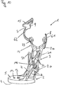
- the prefix 14 according to the invention as in Fig. 9 shown formed in the form of spring clips. In the execution of Fig. 9 The cable or pipe can be pinched between the spring clips and pre-positioned.
- the attachment of the cable or pipe on the support foot 2 can be done by means of the fastening device.
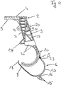
- the fastening band 6 in this exemplary embodiment has a bow-shaped section 10 protruding from the retaining base 2 (cf. Fig. 4 ).
- the free end of the tape 8 can be introduced by applying pressure to the bow-shaped portion 10 of the fastening tape 6 in the opening 9 of the tape fastener 7 and by the tape fastener 7 (this can, for example, in the form of a arranged at least at the free end of the tape 8 teeth, which with a be arranged in the opening 9 arranged locking lug cooperates) are locked.
- an insertion aid is provided in this embodiment.
- the Pressure exercise can z. B. without tools by attaching a hand done.
- a tensioning aid 15 is provided, which provides a defined point of attack. This can be done either manually (eg by means of a thumb) or via a tool (eg with a defined torque).
- Recognizable recess 16 serves to attack a fork-shaped tool.
- At least one joint 23 (designed here as a film joint) is provided, which forms a pivot axis S for a pivoting movement of the bow-shaped section 10 of the fastening strip 6.
- the joint 23 is arranged between a portion of the fastening device arranged on the upright 3 and the fastening band 6.
- the joint 23 could be in another form, for. B. as Achszapfgelenk be formed. It is not necessarily a joint 23 required.
- the fastening band 6 could perform a defined movement.
- the fastening band 6 could have on its side facing the support leg 2 a multiplicity of side-by-side webs. The webs approach each other under pressure up to the plant to each other.
- the fastening band 6 may have wings 26 for the compensation of different diameters of the cables or tubes (cf. Fig. 6b ).
- the device for attaching the securing tape 11 is provided in addition to the fastening device for the cable or pipe.
- the non-flammable security tape 11 forms a fall protection for the cable or pipe in case of fire, which prevents a crash of the cable or pipe even with destruction of the retaining foot 2, the stator 3 and the fastening device.
- the device for attaching the security tape 11 allows a defined course of the security tape 11 along the holding device 1 and thus facilitates a -vorzugêt tool-free - attachment of the security tape 11 to itself.
- the device for attaching the securing tape 11 comprises two retaining clips 20 (possibly only one retaining clip 20 or more than two retaining clips 20 may be provided) and arranged on the mounting side 4 of the retaining foot 2 recess 22 (this is not essential ). Furthermore, one is especially in Fig.2 recognizable guide 19 provided for the backup tape 11.
- the securing tape 11 is inserted into the recess 22 and the retaining clips 20.
- the securing band 11 is already correctly aligned and held relative to the holding device 1.
- the securing band 11 is guided around the cable or pipe, passed through the guide 19 and exits at the other side of the stator 3 via an outlet opening 24 (cf. Fig. 7 ).
- the securing band 11 has a passage opening 25, so that the free end of the securing band 11 can be connected to itself in this area.
- the security tape 11 forms in this state, a loop surrounding the cable or pipe.
- a lateral hooking of the free End of the backup tape 11 on the backup tape 11 done.
- the free end of the securing band 11 in this embodiment, a claw-shaped training. The jaws of the free end can engage behind the securing band 11 in the region of the passage opening 25.
- Another form of connection eg gluing, riveting, etc.
- the passage opening 25 may have a broadening to facilitate the insertion of the claws, wherein the slot is followed by a slit-shaped section. It can be provided that the broadening can be closed by a bendable securing tab 27 when the claw is in the slot-shaped section (cf. Fig. 8 - There, the securing tab 27 is not yet bent).
- the securing band 11 has a prefabricated angled shape (cf. Fig. 8 ).
- openings here on the angled leg
- fastening means 28th There are openings (here on the angled leg) are provided, which are aligned with arranged on the support foot 2 first and second mounting holes 12, 13, for a passage of the fastening means 28th
- sleeves or discs made of an insulating material can be arranged in the region of the openings of the securing band 11 which allow the passage of the fastening means 28. These may be formed integrally with the retaining foot 2. Alternatively, the sleeves or discs can be inserted.
- the non-flammable security tape 11 can - as known per se - z. B. made of metal or ceramic.
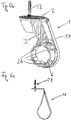
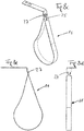
- FIG. 8 An embodiment of a non-flammable security tape 11 is in Fig. 8 shown in different configurations and views.
- Fig. 8a and 8b show a security tape 11, as it is made ready prefabricated to the fitter.
- the Fig. 8c, 8d and 8e show in different views the ready-mounted security tape 11 with hidden holding device. 1
- Fig. 6a shows only the backup tape 11 in this position with hidden holding device.
- Fig. 6b shows the holding device 1 with in the retaining clips 20 (not shown for reasons of clarity) inserted and secured to the support 2 backup tape 11, wherein the backup tape 11 was guided through a guide 19 and attached to itself.
- Fig. 6c shows only the backup tape 11 in this position with hidden holding device. 1
- the backup tape 11 extends with a distance formed by the material of the holding device 1 to the cable or pipe, which is particularly advantageous when using a metallic security tape 11 and the formation of the cable as a beam cable, because so disturbances of the radiation of the beam cable the metallic security tape 11 can be reduced.
- the fastening device for the cable or pipe may have at least one positioning groove 30, for the correct positioning of the cable or pipe on the holding device 1, if the cable or pipe are provided with at least one positioning bead.
- An insertion aid 34 for the securing band 11 can be provided.
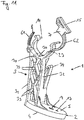
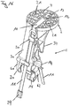
- the fourth embodiment differs from the previous embodiments mainly by the different design of the fastening device for the cable or pipe.
- a strap closure is provided in the fourth embodiment.
- the fastening device has a first bracket 61 and an articulated about a hinge 23 with the support 2 (via the stator 3) second bracket 62.
- the free end of the second bracket 62 carries the opening 9 of the strap closure 7 and is movable by applying pressure to the second bracket 62 via the free end 8 of the first bracket 61 and thus lockable by the strap closure 7.
- the free end 8 of the first bracket 61 is here formed with a taper to facilitate insertion into the opening 9.
- the opening 9 of the strap closure 7 has two insertion bevels 91, 92.
- the pressure can z. B. without tools by attaching a hand done.
- a tensioning aid 15 is provided which a provides defined attack point. This can be done either manually (eg by means of a thumb) or via a tool (eg with a defined torque).
- the joint 23 could be in another form, for. B. as Achszapfgesch be formed.
- the strap closure 7 z. B. be designed so that at the free end 8 of the first bracket 61, a grid is arranged, which cooperates with a arranged in the opening 9 of the swing lock latch.
- at least one hole could be arranged on the first bracket 61, in which a pin arranged in the opening 9 of the clip closure can be pressed.
- the free end 8 of the first bracket 61 is formed without a ratchet, hole or the like and in the opening 9 of the clip closure a limited movable element (eg., Wedge or spherical) is arranged through which after the introduction of the free end 8 of the first bracket 61 into the opening 9, a self-locking locking takes place.
- a limited movable element eg., Wedge or spherical
- the holding device 1 is preferably prefabricated with the securing band 11.
- the backup tape 11 is in the in the Figures 16 and 17 embodiment shown in two parts.
- the first section is arranged in the region of the holding foot 2 and is connected to the second, here V-shaped section, which extends in the region of the stator 3.
- the first section has with the mounting holes 12, 13 of the support foot 2 aligned openings, so that a simultaneous attachment of the non-combustible security tape 11 and the support foot 2 can be done.
- the two free ends of the second section are connected together after the cable or tube has been arranged and would fail in case of failure of the cable U-bolt (eg in case of fire) keep the cable or pipe securely on the ground.
Landscapes
- Engineering & Computer Science (AREA)
- General Engineering & Computer Science (AREA)
- Mechanical Engineering (AREA)
- Mining & Mineral Resources (AREA)
- Architecture (AREA)
- Civil Engineering (AREA)
- Structural Engineering (AREA)
- Life Sciences & Earth Sciences (AREA)
- General Life Sciences & Earth Sciences (AREA)
- Geochemistry & Mineralogy (AREA)
- Geology (AREA)
- Supports For Pipes And Cables (AREA)
Description
- Die Erfindung betrifft eine Haltevorrichtung für ein Kabel oder Rohr mit den Merkmalen des Oberbegriffs des Anspruchs 1.
- Bei bekannten Haltevorrichtungen ist die Befestigungsvorrichtung für das Kabel oder Rohr als Schelle ausgebildet und zentral am Haltefuß angeordnet. Dies erschwert die Zugänglichkeit des Haltefußes und damit die Montage des Haltefußes am Untergrund.
- Bei einer gattungsgemäßen Haltevorrichtung ist ein am Haltefuß angeordneten Ständer vorgesehen, welcher die Befestigungsvorrichtung zur Befestigung des Kabels oder Rohres vom Haltefuß mit einem korrekten Abstand beabstandet, sodass der Abstand nicht vom Monteur gewählt werden muss. Es sind gattungsgemäße Haltevorrichtungen bekannt, bei welchen die Befestigungsvorrichtung für das Kabel oder Rohr einen am Ständer angeordneter Haken aufweist, an welchem das Kabel oder Rohr mittels eines Befestigungsbands (nach Art eines Kabelbinders) unter Einsatz eines geeigneten Werkzeugs befestigt wird. Weil die Befestigungsvorrichtung den Haltefuß verdeckt, weist der Haken eine Durchtrittsöffnung auf, die den Durchtritt eines Werkzeugs zum Festziehen eines den Haltefuß mit dem Untergrund verbindenden Befestigungsmittels gestattet. Bei in die Durchtrittsöffnung eingeführtem Setzwerkzeug ist keine Sicht normal auf den Haltefuß möglich, was eine Kontrolle erschwert. Außerdem muss das Setzwerkzeug nach dem Einfädeln in die Durchtrittsöffnung korrekt ausgerichtet werden um das Befestigungsmittel zu kontaktieren, was ohne direkte Sicht nur unter Mühen möglich ist.
- Aus der
CN 204 254 053 U ist eine Haltevorrichtung bekannt, welche einen am seitlichen Randbereich des Haltefußes angeordneten Ständer aufweist, der eine zumindest teilweise Zugänglichkeit zu einem Haltefuß ermöglicht. - Die
EP 1 180 838 A1 zeigt ebenfalls eine Haltevorrichtung, welche einen wie in obiger Schrift ausgebildeten Ständer aufweist. - Auch aus der zwischen Prioritäts- und Anmeldedatum veröffentlichten
WO 2016/096149 A2 geht eine Haltevorrichtung mit einem solchen Ständer hervor. - Aufgabe der Erfindung ist die Bereitstellung einer gattungsgemäßen Haltevorrichtung bei welcher die oben diskutierten Probleme vermieden werden.
- Diese Aufgabe wird durch eine Haltevorrichtung mit den Merkmalen des Anspruchs 1 gelöst. Vorteilhafte Ausführungsformen der Erfindung sind in den abhängigen Ansprüchen definiert.
- Der Ständer ist an einem seitlichen Randbereich des Haltefußes angeordnet, so dass die von der Montageseite abgewandte Seite des Haltefußes neben dem Ständer in einer Richtung normal auf die von der Montageseite abgewandte Seite wenigstens teilweise zugänglich ist. Die Zugänglichkeit ist wenigstens in jenem Bereich der von der Montageseite abgewandte Seite vorzusehen, über welchen die Montage der Haltevorrichtung an einem Untergrund erfolgen soll. In diesem Bereich kann wenigstens eine Befestigungsöffnung für den Durchtritt eines im Untergrund zu verankerndem Befestigungsmittels durch den Haltefuß vorgesehen sein. Alternativ kann vorgesehen sein, den Haltefuß mit dem Befestigungsmittel bei der Montage zu durchstoßen. Anders als beim Stand der Technik muss der Ständer keine Durchtrittsöffnung aufweisen, die den Durchtritt eines Setzwerkzeugs zum Setzen eines den Haltefuß mit dem Untergrund verbindenden Befestigungsmittels gestattet, was die Stabilität des Ständers verbessert.
- Vorzugsweise ist die Haltevorrichtung - abgesehen vom ggf. vorhandenen nicht-brennbaren Sicherheitsband und Befestigungsmitteln - einstückig ausgebildet.
- Vorzugsweise besteht die Haltevorrichtung - abgesehen vom ggf. vorhandenen nicht-brennbaren Sicherheitsband und Befestigungsmitteln - aus einem elektrisch isolierendem Material.
- Vorzugsweise besteht die Haltevorrichtung - abgesehen vom ggf. vorhandenen nicht-brennbaren Sicherheitsband und Befestigungsmitteln - aus einem (vorzugsweise elektrisch isolierendem) Kunststoff.
- Die Haltevorrichtung ist bevorzugt mit dem Sicherungsband vorkonfektioniert. Ausführungsbeispiele der Erfindung werden anhand der Figuren diskutiert. Es zeigen:
- Fig. 1
- eine isometrische Ansicht eines ersten nicht unter Anspruch 1 fallenden Ausführungsbeispiels
- Fig. 2
- eine weitere isometrische Ansicht zur
Fig. 1 - Fig. 3
- eine weitere isometrische Ansicht zur
Fig. 1 - Fig. 4
- eine Seitenansicht zur
Fig. 1 - Fig. 5
- eine Ansicht zur
Fig. 1 in einer Richtung normal auf die von der Montageseite abgewandte Seite des Montagefußes - Fig. 6a-c
- verschiedene Ansichten zu einem zweiten nicht unter Anspruch 1 fallenden Ausführungsbeispiel
- Fig. 7
- eine weitere isometrische Ansicht zur
Fig. 1 - Fig. 8a-e
- ein Ausführungsbeispiel eines nicht-brennbaren Sicherungsbandes
- Fig. 9
- eine isometrische Ansicht eines dritten erfindungsgemäßen Ausführungsbeispiels
- Fig. 10
- eine isometrische Ansicht eines vierten Ausführungsbeispiels
- Fig. 11
- eine weitere isometrische Ansicht zur
Fig. 10 - Fig. 12
- eine Rückansicht zur
Fig. 10 - Fig. 13
- eine Ansicht zur
Fig. 10 in einer Richtung annähernd normal auf die von der Montageseite abgewandte Seite des Montagefußes - Fig. 14
- eine weitere isometrische Ansicht zur
Fig. 10 - Fig. 15
- eine weitere isometrische Ansicht zur
Fig. 10 - Fig. 16
- eine weitere isometrische Ansicht zur
Fig. 10 mit eingesetztem Sicherungsband - Fig. 17
- eine weitere isometrische Ansicht zur
Fig. 16 -
Fig. 1 zeigt ein erstes nicht unter Anspruch 1 fallendes Ausführungsbeispiel einer Haltevorrichtung 1 für ein Kabel oder Rohr, bevorzugt für ein sogenanntes Strahlkabel (Strahlkabel sind elektrische Leckwellenleiter, die als langgestreckte Antennen verwendet werden). - Die Haltevorrichtung 1 weist einen Haltefuß 2 zur Montage der Haltevorrichtung 1 an einem Untergrund (z. B. Kabeltrasse, Decke oder Wand eines Bauwerkes - vorzugsweise eines Tunnels oder Schachts, usw.) auf. Die Montage erfolgt mit der Montageseite 4 des Haltefuß 2, z. B. indem in die erste und/oder zweite Befestigungsöffnung 12, 13 ein Befestigungsmittel 28 (vgl. z. B.
Fig. 6 ) eingesetzt und mit dem Untergrund verbunden wird. Beispiele für Befestigungsmittel 28 sind Schrauben, Dübel (insbesondere Metalldübel), Nägel. - Es ist eine Befestigungsvorrichtung zur Befestigung des Kabels oder Rohres am Haltefuß 2 vorgesehen, wobei die Befestigungsvorrichtung an einer von der Montageseite 4 abgewandten Seite 5 des Haltefußes 2 angeordnet ist.
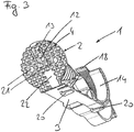
- Die Befestigungsvorrichtung weist einen mit dem Haltefuß 2 verbundenen Ständer 3 auf, welcher an einem seitlichen Randbereich des Haltefußes 2 angeordnet ist, sodass die von der Montageseite 4 abgewandte Seite 5 in einer Richtung normal auf die Seite 5 wenigstens teilweise zugänglich ist. Dies erleichtert die Montage der Haltevorrichtung 1 am Untergrund, das gewählte Befestigungsmittel 28 kann ohne weitere Maßnahmen (insbesondere ohne den Einsatz von Adaptern) direkt in die erste und/oder zweite Befestigungsöffnung 12, 13 eingesetzt und mit einem geeigneten Setzwerkzeug (z. B. Hammer, Schrauber, luft- oder pulvergetriebene Werkzeuge) mit dem Untergrund verbunden werden kann. Das Setzwerkzeug hat neben dem Ständer 3 Platz. Der Ständer 3 definiert einen festen Abstand von der Befestigungsvorrichtung für das Kabel oder Rohr zum Montagefuß 2. Natürlich kann der Abstand des Kabels oder Rohres zum Untergrund durch den Einsatz von Abstandhaltern, die zwischen Montagefuß 2 und Untergrund angeordnet werden (vorzugsweise mit der Montageseite 4 des Montagefußes 2 verbunden) vergrößert werden. Zur korrekten Positionierung solcher Abstandhalter kann der Montagefuß 2 wenigstens eine Aufnahme 21 für wenigstens einen am Abstandhalter angeordneten Positionierzapfen aufweisen.
- Wie in
Fig. 4 gut ersichtlich, kann der Ständer 3 nach Art eines Fachwerkes ausgebildet sein. So erreicht man mit geringem Materialeinsatz eine ausreichende Steifigkeit um die Tragkraft der Haltevorrichtung 1 zu gewährleisten. Der Ständer 3 kann aber elastisch genug ausgebildet sein, um sich beispielsweise bei Druckstößen (diese können z. B. durch einen einen Tunnel durchquerenden Zug entstehen) über seine gesamte Länge elastisch verformen zu können und anschließend wieder in die Ausgangslage zurückkehren zu können. So kann der Haltefuß 2 und ein den Haltefuß 2 mit dem Untergrund verbindendes Befestigungsmittel 28 vor dynamischen Kräften weitgehend geschützt werden. Punktuelle Belastungsspitzen der Haltevorrichtung 1 - vor allem im Bereich der Befestigungsvorrichtung für das Kabel oder Rohr und im Bereich der Befestigungsmittel 28 - wie sie aus dem Stand der Technik bekannt sind, können so vermieden werden, da die dynamischen Kräfte zumindest teilweise bereits im Ständer 3 aufgenommen werden. Das Fachwerk bildet ein Feder-Dämpfer-System. Der Ständer 3 weist zwei Längsstreben 31, 32 auf, die den Montagefuß 2 mit der Befestigungsvorrichtung verbinden. Zwischen diesen Längsstreben 31, 32 verlaufen mehrere Querstreben 33. - Ein weiterer Vorteil der Zugänglichkeit der von der Montageseite 4 abgewandte Seite 5 des Haltefußes 2 ist die Möglichkeit einer Kontrolle der sicheren Montage (z. B. Sichtkontrolle, Kontrolle mittels eines Drehmomentschlüssels usw.) und die Möglichkeit einer allfällig erforderlichen Nachbesserung der Montage. Die leichte Zugänglichkeit der Seite 5 des Haltefußes 2 bietet auch Vorteile für eine möglicherweise erforderliche Demontage des Kabels oder Rohres vom Untergrund, ohne die Notwendigkeit das Kabel oder Rohr von der Befestigungsvorrichtung zur Befestigung des Kabels oder Rohres am Haltefuß 2 lösen zu müssen.
- Ist die Haltevorrichtung 1 am Untergrund montiert, kann das Kabel oder Rohr mittels der Vorfixierung 14 an der Haltevorrichtung 1 vorpositioniert werden. Das Kabel oder Rohr wird in die hier hakenförmige Vorfixierung 14 eingelegt und kann anschließend axial und/oder radial ausgerichtet werden. Anders als in den
Fig. 1 bis 5 dargestellt ist die Vorfixierung 14 gemäß der Erfindung wie inFig. 9 gezeigt in Form von Federklammern ausgebildet. In der Ausführung derFig. 9 kann das Kabel oder Rohr zwischen zwischen den Federklammern eingeklemmt und so vorpositioniert werden. - Ist das Kabel wie gewünscht ausgerichtet, kann die Befestigung des Kabels oder Rohr am Haltefuß 2 mittels der Befestigungsvorrichtung erfolgen.
- Im gezeigten Ausführungsbeispiel ist dies auf besonders einfache Art und Weise möglich, ggf. sogar werkzeuglos. Zu diesem Zweck weist das Befestigungsband 6 in diesem Ausführungsbeispiel einen bügelförmig ausgebildeten und vom Haltefuß 2 abstehenden Abschnitt 10 auf (vgl. z. B.
Fig. 4 ). Das freie Bandende 8 kann durch Druckausübung auf den bügelförmig ausgebildeten Abschnitt 10 des Befestigungsbandes 6 in die Öffnung 9 des Bandverschlusses 7 eingeführt und durch den Bandverschluss 7 (dieser kann z. B. in Form einer zumindest am freien Bandende 8 angeordneten Verzahnung, welche mit einer in der Öffnung 9 angeordneten Rastnase zusammenwirkt ausgebildet sein) verriegelt werden. Zur Erleichterung des Vorganges ist in diesem Ausführungsbeispiel eine Einführhilfe vorgesehen. Diese weist einen am freien Bandende 8 angeordneten Schnabel 18 auf, der über eine vor der Öffnung 9 angeordnete Rampe 17 in die Öffnung 9 geleitet wird. Die Druckausübung kann z. B. werkzeuglos durch Anlage einer Hand erfolgen. In diesem Ausführungsbeispiel ist eine Spannhilfe 15 vorgesehen, die einen definierten Angriffspunkt zur Verfügung stellt. Dies kann sowohl von Hand (z. B. mittels eines Daumens) oder über ein Werkzeug (z. B. mit einem definierten Drehmoment) erfolgen. Die hier vorgesehene und z. B. inFig. 4 erkennbare Ausnehmung 16 dient zum Angriff eines gabelförmigen Werkzeugs. - Es ist vorteilhaft, wenn zumindest ein Gelenk 23 (hier als Filmgelenk ausgebildet) vorgesehen ist, welches eine Schwenkachse S für eine Schwenkbewegung des bügelförmig ausgebildeten Abschnitts 10 des Befestigungsbandes 6 bildet. Hier ist das Gelenk 23 zwischen einem am Ständer 3 angeordneten Abschnitt der Befestigungsvorrichtung und dem Befestigungsband 6 angeordnet. Natürlich könnte auch mehr als ein Gelenk 23 vorgesehen sein. Das Gelenk 23 könnte in anderer Form, z. B. als Achszapfgelenk, ausgebildet sein. Es ist nicht unbedingt ein Gelenk 23 erforderlich. Z. B. könnte das Befestigungsband 6 aufgrund seiner vorgegebenen Form bei Druckausübung auf den bügelförmig ausgebildeten Abschnitt 10 eine definierte Bewegung ausführen. Zu diesem Zweck könnte das Befestigungsband 6 auf seiner dem Stützfuß 2 zugewandten Seite eine Vielzahl von nebeneinander angeordneten Stegen aufweisen. Die Stege nähern sich unter Druckausübung maximal bis zur Anlage einander an.
- Alternativ zur weiter oben beschriebenen Ausbildung des Bandverschlusses 7 mit einer Verzahnung und einer Rastnase kann z. B. auch eine reibschlüssige Ausbildung des Bandverschlusses 7 vorgesehen sein.
- Das Befestigungsband 6 kann Flügel 26 für den Ausgleich unterschiedlicher Durchmesser der Kabel oder Rohre aufweisen (vgl.
Fig. 6b ). Insbesondere in denFig. 3 ,4 und7 ist eine bei diesem Ausführungsbeispiel vorgesehene Vorrichtung zum Anbringen eines nicht-brennbaren Sicherungsbands 11 an der Haltevorrichtung 1 (vgl.Fig. 6a ,6b ) unabhängig von einer Montage der Haltevorrichtung 1 an einem Untergrund erkennbar. Die Vorrichtung zum Anbringen des Sicherungsbandes 11 ist zusätzlich zur Befestigungsvorrichtung für das Kabel oder Rohr vorgesehen. Das nicht-brennbare Sicherungsband 11 bildet im Brandfall eine Absturzsicherung für das Kabel oder Rohr, welche ein Abstürzen des Kabels oder Rohres auch bei Zerstörung des Haltefußes 2, des Ständers 3 und der Befestigungsvorrichtung verhindert. Die Vorrichtung zum Anbringen des Sicherungsbandes 11 gestattet einen definierten Verlauf des Sicherungsbandes 11 entlang der Haltevorrichtung 1 und erleichtert so eine -vorzugsweise werkzeuglose - Befestigung des Sicherungsbandes 11 an sich selbst. - Im gezeigten Ausführungsbeispiel umfasst die Vorrichtung zum Anbringen des Sicherungsbandes 11 zwei Halteklammern 20 (ggf. könnte auch nur eine Halteklammer 20 oder mehr als zwei Halteklammern 20 vorgesehen sein) und eine an der Montageseite 4 des Haltefußes 2 angeordnete Ausnehmung 22 (diese ist nicht unbedingt erforderlich). Weiters ist eine vor allem in
Fig.2 erkennbare Führung 19 für das Sicherungsband 11 vorgesehen. - Noch vor der Montage der Haltevorrichtung 1 am Untergrund und vor der Vorfixierung des Kabels oder Rohres wird das Sicherungsband 11 in die Ausnehmung 22 und die Halteklammern 20 eingelegt. Das Sicherungsband 11 ist bereits jetzt relativ zur Haltevorrichtung 1 korrekt ausgerichtet und gehalten.
- Dann erfolgt die Montage der Haltevorrichtung 1 am Untergrund. Dann erfolgt die Vorfixierung des Kabels oder Rohres. Anschließend wird das Sicherungsband 11 um das Kabel oder Rohr herum geführt, durch die Führung 19 hindurch geführt und tritt an der anderen Seite des Ständers 3 über eine Austrittsöffnung 24 aus (vgl.
Fig. 7 ). Im Bereich der Austrittsöffnung 24 weist das Sicherungsband 11 eine Durchtrittsöffnung 25 auf, sodass das freie Ende des Sicherungsbandes 11 in diesem Bereich mit sich selbst verbunden werden kann. Das Sicherungsband 11 bildet in diesem Zustand eine das Kabel oder Rohr umgebende Schlaufe. Alternativ könnte ein seitliches Einhaken des freien Endes des Sicherungsbandes 11 am Sicherungsband 11 erfolgen. Für die Verbindung weist das freie Ende des Sicherungsbandes 11 in diesem Ausführungsbeispiel eine klauenförmige Ausbildung auf. Die Klauen des freien Endes können das Sicherungsband 11 im Bereich der Durchtrittsöffnung 25 hintergreifen. Eine andere Ausbildung der Verbindung (z. B. Kleben, Vernieten, usw.) wäre denkbar. - Die Durchtrittsöffnung 25 kann eine Verbreiterung zur Erleichterung des Einführens der Klauen aufweisen, wobei sich an die Verbreiterung ein schlitzförmiger Abschnitt anschließt. Es kann vorgesehen sein, dass die Verbreiterung durch eine umbiegbare Sicherungslasche 27 verschließbar ist, wenn sich die Klaue im schlitzförmigen Abschnitt befindet (vgl.
Fig. 8 - dort ist die Sicherungslasche 27 noch nicht umgebogen). - Im gezeigten Ausführungsbeispiel weist das Sicherungsband 11 eine vorgefertigte abgewinkelte Form auf (vgl.
Fig. 8 ). - Es sind Öffnungen (hier am abgewinkelten Schenkel) vorgesehen, die mit am Haltefuß 2 angeordneten ersten und zweiten Befestigungsöffnungen 12, 13 fluchten, für einen Durchtritt der Befestigungsmittel 28.
- Will man das Sicherungsband 11 von den Befestigungsmitteln 28 galvanisch trennen, können im Bereich der Öffnungen des Sicherungsbandes 11, welche den Durchtritt der Befestigungsmittel 28 gestatten, Hülsen oder Scheiben aus einem isolierenden Material angeordnet sein. Diese können einstückig mit dem Haltefuß 2 ausgebildet sein. Alternativ können die Hülsen oder Scheiben eingelegt werden.
- Das nicht-brennbare Sicherungsband 11 kann - wie an sich bekannt - z. B. aus Metall oder Keramik bestehen.
- Ein Ausführungsbeispiel eines nicht-brennbaren Sicherungsbandes 11 ist in
Fig. 8 in unterschiedlichen Konfigurationen und Ansichten gezeigt. -
Fig. 8a und 8b zeigen ein Sicherungsband 11, wie es dem Monteur vorgefertigt zur Verfügung gestellt wird. DieFig. 8c, 8d und 8e zeigen in verschiedenen Ansichten das fertig montierte Sicherungsband 11 bei ausgeblendeter Haltevorrichtung 1. - Das Ausführungsbeispiel der
Fig. 6 unterscheidet sich von jenem derFig. 1 dadurch, dass - das Befestigungsband 6 Flügel 26 für den Ausgleich unterschiedlicher Durchmesser der Kabel oder Rohre aufweist
- die Vorfixierung 14 polygonal ausgebildet ist
- die Vorrichtung zum Anbringen des nicht-brennbaren Sicherungsbands 11 an der Haltevorrichtung 1 drei Halteklammern 20 aufweist
- das nicht-brennbare Sicherungsband 11 an der von der Montageseite 4 abgewandten Seite 5 des Haltefußes 2 befestigt wird
-
Fig. 6a zeigt nur das Sicherungsband 11 in dieser Stellung bei ausgeblendeter Haltevorrichtung 1.Fig. 6b zeigt die Haltevorrichtung 1 mit in die Halteklammern 20 (aus Gründen der Übersichtlichkeit nicht dargestellt) eingesetztem und am Haltefuß 2 befestigtem Sicherungsband 11, wobei das Sicherungsband 11 durch eine Führung 19 hindurch geführt und an sich selbst befestigt wurde.Fig. 6c zeigt nur das Sicherungsband 11 in dieser Stellung bei ausgeblendeter Haltevorrichtung 1. - Das erfindungsgemäße Ausführungsbeispiel der
Fig. 9 unterscheidet sich von jenem derFig. 1 dadurch, dass - die Vorrichtung zum Anbringen des nicht-brennbaren Sicherungsbands 11 an der Haltevorrichtung 1 nur eine Halteklammer 20 aufweist
- die Vorfixierung 14 in Form von Federklammern ausgebildet ist
- In den gezeigten Ausführungsbeispielen verläuft das Sicherungsband 11 mit einem durch das Material der Haltevorrichtung 1 gebildeten Abstand zum Kabel oder Rohr, was vor allem beim Einsatz eines metallischen Sicherungsbandes 11 und der Ausbildung des Kabels als Strahlkabel vorteilhaft ist, weil so Störungen der Abstrahlung des Strahlkabels durch das metallische Sicherungsband 11 reduziert werden.
- Die Befestigungsvorrichtung für das Kabel oder Rohr kann zumindest eine Positioniernut 30 aufweisen, zur lagerichtigen Positionierung des Kabels oder Rohr an der Haltevorrichtung 1, falls das Kabel oder Rohr mit zumindest einer Positionierwulst versehen sind.
- Es kann eine Einführhilfe 34 für das Sicherungsband 11 vorgesehen sein.
- Das vierte Ausführungsbeispiel (vgl.
Fig 10 bis 17 ) unterscheidet sich von den vorherigen Ausführungsbeispielen vor allem durch die unterschiedliche Ausbildung der Befestigungsvorrichtung für das Kabel oder Rohr. Statt eines Bandverschlusses ist beim vierten Ausführungsbeispiel ein Bügelverschluss vorgesehen. Die Befestigungsvorrichtung weist einen ersten Bügel 61 und einen über ein Gelenk 23 gelenkig mit dem Haltefuß 2 (über den Ständer 3) verbundenen zweiten Bügel 62 auf. Das freie Ende des zweiten Bügels 62 trägt die Öffnung 9 des Bügelverschlusses 7 und ist durch Druckausübung auf den zweiten Bügel 62 über das freie Ende 8 des ersten Bügels 61 bewegbar und so durch den Bügelverschluss 7 verriegelbar. - Das freie Ende 8 des ersten Bügels 61 ist hier mit einer Verjüngung ausgebildet, um das Einführen in die Öffnung 9 zu erleichtern. Zum selben Zweck weist die Öffnung 9 des Bügelverschlusses 7 zwei Einführschrägen 91, 92 auf.
- Die Druckausübung kann z. B. werkzeuglos durch Anlage einer Hand erfolgen. In diesem Ausführungsbeispiel ist eine Spannhilfe 15 vorgesehen, die einen definierten Angriffspunkt zur Verfügung stellt. Dies kann sowohl von Hand (z. B. mittels eines Daumens) oder über ein Werkzeug (z. B. mit einem definierten Drehmoment) erfolgen.
- Natürlich könnte auch mehr als ein Gelenk 23 vorgesehen sein. Das Gelenk 23 könnte in anderer Form, z. B. als Achszapfgelenk, ausgebildet sein.
- Der Bügelverschluss 7 kann z. B. so ausgebildet sein, dass am freien Ende 8 des ersten Bügels 61 eine Rasterung angeordnet ist, die mit einer in der Öffnung 9 des Bügelverschlusses angeordneten Rastnase zusammenwirkt. Alternativ könnte auch zumindest ein Loch am ersten Bügel 61 angeordnet sein, in welches ein in der Öffnung 9 des Bügelverschlusses angeordneter Stift eindrückbar ist. Alternativ könnte auch vorgesehen sein, dass das freie Ende 8 des ersten Bügels 61 ohne Rasterung, Loch oder dgl. ausgebildet ist und in der Öffnung 9 des Bügelverschlusses ein begrenzt bewegbares Element (z. B. keil- oder kugelförmig) angeordnet ist, durch welches nach erfolgtem Einbringen des freien Ende 8 des ersten Bügels 61 in die Öffnung 9 ein selbsthemmendes Feststellen erfolgt.
- Die Haltevorrichtung 1 ist bevorzugt mit dem Sicherungsband 11 vorkonfektioniert.
- Das Sicherungsband 11 ist in dem in den
Figuren 16 und17 gezeigten Ausführungsbeispiel zweiteilig ausgeführt. Der erste Abschnitt wird im Bereich des Haltefußes 2 angeordnet und ist mit dem zweiten, hier V-förmig ausgebildeten Abschnitt verbunden, der im Bereich des Ständers 3 verläuft. Der erste Abschnitt weist mit den Befestigungsöffnungen 12, 13 des Haltefußes 2 fluchtende Öffnungen auf, damit eine gleichzeitige Befestigung des nicht-brennbaren Sicherungsbandes 11 und des Haltefußes 2 erfolgen kann. Die beiden freien Enden des zweiten Abschnitts (von denen ein Ende mit einem Bandverschluss 29 versehen ist) werden nach dem Anordnen des Kabels oder Rohres miteinander verbunden und würden bei einem Versagen des Bügelverschlusses (z. B. im Brandfall) das Kabel oder Rohr sicher am Untergrund halten. -
- 1
- Haltevorrichtung
- 2
- Haltefuß
- 3
- Ständer
- 31, 32
- Längsstreben des Ständers
- 33
- Querstreben des Ständers
- 4
- Montageseite
- 5
- von der Montageseite abgewandte Seite
- 6
- Befestigungsband
- 61
- erster Bügel des Bügelverschlusses
- 62
- zweiter Bügel des Bügelverschlusses
- 7
- Bandverschluss
- 8
- freies Bandende des Befestigungsbands bzw. ersten Bügels
- 9
- Öffnung des Bandverschlusses bzw. Bügelverschlusses
- 91
- Einführschräge der Öffnung des Bügelverschlusses
- 92
- Einführschräge der Öffnung des Bügelverschlusses
- 10
- bügelförmiger Abschnitt des Befestigungsbandes
- 11
- nicht-brennbares Sicherungsband
- 12
- erste Befestigungsöffnung
- 13
- zweite Befestigungsöffnung
- 14
- Vorfixierung
- 15
- Spannhilfe
- 16
- Öffnung der Spannhilfe
- 17
- Rampe der Einführhilfe
- 18
- Schnabel der Einführhilfe
- 19
- Führung für Sicherungsband
- 20
- Halteklammern für Sicherungsband
- 21
- Aufnahme für Positionierzapfen
- 22
- Ausnehmung für Sicherungsband
- 23
- Gelenk
- 24
- Austrittsöffnung
- 25
- Durchtrittsöffnung am Sicherungsband
- 26
- Flügel an Befestigungsband oder ersten und zweiten Bügel
- 27
- Sicherungslasche
- 28
- Befestigungsmittel
- 29
- Bandverschluss des Sicherungsbandes
- 30
- Positioniernut
- 34
- Einführhilfe für Sicherungsband
Claims (15)
- Haltevorrichtung (1) für ein Kabel oder Rohr, mit:- einem Haltefuß (2) zur Montage der Haltevorrichtung (1) an einem Untergrund, wobei der Haltefuß (2) eine dem Untergrund zuzuwendende Montageseite (4) und eine davon abgewandte Seite (5) aufweist,- einer Befestigungsvorrichtung zur Befestigung des Kabels oder Rohres am Haltefuß (2),- einen am Haltefuß (2) angeordneten Ständer (3), welcher die Befestigungsvorrichtung zur Befestigung des Kabels oder Rohres vom Haltefuß (2) in einer Richtung normal auf die von der Montageseite (4) abgewandte Seite (5) beabstandet, wobei der Ständer (3) an einem seitlichen Randbereich des Haltefußes (2) angeordnet ist, so dass die von der Montageseite (4) abgewandte Seite (5) des Haltefußes (2) neben dem Ständer (3) in der Richtung normal auf die von der Montageseite (4) abgewandte Seite (5) auch bei durch die Befestigungsvorrichtung befestigtem Kabel oder Rohr wenigstens teilweise zugänglich ist, dadurch gekennzeichnet, dass eine von der Befestigungsvorrichtung verschiedene Vorfixierung (14) für das Kabel oder Rohr vorgesehen ist, wobei die Vorfixierung (14) in einer Axialrichtung des Kabels oder des Rohres, neben der Befestigungsvorrichtung an der vom Haltefuß (2) abgewandten Seite des Ständers (3) angeordnet ist und wobei die Vorfixierung (14) in Form von Federklammern ausgebildet ist, sodass das Kabel oder Rohr zwischen den Federklammern eingeklemmt und so vorpositioniert werden kann.
- Haltevorrichtung (1) nach Anspruch 1, wobei der Haltefuß (2) plattenförmig ausgebildet ist.
- Haltevorrichtung (1) nach wenigstens einem der vorangehenden Ansprüche, wobei die Befestigungsvorrichtung ein Befestigungsband (6) und einen Bandverschluss (7) aufweist, wobei ein freies Bandende (8) des Befestigungsbandes (6) in eine Öffnung (9) des Bandverschlusses (7) einführbar ist und wobei vorgesehen ist, dass- das Befestigungsband (6) einen bügelförmig ausgebildeten und vom Haltefuß (2) abstehenden Abschnitt (10) aufweist- das freie Bandende (8) durch Druckausübung - vorzugsweise auf den bügelförmig ausgebildeten Abschnitt (10) des Befestigungsbandes (6) - in die Öffnung (9) des Bandverschlusses (7) einführbar und durch den Bandverschluss (7) verriegelbar ist.
- Haltevorrichtung (1) nach Anspruch 1 oder 2, wobei die Befestigungsvorrichtung zur Befestigung des Kabels oder Rohr am Haltefuß (2) einen ersten Bügel (61) und einen zweiten Bügel (62) aufweist, die durch einen Bügelverschluss (7) miteinander verriegelbar sind, wobei ein freies Ende (8) des ersten Bügels (61) in eine Öffnung (9) des Bügelverschlusses (7) einführbar ist und wobei die Befestigungsvorrichtung weiters ein Gelenk (23) aufweist, welches den zweiten Bügel (62) mit dem Haltefuß (2) verbindet oder im zweiten Bügel (62) angeordnet ist, wobei der zweite Bügel (62) die Öffnung (9) des Bügelverschlusses (7) trägt und die Öffnung (9) des Bügelverschlusses (7) durch Druckausübung auf den zweiten Bügel (62) über das freie Ende (8) des ersten Bügels (61) bewegbar und durch den Bügelverschluss (7) verriegelbar ist.
- Haltevorrichtung (1) nach Anspruch 3 oder 4, wobei das Befestigungsband (6) bzw. einer der Bügel (61, 62) Flügel (26) für den Ausgleich unterschiedlicher Durchmesser der Kabel oder Rohre aufweist.
- Haltevorrichtung (1) nach wenigstens einem der beiden vorangehenden Ansprüche, wobei zumindest ein Gelenk (23) vorgesehen ist, welches eine Schwenkachse (S) für eine Schwenkbewegung des bügelförmig ausgebildeten Abschnitts (10) des Befestigungsbandes (6) bildet.
- Haltevorrichtung nach wenigstens einem der vorangehenden Ansprüche, wobei die Haltevorrichtung (1) eine Vorrichtung zum Anbringen eines zusätzlich zur Befestigungsvorrichtung vorgesehenen, nicht-brennbaren Sicherungsbands (11) für das Kabel oder Rohr an der Haltevorrichtung (1) unabhängig von einer Montage der Haltevorrichtung (1) am Untergrund aufweist.
- Haltevorrichtung (1) nach dem vorangehenden Anspruch, wobei das Sicherungsband (11) mit sich selbst verbindbar ist, zur Ausbildung einer Schlaufe um ein durch die Befestigungsvorrichtung mit dem Haltefuß (2) verbundenes Rohr oder Kabel.
- Haltevorrichtung (1) nach dem vorangehenden Anspruch, wobei das Sicherungsband (11) eine Durchtrittsöffnung (25) aufweist, in welche ein freies Ende des Sicherungsbandes (11) einführbar ist, wobei bevorzugt vorgesehen ist, dass das freie Ende des Sicherungsbandes (11) eine klauenförmige Ausbildung aufweist und die Klauen des freien Endes das Sicherungsband (11) im Bereich der Durchtrittsöffnung (25) hintergreifen.
- Haltevorrichtung (1) nach dem vorangehenden Anspruch, wobei die Durchtrittsöffnung (25) eine Verbreiterung zur Erleichterung des Einführens der Klauen aufweist, wobei sich an die Verbreiterung ein schlitzförmiger Abschnitt anschließt, wobei bevorzugt vorgesehen ist, dass die Verbreiterung durch eine umbiegbare Sicherungslasche (27) verschließbar ist.
- Haltevorrichtung (1) nach wenigstens einem der vier vorangehenden Ansprüche, wobei das Sicherungsband (11) von Befestigungsmitteln (28), welche die Haltevorrichtung (1) mit einem Untergrund verbinden, galvanisch getrennt ist.
- Haltevorrichtung (1) nach wenigstens einem der vorangehenden Ansprüche, wobei der Ständer (3) nach Art eines Fachwerkes ausgebildet ist.
- Haltevorrichtung (1) nach wenigstens einem der vorangehenden Ansprüche, wobei die Haltevorrichtung - abgesehen vom ggf. vorhandenen nicht-brennbaren Sicherungsband (11) und Befestigungsmittel (28) - einstückig ausgebildet ist.
- Haltevorrichtung (1) nach wenigstens einem der vorangehenden Ansprüche, wobei die Federklammern der Vorfixierung (14) paarweise angeordnet sind.
- Haltevorrichtung nach dem vorangehenden Anspruch, wobei zumindest eine Federklammer des Federklammernpaars der Vorfixierung (14) mittels einer Querschnittsschwächung federnd ausgebildet ist.
Priority Applications (2)
| Application Number | Priority Date | Filing Date | Title |
|---|---|---|---|
| PL17152635T PL3239576T3 (pl) | 2016-04-27 | 2017-01-23 | Urządzenie trzymające dla kabla lub rury |
| EP18152955.3A EP3351840A1 (de) | 2017-01-23 | 2018-01-23 | Haltevorrichtung für ein kabel oder rohr |
Applications Claiming Priority (1)
| Application Number | Priority Date | Filing Date | Title |
|---|---|---|---|
| AT503742016 | 2016-04-27 |
Publications (2)
| Publication Number | Publication Date |
|---|---|
| EP3239576A1 EP3239576A1 (de) | 2017-11-01 |
| EP3239576B1 true EP3239576B1 (de) | 2019-01-23 |
Family
ID=57868157
Family Applications (1)
| Application Number | Title | Priority Date | Filing Date |
|---|---|---|---|
| EP17152635.3A Active EP3239576B1 (de) | 2016-04-27 | 2017-01-23 | Haltevorrichtung für ein kabel oder rohr |
Country Status (4)
| Country | Link |
|---|---|
| EP (1) | EP3239576B1 (de) |
| ES (1) | ES2721766T3 (de) |
| PL (1) | PL3239576T3 (de) |
| TR (1) | TR201904419T4 (de) |
Families Citing this family (2)
| Publication number | Priority date | Publication date | Assignee | Title |
|---|---|---|---|---|
| CN114476379A (zh) * | 2022-01-14 | 2022-05-13 | 无锡通过机械有限公司 | 一种油罐用充氮保护系统 |
| CN114922687A (zh) * | 2022-04-11 | 2022-08-19 | 中铁隧道局集团有限公司 | 大直径盾构隧道内高压电缆延伸装置及延伸方法 |
Family Cites Families (7)
| Publication number | Priority date | Publication date | Assignee | Title |
|---|---|---|---|---|
| DE9015364U1 (de) * | 1990-11-08 | 1991-01-17 | Amp Inc., Harrisburg, Pa. | Kabelhalterung |
| DE19742076A1 (de) * | 1997-09-24 | 1999-03-25 | Cit Alcatel | Anordnung zur Befestigung eines langgestreckten Gegenstandes an einer Wand |
| EP1180838A1 (de) * | 2000-08-18 | 2002-02-20 | Thomas & Betts International, Inc. | Draht- und Kabelstützklammer |
| US7407138B1 (en) * | 2005-01-24 | 2008-08-05 | Arlington Industries, Inc. | Gangable cable support with improved stiffness |
| US7429020B2 (en) * | 2006-03-03 | 2008-09-30 | Waxman Consumer Products Group Inc. | Pipe hanger with integral cable tie channel |
| CN204254053U (zh) * | 2014-11-07 | 2015-04-08 | 亚普汽车部件股份有限公司 | 一种塑料燃油箱内置多位管卡 |
| US10707665B2 (en) * | 2014-12-02 | 2020-07-07 | Fi.Mo.Tec. S.P.A. | Perfected device for the wall-fixing of elongated bodies, in particular radiating coaxial cables |
-
2017
- 2017-01-23 EP EP17152635.3A patent/EP3239576B1/de active Active
- 2017-01-23 PL PL17152635T patent/PL3239576T3/pl unknown
- 2017-01-23 ES ES17152635T patent/ES2721766T3/es active Active
- 2017-01-23 TR TR2019/04419T patent/TR201904419T4/tr unknown
Non-Patent Citations (1)
| Title |
|---|
| None * |
Also Published As
| Publication number | Publication date |
|---|---|
| PL3239576T3 (pl) | 2019-07-31 |
| ES2721766T3 (es) | 2019-08-05 |
| TR201904419T4 (tr) | 2019-04-22 |
| EP3239576A1 (de) | 2017-11-01 |
Similar Documents
| Publication | Publication Date | Title |
|---|---|---|
| EP2216457A2 (de) | Schienenanbindesystem mit einer Montageschiene und einem Anbindeteil zum Anbinden der Montageschiene an einem Träger | |
| AT514072B1 (de) | Befestigungselement | |
| DE202006009429U1 (de) | Halterung für Sprinklerdüse | |
| WO2016012081A1 (de) | Befestiger für eine montageschiene | |
| EP3239576B1 (de) | Haltevorrichtung für ein kabel oder rohr | |
| DE202015106689U1 (de) | Befestigungsvorrichtung für ein Gerüst oder eine Absturzsicherung und Gerüst oder Absturzsicherung damit | |
| DE202017107545U1 (de) | Montageklammer | |
| AT519600B1 (de) | Haltevorrichtung für ein kabel oder rohr | |
| EP3239577B1 (de) | Haltevorrichtung für ein kabel oder rohr | |
| DE202010002426U1 (de) | Befestigungsvorrichtung eines Gerüsthalters für ein Dachgerüst an einer Gebäudedachkonstruktion | |
| EP3325737A1 (de) | Gerüst mit einer kupplung | |
| DE102016123232A1 (de) | Handlauf für Gerüstbauwerke | |
| DE102012110659B4 (de) | Zwischenstütze, Sicherungssysteme und Verfahren zum Anbringen einer Zwischenstütze | |
| EP2532982A2 (de) | Vorrichtung zur Sicherung eines mittels Aufhängelaschen in einer mit Aufnahmeschlitz versehenen Konsole gehaltenen Heizkörpers | |
| AT509393B1 (de) | Wandstütze | |
| EP3597839B1 (de) | Absturzsicherungseinrichtung | |
| DE202010003259U1 (de) | Befestigungssystem zur Halterung von Kabeln und Schläuchen an einem Träger | |
| EP1022528A2 (de) | Befestigungsvorrichtung | |
| EP1268956B1 (de) | Zaun mit gitterelementen | |
| EP3772778A1 (de) | Trägersystem zur befestigung eines länglichen gegenstands sowie spangenaufsatz | |
| EP3618208A1 (de) | Vorrichtung zum verbinden von kabelbahnabschnitten und kabelbahn | |
| EP2803779A1 (de) | Anordnung zum Befestigen einer Schiene | |
| EP1584874B1 (de) | Befestigungsvorrichtung für eine Frontplatte | |
| EP0057454B1 (de) | Höhenverstellbare Aufhängevorrichtung | |
| DE3805257C2 (de) | Aufhängevorrichtung zum Befestigen einer Kabelmuffe an einem Tragseil |
Legal Events
| Date | Code | Title | Description |
|---|---|---|---|
| PUAI | Public reference made under article 153(3) epc to a published international application that has entered the european phase |
Free format text: ORIGINAL CODE: 0009012 |
|
| STAA | Information on the status of an ep patent application or granted ep patent |
Free format text: STATUS: THE APPLICATION HAS BEEN PUBLISHED |
|
| AK | Designated contracting states |
Kind code of ref document: A1 Designated state(s): AL AT BE BG CH CY CZ DE DK EE ES FI FR GB GR HR HU IE IS IT LI LT LU LV MC MK MT NL NO PL PT RO RS SE SI SK SM TR |
|
| AX | Request for extension of the european patent |
Extension state: BA ME |
|
| STAA | Information on the status of an ep patent application or granted ep patent |
Free format text: STATUS: REQUEST FOR EXAMINATION WAS MADE |
|
| 17P | Request for examination filed |
Effective date: 20180425 |
|
| RBV | Designated contracting states (corrected) |
Designated state(s): AL AT BE BG CH CY CZ DE DK EE ES FI FR GB GR HR HU IE IS IT LI LT LU LV MC MK MT NL NO PL PT RO RS SE SI SK SM TR |
|
| GRAP | Despatch of communication of intention to grant a patent |
Free format text: ORIGINAL CODE: EPIDOSNIGR1 |
|
| STAA | Information on the status of an ep patent application or granted ep patent |
Free format text: STATUS: GRANT OF PATENT IS INTENDED |
|
| RIC1 | Information provided on ipc code assigned before grant |
Ipc: H01Q 1/12 20060101ALI20180907BHEP Ipc: F16L 3/133 20060101ALI20180907BHEP Ipc: F16L 3/127 20060101ALI20180907BHEP Ipc: F16L 3/137 20060101ALI20180907BHEP Ipc: E21F 17/02 20060101ALI20180907BHEP Ipc: F16L 3/12 20060101AFI20180907BHEP Ipc: F16L 3/10 20060101ALI20180907BHEP Ipc: H01Q 13/20 20060101ALI20180907BHEP Ipc: H02G 3/32 20060101ALI20180907BHEP |
|
| INTG | Intention to grant announced |
Effective date: 20180925 |
|
| GRAS | Grant fee paid |
Free format text: ORIGINAL CODE: EPIDOSNIGR3 |
|
| GRAA | (expected) grant |
Free format text: ORIGINAL CODE: 0009210 |
|
| STAA | Information on the status of an ep patent application or granted ep patent |
Free format text: STATUS: THE PATENT HAS BEEN GRANTED |
|
| AK | Designated contracting states |
Kind code of ref document: B1 Designated state(s): AL AT BE BG CH CY CZ DE DK EE ES FI FR GB GR HR HU IE IS IT LI LT LU LV MC MK MT NL NO PL PT RO RS SE SI SK SM TR |
|
| REG | Reference to a national code |
Ref country code: GB Ref legal event code: FG4D Free format text: NOT ENGLISH |
|
| REG | Reference to a national code |
Ref country code: CH Ref legal event code: EP |
|
| REG | Reference to a national code |
Ref country code: DE Ref legal event code: R096 Ref document number: 502017000660 Country of ref document: DE |
|
| REG | Reference to a national code |
Ref country code: AT Ref legal event code: REF Ref document number: 1091720 Country of ref document: AT Kind code of ref document: T Effective date: 20190215 |
|
| REG | Reference to a national code |
Ref country code: IE Ref legal event code: FG4D Free format text: LANGUAGE OF EP DOCUMENT: GERMAN |
|
| REG | Reference to a national code |
Ref country code: CH Ref legal event code: NV Representative=s name: ISLER AND PEDRAZZINI AG, CH |
|
| REG | Reference to a national code |
Ref country code: NL Ref legal event code: MP Effective date: 20190123 |
|
| PG25 | Lapsed in a contracting state [announced via postgrant information from national office to epo] |
Ref country code: NL Free format text: LAPSE BECAUSE OF FAILURE TO SUBMIT A TRANSLATION OF THE DESCRIPTION OR TO PAY THE FEE WITHIN THE PRESCRIBED TIME-LIMIT Effective date: 20190123 |
|
| PG25 | Lapsed in a contracting state [announced via postgrant information from national office to epo] |
Ref country code: PT Free format text: LAPSE BECAUSE OF FAILURE TO SUBMIT A TRANSLATION OF THE DESCRIPTION OR TO PAY THE FEE WITHIN THE PRESCRIBED TIME-LIMIT Effective date: 20190523 Ref country code: SE Free format text: LAPSE BECAUSE OF FAILURE TO SUBMIT A TRANSLATION OF THE DESCRIPTION OR TO PAY THE FEE WITHIN THE PRESCRIBED TIME-LIMIT Effective date: 20190123 Ref country code: NO Free format text: LAPSE BECAUSE OF FAILURE TO SUBMIT A TRANSLATION OF THE DESCRIPTION OR TO PAY THE FEE WITHIN THE PRESCRIBED TIME-LIMIT Effective date: 20190423 Ref country code: LT Free format text: LAPSE BECAUSE OF FAILURE TO SUBMIT A TRANSLATION OF THE DESCRIPTION OR TO PAY THE FEE WITHIN THE PRESCRIBED TIME-LIMIT Effective date: 20190123 Ref country code: FI Free format text: LAPSE BECAUSE OF FAILURE TO SUBMIT A TRANSLATION OF THE DESCRIPTION OR TO PAY THE FEE WITHIN THE PRESCRIBED TIME-LIMIT Effective date: 20190123 |
|
| REG | Reference to a national code |
Ref country code: ES Ref legal event code: FG2A Ref document number: 2721766 Country of ref document: ES Kind code of ref document: T3 Effective date: 20190805 |
|
| PG25 | Lapsed in a contracting state [announced via postgrant information from national office to epo] |
Ref country code: GR Free format text: LAPSE BECAUSE OF FAILURE TO SUBMIT A TRANSLATION OF THE DESCRIPTION OR TO PAY THE FEE WITHIN THE PRESCRIBED TIME-LIMIT Effective date: 20190424 Ref country code: BG Free format text: LAPSE BECAUSE OF FAILURE TO SUBMIT A TRANSLATION OF THE DESCRIPTION OR TO PAY THE FEE WITHIN THE PRESCRIBED TIME-LIMIT Effective date: 20190423 Ref country code: RS Free format text: LAPSE BECAUSE OF FAILURE TO SUBMIT A TRANSLATION OF THE DESCRIPTION OR TO PAY THE FEE WITHIN THE PRESCRIBED TIME-LIMIT Effective date: 20190123 Ref country code: HR Free format text: LAPSE BECAUSE OF FAILURE TO SUBMIT A TRANSLATION OF THE DESCRIPTION OR TO PAY THE FEE WITHIN THE PRESCRIBED TIME-LIMIT Effective date: 20190123 Ref country code: IS Free format text: LAPSE BECAUSE OF FAILURE TO SUBMIT A TRANSLATION OF THE DESCRIPTION OR TO PAY THE FEE WITHIN THE PRESCRIBED TIME-LIMIT Effective date: 20190523 Ref country code: LV Free format text: LAPSE BECAUSE OF FAILURE TO SUBMIT A TRANSLATION OF THE DESCRIPTION OR TO PAY THE FEE WITHIN THE PRESCRIBED TIME-LIMIT Effective date: 20190123 |
|
| PG25 | Lapsed in a contracting state [announced via postgrant information from national office to epo] |
Ref country code: LU Free format text: LAPSE BECAUSE OF NON-PAYMENT OF DUE FEES Effective date: 20190123 |
|
| REG | Reference to a national code |
Ref country code: DE Ref legal event code: R097 Ref document number: 502017000660 Country of ref document: DE |
|
| REG | Reference to a national code |
Ref country code: IE Ref legal event code: MM4A |
|
| PG25 | Lapsed in a contracting state [announced via postgrant information from national office to epo] |
Ref country code: RO Free format text: LAPSE BECAUSE OF FAILURE TO SUBMIT A TRANSLATION OF THE DESCRIPTION OR TO PAY THE FEE WITHIN THE PRESCRIBED TIME-LIMIT Effective date: 20190123 Ref country code: SK Free format text: LAPSE BECAUSE OF FAILURE TO SUBMIT A TRANSLATION OF THE DESCRIPTION OR TO PAY THE FEE WITHIN THE PRESCRIBED TIME-LIMIT Effective date: 20190123 Ref country code: EE Free format text: LAPSE BECAUSE OF FAILURE TO SUBMIT A TRANSLATION OF THE DESCRIPTION OR TO PAY THE FEE WITHIN THE PRESCRIBED TIME-LIMIT Effective date: 20190123 Ref country code: AL Free format text: LAPSE BECAUSE OF FAILURE TO SUBMIT A TRANSLATION OF THE DESCRIPTION OR TO PAY THE FEE WITHIN THE PRESCRIBED TIME-LIMIT Effective date: 20190123 Ref country code: DK Free format text: LAPSE BECAUSE OF FAILURE TO SUBMIT A TRANSLATION OF THE DESCRIPTION OR TO PAY THE FEE WITHIN THE PRESCRIBED TIME-LIMIT Effective date: 20190123 Ref country code: MC Free format text: LAPSE BECAUSE OF FAILURE TO SUBMIT A TRANSLATION OF THE DESCRIPTION OR TO PAY THE FEE WITHIN THE PRESCRIBED TIME-LIMIT Effective date: 20190123 Ref country code: CZ Free format text: LAPSE BECAUSE OF FAILURE TO SUBMIT A TRANSLATION OF THE DESCRIPTION OR TO PAY THE FEE WITHIN THE PRESCRIBED TIME-LIMIT Effective date: 20190123 |
|
| PG25 | Lapsed in a contracting state [announced via postgrant information from national office to epo] |
Ref country code: SM Free format text: LAPSE BECAUSE OF FAILURE TO SUBMIT A TRANSLATION OF THE DESCRIPTION OR TO PAY THE FEE WITHIN THE PRESCRIBED TIME-LIMIT Effective date: 20190123 |
|
| PLBE | No opposition filed within time limit |
Free format text: ORIGINAL CODE: 0009261 |
|
| STAA | Information on the status of an ep patent application or granted ep patent |
Free format text: STATUS: NO OPPOSITION FILED WITHIN TIME LIMIT |
|
| 26N | No opposition filed |
Effective date: 20191024 |
|
| PG25 | Lapsed in a contracting state [announced via postgrant information from national office to epo] |
Ref country code: IE Free format text: LAPSE BECAUSE OF NON-PAYMENT OF DUE FEES Effective date: 20190123 |
|
| PG25 | Lapsed in a contracting state [announced via postgrant information from national office to epo] |
Ref country code: SI Free format text: LAPSE BECAUSE OF FAILURE TO SUBMIT A TRANSLATION OF THE DESCRIPTION OR TO PAY THE FEE WITHIN THE PRESCRIBED TIME-LIMIT Effective date: 20190123 |
|
| PG25 | Lapsed in a contracting state [announced via postgrant information from national office to epo] |
Ref country code: MT Free format text: LAPSE BECAUSE OF FAILURE TO SUBMIT A TRANSLATION OF THE DESCRIPTION OR TO PAY THE FEE WITHIN THE PRESCRIBED TIME-LIMIT Effective date: 20190123 |
|
| PG25 | Lapsed in a contracting state [announced via postgrant information from national office to epo] |
Ref country code: CY Free format text: LAPSE BECAUSE OF FAILURE TO SUBMIT A TRANSLATION OF THE DESCRIPTION OR TO PAY THE FEE WITHIN THE PRESCRIBED TIME-LIMIT Effective date: 20190123 |
|
| PG25 | Lapsed in a contracting state [announced via postgrant information from national office to epo] |
Ref country code: HU Free format text: LAPSE BECAUSE OF FAILURE TO SUBMIT A TRANSLATION OF THE DESCRIPTION OR TO PAY THE FEE WITHIN THE PRESCRIBED TIME-LIMIT; INVALID AB INITIO Effective date: 20170123 |
|
| PG25 | Lapsed in a contracting state [announced via postgrant information from national office to epo] |
Ref country code: MK Free format text: LAPSE BECAUSE OF FAILURE TO SUBMIT A TRANSLATION OF THE DESCRIPTION OR TO PAY THE FEE WITHIN THE PRESCRIBED TIME-LIMIT Effective date: 20190123 |
|
| PGFP | Annual fee paid to national office [announced via postgrant information from national office to epo] |
Ref country code: PL Payment date: 20231222 Year of fee payment: 8 Ref country code: BE Payment date: 20231227 Year of fee payment: 8 |
|
| PGFP | Annual fee paid to national office [announced via postgrant information from national office to epo] |
Ref country code: ES Payment date: 20240208 Year of fee payment: 8 |
|
| PGFP | Annual fee paid to national office [announced via postgrant information from national office to epo] |
Ref country code: AT Payment date: 20240130 Year of fee payment: 8 |
|
| PGFP | Annual fee paid to national office [announced via postgrant information from national office to epo] |
Ref country code: DE Payment date: 20240212 Year of fee payment: 8 Ref country code: GB Payment date: 20240117 Year of fee payment: 8 Ref country code: CH Payment date: 20240202 Year of fee payment: 8 |
|
| PGFP | Annual fee paid to national office [announced via postgrant information from national office to epo] |
Ref country code: TR Payment date: 20240109 Year of fee payment: 8 Ref country code: IT Payment date: 20240108 Year of fee payment: 8 Ref country code: FR Payment date: 20240129 Year of fee payment: 8 |