EP3239076B1 - Fördereinheit - Google Patents
Fördereinheit Download PDFInfo
- Publication number
- EP3239076B1 EP3239076B1 EP17162363.0A EP17162363A EP3239076B1 EP 3239076 B1 EP3239076 B1 EP 3239076B1 EP 17162363 A EP17162363 A EP 17162363A EP 3239076 B1 EP3239076 B1 EP 3239076B1
- Authority
- EP
- European Patent Office
- Prior art keywords
- coupling
- drive
- shaft
- drive shaft
- accordance
- Prior art date
- Legal status (The legal status is an assumption and is not a legal conclusion. Google has not performed a legal analysis and makes no representation as to the accuracy of the status listed.)
- Active
Links
Images
Classifications
-
- B—PERFORMING OPERATIONS; TRANSPORTING
- B65—CONVEYING; PACKING; STORING; HANDLING THIN OR FILAMENTARY MATERIAL
- B65G—TRANSPORT OR STORAGE DEVICES, e.g. CONVEYORS FOR LOADING OR TIPPING, SHOP CONVEYOR SYSTEMS OR PNEUMATIC TUBE CONVEYORS
- B65G23/00—Driving gear for endless conveyors; Belt- or chain-tensioning arrangements
- B65G23/24—Gearing between driving motor and belt- or chain-engaging elements
-
- B—PERFORMING OPERATIONS; TRANSPORTING
- B26—HAND CUTTING TOOLS; CUTTING; SEVERING
- B26D—CUTTING; DETAILS COMMON TO MACHINES FOR PERFORATING, PUNCHING, CUTTING-OUT, STAMPING-OUT OR SEVERING
- B26D7/00—Details of apparatus for cutting, cutting-out, stamping-out, punching, perforating, or severing by means other than cutting
- B26D7/27—Means for performing other operations combined with cutting
- B26D7/32—Means for performing other operations combined with cutting for conveying or stacking cut product
-
- B—PERFORMING OPERATIONS; TRANSPORTING
- B26—HAND CUTTING TOOLS; CUTTING; SEVERING
- B26D—CUTTING; DETAILS COMMON TO MACHINES FOR PERFORATING, PUNCHING, CUTTING-OUT, STAMPING-OUT OR SEVERING
- B26D2210/00—Machines or methods used for cutting special materials
- B26D2210/02—Machines or methods used for cutting special materials for cutting food products, e.g. food slicers
-
- B—PERFORMING OPERATIONS; TRANSPORTING
- B65—CONVEYING; PACKING; STORING; HANDLING THIN OR FILAMENTARY MATERIAL
- B65G—TRANSPORT OR STORAGE DEVICES, e.g. CONVEYORS FOR LOADING OR TIPPING, SHOP CONVEYOR SYSTEMS OR PNEUMATIC TUBE CONVEYORS
- B65G15/00—Conveyors having endless load-conveying surfaces, i.e. belts and like continuous members, to which tractive effort is transmitted by means other than endless driving elements of similar configuration
- B65G15/30—Belts or like endless load-carriers
- B65G15/50—Endless load-carriers consisting of a series of parallel ropes or belt strips
-
- F—MECHANICAL ENGINEERING; LIGHTING; HEATING; WEAPONS; BLASTING
- F16—ENGINEERING ELEMENTS AND UNITS; GENERAL MEASURES FOR PRODUCING AND MAINTAINING EFFECTIVE FUNCTIONING OF MACHINES OR INSTALLATIONS; THERMAL INSULATION IN GENERAL
- F16D—COUPLINGS FOR TRANSMITTING ROTATION; CLUTCHES; BRAKES
- F16D1/00—Couplings for rigidly connecting two coaxial shafts or other movable machine elements
- F16D1/02—Couplings for rigidly connecting two coaxial shafts or other movable machine elements for connecting two abutting shafts or the like
-
- F—MECHANICAL ENGINEERING; LIGHTING; HEATING; WEAPONS; BLASTING
- F16—ENGINEERING ELEMENTS AND UNITS; GENERAL MEASURES FOR PRODUCING AND MAINTAINING EFFECTIVE FUNCTIONING OF MACHINES OR INSTALLATIONS; THERMAL INSULATION IN GENERAL
- F16D—COUPLINGS FOR TRANSMITTING ROTATION; CLUTCHES; BRAKES
- F16D11/00—Clutches in which the members have interengaging parts
- F16D11/16—Clutches in which the members have interengaging parts with clutching members movable otherwise than only axially
Definitions
- the present invention relates to a conveyor unit comprising a first drive shaft having a first shaft portion for driving a first tape track and a second drive roller having a second shaft portion for driving a second tape track, wherein the first drive roller and the second drive roller are arranged coaxially side by side.
- the conveyor unit For driving the first drive roller, the conveyor unit comprises a first drive shaft and for driving the second drive roller, a second drive shaft.
- Such conveyor units are basically known and are used, for example, in a food cutting device, in particular a high-performance slicer, as a product support, for.
- a high-performance slicer a plurality of food products are usually cut simultaneously in a cutting plane, which are advanced parallel to each other relative to the cutting plane.
- the feed of several food products was realized by a common belt drive. Meanwhile, the product feed is done individually by advancing each product on its own independently driven tape track.
- a conveyor unit according to the preamble of claim 1 is known from US 5 163 543 A known.
- Such conveyor units are structurally limited by the provision of additional drive units and complicated in the assembly, maintenance and cleaning. It is therefore an object of the invention to provide a multi-track conveyor unit, which overcomes the aforementioned disadvantages.
- a conveyor unit according to claim 1 and in particular by the fact that the first shaft section at least in sections extends within the second shaft portion, the first drive shaft extends at least partially within the second drive shaft and a clutch for releasably connecting the first shaft portion with the first drive shaft and the second shaft portion is provided with the second drive shaft in a common parting plane.
- the conveyor unit comprises two nested drive shafts, which are each connectable via an associated shaft portion with a corresponding drive roller.
- the common coupling allows the initiation of the rotational movements of both drive rollers from the same side and a simple separation of the drive rollers of the drive shafts, in particular in the radial direction with respect to the axis of rotation. Accordingly, the conveyor unit is characterized by a compact design and ease of use, which allows easy and safe assembly and disassembly.
- the coupling provides a radially separable positive connection between the first shaft section and the first drive shaft and the second shaft section and the second drive shaft.
- the first shaft portion and the second shaft portion together form a first coupling half and the first drive shaft and the second drive shaft together form a second coupling half adapted to the first coupling half.
- the first coupling half has a wedge-shaped first coupling part formed by the first shaft section and the second shaft section and the second coupling half has a second coupling part formed by the first drive shaft and the second drive shaft and seen in the radial direction.
- This wedge-shaped configuration allows a low-backlash connection of the coupling halves and a simplified handling, in particular a simpler engagement of the coupling halves.
- the first coupling part may be a wedge-shaped web and the second coupling part may be a groove adapted to the web.
- the wedge-shaped web comprises, for example, a radially inner web section on the first shaft section and two pins which continue contour-wise on both sides on the inner web section on the second shaft section.
- the wedge-shaped groove extends along the diameter of the first and the second drive shaft, so that the drive shafts form insertion bevels for the wedge-shaped web.
- At least a part of a contact surface of the first and / or second coupling half is in each case with a damping material, for.
- a damping material for example, a plastic material, provided or it consists of a damping material.
- the damping material may be provided as a simple replaceable wearing part, or a contact surface of the first and / or second coupling half may be completely covered with a damping material, for.
- a plastic material be coated.
- the clutch can also be locked by means of a coupling on a rotary axis by centering pin against separation.
- centering pin For a locking of the clutch in the operating state of the centering pin can be actuated in particular manually or pneumatically in the axial direction such that it passes through the coupling and axially centered.
- the first drive shaft may carry a first pulley and the second drive shaft may carry a second pulley.
- a servomotor for rotating the clutch in a separation or mounting position.
- the coupling may comprise at least one marking for manual adjustment of the coupling in a separation or assembly position.
- Another object of the invention is a transport device with two conveyor units, which are arranged in mirror image such that the drive rollers, the shaft sections and the drive shafts of both conveyor units lie on a common axis of rotation.
- the invention relates to a food cutting device, in particular a high-performance slicer, with at least one conveyor unit according to the invention and / or at least one transport device according to the invention.
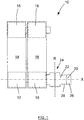
- Fig. 1 shows a conveyor unit 10 with a first drive roller 12 for driving a guided via a first idler roller 15 first tape track 14 and a second drive roller 16 for driving a guided via a second idler roller 19 second tape track 18, wherein the first tape track 14 and the second Band track 18 parallel to each other and are each designed as an endless conveyor.
- the first drive roller 12 and the second drive roller 16 are arranged coaxially side by side on a common axis of rotation X.
- the conveyor unit 10 further comprises a first drive shaft 12 associated with the first drive shaft 20 which is driven via a first pulley 26 by a first belt drive, not shown, and a second drive roller 16 associated second drive shaft 22 via a second pulley 28 from a second not shown belt drive is driven.
- a clutch 24 is arranged, which is configured radially separable in a common parting plane R.
- the construction of the coupling 24 will be described below with reference to FIG Fig. 2 explained in more detail.
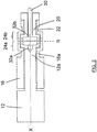
- Fig. 2 is a sectional view of the conveyor unit 10 along the axis of rotation X and shows how a first shaft portion 12a of the first drive roller 12 extends in sections within a second shaft portion 16a of the second drive roller 16. At their end faces remote from the drive rollers 12, 16, the shaft sections 12a, 16a together form a first coupling half 24a.
- the first drive shaft 20 extends in sections within the second drive shaft 22, wherein the drive shafts 20, 22 at their the drive rollers 12, 16 facing end faces one of the first coupling half 24a associated second coupling half 24b form.
- the coupling halves 24a, 24b are in Fig. 2 shown purely schematically and can form a positive connection, as in FIGS. 3A and 3B is shown in more detail.
- the coupling halves 24 a, 24 b allow a rotationally fixed coupling between the first shaft portion 12 a and the first drive shaft 20 and between the second shaft portion 16 a and the second drive shaft 22nd
- Fig. 2 further shows a centering pin 30 which engages through a first center hole 32a provided in the first shaft portion 12a and a second center hole 32b provided in the first drive shaft 20, and the drive rollers 12, 16, the shaft portions 12a, 16a and the drive shafts 20, 22 on the rotation axis X centered.
- the centering pin 30 is decoupled from the first drive shaft 20 and the first shaft portion 12a, ie the first drive shaft 20 and the first shaft portion 12a can rotate relative to the centering pin 30 and there is no torque transmission via the centering pin 30 instead.
- the centering pin 30 can be moved pneumatically or manually along the axis of rotation X.
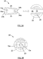
- Fig. 3 is a schematic representation of the coupling 24 in a separation or mounting position and on the one hand in a separate state ( Fig. 3A ), in which the coupling halves 24a, 24b are disengaged and can be brought into engagement, and on the other in an engaged state ( Fig. 3B ), in which the first shaft portion 12a and the first drive shaft 20 and the second shaft portion 16a and the second drive shaft 22 each form a positive connection.
- the first coupling half 24a has a wedge-shaped first coupling part seen in the radial direction, namely a wedge-shaped web 34
- the second coupling half 24b has a second coupling part formed by the first drive shaft 20 and the second drive shaft 22, seen in the radial direction
- a wedge-shaped web 34 includes a radially inner web portion 34a on the first shaft portion 12a and two the inner web portion 34a on both sides contours continuing pin 34b on the second shaft portion 16a.
- the wedge-shaped groove 36 extends along the diameter of the first and the second drive shaft 20, 22, so that the drive shafts 20, 22 form insertion bevels 38 for the wedge-shaped web 34.
- Obliquely extending contact surfaces 25 of the wedge-shaped web 34 are equipped with a damping material which can be provided as a plastic coating or as an easily replaceable wearing part. Alternatively or additionally, the damping material may be provided on the insertion bevels 38 of the wedge-shaped groove 36.
- the drive shafts 20, 22 and the shaft portions 12, 16 are aligned relative to each other such that the first coupling half 24 a the wedge-shaped web 34 and the second coupling half 24 b form the wedge-shaped groove 36.
- the coupling halves 24a, 24b are suitably rotated by means of a servo motor.
- at least one marking may be provided (not shown), by means of which a user can set the separation or mounting position of the coupling halves 24a, 24b manually.
- the first coupling half 24a is moved in the direction of the arrow until the contact surfaces 25 of the wedge-shaped web 34 engage with the insertion bevels 38 of the wedge-shaped groove 36. In this position, a rotation of the first shaft portion 12a and the first drive shaft 20 relative to the second shaft portion 16a and the second drive shaft 22 and thus an independent drive of the first and the second drive roller 12, 16 possible.
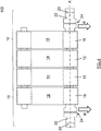
- Fig. 4 shows a transport device 100 with two conveyor units 10, the z. B. can be used in a high-performance slicer.
- the conveyor units 10 are arranged in mirror image side by side, that all four drive rollers 12, 16 and their shaft sections and the associated four drive shafts 20, 22 coaxially lie on the common axis of rotation X.
- the four tape tracks can be driven individually track, wherein the drive of the one pair of drive rollers 12, 16 from one side of the transport device 100 and the drive of the other pair of drive rollers 12, 16 takes place from the other side of the transport device 100 ago.
- the tape tracks 14, 18 and drive rollers 12, 16 are each a conveyor unit 10 or both conveyor units 10 are expanded simultaneously, for. B. for cleaning purposes, and then reinstalled.
Landscapes
- Engineering & Computer Science (AREA)
- Mechanical Engineering (AREA)
- Life Sciences & Earth Sciences (AREA)
- Forests & Forestry (AREA)
- Rollers For Roller Conveyors For Transfer (AREA)
Description
- Die vorliegende Erfindung betrifft eine Fördereinheit, welche eine einen ersten Wellenabschnitt aufweisende erste Antriebsrolle zum Antreiben einer ersten Bandspur und eine einen zweiten Wellenabschnitt aufweisende zweite Antriebsrolle zum Antreiben einer zweiten Bandspur umfasst, wobei die erste Antriebsrolle und die zweite Antriebsrolle koaxial nebeneinander angeordnet sind. Zum Antreiben der ersten Antriebsrolle umfasst die Fördereinheit eine erste Antriebswelle und zum Antreiben der zweiten Antriebsrolle eine zweite Antriebswelle.
- Derartige Fördereinheiten sind grundsätzlich bekannt und werden beispielsweise bei einer Lebensmittelschneidevorrichtung, insbesondere einem Hochleistungsslicer, als Produktauflage benutzt, z. B. für die Produktzufuhr. Bei einem Hochleistungsslicer werden in einer Schneidebene in der Regel mehrere Lebensmittelprodukte gleichzeitig geschnitten, die parallel zueinander relativ zur Schneidebene vorgeschoben werden. Bei früheren Hochleistungsslicern wurde der Vorschub mehrerer Lebensmittelprodukte durch einen gemeinsamen Bandantrieb realisiert. Mittlerweile erfolgt der Produktvorschub jedoch individuell, indem jedes Produkt auf einer eigenen unabhängig angetriebenen Bandspur vorgeschoben wird.
- Eine Fördereinheit gemäß dem Oberbegriff von Anspruch 1 ist aus der
US 5 163 543 A bekannt. - Solche Fördereinheiten sind aber durch das Vorsehen zusätzlicher Antriebseinheiten konstruktiv beschränkt und in der Montage, Wartung und Reinigung kompliziert. Es ist deshalb eine der Erfindung zugrunde liegende Aufgabe, eine mehrspurige Fördereinheit zu schaffen, welche die vorgenannten Nachteile überwindet.
- Diese Aufgabe wird durch eine Fördereinheit gemäß Anspruch 1 und insbesondere dadurch gelöst, dass der erste Wellenabschnitt zumindest abschnittsweise innerhalb des zweiten Wellenabschnitts verläuft, die erste Antriebswelle zumindest abschnittsweise innerhalb der zweiten Antriebswelle verläuft und eine Kupplung zur lösbaren Verbindung des ersten Wellenabschnitts mit der ersten Antriebswelle und des zweiten Wellenabschnitts mit der zweiten Antriebswelle in einer gemeinsamen Trennebene vorgesehen ist.
- Mit anderen Worten umfasst die erfindungsgemäße Fördereinheit zwei ineinander geschachtelte Antriebswellen, die jeweils über einen zugeordneten Wellenabschnitt mit einer entsprechenden Antriebsrolle verbindbar sind. Die gemeinsame Kupplung ermöglicht die Einleitung der Drehbewegungen beider Antriebsrollen von derselben Seite sowie eine einfache Trennung der Antriebsrollen von den Antriebswellen, insbesondere in radialer Richtung in Bezug auf die Drehachse. Demnach zeichnet sich die Fördereinheit durch eine kompakte Bauweise und einfache Bedienung aus, welche eine einfache und sichere Montage bzw. Demontage ermöglicht.
- Obwohl hier der Einfachheit halber von lediglich zwei ineinander verschachtelten Wellenabschnitten und Antriebswellen die Rede ist, versteht es sich, dass das Grundprinzip der Verschachtelung auf eine größere Anzahl von Antriebsrollen bzw. Wellenabschnitten und Antriebswellen übertragen werden kann. Beispielsweise können drei oder mehr Wellen ineinander angeordnet sein.
- Vorteilhafte Weiterbildungen der Erfindung sind der Beschreibung, den Zeichnungen sowie den Unteransprüchen zu entnehmen.
- Erfindungsgemäß sorgt die Kupplung für einen radial trennbaren Formschluss zwischen dem ersten Wellenabschnitt und der ersten Antriebswelle sowie dem zweiten Wellenabschnitt und der zweiten Antriebswelle. Dabei können insbesondere der erste Wellenabschnitt und der zweite Wellenabschnitt gemeinsam eine erste Kupplungshälfte ausbilden und die erste Antriebswelle und die zweite Antriebswelle gemeinsam eine an die erste Kupplungshälfte angepasste zweite Kupplungshälfte ausbilden. Bei einer korrekten Ausrichtung des ersten und des zweiten Wellenabschnittes bzw. der ersten und der zweiten Antriebswelle relativ zueinander kann die Trennung der Kupplung einfach und insbesondere werkzeuglos erfolgen.
- Bevorzugt weist die erste Kupplungshälfte ein durch den ersten Wellenabschnitt und den zweiten Wellenabschnitt gebildetes, in radialer Richtung gesehen keilförmiges erstes Kupplungsteil und die zweite Kupplungshälfte ein durch die erste Antriebswelle und die zweite Antriebswelle gebildetes, in radialer Richtung gesehen keilförmiges zweites Kupplungsteil auf. Diese keilförmige Ausgestaltung ermöglicht eine spielarme Verbindung der Kupplungshälften und eine vereinfachte Handhabung, insbesondere eine einfacheres Ineingriffbringen der Kupplungshälften.
- Insbesondere können das erste Kupplungsteil ein keilförmiger Steg und das zweite Kupplungsteil eine an den Steg angepasste Nut sein. Der keilförmige Steg umfasst beispielsweise einen radial inneren Stegabschnitt an dem ersten Wellenabschnitt sowie zwei den inneren Stegabschnitt beidseitig konturmäßig fortsetzende Zapfen an dem zweiten Wellenabschnitt. Dabei verläuft die keilförmige Nut entlang des Durchmessers der ersten und der zweiten Antriebswelle, sodass die Antriebswellen Einführungsschrägen für den keilförmigen Steg bilden.
- Gemäß einer weiteren Ausführungsform ist zumindest ein Teil einer Kontaktfläche der ersten und/oder zweiten Kupplungshälfte jeweils mit einem Dämpfungsmaterial, z. B. einem Kunststoffmaterial, versehen oder es besteht aus einem Dämpfungsmaterial. Beispielsweise kann das Dämpfungsmaterial als einfach auswechselbares Verschleißteil vorgesehen sein, oder eine Kontaktfläche der ersten und/oder zweiten Kupplungshälfte kann vollständig mit einem Dämpfungsmaterial, z. B. einem Kunststoffmaterial, überzogen sein.
- Die Kupplung kann ferner mittels eines die Kupplung auf einer Drehachse durchgreifenden Zentrierstiftes gegen eine Trennung verriegelbar sein. Für eine Verriegelung der Kupplung im Betriebszustand kann der Zentrierstift insbesondere manuell oder pneumatisch in axialer Richtung betätigbar sein derart, dass er die Kupplung durchgreift und axial zentriert.
- Zum Antreiben der Fördereinheit können gemäß einer weiteren Ausführungsform die erste Antriebswelle eine erste Riemenscheibe und die zweite Antriebswelle eine zweite Riemenscheibe tragen.
- Gemäß noch einer weiteren Ausführungsform ist ein Servomotor zur Rotation der Kupplung in eine Trennungs- bzw. Montagelage vorgesehen. Alternativ oder zusätzlich kann die Kupplung zumindest eine Markierung zur manuellen Einstellung der Kupplung in eine Trennungs- bzw. Montagelage umfassen. Durch diese Maßnahmen können sowohl die radial inneren und die radial äußeren Kupplungsteile einer jeweiligen Kupplungshälfte als auch die Kupplungshälften leicht derart miteinander ausgerichtet werden, dass die Kupplung radial in oder außer Eingriff gebracht werden kann.
- Weiterer Gegenstand der Erfindung ist eine Transportvorrichtung mit zwei Fördereinheiten, die spiegelbildlich derart angeordnet sind, dass die Antriebsrollen, die Wellenabschnitte und die Antriebswellen beider Fördereinheiten auf einer gemeinsamen Drehachse liegen. Hierdurch können je nach Ausbildung der Fördereinheiten insgesamt vier oder mehr unabhängig angetriebene Band- und Produktspuren realisiert werden, während die Fördereinheiten Platz sparend von entgegengesetzten Seiten der Transportvorrichtung her angetrieben werden.
- Ferner betrifft die Erfindung eine Lebensmittelschneidevorrichtung, insbesondere einen Hochleistungsslicer, mit mindestens einer erfindungsgemäßen Fördereinheit und/oder mindestens einer erfindungsgemäßen Transportvorrichtung.
- Die Ausführungen zu der erfindungsgemäßen Fördereinheit, insbesondere hinsichtlich Vorteilen und bevorzugten Ausführungsformen, gelten für die erfindungsgemäße Transportvorrichtung und den erfindungsgemäßen Hochleistungsslicer entsprechend.
- Nachfolgend wird die Erfindung rein beispielhaft unter Bezugnahme auf die Zeichnung beschrieben. Es zeigen:
- Fig. 1
- eine Draufsicht auf eine erste Ausführungsform einer erfindungsgemäßen Fördereinheit;
- Fig. 2
- eine Schnittansicht von Antriebsrollen, Wellenabschnitten, Antriebswellen und einer Kupplung der Fördereinheit von
Fig. 1 entlang einer Drehachse X; - Fig. 3A und 3B
- eine schematische Darstellung einer Kupplung zur Verbindung der Wellenabschnitte und der Antriebswellen in einer Trennlage und einer Montagelage; und
- Fig. 4
- eine Draufsicht auf eine erfindungsgemäße Transportvorrichtung.
-
Fig. 1 zeigt eine Fördereinheit 10 mit einer ersten Antriebsrolle 12 zum Antreiben einer über eine erste Leerlaufrolle 15 geführten ersten Bandspur 14 und einer zweiten Antriebsrolle 16 zum Antreiben einer über eine zweite Leerlaufrolle 19 geführten zweiten Bandspur 18, wobei die erste Bandspur 14 und die zweite Bandspur 18 parallel zueinander verlaufen und jeweils als Endlosförderer ausgebildet sind. Die erste Antriebsrolle 12 und die zweite Antriebsrolle 16 sind auf einer gemeinsamen Drehachse X koaxial nebeneinander angeordnet. - Die Fördereinheit 10 umfasst ferner eine der ersten Antriebsrolle 12 zugeordnete erste Antriebswelle 20, die über eine erste Riemenscheibe 26 von einem ersten nicht dargestellten Riemenantrieb angetrieben wird, sowie eine der zweiten Antriebsrolle 16 zugeordnete zweite Antriebswelle 22, die über eine zweite Riemenscheibe 28 von einem zweiten nicht dargestellten Riemenantrieb angetrieben wird.
- Zwischen den Antriebsrollen 12, 16 und den Antriebswellen 20, 22 ist eine Kupplung 24 angeordnet, die in einer gemeinsamen Trennebene R radial trennbar ausgestaltet ist. Die Konstruktion der Kupplung 24 wird nachfolgend anhand von
Fig. 2 näher erläutert. -
Fig. 2 ist eine Schnittansicht der Fördereinheit 10 entlang der Drehachse X und zeigt, wie ein erster Wellenabschnitt 12a der ersten Antriebsrolle 12 abschnittsweise innerhalb eines zweiten Wellenabschnittes 16a der zweiten Antriebsrolle 16 verläuft. An ihren den Antriebsrollen 12, 16 abgewandten Stirnseiten bilden die Wellenabschnitte 12a, 16a zusammen eine erste Kupplungshälfte 24a. Ähnlich verläuft die erste Antriebswelle 20 abschnittsweise innerhalb der zweiten Antriebswelle 22, wobei die Antriebswellen 20, 22 an ihren den Antriebsrollen 12, 16 zugewandten Stirnseiten eine der ersten Kupplungshälfte 24a zugeordnete zweite Kupplungshälfte 24b bilden. Die Kupplungshälften 24a, 24b sind inFig. 2 rein schematisch dargestellt und können einen Formschluss bilden, wie er inFig. 3A und 3B genauer dargestellt ist. Die Kupplungshälften 24a, 24b ermöglichen eine drehfeste Kupplung zwischen dem ersten Wellenabschnitt 12a und der ersten Antriebswelle 20 sowie zwischen dem zweiten Wellenabschnitt 16a und der zweiten Antriebswelle 22. -
Fig. 2 zeigt ferner einen Zentrierstift 30, der eine im ersten Wellenabschnitt 12a vorgesehene erste Zentrierbohrung 32a sowie eine in der ersten Antriebswelle 20 vorgesehene zweite Zentrierbohrung 32b durchgreift und die Antriebsrollen 12, 16, die Wellenabschnitte 12a, 16a und die Antriebswellen 20, 22 auf der Drehachse X zentriert. Gleichzeitig wird in dieser Betriebsposition durch den Zentrierstift 30 eine versehentliche Trennung der Kupplung 24 in der radialen Richtung verhindert. Der Zentrierstift 30 ist dabei von der ersten Antriebswelle 20 und dem ersten Wellenabschnitt 12a entkoppelt, d. h. die erste Antriebswelle 20 und der erste Wellenabschnitt 12a können relativ zum Zentrierstift 30 drehen und es findet keine Drehmomentübertragung über den Zentrierstift 30 statt. Zur Verriegelung bzw. Entriegelung der Kupplung 24 kann der Zentrierstift 30 pneumatisch oder manuell entlang der Drehachse X bewegt werden. -
Fig. 3 ist eine schematische Darstellung der Kupplung 24 in einer Trennungs- bzw. Montagelage und zwar zum einen in einem getrennten Zustand (Fig. 3A ), in welchem die Kupplungshälften 24a, 24b außer Eingriff stehen und in Eingriff gebracht werden können, und zum anderen in einem eingekuppelten Zustand (Fig. 3B ), in welchem der erste Wellenabschnitt 12a und die erste Antriebswelle 20 sowie der zweite Wellenabschnitt 16a und die zweite Antriebswelle 22 jeweils einen Formschluss bilden. - Die erste Kupplungshälfte 24a weist ein in radialer Richtung gesehen keilförmiges erstes Kupplungsteil, nämlich einen keilförmigen Steg 34, auf, wohingegen die zweite Kupplungshälfte 24b ein durch die erste Antriebswelle 20 und die zweite Antriebswelle 22 gebildetes, in radialer Richtung gesehen keilförmiges zweites Kupplungsteil aufweist, nämlich eine an den Steg 34 angepasste Nut 36. Der keilförmige Steg 34 umfasst einen radial inneren Stegabschnitt 34a an dem ersten Wellenabschnitt 12a sowie zwei den inneren Stegabschnitt 34a beidseitig konturmäßig fortsetzende Zapfen 34b an dem zweiten Wellenabschnitt 16a. Die keilförmige Nut 36 verläuft entlang des Durchmessers der ersten und der zweiten Antriebswelle 20, 22, sodass die Antriebswellen 20, 22 Einführungsschrägen 38 für den keilförmigen Steg 34 bilden.
- Schräg verlaufende Kontaktflächen 25 des keilförmigen Steges 34 sind mit einem Dämpfungsmaterial ausgestattet, welches als Kunststoffüberzug oder auch als ein einfach auswechselbares Verschleißteil vorgesehen werden kann. Alternativ oder zusätzlich kann das Dämpfungsmaterial an den Einführungsschrägen 38 der keilförmigen Nut 36 vorgesehen sein.
- In der in
Fig. 3 dargestellten Trennungs- bzw. Montagelage sind die Antriebswellen 20, 22 bzw. die Wellenabschnitte 12, 16 relativ zueinander derart ausgerichtet, dass die erste Kupplungshälfte 24a den keilförmigen Steg 34 und die zweite Kupplungshälfte 24b die keilförmige Nut 36 bilden. Hierzu können die Kupplungshälften 24a, 24b mittels eines Servomotors geeignet verdreht werden. Alternativ kann zumindest eine Markierung vorgesehen sein (nicht dargestellt), mittels der ein Benutzer die Trennungs- bzw. Montagelage der Kupplungshälften 24a, 24b manuell einstellen kann. - Zum Einkuppeln der Kupplungshälften 24a, 24b wird der keilförmige Steg 34 mit seinem sich verjüngendem Ende voraus in die keilförmige Nut 36 eingeführt. Die erste Kupplungshälfte 24a wird hierzu in Richtung des Pfeils bewegt, bis die Kontaktflächen 25 des keilförmigen Stegs 34 mit den Einführungsschrägen 38 der keilförmigen Nut 36 in Eingriff geraten. In dieser Lage ist eine Verdrehung des ersten Wellenabschnittes 12a und der ersten Antriebswelle 20 relativ zu dem zweiten Wellenabschnitt 16a und der zweiten Antriebswelle 22 und somit eine unabhängige Ansteuerung der ersten und der zweiten Antriebsrolle 12, 16 möglich.
-
Fig. 4 zeigt eine Transportvorrichtung 100 mit zwei Fördereinheiten 10, die z. B. in einem Hochleistungsslicer eingesetzt werden kann. In dieser Transportvorrichtung 100 sind die Fördereinheiten 10 spiegelbildlich derart nebeneinander angeordnet, dass alle vier Antriebsrollen 12, 16 sowie ihre Wellenabschnitte und die zugeordneten vier Antriebswellen 20, 22 koaxial auf der gemeinsamen Drehachse X liegen. Die vier Bandspuren lassen sich spurindividuell antreiben, wobei der Antrieb des einen Paars von Antriebsrollen 12, 16 von der einen Seite der Transportvorrichtung 100 und der Antrieb des anderen Paars von Antriebsrollen 12, 16 von der anderen Seite der Transportvorrichtung 100 her erfolgt. Mittels der Kupplungen 24 können die Bandspuren 14, 18 und Antriebsrollen 12, 16 jeweils einer Fördereinheit 10 oder auch beider Fördereinheiten 10 gleichzeitig ausgebaut werden, z. B. zu Reinigungszwecken, und anschließend wieder montiert werden. -
- 10
- Fördereinheit
- 12
- erste Antriebsrolle
- 12a
- erster Wellenabschnitt
- 14
- erste Bandspur
- 15
- erste Leerlaufrolle
- 16
- zweite Antriebsrolle
- 16a
- zweiter Wellenabschnitt
- 18
- zweite Bandspur
- 19
- zweite Leerlaufrolle
- 20
- erste Antriebswelle
- 22
- zweite Antriebswelle
- 24
- radial trennbare Kupplung
- 24a
- erste Kupplungshälfte
- 24b
- zweite Kupplungshälfte
- 25
- Kontaktfläche
- 26
- erste Riemenscheibe
- 28
- zweite Riemenscheibe
- 30
- Zentrierstift
- 32a, 32b
- Zentrierbohrung
- 34
- keilförmiger Steg
- 34a
- innerer Stegabschnitt
- 34b
- Zapfen
- 36
- keilförmige Nut
- 38
- Einführungsschrägen
- 100
- Transportvorrichtung
- R
- radiale Trennebene
- X
- Drehachse
Claims (11)
- Fördereinheit (10) miteiner einen ersten Wellenabschnitt (12a) aufweisenden ersten Antriebsrolle (12) zum Antreiben einer ersten Bandspur (14),einer einen zweiten Wellenabschnitt (16a) aufweisenden zweiten Antriebsrolle (16) zum Antreiben einer zweiten Bandspur (18), wobei die erste Antriebsrolle (12) und die zweite Antriebsrolle (16) koaxial nebeneinander angeordnet sind,einer ersten Antriebswelle (20) zum Antreiben der ersten Antriebsrolle (12) undeiner zweiten Antriebswelle (22) zum Antreiben der zweiten Antriebsrolle (16), wobeider erste Wellenabschnitt (12a) zumindest abschnittsweise innerhalb des zweiten Wellenabschnitts (16a) verläuft, unddie erste Antriebswelle (20) zumindest abschnittsweise innerhalb der zweiten Antriebswelle (22) verläuft,
dadurch gekennzeichnet, dasseine Kupplung (24) zur lösbaren Verbindung des ersten Wellenabschnitts (12a) mit der ersten Antriebswelle (20) und des zweiten Wellenabschnitts (16a) mit der zweiten Antriebswelle (22) in einer gemeinsamen Trennebene (R) vorgesehen ist unddie Kupplung (24) für einen radial trennbaren Formschluss zwischen dem ersten Wellenabschnitt (12a) und der ersten Antriebswelle (20) sowie dem zweiten Wellenabschnitt (16a) und der zweiten Antriebswelle (22) sorgt. - Fördereinheit (10) nach Anspruch 1,
dadurch gekennzeichnet, dass
der erste Wellenabschnitt (12a) und der zweite Wellenabschnitt (16a) gemeinsam eine erste Kupplungshälfte (24a) ausbilden und die erste Antriebswelle (20) und die zweite Antriebswelle (22) gemeinsam eine an die erste Kupplungshälfte (24a) angepasste zweite Kupplungshälfte (24b) ausbilden. - Fördereinheit (10) nach Anspruch 2,
dadurch gekennzeichnet, dass
die erste Kupplungshälfte (24a) ein durch den ersten Wellenabschnitt (12a) und den zweiten Wellenabschnitt (16a) gebildetes, in radialer Richtung gesehen keilförmiges erstes Kupplungsteil aufweist und die zweite Kupplungshälfte (24b) ein durch die erste Antriebswelle (20) und die zweite Antriebswelle (22) gebildetes, in radialer Richtung gesehen keilförmiges zweites Kupplungsteil aufweist. - Fördereinheit (10) nach Anspruch 3,
dadurch gekennzeichnet, dass
das erste Kupplungsteil ein Steg (34) ist und das zweite Kupplungsteil eine an den Steg (34) angepasste Nut (36) ist, insbesondere wobei sich der Steg (34) über eine Stirnseite der ersten Kupplungshälfte (24a) und die Nut (36) über eine Stirnseite der zweiten Kupplungshälfte (24b) erstreckt. - Fördereinheit (10) nach zumindest einem der Ansprüche 2 bis 4,
dadurch gekennzeichnet, dass zumindest ein Teil einer Kontaktfläche (25) der ersten und/oder zweiten Kupplungshälfte (24a, 24b) jeweils mit einem Dämpfungsmaterial, z. B. einem Kunststoffmaterial, versehen ist oder aus einem Dämpfungsmaterial besteht. - Fördereinheit (10) nach zumindest einem der vorstehenden Ansprüche,
dadurch gekennzeichnet, dass
die Kupplung (24) mittels eines die Kupplung (24) auf einer Drehachse (X) durchgreifenden Zentrierstiftes (30) gegen eine Trennung verriegelbar ist, wobei der Zentrierstift (30) insbesondere manuell oder pneumatisch in axialer Richtung betätigbar ist. - Fördereinheit (10) nach zumindest einem der vorstehenden Ansprüche,
dadurch gekennzeichnet, dass
die erste Antriebswelle (20) eine erste Riemenscheibe (26) trägt und die zweite Antriebswelle (22) eine zweite Riemenscheibe (28) trägt. - Fördereinheit (10) nach zumindest einem der Ansprüche 2 bis 7,
gekennzeichnet durch
einen Servomotor zur Rotation zumindest einer der Kupplungshälften (24a, 24b) in eine Trennungs- bzw. Montagelage. - Fördereinheit (10) nach zumindest einem der vorstehenden Ansprüche,
dadurch gekennzeichnet, dass
die Kupplung (24) zumindest eine Markierung zur manuellen Einstellung der Kupplung (24) in eine Trennungs- bzw. Montagelage umfasst. - Transportvorrichtung (100) mit zwei Fördereinheiten (10) nach zumindest einem der vorhergehenden Ansprüche, wobei die Fördereinheiten (10) spiegelbildlich derart angeordnet sind, dass die Antriebsrollen (12, 16), die Wellenabschnitte (12a, 16a) und die Antriebswellen (20, 22) beider Fördereinheiten (10) auf einer gemeinsamen Drehachse (X) liegen.
- Lebensmittelschneidevorrichtung, insbesondere Hochleistungsslicer, mit mindestens einer Fördereinheit (10) nach zumindest einem der vorhergehenden Ansprüche 1 bis 9 und/oder einer Transportvorrichtung (100) nach Anspruch 10.
Applications Claiming Priority (1)
| Application Number | Priority Date | Filing Date | Title |
|---|---|---|---|
| DE102016107997.9A DE102016107997A1 (de) | 2016-04-29 | 2016-04-29 | Fördereinheit |
Publications (2)
| Publication Number | Publication Date |
|---|---|
| EP3239076A1 EP3239076A1 (de) | 2017-11-01 |
| EP3239076B1 true EP3239076B1 (de) | 2019-05-08 |
Family
ID=58410153
Family Applications (1)
| Application Number | Title | Priority Date | Filing Date |
|---|---|---|---|
| EP17162363.0A Active EP3239076B1 (de) | 2016-04-29 | 2017-03-22 | Fördereinheit |
Country Status (2)
| Country | Link |
|---|---|
| EP (1) | EP3239076B1 (de) |
| DE (1) | DE102016107997A1 (de) |
Families Citing this family (3)
| Publication number | Priority date | Publication date | Assignee | Title |
|---|---|---|---|---|
| CN111824695B (zh) * | 2019-04-17 | 2024-09-06 | 梅特勒-托利多安全线有限公司 | 用于输送机系统的驱动辊组件和包括它的输送机系统 |
| US10988319B2 (en) | 2019-08-01 | 2021-04-27 | Intelligrated Headquarters, Llc | Multi-belt conveyor system with removable cartridges |
| DE102023101460B3 (de) | 2023-01-20 | 2024-07-18 | Sielaff GmbH & Co. KG Automatenbau Herrieden | Kopplungssystem sowie Kopplungsvorrichtung zur mechanischen Synchronisierung nebeneinander angeordneter Transportvorrichtungen sowie Verkaufsautomat und Verfahren zum Konfigurieren eines Kopplungssystems |
Family Cites Families (11)
| Publication number | Priority date | Publication date | Assignee | Title |
|---|---|---|---|---|
| US1085774A (en) * | 1911-02-25 | 1914-02-03 | Fred Wegner | Conveying and feeding mechanism. |
| JPS55139519A (en) * | 1979-04-18 | 1980-10-31 | Yokohama Rubber Co Ltd:The | Structure of coupling for duplex shaft |
| EP0128378B1 (de) * | 1983-05-16 | 1987-04-15 | Schröder Maschinenhandels- GmbH & Co KG | Fördereinrichtung zur stetigen Förderung |
| DE3438122A1 (de) * | 1984-10-18 | 1986-06-19 | Schröder Maschinenhandelsgesellschaft mbH & Co , Betriebskommanditgesellschaft, 3579 Frielendorf | Foerderanlagen aus sektionen von tragkonstruktionen und foerdereinrichtungen zur optimalen und einfachen umstellung des foerderortes, des foerderweges, zur aenderung der stuetzweiten bei hoher stabilitaet, zur konstruktiven anpassung an veraenderungen der zu transportierenden stoffe und gueter aller art unter verwendung standartisierter einzelelemente als bauteile |
| IT1242881B (it) * | 1990-12-03 | 1994-05-18 | Baumer Srl | Apparecchiatura per raggruppare articoli in disposizione di affiancamento trasversale e longitudinale in gruppi di quantita' variabile da alimentare in continuo a macchine imballatrici. |
| NL1031094C2 (nl) * | 2006-02-07 | 2007-08-08 | Vanderlande Ind Nederland | Transportinrichting. |
| US7806254B2 (en) * | 2006-09-25 | 2010-10-05 | Dematic Corp. | Belt conveyor and method |
| JP5106920B2 (ja) * | 2007-05-22 | 2012-12-26 | シブヤ精機株式会社 | フリートレイの方向整列装置 |
| WO2013191123A1 (ja) * | 2012-06-19 | 2013-12-27 | ニッタ株式会社 | シャフト用構造体、雄型部材、及び、雌型部材 |
| DE102012210703A1 (de) * | 2012-06-25 | 2014-01-02 | Weber Maschinenbau Gmbh Breidenbach | Handhabung von Portionen |
| DE102013206510A1 (de) * | 2012-12-03 | 2014-06-05 | Textor Maschinenbau GmbH | Hochleistungsaufschnittschneidemaschine mit zumindest einer entnehmbaren Bandkassette |
-
2016
- 2016-04-29 DE DE102016107997.9A patent/DE102016107997A1/de not_active Withdrawn
-
2017
- 2017-03-22 EP EP17162363.0A patent/EP3239076B1/de active Active
Non-Patent Citations (1)
| Title |
|---|
| None * |
Also Published As
| Publication number | Publication date |
|---|---|
| DE102016107997A1 (de) | 2017-11-02 |
| EP3239076A1 (de) | 2017-11-01 |
Similar Documents
| Publication | Publication Date | Title |
|---|---|---|
| EP3676186B1 (de) | Vorrichtung mit schnellwechsel tellerträger und verschiebbarer führungskurve | |
| DE2438442C2 (de) | Schlitzwerkzeug in einer Vorrichtung zur Herstellung von geschlitzten und gegebenenfalls gestreckten Blechen | |
| EP3239076B1 (de) | Fördereinheit | |
| DE102007049547A1 (de) | Maschine zur Herstellung von zusammengesetzten Filtern | |
| DE3148176C2 (de) | Vorrichtung zum Transportieren von Fördergut | |
| EP0149694B1 (de) | Friktionsrollenbahn | |
| EP3239075B1 (de) | Transportvorrichtung für artikelströme aus jeweils geordnet nacheinander transportierten artikeln und verfahren zur anpassung einer transportvorrichtung an verschieden breite artikel | |
| DE3445575C2 (de) | Vorrichtung zum Beabstanden und Umwenden von zwei koaxialen Zigarettenlängenabschnitten in einer Filterbestückungsmaschine | |
| EP0365976B1 (de) | Profiliermaschine | |
| CH668573A5 (de) | Bearbeitungszentrum fuer werkstuecke. | |
| EP2508298A1 (de) | Halte- und Antriebsvorrichtung für ein Rohrunterstützungselement | |
| DE3029143A1 (de) | Rotierende stanzvorrichtung | |
| DE3817898C2 (de) | Schneidevorrichtung | |
| DE2402101A1 (de) | Einrichtung zum verbinden des formzylinders einer rotationsdruckmaschine mit dessen antriebswelle | |
| EP0314888B1 (de) | Kupplungsvorrichtung für Greiferschienenabschnitte einer Transfereinrichtung | |
| DE3525656C2 (de) | ||
| EP1703156B1 (de) | Kupplung aus zwei verstellbaren Steckteilen | |
| DE2318353A1 (de) | Einrichtung zur seitenausrichtung des rollensterns an sogenannten autopastern von rollenrotationsdruckmaschinen | |
| EP1029640A2 (de) | Querbearbeiter für Lagenmaterial, insbesondere Querschneider für Papier | |
| DE112009001413B4 (de) | Walzmaschine zum Umformen von metallischen und/oder eisenhaltigen Werkstücken mit verstellbaren Walzen | |
| DE112009001393B4 (de) | Walzmaschine zum Umformen von metallischen und/oder eisenhaltigen Werkstücken und Verfahren zum Wechseln der Walzen oder der Walzwerkzeuge der Walzmaschine | |
| DE3021683C2 (de) | Walze für ein Doppel-Duo-Reversier-Walzgerüst | |
| DE2420584C3 (de) | Wickelmaschine für Bandmaterial o.dgl. | |
| DE10119181B4 (de) | Kraftübertragung, insbesondere für eine Maschinen-Arbeitseinheit zur Substrat-Bearbeitung | |
| DE528241C (de) | Mehrteilige Falzwalze fuer Papierfalzmaschinen |
Legal Events
| Date | Code | Title | Description |
|---|---|---|---|
| PUAI | Public reference made under article 153(3) epc to a published international application that has entered the european phase |
Free format text: ORIGINAL CODE: 0009012 |
|
| STAA | Information on the status of an ep patent application or granted ep patent |
Free format text: STATUS: THE APPLICATION HAS BEEN PUBLISHED |
|
| AK | Designated contracting states |
Kind code of ref document: A1 Designated state(s): AL AT BE BG CH CY CZ DE DK EE ES FI FR GB GR HR HU IE IS IT LI LT LU LV MC MK MT NL NO PL PT RO RS SE SI SK SM TR |
|
| AX | Request for extension of the european patent |
Extension state: BA ME |
|
| STAA | Information on the status of an ep patent application or granted ep patent |
Free format text: STATUS: REQUEST FOR EXAMINATION WAS MADE |
|
| 17P | Request for examination filed |
Effective date: 20180430 |
|
| RBV | Designated contracting states (corrected) |
Designated state(s): AL AT BE BG CH CY CZ DE DK EE ES FI FR GB GR HR HU IE IS IT LI LT LU LV MC MK MT NL NO PL PT RO RS SE SI SK SM TR |
|
| GRAP | Despatch of communication of intention to grant a patent |
Free format text: ORIGINAL CODE: EPIDOSNIGR1 |
|
| STAA | Information on the status of an ep patent application or granted ep patent |
Free format text: STATUS: GRANT OF PATENT IS INTENDED |
|
| RIC1 | Information provided on ipc code assigned before grant |
Ipc: B26D 7/32 20060101ALI20181001BHEP Ipc: F16D 1/02 20060101ALN20181001BHEP Ipc: B65G 23/24 20060101AFI20181001BHEP Ipc: B65G 15/50 20060101ALN20181001BHEP |
|
| INTG | Intention to grant announced |
Effective date: 20181023 |
|
| GRAS | Grant fee paid |
Free format text: ORIGINAL CODE: EPIDOSNIGR3 |
|
| GRAA | (expected) grant |
Free format text: ORIGINAL CODE: 0009210 |
|
| STAA | Information on the status of an ep patent application or granted ep patent |
Free format text: STATUS: THE PATENT HAS BEEN GRANTED |
|
| AK | Designated contracting states |
Kind code of ref document: B1 Designated state(s): AL AT BE BG CH CY CZ DE DK EE ES FI FR GB GR HR HU IE IS IT LI LT LU LV MC MK MT NL NO PL PT RO RS SE SI SK SM TR |
|
| REG | Reference to a national code |
Ref country code: GB Ref legal event code: FG4D Free format text: NOT ENGLISH |
|
| REG | Reference to a national code |
Ref country code: CH Ref legal event code: EP Ref country code: AT Ref legal event code: REF Ref document number: 1129803 Country of ref document: AT Kind code of ref document: T Effective date: 20190515 |
|
| REG | Reference to a national code |
Ref country code: IE Ref legal event code: FG4D Free format text: LANGUAGE OF EP DOCUMENT: GERMAN |
|
| REG | Reference to a national code |
Ref country code: DE Ref legal event code: R096 Ref document number: 502017001259 Country of ref document: DE |
|
| REG | Reference to a national code |
Ref country code: NL Ref legal event code: FP |
|
| REG | Reference to a national code |
Ref country code: LT Ref legal event code: MG4D |
|
| PG25 | Lapsed in a contracting state [announced via postgrant information from national office to epo] |
Ref country code: SE Free format text: LAPSE BECAUSE OF FAILURE TO SUBMIT A TRANSLATION OF THE DESCRIPTION OR TO PAY THE FEE WITHIN THE PRESCRIBED TIME-LIMIT Effective date: 20190508 Ref country code: ES Free format text: LAPSE BECAUSE OF FAILURE TO SUBMIT A TRANSLATION OF THE DESCRIPTION OR TO PAY THE FEE WITHIN THE PRESCRIBED TIME-LIMIT Effective date: 20190508 Ref country code: LT Free format text: LAPSE BECAUSE OF FAILURE TO SUBMIT A TRANSLATION OF THE DESCRIPTION OR TO PAY THE FEE WITHIN THE PRESCRIBED TIME-LIMIT Effective date: 20190508 Ref country code: FI Free format text: LAPSE BECAUSE OF FAILURE TO SUBMIT A TRANSLATION OF THE DESCRIPTION OR TO PAY THE FEE WITHIN THE PRESCRIBED TIME-LIMIT Effective date: 20190508 Ref country code: AL Free format text: LAPSE BECAUSE OF FAILURE TO SUBMIT A TRANSLATION OF THE DESCRIPTION OR TO PAY THE FEE WITHIN THE PRESCRIBED TIME-LIMIT Effective date: 20190508 Ref country code: NO Free format text: LAPSE BECAUSE OF FAILURE TO SUBMIT A TRANSLATION OF THE DESCRIPTION OR TO PAY THE FEE WITHIN THE PRESCRIBED TIME-LIMIT Effective date: 20190808 Ref country code: HR Free format text: LAPSE BECAUSE OF FAILURE TO SUBMIT A TRANSLATION OF THE DESCRIPTION OR TO PAY THE FEE WITHIN THE PRESCRIBED TIME-LIMIT Effective date: 20190508 Ref country code: PT Free format text: LAPSE BECAUSE OF FAILURE TO SUBMIT A TRANSLATION OF THE DESCRIPTION OR TO PAY THE FEE WITHIN THE PRESCRIBED TIME-LIMIT Effective date: 20190908 |
|
| PG25 | Lapsed in a contracting state [announced via postgrant information from national office to epo] |
Ref country code: GR Free format text: LAPSE BECAUSE OF FAILURE TO SUBMIT A TRANSLATION OF THE DESCRIPTION OR TO PAY THE FEE WITHIN THE PRESCRIBED TIME-LIMIT Effective date: 20190809 Ref country code: LV Free format text: LAPSE BECAUSE OF FAILURE TO SUBMIT A TRANSLATION OF THE DESCRIPTION OR TO PAY THE FEE WITHIN THE PRESCRIBED TIME-LIMIT Effective date: 20190508 Ref country code: RS Free format text: LAPSE BECAUSE OF FAILURE TO SUBMIT A TRANSLATION OF THE DESCRIPTION OR TO PAY THE FEE WITHIN THE PRESCRIBED TIME-LIMIT Effective date: 20190508 Ref country code: BG Free format text: LAPSE BECAUSE OF FAILURE TO SUBMIT A TRANSLATION OF THE DESCRIPTION OR TO PAY THE FEE WITHIN THE PRESCRIBED TIME-LIMIT Effective date: 20190808 |
|
| PG25 | Lapsed in a contracting state [announced via postgrant information from national office to epo] |
Ref country code: DK Free format text: LAPSE BECAUSE OF FAILURE TO SUBMIT A TRANSLATION OF THE DESCRIPTION OR TO PAY THE FEE WITHIN THE PRESCRIBED TIME-LIMIT Effective date: 20190508 Ref country code: EE Free format text: LAPSE BECAUSE OF FAILURE TO SUBMIT A TRANSLATION OF THE DESCRIPTION OR TO PAY THE FEE WITHIN THE PRESCRIBED TIME-LIMIT Effective date: 20190508 Ref country code: CZ Free format text: LAPSE BECAUSE OF FAILURE TO SUBMIT A TRANSLATION OF THE DESCRIPTION OR TO PAY THE FEE WITHIN THE PRESCRIBED TIME-LIMIT Effective date: 20190508 Ref country code: RO Free format text: LAPSE BECAUSE OF FAILURE TO SUBMIT A TRANSLATION OF THE DESCRIPTION OR TO PAY THE FEE WITHIN THE PRESCRIBED TIME-LIMIT Effective date: 20190508 Ref country code: SK Free format text: LAPSE BECAUSE OF FAILURE TO SUBMIT A TRANSLATION OF THE DESCRIPTION OR TO PAY THE FEE WITHIN THE PRESCRIBED TIME-LIMIT Effective date: 20190508 |
|
| REG | Reference to a national code |
Ref country code: DE Ref legal event code: R097 Ref document number: 502017001259 Country of ref document: DE |
|
| PG25 | Lapsed in a contracting state [announced via postgrant information from national office to epo] |
Ref country code: SM Free format text: LAPSE BECAUSE OF FAILURE TO SUBMIT A TRANSLATION OF THE DESCRIPTION OR TO PAY THE FEE WITHIN THE PRESCRIBED TIME-LIMIT Effective date: 20190508 Ref country code: IT Free format text: LAPSE BECAUSE OF FAILURE TO SUBMIT A TRANSLATION OF THE DESCRIPTION OR TO PAY THE FEE WITHIN THE PRESCRIBED TIME-LIMIT Effective date: 20190508 |
|
| PLBE | No opposition filed within time limit |
Free format text: ORIGINAL CODE: 0009261 |
|
| STAA | Information on the status of an ep patent application or granted ep patent |
Free format text: STATUS: NO OPPOSITION FILED WITHIN TIME LIMIT |
|
| PG25 | Lapsed in a contracting state [announced via postgrant information from national office to epo] |
Ref country code: TR Free format text: LAPSE BECAUSE OF FAILURE TO SUBMIT A TRANSLATION OF THE DESCRIPTION OR TO PAY THE FEE WITHIN THE PRESCRIBED TIME-LIMIT Effective date: 20190508 |
|
| 26N | No opposition filed |
Effective date: 20200211 |
|
| PG25 | Lapsed in a contracting state [announced via postgrant information from national office to epo] |
Ref country code: PL Free format text: LAPSE BECAUSE OF FAILURE TO SUBMIT A TRANSLATION OF THE DESCRIPTION OR TO PAY THE FEE WITHIN THE PRESCRIBED TIME-LIMIT Effective date: 20190508 |
|
| PG25 | Lapsed in a contracting state [announced via postgrant information from national office to epo] |
Ref country code: SI Free format text: LAPSE BECAUSE OF FAILURE TO SUBMIT A TRANSLATION OF THE DESCRIPTION OR TO PAY THE FEE WITHIN THE PRESCRIBED TIME-LIMIT Effective date: 20190508 |
|
| PG25 | Lapsed in a contracting state [announced via postgrant information from national office to epo] |
Ref country code: MC Free format text: LAPSE BECAUSE OF FAILURE TO SUBMIT A TRANSLATION OF THE DESCRIPTION OR TO PAY THE FEE WITHIN THE PRESCRIBED TIME-LIMIT Effective date: 20190508 |
|
| REG | Reference to a national code |
Ref country code: CH Ref legal event code: PL |
|
| REG | Reference to a national code |
Ref country code: BE Ref legal event code: MM Effective date: 20200331 |
|
| PG25 | Lapsed in a contracting state [announced via postgrant information from national office to epo] |
Ref country code: LU Free format text: LAPSE BECAUSE OF NON-PAYMENT OF DUE FEES Effective date: 20200322 |
|
| PG25 | Lapsed in a contracting state [announced via postgrant information from national office to epo] |
Ref country code: LI Free format text: LAPSE BECAUSE OF NON-PAYMENT OF DUE FEES Effective date: 20200331 Ref country code: IE Free format text: LAPSE BECAUSE OF NON-PAYMENT OF DUE FEES Effective date: 20200322 Ref country code: CH Free format text: LAPSE BECAUSE OF NON-PAYMENT OF DUE FEES Effective date: 20200331 |
|
| PG25 | Lapsed in a contracting state [announced via postgrant information from national office to epo] |
Ref country code: BE Free format text: LAPSE BECAUSE OF NON-PAYMENT OF DUE FEES Effective date: 20200331 |
|
| PG25 | Lapsed in a contracting state [announced via postgrant information from national office to epo] |
Ref country code: MT Free format text: LAPSE BECAUSE OF FAILURE TO SUBMIT A TRANSLATION OF THE DESCRIPTION OR TO PAY THE FEE WITHIN THE PRESCRIBED TIME-LIMIT Effective date: 20190508 Ref country code: CY Free format text: LAPSE BECAUSE OF FAILURE TO SUBMIT A TRANSLATION OF THE DESCRIPTION OR TO PAY THE FEE WITHIN THE PRESCRIBED TIME-LIMIT Effective date: 20190508 |
|
| PG25 | Lapsed in a contracting state [announced via postgrant information from national office to epo] |
Ref country code: MK Free format text: LAPSE BECAUSE OF FAILURE TO SUBMIT A TRANSLATION OF THE DESCRIPTION OR TO PAY THE FEE WITHIN THE PRESCRIBED TIME-LIMIT Effective date: 20190508 Ref country code: IS Free format text: LAPSE BECAUSE OF FAILURE TO SUBMIT A TRANSLATION OF THE DESCRIPTION OR TO PAY THE FEE WITHIN THE PRESCRIBED TIME-LIMIT Effective date: 20190908 |
|
| PGFP | Annual fee paid to national office [announced via postgrant information from national office to epo] |
Ref country code: FR Payment date: 20230320 Year of fee payment: 7 |
|
| REG | Reference to a national code |
Ref country code: AT Ref legal event code: MM01 Ref document number: 1129803 Country of ref document: AT Kind code of ref document: T Effective date: 20220322 |
|
| PGFP | Annual fee paid to national office [announced via postgrant information from national office to epo] |
Ref country code: GB Payment date: 20230323 Year of fee payment: 7 |
|
| P01 | Opt-out of the competence of the unified patent court (upc) registered |
Effective date: 20230522 |
|
| PGFP | Annual fee paid to national office [announced via postgrant information from national office to epo] |
Ref country code: NL Payment date: 20230322 Year of fee payment: 7 |
|
| PG25 | Lapsed in a contracting state [announced via postgrant information from national office to epo] |
Ref country code: AT Free format text: LAPSE BECAUSE OF NON-PAYMENT OF DUE FEES Effective date: 20220322 |
|
| REG | Reference to a national code |
Ref country code: NL Ref legal event code: HC Owner name: WEBER FOOD TECHNOLOGY GMBH; DE Free format text: DETAILS ASSIGNMENT: CHANGE OF OWNER(S), CHANGE OF OWNER(S) NAME; FORMER OWNER NAME: WEBER MASCHINENBAU GMBH BREIDENBACH Effective date: 20240206 |
|
| REG | Reference to a national code |
Ref country code: DE Ref legal event code: R081 Ref document number: 502017001259 Country of ref document: DE Owner name: WEBER FOOD TECHNOLOGY SE & CO. KG, DE Free format text: FORMER OWNER: WEBER MASCHINENBAU GMBH BREIDENBACH, 35236 BREIDENBACH, DE Ref country code: DE Ref legal event code: R081 Ref document number: 502017001259 Country of ref document: DE Owner name: WEBER FOOD TECHNOLOGY GMBH, DE Free format text: FORMER OWNER: WEBER MASCHINENBAU GMBH BREIDENBACH, 35236 BREIDENBACH, DE |
|
| REG | Reference to a national code |
Ref country code: NL Ref legal event code: MM Effective date: 20240401 |
|
| GBPC | Gb: european patent ceased through non-payment of renewal fee |
Effective date: 20240322 |
|
| PG25 | Lapsed in a contracting state [announced via postgrant information from national office to epo] |
Ref country code: NL Free format text: LAPSE BECAUSE OF NON-PAYMENT OF DUE FEES Effective date: 20240401 |
|
| PG25 | Lapsed in a contracting state [announced via postgrant information from national office to epo] |
Ref country code: NL Free format text: LAPSE BECAUSE OF NON-PAYMENT OF DUE FEES Effective date: 20240401 |
|
| PG25 | Lapsed in a contracting state [announced via postgrant information from national office to epo] |
Ref country code: GB Free format text: LAPSE BECAUSE OF NON-PAYMENT OF DUE FEES Effective date: 20240322 |
|
| PG25 | Lapsed in a contracting state [announced via postgrant information from national office to epo] |
Ref country code: FR Free format text: LAPSE BECAUSE OF NON-PAYMENT OF DUE FEES Effective date: 20240331 |
|
| PG25 | Lapsed in a contracting state [announced via postgrant information from national office to epo] |
Ref country code: GB Free format text: LAPSE BECAUSE OF NON-PAYMENT OF DUE FEES Effective date: 20240322 Ref country code: FR Free format text: LAPSE BECAUSE OF NON-PAYMENT OF DUE FEES Effective date: 20240331 |
|
| REG | Reference to a national code |
Ref country code: DE Ref legal event code: R081 Ref document number: 502017001259 Country of ref document: DE Owner name: WEBER FOOD TECHNOLOGY SE & CO. KG, DE Free format text: FORMER OWNER: WEBER FOOD TECHNOLOGY GMBH, 35236 BREIDENBACH, DE |
|
| PGFP | Annual fee paid to national office [announced via postgrant information from national office to epo] |
Ref country code: DE Payment date: 20260320 Year of fee payment: 10 |