EP3237708B1 - Ferrure destinée à être montée entre un battant et un cadre fixe d'une fenêtre, d'une porte ou similaire ainsi que fenêtre, porte ou similaire comprenant une ferrure de ce type - Google Patents
Ferrure destinée à être montée entre un battant et un cadre fixe d'une fenêtre, d'une porte ou similaire ainsi que fenêtre, porte ou similaire comprenant une ferrure de ce type Download PDFInfo
- Publication number
- EP3237708B1 EP3237708B1 EP15813077.3A EP15813077A EP3237708B1 EP 3237708 B1 EP3237708 B1 EP 3237708B1 EP 15813077 A EP15813077 A EP 15813077A EP 3237708 B1 EP3237708 B1 EP 3237708B1
- Authority
- EP
- European Patent Office
- Prior art keywords
- axis
- retaining
- sash
- fitting
- tilt
- Prior art date
- Legal status (The legal status is an assumption and is not a legal conclusion. Google has not performed a legal analysis and makes no representation as to the accuracy of the status listed.)
- Active
Links
- 230000008878 coupling Effects 0.000 claims description 47
- 238000010168 coupling process Methods 0.000 claims description 47
- 238000005859 coupling reaction Methods 0.000 claims description 47
- 238000006073 displacement reaction Methods 0.000 claims description 32
- 238000009434 installation Methods 0.000 claims description 3
- 210000002105 tongue Anatomy 0.000 description 20
- 235000001674 Agaricus brunnescens Nutrition 0.000 description 15
- 230000014759 maintenance of location Effects 0.000 description 9
- 230000000452 restraining effect Effects 0.000 description 4
- 238000010276 construction Methods 0.000 description 3
- 230000001788 irregular Effects 0.000 description 2
- 235000003332 Ilex aquifolium Nutrition 0.000 description 1
- 241000209027 Ilex aquifolium Species 0.000 description 1
- 238000005452 bending Methods 0.000 description 1
- 238000011109 contamination Methods 0.000 description 1
- 230000001419 dependent effect Effects 0.000 description 1
- 230000000694 effects Effects 0.000 description 1
- 238000003780 insertion Methods 0.000 description 1
- 230000037431 insertion Effects 0.000 description 1
- 238000000926 separation method Methods 0.000 description 1
- 241000894007 species Species 0.000 description 1
Images


Classifications
-
- E—FIXED CONSTRUCTIONS
- E05—LOCKS; KEYS; WINDOW OR DOOR FITTINGS; SAFES
- E05B—LOCKS; ACCESSORIES THEREFOR; HANDCUFFS
- E05B17/00—Accessories in connection with locks
- E05B17/20—Means independent of the locking mechanism for preventing unauthorised opening, e.g. for securing the bolt in the fastening position
- E05B17/2084—Means to prevent forced opening by attack, tampering or jimmying
-
- E—FIXED CONSTRUCTIONS
- E05—LOCKS; KEYS; WINDOW OR DOOR FITTINGS; SAFES
- E05C—BOLTS OR FASTENING DEVICES FOR WINGS, SPECIALLY FOR DOORS OR WINDOWS
- E05C17/00—Devices for holding wings open; Devices for limiting opening of wings or for holding wings open by a movable member extending between frame and wing; Braking devices, stops or buffers, combined therewith
- E05C17/02—Devices for holding wings open; Devices for limiting opening of wings or for holding wings open by a movable member extending between frame and wing; Braking devices, stops or buffers, combined therewith by mechanical means
- E05C17/04—Devices for holding wings open; Devices for limiting opening of wings or for holding wings open by a movable member extending between frame and wing; Braking devices, stops or buffers, combined therewith by mechanical means with a movable bar or equivalent member extending between frame and wing
- E05C17/12—Devices for holding wings open; Devices for limiting opening of wings or for holding wings open by a movable member extending between frame and wing; Braking devices, stops or buffers, combined therewith by mechanical means with a movable bar or equivalent member extending between frame and wing consisting of a single rod
- E05C17/16—Devices for holding wings open; Devices for limiting opening of wings or for holding wings open by a movable member extending between frame and wing; Braking devices, stops or buffers, combined therewith by mechanical means with a movable bar or equivalent member extending between frame and wing consisting of a single rod pivoted only at one end and having an elongated slot
- E05C17/166—Security devices
-
- E—FIXED CONSTRUCTIONS
- E05—LOCKS; KEYS; WINDOW OR DOOR FITTINGS; SAFES
- E05C—BOLTS OR FASTENING DEVICES FOR WINGS, SPECIALLY FOR DOORS OR WINDOWS
- E05C9/00—Arrangements of simultaneously actuated bolts or other securing devices at well-separated positions on the same wing
- E05C9/06—Arrangements of simultaneously actuated bolts or other securing devices at well-separated positions on the same wing with three or more sliding bars
- E05C9/063—Arrangements of simultaneously actuated bolts or other securing devices at well-separated positions on the same wing with three or more sliding bars extending along three or more sides of the wing or frame
- E05C9/066—Locks for windows or doors specially adapted for tilt and turn
-
- E—FIXED CONSTRUCTIONS
- E05—LOCKS; KEYS; WINDOW OR DOOR FITTINGS; SAFES
- E05C—BOLTS OR FASTENING DEVICES FOR WINGS, SPECIALLY FOR DOORS OR WINDOWS
- E05C9/00—Arrangements of simultaneously actuated bolts or other securing devices at well-separated positions on the same wing
- E05C9/18—Details of fastening means or of fixed retaining means for the ends of bars
- E05C9/1808—Keepers
Definitions
- the invention further relates to a window, a door or the like with a fitting of the above type.
- the locking bolt can pass through the insertion opening of the fitting part during a tilting opening movement of the window sash and the window sash can perform a tilting opening movement.
- An effective along the tilt axis of the sash supporting the window sash on the window frame is not possible by means of the fitting part and the wing-side locking pin due to the existing between the fitting part and the wing-side locking pin along the tilt axis game
- the fitting according to DE 10 2007 017 453 A1 is mounted between a wing rotatable about a vertical axis and a fixed frame of a window, a door, or the like, and includes a rotation opening limiting device that limits the rotation opening angle of the wing.
- the rotary opening limiting device has a coupling pin which can be moved on the leaf in the circumferential direction of the fold and a holding arm which is rotatably mounted on the fixed frame about a horizontal axis.
- the coupling pin engages perpendicular to the wing rotation axis in a guide slot of the support arm, which extends on the support arm in the radial direction of the support arm rotation axis.
- the object of the present invention is to provide a fitting which ensures a high burglar resistance of a wing of a window, a door or the like which can be tilted with a defined opening width.
- the claimed Kippö Wennsbegrenzungsvorraum comprises a securing arm, which is preferably rotatably mounted on the fixed frame about an axis of rotation parallel to the tilt axis of the wing and also a coupling element, which is preferably provided on the wing.
- the securing arm and the coupling element are mounted in particular on a rebate surface of the fixed frame and on a rebate surface of the wing, which is opposite in the closed position of the wing of the rebate surface of the fixed frame.
- tilt-open wing The risk that, for example, burglars want to gain access to provided with a window, a door or the like premises, exists in particular with tilt-open wing.
- the goal of the burglar is to move the wing away from the fixed frame beyond the tipping opening width.
- forces acting both vertically and parallel to the main plane of the relevant window, door or the like are exerted on a tilt-open wing.
- the wing Perpendicular to the main plane of the relevant window, the relevant door or the like, the wing can be acted upon by a burglar, for example in the region of the tilt axis.
- a burglar By levering the wing of the burglar wants to separate the wing kippachsseit of the fixed frame.
- Such a separation of the sash from the fixed frame is counteracted by the retention device according to the invention, which, when the sash is opened in a retention standby state, is in accordance with claim 1.
- the retaining element of the retaining device moves along the retaining arm of the retaining device, wherein the retaining arm is pivoted due to the relative to the fixed frame executed movement of the wing about its axis of rotation.
- the movement of the retaining element along the retaining arm and thus the movement of the wing away from the fixed frame ends as soon as the retainer of the retaining device becomes active and prevents continued movement of the retaining element along the retaining arm.
- the wing in response of the restraint of the invention has a distance from the fixed frame, which is too small than a burglar could penetrate through the gap between the wing and the fixed frame in the premises concerned.
- the tappet side forcibly separated from the fixed frame remains connected to the fixed frame via both the retaining device and the tipping opening limiting device, which likewise has anti-tampering properties.
- the fitting according to the invention according to claim 1 and provided with the fitting according to the invention window, the door provided therewith or the like according to claim 17 are therefore characterized by a high burglar resistance.
- Opening the tilt-open wing beyond the tilt opening width limited by the tilt-opening limiting device is possible by releasing the connection between the fixed frame and the wing made via the securing arm and the coupling element of the tilt-opening limiting device.
- a burglar may be endeavored for this purpose to cancel the effective along the tilt axis of the wing mutual support of the securing arm and the coupling element of Kippö Stammsvorraum. This could be accomplished by moving the wing relative to, for example, a lever-type burglary tool along the tilting axis is moved to the fixed frame. Such displacement of the wing along the tilt axis counteracts the anti-displacement device according to claim 2 according to claim.
- the mobility of the vane relative to the fixed frame along the tilting axis is at least limited by the cooperating securing elements of the anti-displacement device.
- movements of the wing along the tilting axis are completely prevented by the anti-displacement device and its securing elements.
- a fitting is provided in an advantageous embodiment of the invention, which is equipped with both a switchable restraint device according to claim 1 and with a switchable sliding safety.
- Claim 3 relates to a particularly burglar-proof design of the fitting according to the invention.
- the retaining element of the retaining device is designed as a mushroom pin, which engages the retaining arm of the retaining device in a guide slot with undercut longitudinal edges.
- a restraining arm is provided with a guide slot in a further development of the fitting according to the invention for the restraint, which has a groove bottom in the manner of a guide groove.
- the groove bottom covers the region of the guidance of the retaining element on the retaining arm of the retaining device to the outside.
- the retaining element of the retaining device is also used to lock the wing at the fixed frame at regular conditions (claim 5).
- closing piece with the retaining arm of the retaining device form a structural unit and rotatably support the retaining arm for this purpose (claim 6).
- a particularly strong connection of the striker to the associated component results when the striker is connected independently of the retaining arm with the associated component (claim 7). If the restraint arm is articulated on the closing piece and if the connection produced between the closing piece and the restraining arm for this purpose is load-bearing-capable, the connection of the restraining arm to the component provided with the closing piece is also particularly load-bearing and consequently burglar-proof.
- the closing piece in which engages the retaining element of the retaining device in the locked state of the fitting and on which in a preferred embodiment of the invention, the retaining arm of the retaining device is rotatably supported by means of at least one security screw the associated component can be screwed (claim 8).
- security screws come into question, such as screws with safety insert, tear-off screws or disposable screws, which can be rotated with conventional tools only in the tightening direction.
- the tilt-open wing associated retention standby state of the retainer according to the invention is prepared by the retaining element and / or the retaining arm of the retaining device is moved to a retention standby position or, from which the restraint device can respond when the wing performs an irregular tilt-axis movement relative to the fixed frame.
- Kippö Stammsvortechnische specified in the preamble of claim 1 species are basically able to act as restraints according to the invention due to their structural features. This circumstance carries the invention type according to claim 10 bill.
- the hardware processor it is possible to keep one and the same device for different applications in order to reduce its stock.
- the fitting part assembly is standardized.
- the restraint standby state of the restraint device and / or the securing state of the anti-slip device are inevitably established by transferring the armor from another functional state to the tilt-open state. Separate measures for switching the located in a non-functional state restraint device and / or located in an inoperative position anti-shunt in the functional state is not required accordingly.
- the sliding safety device connected in the securing state limits or completely prevents the mobility of the blade relative to the fixed frame along the tilting axis in both directions.
- the securing state of the anti-displacement device is brought about by moving the wing-side securing element and / or the fixed-frame-side securing element of the anti-displacement device along the tilting axis into a securing position.
- the switching of the anti-displacement device in the backup state can be integrated as a result, readily in the functionality of conventional window or door fittings.
- a drive rod of the fitting can be used, which can also serve to bring locking elements for locking and unlocking the wing on the fixed frame in and out of engagement.
- the anti-displacement device can be realized when a festrahmen butterer stop and as wing-side securing element a fixed-frame-side stop associated wing-side counter-stop are provided as a fixed-frame side fuse element.
- the stop on the fixed frame side limits in cooperation with the anti-roll-side stop, movements of the blade relative to the fixed frame along the tilting axis.
- wing-side counter-attacks fitting parts that can be used alternatively as a locking pin.
- fittings assembly can be standardized.
- mechanical devices can be used both for mounting of locking elements and for mounting fuse elements of the anti-displacement device according to the invention.
- the fitting according to the invention is characterized according to claim 13.
- the mobility of the wing relative to the fixed frame is preferably limited by means of components of the anti-displacement not only along the tilt axis but also in the transverse direction of the tilt axis or completely prevented.
- the one or more wing-side securing elements of the anti-slip device in backup state of the anti-slip device engages or engages behind a festritten workedes and in the transverse direction of the tilting axis abutment (claim 14).
- a fitting design according to the invention which has a securing pin as a wing-side counter-stop, is for fixing the wing in the transverse direction the tilting axis provided a securing pin with an enlarged in the radial direction of a pin axis pin head, which engages behind the fixed-frame-side abutment with the pin head.
- a securing pin can alternatively be used as a locking pin (mushroom pin).
- a wing-side counter-stop is provided as the wing-side securing element, which is moved to the securing position in the securing state in the transverse direction of the tilting axis in the securing position, the movement of the wing-side counter-attack for the production of the rear handle on an abutment effective in the transverse direction of the tilt axis abutment in addition to a component have a component along the tilting axis in the transverse direction of the tilting axis.
- Such a wing-side counter-stop coincides in terms of its kinematics with circular tongues, which are common as locking elements for locking a wing to a fixed frame.
- circular tongues which are common as locking elements for locking a wing to a fixed frame.
- a preferred embodiment of the invention is therefore used as a wing-side counter-attack usable in the rest as a locking element circular tongue.
- Such units are available in the form of conventional closing pieces for wing locking.
- a closing piece is used to at least limit the mobility of the tilt-open wing relative to the fixed frame both along the tilting axis and in the transverse direction of the tilting axis.
- At least one intermediate element is provided which extends in a gap between a vertical wing spar and the fixed frame opposite thereto, in particular in a folding gap, along the tilting axis. Also by such an intermediate element, the mobility of the wing is at least limited relative to the fixed frame along the tilt axis.
- intermediate elements along the tilt axis provided on both sides of the wing, so unwanted movements of the wing along the tilt axis in both directions are at least partially prevented.
- the coupling element of Kippö Stammsvortechnik is designed as a coupling pin which engages along the tilt axis with a mushroom head in a guide slot on the securing arm of Kippö Stammsbegrenzungsvorraum while the mushroom head engages behind the longitudinal edges of the guide slot on the securing arm.
- the coupling element of Kippö Stammsbegrenzungsvortechnisch for example, provided as a coupling element mushroom head, to ensure high security against burglary on Kippö Stammsvortechnik of the invention also serves to lock the wing to the fixed frame.
- the coupling element of the Kippö Stammsbegrenzungsvortechnisch is assigned to the other component of the window, the door or the like, a closing piece.
- the securing arm of the tilting opening limiting device is preferably rotatably mounted on this closing piece.
- a particularly strong connection between the striker and the device provided with the closing piece of the window, the door or the like is due to the fact that the striker is connected to the relevant component independently of the securing arm of Kippö Stammsbegrenzungsvorraum. Due to the special resilience of the connection between the striker and the associated therewith component is in accordance with load bearing rotary bearing of the securing arm of Kippö Stammsbegrenzungsvortechnisch on the striker the connection of the locking piece rotatably mounted on the securing arm to the provided with the striker component also particularly load-receptive.
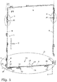
- FIG. 1 is a fitting 1 between a in FIG. 1 merely indicated wings 2 and a likewise only suggestively shown fixed frame 3 of a window 4 is provided.
- the fitting 1 is an espagnolette fitting whose wing-side fitting parts are accommodated in the usual manner in a fitting part groove which extends on the folding surface of the wing 2 in the wing circumferential direction.
- Assigned to the wing-side fitting parts of the fitting 1 are fixed-frame-side fitting parts which are arranged on the folding surface of the fixed frame 3 and are connected there to the fixed frame 3.
- wing-side espagnolette elements 6 of the fitting 1 are moved in the wing circumferential direction in a known manner. With the espagnolette elements 6 move fitting fittings that are thereby delivered relative to associated fixed frame side fitting parts. In this way, the fitting 1 in a in FIG. 1 and also in a tilt-open state and in a locked state.
- the lateral closing piece 9 is mounted on an opening-side vertical spar of the fixed frame 3 so that it can not be moved.
- Lower latch pins 10 on lower drive rod elements 6 are at the level of passage openings 11 which are provided on lower closing pieces 12 and which can be passed in the transverse direction of the main plane of the window 4 of the lower locking pin 10.
- the lower locking pins 10 are designed as a mushroom pin.
- Kippö Stamms Kunststoff of the fitting 1 the lower locking pins 10 are in itself along the tilting axis 16 extending and in FIG. 1 hinted recognizable longitudinal slots of the lower striker 12 run and now engage with their mushroom heads, the longitudinal edges of the guide slots on the lower strikers 12.
- the lower locking pins 10 are adjacent to a transversely extending the tilting axis 16 transverse boundary of the guide slots on the lower closing pieces 12 immediately adjacent.
- the circular tongue 17 of the circular tongue arrangement 13, which dips into the circular-tongue engagement 15, is in the immediate vicinity of an in FIG.
- the lower closing pieces 12 of the fitting 1 assume the function of tilting bearings for the wing 2.
- Intermediate elements in the form of lateral stop pieces 19 are arranged in the rebate spaces between the vertical beams of the wing 2 and the opposite vertical beams of the fixed frame 3 and provide a guide of the wing 2 in its pivotal movement about the tilting axis sixteenth
- the opening width of the tilted in the tilted opening position wing 2 is limited by two Kippö Stammsvortechniken 20 which are provided on the transverse in the transverse direction of the tilting axis 16 extending vertical beams of the wing 2 and the fixed frame 3 kippachsfern ( FIG. 1 ).
- each of the Kippö Stammsvortechnischen 20 includes a fixed frame side securing arm 21 and a wing-side coupling element in the form of a wing-side coupling pin 22 (FIG. Figures 4b, 4c ).
- the safety arm 21 is pivotally mounted on a mounting part 23.
- the mounting part 23 is bolted to the fixed frame 3 at the folding surface and also serves as a closing piece.
- the mounting member 23 is provided with a longitudinal slot 24 ( FIG. 3 ), whose longitudinal edges are undercut and in the locked state of the fitting 1 can be engaged behind by a mushroom head of the coupling pin 22. To get one in FIG.
- a guide slot 26 which serves to guide the wing-side coupling pin 22 and having undercut longitudinal edges.
- the longitudinal edges of the guide slot 26 can be engaged behind by the mushroom head of the coupling pin 22 designed as a mushroom pin.
- a shaft of the coupling pin 22 passes through an engagement opening 27 of the guide slot 26.
- FIG. 3 shows the unit of securing arm 21 and mounting member 23 in the view of that side, which faces in the installation position of the Kippö Stammsbegrenzungsvorraum 20 of the provided with the coupling pin 22 rebate surface of the wing 2.
- FIGS. 4a . 4b, 4c is the unit of securing arm 21 and mounting part 23 in the view of the viewer of FIG. 3 depicting the rear side of the arrangement. A lying towards the viewer groove base 30 of the guide slot 26 on the securing arm 21 is omitted for the sake of clarity.
- FIG. 4b shows the entire Kippö Stammsbegrenzungsvortechnisch 20 with the wing closed and 2 in the rotational opening state of the fitting 1.
- the securing arm 21 takes over the mounting part 23 its basic position in which it extends in the vertical direction.
- the attached to a wing-side espagnolette 6 coupling pin 22 is within a By rotation of the wing 2 about the vertical axis of rotation 7 of the wing 2 mitbewegte coupling pin 22 unhindered in the transverse direction of the main plane of the window 4 in the Recess recess 28 or leave the recess 28.
- FIGS. 4a . 4b, 4c the securing arm 21 is shown in the view on its space outside. There, the guide slot 26 of the securing arm 21 is covered by the sake of clarity, transparent groove bottom 30 shown.
- the swung in the tilted opening position wing 2 is particularly secure against burglary.
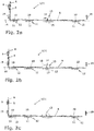
- FIG. 2a, 2b and 2c A special burglar security effect on the one hand in the Figures 2a, 2b and 2c shown in detail on the lower cross members of the wing 2 and the fixed frame 3.
- the lower locking pin 10 as a securing pin, the lower strikers 12 and the circular tongues arrangement 13 jointly form a switchable displacement lock 31, which ensures that the tilt-open wing 2 only at best slightly relative to the fixed frame 3 along the tilting axis 16 can be moved. In this case, the wing 2 is secured along the tilting axis 16 in both directions.
- the circular tongue engagement 15 act as a fixed-frame-side securing element or as festrahmen butterer stop and the circular tongue 17 of the circular tongue assembly 13 as a wing-side fuse element or switchable wing-side counter-attack of the anti-displacement device 31 together when the wing 2 forcibly in FIG. 2b is acted upon to the left.
- the circular tongue engagement 15 and the circular tongue 17 are effective as a stop and counter-stop, but with greater play along the tilt axis sixteenth
- a lateral displacement of the wing 2 in FIG. 2b to the right also acts in FIG. 2b right lateral stop piece 19, a lateral displacement of the wing 2 in FIG. 2b to the left in FIG. 2b left lateral stop piece 19 against.
- the lower closing pieces 12 form abutments, which are engaged behind by the lower locking pins 10, in particular by their mushroom heads.
- the rear grip of the circular tongue 17 on the circular tongue engagement 15 counteracts a displacement of the wing 2 relative to the fixed frame 3 in the transverse direction of the tilting axis 16.
- the Kippö Stammsbegrenzungsvortechnischen 20 contribute to the increased security against burglary of the wing 2.
- InQuery is on the one hand the fact that provided on the tilt-open wing 2 coupling pin 22 of each Kippö Stammsbegrenzungsvorraum 20 with its mushroom head, the longitudinal edges of the guide slot 26 on the associated fixed frame side Locking arm 21 engages behind and thereby counteracts a displacement of the wing 2 relative to the fixed frame 3 along the tilting axis 16.
- the connection made between the securing arm 21 and the fixed frame 3 via the mounting part 23 along the tilting axis 16 is particularly resilient.
- FIG. 1 shows the (dashed lines) handle 5 while down.
- the lateral locking pin 8 is engaged in the lateral locking piece 9, the lower locking pins 10 have due to the rotational operation of the handle 5, starting from their positions according to FIG. 2b the passages 11 of the lower striker 12 passes along the tilting axis 16 and are now in Figure 2c on the left side of the passage openings 11, where they engage behind with their mushroom heads the longitudinal edges of corresponding longitudinal slots on the lower closing pieces 12.
- the Kreiszeptan extract 13 takes over in the illustrated example, no locking function.
- the coupling pins 22 are in the longitudinal slots 24 of acting as closing pieces mounting parts 23 run in the locked state of the fitting 1.
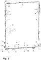
- FIG. 5 illustrated fitting 60 is correct in construction and operation largely with the fitting 1 according to FIG. 1 match. Modified relative to the fitting 1 is the switchable displacement lock 31 of the fitting 60.
- a Kreiszeptan extract 13 of in FIG. 1 shown type is not provided in the case of the fitting 60.
- a lateral displacement of the wing 2 relative to the fixed frame 3 act on the lower cross members of the wing 2 and the fixed frame 3 in tilt-open window 4 consequently only serve as wing-side securing elements lower locking pin 10 and the latter as fixed-frame-side securing elements associated lower strikers 12 of the fitting 60 against.
- the lower locking pins 10 and the lower strikers 12 of the safety securing device 31 of the fitting 60 jointly prevent unwanted displacement of the tilting wing 2 along the tilting axis 16 in FIG FIG. 5 to the right.
- switchable restraint 61 is provided at the location of the rotary tongue arrangement 1 according to FIG. 1 in the case of fitting no FIG. 5 strongly schematic and in FIG. 6 shown in detail switchable restraint 61 is provided.
- the retaining device 61 is identical in construction to the tilt-opening limiting devices 20 mounted on the window 4, which are tilt-remote.
- the retaining device 61 comprises a wing-side retaining element in the form of a retaining pin 62 and a retaining frame 63 on the fixed frame side.
- the retaining pin 62 is formed as a mushroom pin and attached to the displaceable along the lower transverse spar of the wing 2 espagnolette element 6, wherein the retaining pin 62 projects perpendicular to the rebate surface of the lower wing crossbar to the retaining arm 63 out.
- the retaining arm 63 is rotatably supported about a pivot axis 65 on a bearing part 64 corresponding to the mounting part 23 of the tilt-opening limiting device 20.
- the bearing member 64 is bolted to the lower cross member of the fixed frame 3 fixed to the folding surface.
- fastening screws safety screws of conventional design, not shown here, are used for the sake of simplicity.
- the axis of rotation 65 of the retaining arm 63 is perpendicular to the tilting axis 16 and parallel to the main plane of the window 4.
- the bearing member 64 also acts as a closing piece and is for this purpose with a longitudinal slot 66 with undercut longitudinal edges Mistake.
- the undercut longitudinal edges of the longitudinal slot 66 on the bearing part 64 can be engaged behind by a pin head 67, to which a pin shaft 68 of the retaining pin 62 is radially expanded.
- the retaining device 61 of the fitting 60 can be switched by rotary actuation of the handle 5 in different functional states.
- the wing-side retaining pin 62 in the in FIG. 6 shown in solid lines in an inlet 72 between the bearing part 64 and the retaining arm 63 of the retaining device 61. Due to its arrangement, the retaining pin 62 allows a rotational movement of the wing 2 about the vertical axis of rotation 7.
- the fitting 60 is switched from its rotational opening state into the tilt-open state while the wing 2 is still closed, and the handle 5 is rotated counterclockwise by 90 ° for this purpose from its horizontal orientation, the retaining pin 62 moves along the retaining arm 63 in FIG FIG. 6 to the right in the position immediately adjacent to its starting position, which in FIG. 6 is indicated by dashed lines on the right side of the retaining pin 62 shown in solid lines. Thereby, the retaining pin 62 is engaged with the guide slot 69 on the retaining arm 63. The retaining device 61 of the fitting 60 is thus in the retention standby state. In the restraint standby state, the restraint device 61 allows tilting movements of the wing 2 relative to the fixed frame 3.
- the restraint-ready state of the restraint 61 is assigned the tilt-open state of the bracket 60. Accordingly, the lower latch pins 10 are engaged along the tilting axis 16 in the lower strikers 12. In cooperation with the lower strikers 12, the lower latch pins 10 engaged in them secure the wing 2 against undesired displacement FIG. 5 to the right.
- the wing 2 Against a displacement perpendicular to the tilting axis 16 upwards, the wing 2 is secured to the fixed frame 3, since the lower locking pins 10 with their mushroom heads engage behind the longitudinal edges of the guide slots provided on the lower closing pieces 12 for the lower locking pins 10. And also perpendicular to the main plane of the window 4, the lower locking pins 10 in cooperation with the lower closing pieces 12 of the fitting located in Kippö Stammsschreib 60 cause a support of the wing 2 on the fixed frame. 3
- the retaining pin 62 of the retaining device 61 moves from its wooachsnahen position while pivoting the retaining arm 63 about the axis of rotation 65 along the retaining arm 63, until the retaining pin 62 abuts the transverse wall 70 of the guide slot 69.
- the retaining pin 62 is in FIG. 6 shown in dashed outline on the right.
- the transverse wall 70 of the retaining arm 63 prevents the now wooachsfern arranged retaining pin 62 a further violent Abstellterrorism of the retaining pin provided with the wing 2 with respect to the fixed frame.
- the restraint device 61 provides burglary protection of the type described above in detail for the tilt-opening limiting devices 20.
Landscapes
- Engineering & Computer Science (AREA)
- Mechanical Engineering (AREA)
- Hinges (AREA)
- Structures Of Non-Positive Displacement Pumps (AREA)
- Closing And Opening Devices For Wings, And Checks For Wings (AREA)
- Lock And Its Accessories (AREA)
- Power-Operated Mechanisms For Wings (AREA)
- Wing Frames And Configurations (AREA)
Claims (17)
- Ferrure destinée à être montée entre un battant (2) et un cadre fixe (3), qui sont prévus comme éléments structurels d'une fenêtre (4), d'une porte ou similaires,- sachant que la ferrure peut être passée dans un état d'ouverture basculante prévu comme état d'ouverture et définit dans l'état d'ouverture basculante, comme axe de pivotement, un axe de basculement (16) autour duquel, la ferrure étant montée, le battant (2) peut être pivoté par rapport au cadre fixe (3) dans une position d'ouverture sous la forme d'une position d'ouverture basculante et dans une position fermée,- sachant que la ferrure comprend, comme dispositif de limitation d'ouverture, un dispositif de limitation d'ouverture basculante (20), qui dans l'état monté est prévu entre un montant de battant s'étendant en direction transversale à l'axe de basculement (16) et un montant, opposé au précédent, du cadre fixe (3), et qui comprend un élément d'accouplement (22) prévu sur l'un des éléments structurels ainsi qu'un bras d'arrêt (21) prévu sur l'autre élément structurel, bras qui est mobile en rotation autour d'un axe de rotation (25) s'étendant parallèlement à l'axe de basculement (16),- sachant que, dans l'état d'ouverture basculante de la ferrure, lors du pivotement du battant (2) autour de l'axe de basculement (16), l'élément d'accouplement (22) du dispositif de limitation d'ouverture basculante (20) est guidé sur le bras d'arrêt (21) du dispositif de limitation d'ouverture basculante (20) en direction radiale à l'axe de rotation (25) du bras d'arrêt (21), et soutenu le long de l'axe de basculement (16),- sachant que, dans l'état d'ouverture basculante de la ferrure, l'élément d'accouplement (22) du dispositif de limitation d'ouverture basculante (20), est disposé près de l'axe de rotation (25) du bras d'arrêt (21) dans la position fermée du battant (2) et loin de l'axe de rotation dans la position d'ouverture basculante du battant (2),- et sachant que le dispositif de limitation d'ouverture basculante (20) présente, pour l'élément d'accouplement (22) disposé loin de l'axe de rotation, un limiteur de déplacement (29) par lequel l'élément d'accouplement (22) disposé loin de l'axe de rotation, dans la position d'ouverture basculante du battant (2), est empêché de se déplacer en éloignement de l'axe de rotation (25) du bras d'arrêt (21), définissant ainsi une amplitude maximale d'ouverture basculante du battant,caractérisée
en ce que la ferrure comprend un dispositif de retenue (61) pouvant être commuté, qui dans l'état monté est prévu entre un montant de battant côté axe de basculement s'étendant parallèlement à l'axe de basculement (16) et un montant côté axe de basculement, opposé au précédent, du cadre fixe (3), et qui comprend un élément de retenue (62) prévu sur l'un des éléments structurels ainsi qu'un bras de retenue (63) prévu sur l'autre élément structurel, bras qui est rotatif autour d'un axe de rotation (65) qui s'étend perpendiculairement à l'axe de basculement (16) et parallèlement à un plan principal de la fenêtre (4), de la porte ou similaires,
en ce que le dispositif de retenue (61), dans l'état d'ouverture basculante de la ferrure et le battant (2) étant rattaché côté axe de basculement au cadre fixe (3), est passé dans un état prêt à la retenue, dans lequel l'élément de retenue (62) et le bras de retenue (63) sont disposés l'un par rapport à l'autre de telle sorte que l'élément de retenue (62) est disposé près de l'axe de rotation (65) du bras de retenue (63),
en ce que, lors d'un mouvement effectué par le battant (2) par rapport au cadre fixe (3) côté axe de basculement perpendiculairement au plan principal de la fenêtre (4), de la porte ou similaires, avec éloignement côté axe de basculement du battant (2) du cadre fixe (3), l'élément de retenue (62) est guidé en déplacement, en direction radiale à l'axe de rotation (65) du bras de retenue (63), dans une position éloignée de l'axe de rotation,
et en ce que, le battant (2) étant éloigné côté axe de basculement du cadre fixe (3), l'élément de retenue (62) disposé loin de l'axe de rotation est empêché par un moyen de retenue (70) du dispositif de retenue (61) de se déplacer en éloignement de l'axe de rotation (65) du bras de retenue (63), limitant ainsi la mobilité côté axe de basculement du battant (2) par rapport au cadre fixe (3). - Ferrure selon la revendication 1, caractérisée en ce que la ferrure comprend un dispositif antidéplacement (31) pouvant être commuté, qui dans l'état monté est prévu entre un montant de battant côté axe de basculement s'étendant parallèlement à l'axe de basculement (16) et un montant côté axe de basculement, opposé au précédent, du cadre fixe (3), et qui présente des éléments de blocage dont un est prévu sous forme d'élément de blocage côté battant (10, 17) associé au battant (2) et un autre sous forme d'élément de blocage côté cadre fixe (12, 15) associé au cadre fixe (3),
et en ce que le dispositif antidéplacement (31), dans la position d'ouverture basculante de la ferrure, est passé dans un état de blocage dans lequel la mobilité de l'élément de blocage côté battant (10, 17) par rapport à l'élément de blocage côté cadre fixe (12, 15) et de ce fait la mobilité du battant (2) par rapport au cadre fixe (3) le long de l'axe de basculement (16), est au moins limitée. - Ferrure selon l'une des revendications précédentes, caractérisée en ce que l'élément de retenue (62) du dispositif de retenue (61) est réalisé sous forme de tenon de retenue avec un corps de tenon (68) s'étendant perpendiculairement à l'axe de basculement (16) et parallèlement au plan principal de la fenêtre (4), de la porte ou similaires et avec une tête de tenon (67) élargie par rapport au corps de tenon (68) parallèlement à l'axe de basculement (16), en ce qu'une fente de guidage (69) est prévue sur le bras de retenue (63) du dispositif de retenue (61) afin de guider le tenon de retenue en direction radiale à l'axe de rotation (65) du bras de retenue (63), fente dans laquelle le tenon de retenue s'engage perpendiculairement à l'axe de basculement (16) et qui présente des bords longitudinaux, qui s'étendent en direction radiale à l'axe de rotation (65) du bras de retenue (63) et qui sont contre-dépouillés, et en ce que le tenon de retenue est soutenu sur le bras de retenue (63) perpendiculairement à l'axe de basculement (16), par le fait que le tenon de retenue s'engage par la tête de tenon (67) derrière les bords longitudinaux de la fente de guidage (69) du bras de retenue (63).
- Ferrure selon la revendication 3, caractérisée en ce que la fente de guidage (69) sur le bras de retenue (63) du dispositif de retenue (61) est formée par une rainure de guidage avec un fond de rainure au moins partiellement fermé, qui est opposé à une ouverture d'engagement (71) de la rainure de guidage prévue pour l'élément de retenue (62) du dispositif de retenue (61) et, par son côté éloigné de l'ouverture d'engagement (71), est dirigé vers un côté extérieur du bras de retenue (63).
- Ferrure selon l'une des revendications précédentes, caractérisée en ce que la ferrure peut être passée dans un état de verrouillage et comprend une gâche (64) dans laquelle s'engage l'élément de retenue (62) du dispositif de retenue (61) dans l'état de verrouillage de la ferrure.
- Ferrure selon la revendication 5, caractérisée en ce que le bras de retenue (63) du dispositif de retenue (61) est monté sur la gâche (64) à rotation autour de l'axe de rotation (65) du bras de retenue (63).
- Ferrure selon la revendication 5 ou la revendication 6, caractérisée en ce que la gâche (64) peut, indépendamment du bras de retenue (63) du dispositif de retenue (61), être assemblée à l'élément structurel sur lequel est prévu le bras de retenue (63).
- Ferrure selon l'une des revendications 5 à 7, caractérisée en ce que la gâche (64), dans laquelle s'engage l'élément de retenue (62) du dispositif de retenue (61) dans l'état de verrouillage de la ferrure, peut être assemblée par vissage à l'élément structurel associé au moyen d'au moins une vis de sécurité.
- Ferrure selon l'une des revendications précédentes, caractérisée en ce que le dispositif de retenue (61) peut être passé dans l'état prêt à la retenue par le fait que l'élément de retenue (62) et/ou le bras de retenue (63) peut ou peuvent être déplacé(s) dans une position prête à la retenue, sachant que l'élément de retenue (62) déplacé dans la position prête à la retenue et/ou le bras de retenue (63) déplacé dans la position prête à la retenue sont disposés l'un par rapport à l'autre de telle sorte que l'élément de retenue (62), dans la position prête à la retenue, est disposé près de l'axe de rotation (65) du bras de retenue (63) et, lors d'un mouvement effectué par le battant (2) par rapport au cadre fixe (3) côté axe de basculement perpendiculairement au plan principal de la fenêtre (4), de la porte ou similaires, avec éloignement côté axe de basculement du battant (2) du cadre fixe (3), est guidé en déplacement, en direction radiale à l'axe de rotation (65) du bras de retenue (63), dans une position éloignée de l'axe de rotation.
- Ferrure selon l'une des revendications précédentes, caractérisée en ce qu'il est prévu comme dispositif de retenue (61) un dispositif pouvant être utilisé comme dispositif de limitation d'ouverture basculante (20).
- Ferrure selon l'une des revendications précédentes, caractérisée en ce que le dispositif de retenue (61) peut être passé dans l'état prêt à la retenue, et/ou le dispositif antidéplacement (31) dans l'état de blocage, par le fait que la ferrure peut être passée d'un autre état fonctionnel dans l'état d'ouverture basculante.
- Ferrure au moins selon la revendication 2, caractérisée en ce que le dispositif antidéplacement (31) peut être passé dans l'état de blocage par le fait que l'élément de blocage côté battant (10, 17) et/ou l'élément de blocage côté cadre fixe (12, 15) peut ou peuvent être déplacé(s) le long de l'axe de basculement (16) dans une position de blocage, sachant que, par l'élément de blocage côté battant (10, 17) déplacé dans la position de blocage et/ou par l'élément de blocage côté cadre fixe (12, 15) déplacé dans la position de blocage, la mobilité de l'élément de blocage côté battant (10, 17) par rapport à l'élément de blocage côté cadre fixe (12, 15) et de ce fait la mobilité du battant (2) par rapport au cadre fixe (3) le long de l'axe de basculement (16), est au moins limitée.
- Ferrure au moins selon la revendication 2, caractérisée en ce que, dans l'état de blocage du dispositif antidéplacement (31), de préférence au moyen de l'élément de blocage côté battant (10, 17) et/ou au moyen de l'élément de blocage côté cadre fixe (12, 15), la mobilité de l'élément de blocage côté battant (10, 17) par rapport à l'élément de blocage côté cadre fixe (12, 15) et de ce fait la mobilité du battant (2) par rapport au cadre fixe (3) est au moins limitée également en direction transversale à l'axe de basculement (16).
- Ferrure selon la revendication 13, caractérisée en ce que la mobilité du ou des éléments de blocage côté battant (10, 17) par rapport à l'élément ou aux éléments de blocage côté cadre fixe (12, 15) et de ce fait la mobilité du battant (2) par rapport au cadre fixe (3) en direction transversale à l'axe de basculement (16) est au moins limitée par le fait que le ou les éléments de blocage côté battant (10, 17), dans l'état de blocage du dispositif antidéplacement (31), s'engage ou s'engagent derrière un élément de contre-appui côté cadre fixe, actif en direction transversale à l'axe de basculement.
- Ferrure selon la revendication 14, caractérisée en ce que l'élément de blocage côté cadre fixe (12, 15) et l'élément de contre-appui côté cadre fixe pour l'élément de blocage côté battant (10, 17) forment une unité de construction.
- Ferrure au moins selon la revendication 2, caractérisée en ce que, en plus du dispositif antidéplacement (31) prévu dans l'état monté entre le montant de battant côté axe de basculement s'étendant parallèlement à l'axe de basculement (16) et le montant côté axe de basculement, opposé au précédent, du cadre fixe (3), un élément intermédiaire (19) est prévu entre au moins un montant de battant s'étendant en direction transversale à l'axe de basculement (16) et le montant, opposé au précédent, du cadre fixe (3), élément qui s'étend le long de l'axe de basculement (16) dans un espace intermédiaire entre le montant de battant s'étendant en direction transversale à l'axe de basculement (16) et le montant, opposé au précédent, du cadre fixe (3).
- Fenêtre, porte ou similaires avec un battant (2) et un cadre fixe (3) ainsi qu'avec une ferrure (60) prévue entre le battant (2) et le cadre fixe (3), qui peut être passée dans un état d'ouverture, sachant que le battant (2) peut, au moyen de la ferrure (60) passée dans un état d'ouverture, être pivoté par rapport au cadre fixe (3) autour d'un axe de pivotement dans une position fermée et dans une position d'ouverture, caractérisée en ce qu'il est prévu comme ferrure une ferrure (60) selon au moins une des revendications précédentes.
Priority Applications (2)
| Application Number | Priority Date | Filing Date | Title |
|---|---|---|---|
| PL15813077T PL3237708T3 (pl) | 2014-12-22 | 2015-12-21 | Okucie do montażu pomiędzy skrzydłem a nieruchomą ramą okna, drzwi lub tym podobnych oraz okno, drzwi lub tym podobne z takim okuciem |
| EP19194024.6A EP3613929A1 (fr) | 2014-12-22 | 2015-12-21 | Ferrure destinée à être installée entre un battant et un cadre fixe de fenêtre, porte ou analogue ainsi que fenêtre, porte ou analogue dotée d'une telle ferrure |
Applications Claiming Priority (2)
| Application Number | Priority Date | Filing Date | Title |
|---|---|---|---|
| DE102014226794.3A DE102014226794A1 (de) | 2014-12-22 | 2014-12-22 | Beschlag zum Einbau zwischen einem Flügel und einem festen Rahmen eines Fensters, einer Tür oder dergleichen sowie Fenster, Tür oder dergleichen mit einem derartigen Beschlag |
| PCT/EP2015/080806 WO2016102476A1 (fr) | 2014-12-22 | 2015-12-21 | Ferrure destinée à être montée entre un battant et un cadre fixe d'une fenêtre, d'une porte ou similaire ainsi que fenêtre, porte ou similaire comprenant une ferrure de ce type |
Related Child Applications (2)
| Application Number | Title | Priority Date | Filing Date |
|---|---|---|---|
| EP19194024.6A Division-Into EP3613929A1 (fr) | 2014-12-22 | 2015-12-21 | Ferrure destinée à être installée entre un battant et un cadre fixe de fenêtre, porte ou analogue ainsi que fenêtre, porte ou analogue dotée d'une telle ferrure |
| EP19194024.6A Division EP3613929A1 (fr) | 2014-12-22 | 2015-12-21 | Ferrure destinée à être installée entre un battant et un cadre fixe de fenêtre, porte ou analogue ainsi que fenêtre, porte ou analogue dotée d'une telle ferrure |
Publications (2)
| Publication Number | Publication Date |
|---|---|
| EP3237708A1 EP3237708A1 (fr) | 2017-11-01 |
| EP3237708B1 true EP3237708B1 (fr) | 2019-10-09 |
Family
ID=54884069
Family Applications (2)
| Application Number | Title | Priority Date | Filing Date |
|---|---|---|---|
| EP19194024.6A Pending EP3613929A1 (fr) | 2014-12-22 | 2015-12-21 | Ferrure destinée à être installée entre un battant et un cadre fixe de fenêtre, porte ou analogue ainsi que fenêtre, porte ou analogue dotée d'une telle ferrure |
| EP15813077.3A Active EP3237708B1 (fr) | 2014-12-22 | 2015-12-21 | Ferrure destinée à être montée entre un battant et un cadre fixe d'une fenêtre, d'une porte ou similaire ainsi que fenêtre, porte ou similaire comprenant une ferrure de ce type |
Family Applications Before (1)
| Application Number | Title | Priority Date | Filing Date |
|---|---|---|---|
| EP19194024.6A Pending EP3613929A1 (fr) | 2014-12-22 | 2015-12-21 | Ferrure destinée à être installée entre un battant et un cadre fixe de fenêtre, porte ou analogue ainsi que fenêtre, porte ou analogue dotée d'une telle ferrure |
Country Status (6)
| Country | Link |
|---|---|
| EP (2) | EP3613929A1 (fr) |
| CN (1) | CN107109857B (fr) |
| DE (1) | DE102014226794A1 (fr) |
| PL (1) | PL3237708T3 (fr) |
| RU (1) | RU2694909C2 (fr) |
| WO (1) | WO2016102476A1 (fr) |
Families Citing this family (2)
| Publication number | Priority date | Publication date | Assignee | Title |
|---|---|---|---|---|
| DE102017208059A1 (de) | 2017-05-12 | 2018-11-15 | Roto Frank Ag | Fenster oder Tür mit einbruchsicherer Kippöffnungsbegrenzung |
| EP4008863B1 (fr) | 2020-12-04 | 2023-08-02 | Ferco | Dispositif entrebâilleur pour menuiserie |
Citations (2)
| Publication number | Priority date | Publication date | Assignee | Title |
|---|---|---|---|---|
| US1628879A (en) * | 1924-07-21 | 1927-05-17 | Solar Polar Storm Sash And Scr | Window construction |
| DE102007017453A1 (de) * | 2007-04-02 | 2008-10-09 | Roto Frank Ag | Drehöffnungsbegrenzungsvorrichtung für einen Flügel eines Fensters oder dergleichen |
Family Cites Families (14)
| Publication number | Priority date | Publication date | Assignee | Title |
|---|---|---|---|---|
| DE3041511A1 (de) * | 1980-11-04 | 1982-05-13 | Ernst Selve GmbH & Co KG, 5880 Lüdenscheid | Dreh-kipp-beschlag fuer fenster, tueren o.dgl. |
| DE3939043C2 (de) * | 1989-11-25 | 1994-02-24 | Fuhr Carl Gmbh & Co | Beschlag für Fenster, Türen oder dergleichen |
| DE19518253C2 (de) * | 1995-05-18 | 1998-07-16 | Aubi Baubeschlaege Gmbh | Bandseitige Andrückvorrichtung zwischen einem drehbaren Flügel und einem Blendrahmen |
| DE19911893C2 (de) * | 1999-03-17 | 2002-05-08 | Siegenia Frank Kg | Beschlaganordnung |
| DE20200202U1 (de) * | 2002-01-08 | 2002-03-21 | Biffar Kg Oskar D | Fenster |
| DE10219692A1 (de) * | 2002-05-02 | 2003-11-27 | Roto Frank Ag | Verriegelungsbeschlag an einem Fenster, eienr Tür oder dergleichen, mit gegenläufig verschiebbaren Treibstangen |
| DE102004018062A1 (de) * | 2004-04-08 | 2005-10-27 | SCHÜCO International KG | Fenster oder Tür mit elektromechanischer Verriegelung |
| DE202006000292U1 (de) * | 2006-01-09 | 2006-03-16 | Siegenia-Aubi Kg | Ausstellvorrichtung |
| KR100808885B1 (ko) * | 2006-09-28 | 2008-03-03 | 김용석 | 열림 각도가 고정되는 회동식 창호 시스템 |
| DE202008016145U1 (de) * | 2008-12-08 | 2009-04-02 | Birkelbach, Irene | Sicherung der Dreh/Kipp-Fang-Schere |
| DE102009045735A1 (de) * | 2009-10-15 | 2011-04-21 | Aug. Winkhaus Gmbh & Co. Kg | Schließvorrichtung mit einem Schließblech zur Aufnahme eines Schließzapfens |
| CN102953637A (zh) * | 2012-11-24 | 2013-03-06 | 袁石楚 | 一种圆形旋转窗户 |
| DE102013203488A1 (de) * | 2013-03-01 | 2014-09-04 | Aug. Winkhaus Gmbh & Co. Kg | Öffnungsbegrenzer |
| CN203430231U (zh) * | 2013-07-25 | 2014-02-12 | 广东坚朗五金制品股份有限公司 | 滑撑 |
-
2014
- 2014-12-22 DE DE102014226794.3A patent/DE102014226794A1/de active Pending
-
2015
- 2015-12-21 WO PCT/EP2015/080806 patent/WO2016102476A1/fr active Application Filing
- 2015-12-21 PL PL15813077T patent/PL3237708T3/pl unknown
- 2015-12-21 CN CN201580069125.2A patent/CN107109857B/zh active Active
- 2015-12-21 EP EP19194024.6A patent/EP3613929A1/fr active Pending
- 2015-12-21 RU RU2017118554A patent/RU2694909C2/ru active
- 2015-12-21 EP EP15813077.3A patent/EP3237708B1/fr active Active
Patent Citations (2)
| Publication number | Priority date | Publication date | Assignee | Title |
|---|---|---|---|---|
| US1628879A (en) * | 1924-07-21 | 1927-05-17 | Solar Polar Storm Sash And Scr | Window construction |
| DE102007017453A1 (de) * | 2007-04-02 | 2008-10-09 | Roto Frank Ag | Drehöffnungsbegrenzungsvorrichtung für einen Flügel eines Fensters oder dergleichen |
Also Published As
| Publication number | Publication date |
|---|---|
| CN107109857B (zh) | 2019-12-13 |
| WO2016102476A1 (fr) | 2016-06-30 |
| DE102014226794A1 (de) | 2016-06-23 |
| EP3613929A1 (fr) | 2020-02-26 |
| RU2017118554A (ru) | 2019-01-24 |
| RU2694909C2 (ru) | 2019-07-18 |
| RU2017118554A3 (fr) | 2019-02-26 |
| EP3237708A1 (fr) | 2017-11-01 |
| CN107109857A (zh) | 2017-08-29 |
| PL3237708T3 (pl) | 2020-05-18 |
Similar Documents
| Publication | Publication Date | Title |
|---|---|---|
| EP3102759B1 (fr) | Ferrure d'un battant de fenêtres ou de portes, au moins relevable et coulissant | |
| EP3622139B1 (fr) | Fenêtre ou porte à limitation d'ouverture en basculement anti-effraction | |
| DE10134249A1 (de) | Verriegelungsbeschlag mit drehbarer Riegelleiste | |
| EP2594713B1 (fr) | Ouverture de porte | |
| EP3237708B1 (fr) | Ferrure destinée à être montée entre un battant et un cadre fixe d'une fenêtre, d'une porte ou similaire ainsi que fenêtre, porte ou similaire comprenant une ferrure de ce type | |
| EP3887621B1 (fr) | Système de fermeture modulaire | |
| EP1580381B1 (fr) | Ferrure de crémone | |
| EP1818489B1 (fr) | Fenêtre ou porte de sécurité inhibant l'effraction | |
| DE102008007095B4 (de) | Dreh-Kipp-Beschlag | |
| EP0601294B1 (fr) | Serrure complémentaire de securité pour battant de fenêtres, portes ou similaires | |
| EP4083360A2 (fr) | Fenêtre oscillo-battante et agencement de ferrure | |
| EP2772604A2 (fr) | Limiteur d'ouverture | |
| EP1754851B1 (fr) | Ferrure de basculement et de coulissement parallèle pour porte ou fenêtre et porte ou fenêtre avec une telle ferrure | |
| EP2947241B1 (fr) | Serrure à pêne pour un vantail de porte et procédé de montage | |
| DE19929818B4 (de) | Beschlag für ein Fenster oder eine Tür mit einer Spaltöffnungsstellung | |
| EP1715125A2 (fr) | Ferrures pour fenêtre oscillobattante avec une position pour créer une fente de ventilation | |
| EP2107194A1 (fr) | Limiteur d'ouverture pour une fenêtre ou une porte | |
| DE202019103122U1 (de) | Vorrichtung zur Sicherung von Fenstern oder Türen | |
| EP1970513B1 (fr) | Semi-fixe d'une porte à deux battants et dispositif de fermeture | |
| EP3626918B1 (fr) | Ferrure pour une fenêtre, fenêtre | |
| EP2348176B1 (fr) | Unité de verrouillage d'une ferrure à tringle | |
| EP1582672B1 (fr) | Renvoi d'angle pour ventilation réglable et limitation d'ouverture dans une condamnation centrale | |
| AT505570B1 (de) | Zarge mit falz für zumindest einen flügel | |
| EP1659241B1 (fr) | Ferrure pour dispositif anti-effraction de fenetre ou de porte a plusieurs vantaux | |
| EP2366853A2 (fr) | Agencement de sécurité pour portes coulissantes |
Legal Events
| Date | Code | Title | Description |
|---|---|---|---|
| STAA | Information on the status of an ep patent application or granted ep patent |
Free format text: STATUS: THE INTERNATIONAL PUBLICATION HAS BEEN MADE |
|
| PUAI | Public reference made under article 153(3) epc to a published international application that has entered the european phase |
Free format text: ORIGINAL CODE: 0009012 |
|
| STAA | Information on the status of an ep patent application or granted ep patent |
Free format text: STATUS: REQUEST FOR EXAMINATION WAS MADE |
|
| 17P | Request for examination filed |
Effective date: 20170724 |
|
| AK | Designated contracting states |
Kind code of ref document: A1 Designated state(s): AL AT BE BG CH CY CZ DE DK EE ES FI FR GB GR HR HU IE IS IT LI LT LU LV MC MK MT NL NO PL PT RO RS SE SI SK SM TR |
|
| AX | Request for extension of the european patent |
Extension state: BA ME |
|
| DAV | Request for validation of the european patent (deleted) | ||
| DAX | Request for extension of the european patent (deleted) | ||
| STAA | Information on the status of an ep patent application or granted ep patent |
Free format text: STATUS: EXAMINATION IS IN PROGRESS |
|
| 17Q | First examination report despatched |
Effective date: 20181024 |
|
| REG | Reference to a national code |
Ref country code: DE Ref legal event code: R079 Ref document number: 502015010636 Country of ref document: DE Free format text: PREVIOUS MAIN CLASS: E05B0017200000 Ipc: E06B0003380000 |
|
| GRAP | Despatch of communication of intention to grant a patent |
Free format text: ORIGINAL CODE: EPIDOSNIGR1 |
|
| STAA | Information on the status of an ep patent application or granted ep patent |
Free format text: STATUS: GRANT OF PATENT IS INTENDED |
|
| RIC1 | Information provided on ipc code assigned before grant |
Ipc: E06B 3/38 20060101AFI20190329BHEP |
|
| INTG | Intention to grant announced |
Effective date: 20190424 |
|
| RAP1 | Party data changed (applicant data changed or rights of an application transferred) |
Owner name: ROTO FRANK FENSTER- UND TUERTECHNOLOGIE GMBH |
|
| GRAS | Grant fee paid |
Free format text: ORIGINAL CODE: EPIDOSNIGR3 |
|
| GRAA | (expected) grant |
Free format text: ORIGINAL CODE: 0009210 |
|
| STAA | Information on the status of an ep patent application or granted ep patent |
Free format text: STATUS: THE PATENT HAS BEEN GRANTED |
|
| AK | Designated contracting states |
Kind code of ref document: B1 Designated state(s): AL AT BE BG CH CY CZ DE DK EE ES FI FR GB GR HR HU IE IS IT LI LT LU LV MC MK MT NL NO PL PT RO RS SE SI SK SM TR |
|
| REG | Reference to a national code |
Ref country code: GB Ref legal event code: FG4D Free format text: NOT ENGLISH |
|
| REG | Reference to a national code |
Ref country code: CH Ref legal event code: EP |
|
| REG | Reference to a national code |
Ref country code: IE Ref legal event code: FG4D Free format text: LANGUAGE OF EP DOCUMENT: GERMAN |
|
| REG | Reference to a national code |
Ref country code: DE Ref legal event code: R096 Ref document number: 502015010636 Country of ref document: DE |
|
| REG | Reference to a national code |
Ref country code: AT Ref legal event code: REF Ref document number: 1189007 Country of ref document: AT Kind code of ref document: T Effective date: 20191115 |
|
| REG | Reference to a national code |
Ref country code: NL Ref legal event code: MP Effective date: 20191009 |
|
| REG | Reference to a national code |
Ref country code: LT Ref legal event code: MG4D |
|
| PG25 | Lapsed in a contracting state [announced via postgrant information from national office to epo] |
Ref country code: LT Free format text: LAPSE BECAUSE OF FAILURE TO SUBMIT A TRANSLATION OF THE DESCRIPTION OR TO PAY THE FEE WITHIN THE PRESCRIBED TIME-LIMIT Effective date: 20191009 Ref country code: NL Free format text: LAPSE BECAUSE OF FAILURE TO SUBMIT A TRANSLATION OF THE DESCRIPTION OR TO PAY THE FEE WITHIN THE PRESCRIBED TIME-LIMIT Effective date: 20191009 Ref country code: LV Free format text: LAPSE BECAUSE OF FAILURE TO SUBMIT A TRANSLATION OF THE DESCRIPTION OR TO PAY THE FEE WITHIN THE PRESCRIBED TIME-LIMIT Effective date: 20191009 Ref country code: SE Free format text: LAPSE BECAUSE OF FAILURE TO SUBMIT A TRANSLATION OF THE DESCRIPTION OR TO PAY THE FEE WITHIN THE PRESCRIBED TIME-LIMIT Effective date: 20191009 Ref country code: PT Free format text: LAPSE BECAUSE OF FAILURE TO SUBMIT A TRANSLATION OF THE DESCRIPTION OR TO PAY THE FEE WITHIN THE PRESCRIBED TIME-LIMIT Effective date: 20200210 Ref country code: ES Free format text: LAPSE BECAUSE OF FAILURE TO SUBMIT A TRANSLATION OF THE DESCRIPTION OR TO PAY THE FEE WITHIN THE PRESCRIBED TIME-LIMIT Effective date: 20191009 Ref country code: NO Free format text: LAPSE BECAUSE OF FAILURE TO SUBMIT A TRANSLATION OF THE DESCRIPTION OR TO PAY THE FEE WITHIN THE PRESCRIBED TIME-LIMIT Effective date: 20200109 Ref country code: GR Free format text: LAPSE BECAUSE OF FAILURE TO SUBMIT A TRANSLATION OF THE DESCRIPTION OR TO PAY THE FEE WITHIN THE PRESCRIBED TIME-LIMIT Effective date: 20200110 Ref country code: BG Free format text: LAPSE BECAUSE OF FAILURE TO SUBMIT A TRANSLATION OF THE DESCRIPTION OR TO PAY THE FEE WITHIN THE PRESCRIBED TIME-LIMIT Effective date: 20200109 Ref country code: FI Free format text: LAPSE BECAUSE OF FAILURE TO SUBMIT A TRANSLATION OF THE DESCRIPTION OR TO PAY THE FEE WITHIN THE PRESCRIBED TIME-LIMIT Effective date: 20191009 |
|
| PG25 | Lapsed in a contracting state [announced via postgrant information from national office to epo] |
Ref country code: RS Free format text: LAPSE BECAUSE OF FAILURE TO SUBMIT A TRANSLATION OF THE DESCRIPTION OR TO PAY THE FEE WITHIN THE PRESCRIBED TIME-LIMIT Effective date: 20191009 Ref country code: IS Free format text: LAPSE BECAUSE OF FAILURE TO SUBMIT A TRANSLATION OF THE DESCRIPTION OR TO PAY THE FEE WITHIN THE PRESCRIBED TIME-LIMIT Effective date: 20200224 Ref country code: HR Free format text: LAPSE BECAUSE OF FAILURE TO SUBMIT A TRANSLATION OF THE DESCRIPTION OR TO PAY THE FEE WITHIN THE PRESCRIBED TIME-LIMIT Effective date: 20191009 |
|
| PG25 | Lapsed in a contracting state [announced via postgrant information from national office to epo] |
Ref country code: AL Free format text: LAPSE BECAUSE OF FAILURE TO SUBMIT A TRANSLATION OF THE DESCRIPTION OR TO PAY THE FEE WITHIN THE PRESCRIBED TIME-LIMIT Effective date: 20191009 |
|
| REG | Reference to a national code |
Ref country code: DE Ref legal event code: R097 Ref document number: 502015010636 Country of ref document: DE |
|
| PG2D | Information on lapse in contracting state deleted |
Ref country code: IS |
|
| PG25 | Lapsed in a contracting state [announced via postgrant information from national office to epo] |
Ref country code: DK Free format text: LAPSE BECAUSE OF FAILURE TO SUBMIT A TRANSLATION OF THE DESCRIPTION OR TO PAY THE FEE WITHIN THE PRESCRIBED TIME-LIMIT Effective date: 20191009 Ref country code: EE Free format text: LAPSE BECAUSE OF FAILURE TO SUBMIT A TRANSLATION OF THE DESCRIPTION OR TO PAY THE FEE WITHIN THE PRESCRIBED TIME-LIMIT Effective date: 20191009 Ref country code: RO Free format text: LAPSE BECAUSE OF FAILURE TO SUBMIT A TRANSLATION OF THE DESCRIPTION OR TO PAY THE FEE WITHIN THE PRESCRIBED TIME-LIMIT Effective date: 20191009 Ref country code: CZ Free format text: LAPSE BECAUSE OF FAILURE TO SUBMIT A TRANSLATION OF THE DESCRIPTION OR TO PAY THE FEE WITHIN THE PRESCRIBED TIME-LIMIT Effective date: 20191009 Ref country code: IS Free format text: LAPSE BECAUSE OF FAILURE TO SUBMIT A TRANSLATION OF THE DESCRIPTION OR TO PAY THE FEE WITHIN THE PRESCRIBED TIME-LIMIT Effective date: 20200209 |
|
| REG | Reference to a national code |
Ref country code: CH Ref legal event code: PL |
|
| PLBE | No opposition filed within time limit |
Free format text: ORIGINAL CODE: 0009261 |
|
| STAA | Information on the status of an ep patent application or granted ep patent |
Free format text: STATUS: NO OPPOSITION FILED WITHIN TIME LIMIT |
|
| REG | Reference to a national code |
Ref country code: BE Ref legal event code: MM Effective date: 20191231 |
|
| PG25 | Lapsed in a contracting state [announced via postgrant information from national office to epo] |
Ref country code: MC Free format text: LAPSE BECAUSE OF FAILURE TO SUBMIT A TRANSLATION OF THE DESCRIPTION OR TO PAY THE FEE WITHIN THE PRESCRIBED TIME-LIMIT Effective date: 20191009 Ref country code: SK Free format text: LAPSE BECAUSE OF FAILURE TO SUBMIT A TRANSLATION OF THE DESCRIPTION OR TO PAY THE FEE WITHIN THE PRESCRIBED TIME-LIMIT Effective date: 20191009 Ref country code: SM Free format text: LAPSE BECAUSE OF FAILURE TO SUBMIT A TRANSLATION OF THE DESCRIPTION OR TO PAY THE FEE WITHIN THE PRESCRIBED TIME-LIMIT Effective date: 20191009 |
|
| 26N | No opposition filed |
Effective date: 20200710 |
|
| GBPC | Gb: european patent ceased through non-payment of renewal fee |
Effective date: 20200109 |
|
| PG25 | Lapsed in a contracting state [announced via postgrant information from national office to epo] |
Ref country code: LU Free format text: LAPSE BECAUSE OF NON-PAYMENT OF DUE FEES Effective date: 20191221 Ref country code: GB Free format text: LAPSE BECAUSE OF NON-PAYMENT OF DUE FEES Effective date: 20200109 Ref country code: FR Free format text: LAPSE BECAUSE OF NON-PAYMENT OF DUE FEES Effective date: 20191231 Ref country code: IE Free format text: LAPSE BECAUSE OF NON-PAYMENT OF DUE FEES Effective date: 20191221 |
|
| PG25 | Lapsed in a contracting state [announced via postgrant information from national office to epo] |
Ref country code: BE Free format text: LAPSE BECAUSE OF NON-PAYMENT OF DUE FEES Effective date: 20191231 Ref country code: LI Free format text: LAPSE BECAUSE OF NON-PAYMENT OF DUE FEES Effective date: 20191231 Ref country code: SI Free format text: LAPSE BECAUSE OF FAILURE TO SUBMIT A TRANSLATION OF THE DESCRIPTION OR TO PAY THE FEE WITHIN THE PRESCRIBED TIME-LIMIT Effective date: 20191009 Ref country code: CH Free format text: LAPSE BECAUSE OF NON-PAYMENT OF DUE FEES Effective date: 20191231 |
|
| PG25 | Lapsed in a contracting state [announced via postgrant information from national office to epo] |
Ref country code: CY Free format text: LAPSE BECAUSE OF FAILURE TO SUBMIT A TRANSLATION OF THE DESCRIPTION OR TO PAY THE FEE WITHIN THE PRESCRIBED TIME-LIMIT Effective date: 20191009 |
|
| PG25 | Lapsed in a contracting state [announced via postgrant information from national office to epo] |
Ref country code: MT Free format text: LAPSE BECAUSE OF FAILURE TO SUBMIT A TRANSLATION OF THE DESCRIPTION OR TO PAY THE FEE WITHIN THE PRESCRIBED TIME-LIMIT Effective date: 20191009 Ref country code: HU Free format text: LAPSE BECAUSE OF FAILURE TO SUBMIT A TRANSLATION OF THE DESCRIPTION OR TO PAY THE FEE WITHIN THE PRESCRIBED TIME-LIMIT; INVALID AB INITIO Effective date: 20151221 |
|
| PG25 | Lapsed in a contracting state [announced via postgrant information from national office to epo] |
Ref country code: MK Free format text: LAPSE BECAUSE OF FAILURE TO SUBMIT A TRANSLATION OF THE DESCRIPTION OR TO PAY THE FEE WITHIN THE PRESCRIBED TIME-LIMIT Effective date: 20191009 |
|
| PGFP | Annual fee paid to national office [announced via postgrant information from national office to epo] |
Ref country code: TR Payment date: 20221220 Year of fee payment: 8 |
|
| PGFP | Annual fee paid to national office [announced via postgrant information from national office to epo] |
Ref country code: IT Payment date: 20221230 Year of fee payment: 8 |
|
| PGFP | Annual fee paid to national office [announced via postgrant information from national office to epo] |
Ref country code: DE Payment date: 20231214 Year of fee payment: 9 Ref country code: AT Payment date: 20231214 Year of fee payment: 9 |
|
| PGFP | Annual fee paid to national office [announced via postgrant information from national office to epo] |
Ref country code: PL Payment date: 20231208 Year of fee payment: 9 |