EP3237708B1 - Fitting for installing between a sash/leaf and a fixed frame of a window, a door or the like, and window, door or the like having such a fitting - Google Patents
Fitting for installing between a sash/leaf and a fixed frame of a window, a door or the like, and window, door or the like having such a fitting Download PDFInfo
- Publication number
- EP3237708B1 EP3237708B1 EP15813077.3A EP15813077A EP3237708B1 EP 3237708 B1 EP3237708 B1 EP 3237708B1 EP 15813077 A EP15813077 A EP 15813077A EP 3237708 B1 EP3237708 B1 EP 3237708B1
- Authority
- EP
- European Patent Office
- Prior art keywords
- axis
- retaining
- sash
- fitting
- tilt
- Prior art date
- Legal status (The legal status is an assumption and is not a legal conclusion. Google has not performed a legal analysis and makes no representation as to the accuracy of the status listed.)
- Active
Links
- 230000008878 coupling Effects 0.000 claims description 47
- 238000010168 coupling process Methods 0.000 claims description 47
- 238000005859 coupling reaction Methods 0.000 claims description 47
- 238000006073 displacement reaction Methods 0.000 claims description 32
- 238000009434 installation Methods 0.000 claims description 3
- 210000002105 tongue Anatomy 0.000 description 20
- 235000001674 Agaricus brunnescens Nutrition 0.000 description 15
- 230000014759 maintenance of location Effects 0.000 description 9
- 230000000452 restraining effect Effects 0.000 description 4
- 238000010276 construction Methods 0.000 description 3
- 230000001788 irregular Effects 0.000 description 2
- 235000003332 Ilex aquifolium Nutrition 0.000 description 1
- 241000209027 Ilex aquifolium Species 0.000 description 1
- 238000005452 bending Methods 0.000 description 1
- 238000011109 contamination Methods 0.000 description 1
- 230000001419 dependent effect Effects 0.000 description 1
- 230000000694 effects Effects 0.000 description 1
- 238000003780 insertion Methods 0.000 description 1
- 230000037431 insertion Effects 0.000 description 1
- 238000000926 separation method Methods 0.000 description 1
- 241000894007 species Species 0.000 description 1
Images


Classifications
-
- E—FIXED CONSTRUCTIONS
- E05—LOCKS; KEYS; WINDOW OR DOOR FITTINGS; SAFES
- E05B—LOCKS; ACCESSORIES THEREFOR; HANDCUFFS
- E05B17/00—Accessories in connection with locks
- E05B17/20—Means independent of the locking mechanism for preventing unauthorised opening, e.g. for securing the bolt in the fastening position
- E05B17/2084—Means to prevent forced opening by attack, tampering or jimmying
-
- E—FIXED CONSTRUCTIONS
- E05—LOCKS; KEYS; WINDOW OR DOOR FITTINGS; SAFES
- E05C—BOLTS OR FASTENING DEVICES FOR WINGS, SPECIALLY FOR DOORS OR WINDOWS
- E05C17/00—Devices for holding wings open; Devices for limiting opening of wings or for holding wings open by a movable member extending between frame and wing; Braking devices, stops or buffers, combined therewith
- E05C17/02—Devices for holding wings open; Devices for limiting opening of wings or for holding wings open by a movable member extending between frame and wing; Braking devices, stops or buffers, combined therewith by mechanical means
- E05C17/04—Devices for holding wings open; Devices for limiting opening of wings or for holding wings open by a movable member extending between frame and wing; Braking devices, stops or buffers, combined therewith by mechanical means with a movable bar or equivalent member extending between frame and wing
- E05C17/12—Devices for holding wings open; Devices for limiting opening of wings or for holding wings open by a movable member extending between frame and wing; Braking devices, stops or buffers, combined therewith by mechanical means with a movable bar or equivalent member extending between frame and wing consisting of a single rod
- E05C17/16—Devices for holding wings open; Devices for limiting opening of wings or for holding wings open by a movable member extending between frame and wing; Braking devices, stops or buffers, combined therewith by mechanical means with a movable bar or equivalent member extending between frame and wing consisting of a single rod pivoted only at one end and having an elongated slot
- E05C17/166—Security devices
-
- E—FIXED CONSTRUCTIONS
- E05—LOCKS; KEYS; WINDOW OR DOOR FITTINGS; SAFES
- E05C—BOLTS OR FASTENING DEVICES FOR WINGS, SPECIALLY FOR DOORS OR WINDOWS
- E05C9/00—Arrangements of simultaneously actuated bolts or other securing devices at well-separated positions on the same wing
- E05C9/06—Arrangements of simultaneously actuated bolts or other securing devices at well-separated positions on the same wing with three or more sliding bars
- E05C9/063—Arrangements of simultaneously actuated bolts or other securing devices at well-separated positions on the same wing with three or more sliding bars extending along three or more sides of the wing or frame
- E05C9/066—Locks for windows or doors specially adapted for tilt and turn
-
- E—FIXED CONSTRUCTIONS
- E05—LOCKS; KEYS; WINDOW OR DOOR FITTINGS; SAFES
- E05C—BOLTS OR FASTENING DEVICES FOR WINGS, SPECIALLY FOR DOORS OR WINDOWS
- E05C9/00—Arrangements of simultaneously actuated bolts or other securing devices at well-separated positions on the same wing
- E05C9/18—Details of fastening means or of fixed retaining means for the ends of bars
- E05C9/1808—Keepers
Definitions
- the invention further relates to a window, a door or the like with a fitting of the above type.
- the locking bolt can pass through the insertion opening of the fitting part during a tilting opening movement of the window sash and the window sash can perform a tilting opening movement.
- An effective along the tilt axis of the sash supporting the window sash on the window frame is not possible by means of the fitting part and the wing-side locking pin due to the existing between the fitting part and the wing-side locking pin along the tilt axis game
- the fitting according to DE 10 2007 017 453 A1 is mounted between a wing rotatable about a vertical axis and a fixed frame of a window, a door, or the like, and includes a rotation opening limiting device that limits the rotation opening angle of the wing.
- the rotary opening limiting device has a coupling pin which can be moved on the leaf in the circumferential direction of the fold and a holding arm which is rotatably mounted on the fixed frame about a horizontal axis.
- the coupling pin engages perpendicular to the wing rotation axis in a guide slot of the support arm, which extends on the support arm in the radial direction of the support arm rotation axis.
- the object of the present invention is to provide a fitting which ensures a high burglar resistance of a wing of a window, a door or the like which can be tilted with a defined opening width.
- the claimed Kippö Wennsbegrenzungsvorraum comprises a securing arm, which is preferably rotatably mounted on the fixed frame about an axis of rotation parallel to the tilt axis of the wing and also a coupling element, which is preferably provided on the wing.
- the securing arm and the coupling element are mounted in particular on a rebate surface of the fixed frame and on a rebate surface of the wing, which is opposite in the closed position of the wing of the rebate surface of the fixed frame.
- tilt-open wing The risk that, for example, burglars want to gain access to provided with a window, a door or the like premises, exists in particular with tilt-open wing.
- the goal of the burglar is to move the wing away from the fixed frame beyond the tipping opening width.
- forces acting both vertically and parallel to the main plane of the relevant window, door or the like are exerted on a tilt-open wing.
- the wing Perpendicular to the main plane of the relevant window, the relevant door or the like, the wing can be acted upon by a burglar, for example in the region of the tilt axis.
- a burglar By levering the wing of the burglar wants to separate the wing kippachsseit of the fixed frame.
- Such a separation of the sash from the fixed frame is counteracted by the retention device according to the invention, which, when the sash is opened in a retention standby state, is in accordance with claim 1.
- the retaining element of the retaining device moves along the retaining arm of the retaining device, wherein the retaining arm is pivoted due to the relative to the fixed frame executed movement of the wing about its axis of rotation.
- the movement of the retaining element along the retaining arm and thus the movement of the wing away from the fixed frame ends as soon as the retainer of the retaining device becomes active and prevents continued movement of the retaining element along the retaining arm.
- the wing in response of the restraint of the invention has a distance from the fixed frame, which is too small than a burglar could penetrate through the gap between the wing and the fixed frame in the premises concerned.
- the tappet side forcibly separated from the fixed frame remains connected to the fixed frame via both the retaining device and the tipping opening limiting device, which likewise has anti-tampering properties.
- the fitting according to the invention according to claim 1 and provided with the fitting according to the invention window, the door provided therewith or the like according to claim 17 are therefore characterized by a high burglar resistance.
- Opening the tilt-open wing beyond the tilt opening width limited by the tilt-opening limiting device is possible by releasing the connection between the fixed frame and the wing made via the securing arm and the coupling element of the tilt-opening limiting device.
- a burglar may be endeavored for this purpose to cancel the effective along the tilt axis of the wing mutual support of the securing arm and the coupling element of Kippö Stammsvorraum. This could be accomplished by moving the wing relative to, for example, a lever-type burglary tool along the tilting axis is moved to the fixed frame. Such displacement of the wing along the tilt axis counteracts the anti-displacement device according to claim 2 according to claim.
- the mobility of the vane relative to the fixed frame along the tilting axis is at least limited by the cooperating securing elements of the anti-displacement device.
- movements of the wing along the tilting axis are completely prevented by the anti-displacement device and its securing elements.
- a fitting is provided in an advantageous embodiment of the invention, which is equipped with both a switchable restraint device according to claim 1 and with a switchable sliding safety.
- Claim 3 relates to a particularly burglar-proof design of the fitting according to the invention.
- the retaining element of the retaining device is designed as a mushroom pin, which engages the retaining arm of the retaining device in a guide slot with undercut longitudinal edges.
- a restraining arm is provided with a guide slot in a further development of the fitting according to the invention for the restraint, which has a groove bottom in the manner of a guide groove.
- the groove bottom covers the region of the guidance of the retaining element on the retaining arm of the retaining device to the outside.
- the retaining element of the retaining device is also used to lock the wing at the fixed frame at regular conditions (claim 5).
- closing piece with the retaining arm of the retaining device form a structural unit and rotatably support the retaining arm for this purpose (claim 6).
- a particularly strong connection of the striker to the associated component results when the striker is connected independently of the retaining arm with the associated component (claim 7). If the restraint arm is articulated on the closing piece and if the connection produced between the closing piece and the restraining arm for this purpose is load-bearing-capable, the connection of the restraining arm to the component provided with the closing piece is also particularly load-bearing and consequently burglar-proof.
- the closing piece in which engages the retaining element of the retaining device in the locked state of the fitting and on which in a preferred embodiment of the invention, the retaining arm of the retaining device is rotatably supported by means of at least one security screw the associated component can be screwed (claim 8).
- security screws come into question, such as screws with safety insert, tear-off screws or disposable screws, which can be rotated with conventional tools only in the tightening direction.
- the tilt-open wing associated retention standby state of the retainer according to the invention is prepared by the retaining element and / or the retaining arm of the retaining device is moved to a retention standby position or, from which the restraint device can respond when the wing performs an irregular tilt-axis movement relative to the fixed frame.
- Kippö Stammsvortechnische specified in the preamble of claim 1 species are basically able to act as restraints according to the invention due to their structural features. This circumstance carries the invention type according to claim 10 bill.
- the hardware processor it is possible to keep one and the same device for different applications in order to reduce its stock.
- the fitting part assembly is standardized.
- the restraint standby state of the restraint device and / or the securing state of the anti-slip device are inevitably established by transferring the armor from another functional state to the tilt-open state. Separate measures for switching the located in a non-functional state restraint device and / or located in an inoperative position anti-shunt in the functional state is not required accordingly.
- the sliding safety device connected in the securing state limits or completely prevents the mobility of the blade relative to the fixed frame along the tilting axis in both directions.
- the securing state of the anti-displacement device is brought about by moving the wing-side securing element and / or the fixed-frame-side securing element of the anti-displacement device along the tilting axis into a securing position.
- the switching of the anti-displacement device in the backup state can be integrated as a result, readily in the functionality of conventional window or door fittings.
- a drive rod of the fitting can be used, which can also serve to bring locking elements for locking and unlocking the wing on the fixed frame in and out of engagement.
- the anti-displacement device can be realized when a festrahmen butterer stop and as wing-side securing element a fixed-frame-side stop associated wing-side counter-stop are provided as a fixed-frame side fuse element.
- the stop on the fixed frame side limits in cooperation with the anti-roll-side stop, movements of the blade relative to the fixed frame along the tilting axis.
- wing-side counter-attacks fitting parts that can be used alternatively as a locking pin.
- fittings assembly can be standardized.
- mechanical devices can be used both for mounting of locking elements and for mounting fuse elements of the anti-displacement device according to the invention.
- the fitting according to the invention is characterized according to claim 13.
- the mobility of the wing relative to the fixed frame is preferably limited by means of components of the anti-displacement not only along the tilt axis but also in the transverse direction of the tilt axis or completely prevented.
- the one or more wing-side securing elements of the anti-slip device in backup state of the anti-slip device engages or engages behind a festritten workedes and in the transverse direction of the tilting axis abutment (claim 14).
- a fitting design according to the invention which has a securing pin as a wing-side counter-stop, is for fixing the wing in the transverse direction the tilting axis provided a securing pin with an enlarged in the radial direction of a pin axis pin head, which engages behind the fixed-frame-side abutment with the pin head.
- a securing pin can alternatively be used as a locking pin (mushroom pin).
- a wing-side counter-stop is provided as the wing-side securing element, which is moved to the securing position in the securing state in the transverse direction of the tilting axis in the securing position, the movement of the wing-side counter-attack for the production of the rear handle on an abutment effective in the transverse direction of the tilt axis abutment in addition to a component have a component along the tilting axis in the transverse direction of the tilting axis.
- Such a wing-side counter-stop coincides in terms of its kinematics with circular tongues, which are common as locking elements for locking a wing to a fixed frame.
- circular tongues which are common as locking elements for locking a wing to a fixed frame.
- a preferred embodiment of the invention is therefore used as a wing-side counter-attack usable in the rest as a locking element circular tongue.
- Such units are available in the form of conventional closing pieces for wing locking.
- a closing piece is used to at least limit the mobility of the tilt-open wing relative to the fixed frame both along the tilting axis and in the transverse direction of the tilting axis.
- At least one intermediate element is provided which extends in a gap between a vertical wing spar and the fixed frame opposite thereto, in particular in a folding gap, along the tilting axis. Also by such an intermediate element, the mobility of the wing is at least limited relative to the fixed frame along the tilt axis.
- intermediate elements along the tilt axis provided on both sides of the wing, so unwanted movements of the wing along the tilt axis in both directions are at least partially prevented.
- the coupling element of Kippö Stammsvortechnik is designed as a coupling pin which engages along the tilt axis with a mushroom head in a guide slot on the securing arm of Kippö Stammsbegrenzungsvorraum while the mushroom head engages behind the longitudinal edges of the guide slot on the securing arm.
- the coupling element of Kippö Stammsbegrenzungsvortechnisch for example, provided as a coupling element mushroom head, to ensure high security against burglary on Kippö Stammsvortechnik of the invention also serves to lock the wing to the fixed frame.
- the coupling element of the Kippö Stammsbegrenzungsvortechnisch is assigned to the other component of the window, the door or the like, a closing piece.
- the securing arm of the tilting opening limiting device is preferably rotatably mounted on this closing piece.
- a particularly strong connection between the striker and the device provided with the closing piece of the window, the door or the like is due to the fact that the striker is connected to the relevant component independently of the securing arm of Kippö Stammsbegrenzungsvorraum. Due to the special resilience of the connection between the striker and the associated therewith component is in accordance with load bearing rotary bearing of the securing arm of Kippö Stammsbegrenzungsvortechnisch on the striker the connection of the locking piece rotatably mounted on the securing arm to the provided with the striker component also particularly load-receptive.
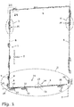
- FIG. 1 is a fitting 1 between a in FIG. 1 merely indicated wings 2 and a likewise only suggestively shown fixed frame 3 of a window 4 is provided.
- the fitting 1 is an espagnolette fitting whose wing-side fitting parts are accommodated in the usual manner in a fitting part groove which extends on the folding surface of the wing 2 in the wing circumferential direction.
- Assigned to the wing-side fitting parts of the fitting 1 are fixed-frame-side fitting parts which are arranged on the folding surface of the fixed frame 3 and are connected there to the fixed frame 3.
- wing-side espagnolette elements 6 of the fitting 1 are moved in the wing circumferential direction in a known manner. With the espagnolette elements 6 move fitting fittings that are thereby delivered relative to associated fixed frame side fitting parts. In this way, the fitting 1 in a in FIG. 1 and also in a tilt-open state and in a locked state.
- the lateral closing piece 9 is mounted on an opening-side vertical spar of the fixed frame 3 so that it can not be moved.
- Lower latch pins 10 on lower drive rod elements 6 are at the level of passage openings 11 which are provided on lower closing pieces 12 and which can be passed in the transverse direction of the main plane of the window 4 of the lower locking pin 10.
- the lower locking pins 10 are designed as a mushroom pin.
- Kippö Stamms Kunststoff of the fitting 1 the lower locking pins 10 are in itself along the tilting axis 16 extending and in FIG. 1 hinted recognizable longitudinal slots of the lower striker 12 run and now engage with their mushroom heads, the longitudinal edges of the guide slots on the lower strikers 12.
- the lower locking pins 10 are adjacent to a transversely extending the tilting axis 16 transverse boundary of the guide slots on the lower closing pieces 12 immediately adjacent.
- the circular tongue 17 of the circular tongue arrangement 13, which dips into the circular-tongue engagement 15, is in the immediate vicinity of an in FIG.
- the lower closing pieces 12 of the fitting 1 assume the function of tilting bearings for the wing 2.
- Intermediate elements in the form of lateral stop pieces 19 are arranged in the rebate spaces between the vertical beams of the wing 2 and the opposite vertical beams of the fixed frame 3 and provide a guide of the wing 2 in its pivotal movement about the tilting axis sixteenth
- the opening width of the tilted in the tilted opening position wing 2 is limited by two Kippö Stammsvortechniken 20 which are provided on the transverse in the transverse direction of the tilting axis 16 extending vertical beams of the wing 2 and the fixed frame 3 kippachsfern ( FIG. 1 ).
- each of the Kippö Stammsvortechnischen 20 includes a fixed frame side securing arm 21 and a wing-side coupling element in the form of a wing-side coupling pin 22 (FIG. Figures 4b, 4c ).
- the safety arm 21 is pivotally mounted on a mounting part 23.
- the mounting part 23 is bolted to the fixed frame 3 at the folding surface and also serves as a closing piece.
- the mounting member 23 is provided with a longitudinal slot 24 ( FIG. 3 ), whose longitudinal edges are undercut and in the locked state of the fitting 1 can be engaged behind by a mushroom head of the coupling pin 22. To get one in FIG.
- a guide slot 26 which serves to guide the wing-side coupling pin 22 and having undercut longitudinal edges.
- the longitudinal edges of the guide slot 26 can be engaged behind by the mushroom head of the coupling pin 22 designed as a mushroom pin.
- a shaft of the coupling pin 22 passes through an engagement opening 27 of the guide slot 26.
- FIG. 3 shows the unit of securing arm 21 and mounting member 23 in the view of that side, which faces in the installation position of the Kippö Stammsbegrenzungsvorraum 20 of the provided with the coupling pin 22 rebate surface of the wing 2.
- FIGS. 4a . 4b, 4c is the unit of securing arm 21 and mounting part 23 in the view of the viewer of FIG. 3 depicting the rear side of the arrangement. A lying towards the viewer groove base 30 of the guide slot 26 on the securing arm 21 is omitted for the sake of clarity.
- FIG. 4b shows the entire Kippö Stammsbegrenzungsvortechnisch 20 with the wing closed and 2 in the rotational opening state of the fitting 1.
- the securing arm 21 takes over the mounting part 23 its basic position in which it extends in the vertical direction.
- the attached to a wing-side espagnolette 6 coupling pin 22 is within a By rotation of the wing 2 about the vertical axis of rotation 7 of the wing 2 mitbewegte coupling pin 22 unhindered in the transverse direction of the main plane of the window 4 in the Recess recess 28 or leave the recess 28.
- FIGS. 4a . 4b, 4c the securing arm 21 is shown in the view on its space outside. There, the guide slot 26 of the securing arm 21 is covered by the sake of clarity, transparent groove bottom 30 shown.
- the swung in the tilted opening position wing 2 is particularly secure against burglary.
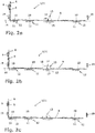
- FIG. 2a, 2b and 2c A special burglar security effect on the one hand in the Figures 2a, 2b and 2c shown in detail on the lower cross members of the wing 2 and the fixed frame 3.
- the lower locking pin 10 as a securing pin, the lower strikers 12 and the circular tongues arrangement 13 jointly form a switchable displacement lock 31, which ensures that the tilt-open wing 2 only at best slightly relative to the fixed frame 3 along the tilting axis 16 can be moved. In this case, the wing 2 is secured along the tilting axis 16 in both directions.
- the circular tongue engagement 15 act as a fixed-frame-side securing element or as festrahmen butterer stop and the circular tongue 17 of the circular tongue assembly 13 as a wing-side fuse element or switchable wing-side counter-attack of the anti-displacement device 31 together when the wing 2 forcibly in FIG. 2b is acted upon to the left.
- the circular tongue engagement 15 and the circular tongue 17 are effective as a stop and counter-stop, but with greater play along the tilt axis sixteenth
- a lateral displacement of the wing 2 in FIG. 2b to the right also acts in FIG. 2b right lateral stop piece 19, a lateral displacement of the wing 2 in FIG. 2b to the left in FIG. 2b left lateral stop piece 19 against.
- the lower closing pieces 12 form abutments, which are engaged behind by the lower locking pins 10, in particular by their mushroom heads.
- the rear grip of the circular tongue 17 on the circular tongue engagement 15 counteracts a displacement of the wing 2 relative to the fixed frame 3 in the transverse direction of the tilting axis 16.
- the Kippö Stammsbegrenzungsvortechnischen 20 contribute to the increased security against burglary of the wing 2.
- InQuery is on the one hand the fact that provided on the tilt-open wing 2 coupling pin 22 of each Kippö Stammsbegrenzungsvorraum 20 with its mushroom head, the longitudinal edges of the guide slot 26 on the associated fixed frame side Locking arm 21 engages behind and thereby counteracts a displacement of the wing 2 relative to the fixed frame 3 along the tilting axis 16.
- the connection made between the securing arm 21 and the fixed frame 3 via the mounting part 23 along the tilting axis 16 is particularly resilient.
- FIG. 1 shows the (dashed lines) handle 5 while down.
- the lateral locking pin 8 is engaged in the lateral locking piece 9, the lower locking pins 10 have due to the rotational operation of the handle 5, starting from their positions according to FIG. 2b the passages 11 of the lower striker 12 passes along the tilting axis 16 and are now in Figure 2c on the left side of the passage openings 11, where they engage behind with their mushroom heads the longitudinal edges of corresponding longitudinal slots on the lower closing pieces 12.
- the Kreiszeptan extract 13 takes over in the illustrated example, no locking function.
- the coupling pins 22 are in the longitudinal slots 24 of acting as closing pieces mounting parts 23 run in the locked state of the fitting 1.
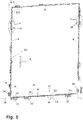
- FIG. 5 illustrated fitting 60 is correct in construction and operation largely with the fitting 1 according to FIG. 1 match. Modified relative to the fitting 1 is the switchable displacement lock 31 of the fitting 60.
- a Kreiszeptan extract 13 of in FIG. 1 shown type is not provided in the case of the fitting 60.
- a lateral displacement of the wing 2 relative to the fixed frame 3 act on the lower cross members of the wing 2 and the fixed frame 3 in tilt-open window 4 consequently only serve as wing-side securing elements lower locking pin 10 and the latter as fixed-frame-side securing elements associated lower strikers 12 of the fitting 60 against.
- the lower locking pins 10 and the lower strikers 12 of the safety securing device 31 of the fitting 60 jointly prevent unwanted displacement of the tilting wing 2 along the tilting axis 16 in FIG FIG. 5 to the right.
- switchable restraint 61 is provided at the location of the rotary tongue arrangement 1 according to FIG. 1 in the case of fitting no FIG. 5 strongly schematic and in FIG. 6 shown in detail switchable restraint 61 is provided.
- the retaining device 61 is identical in construction to the tilt-opening limiting devices 20 mounted on the window 4, which are tilt-remote.
- the retaining device 61 comprises a wing-side retaining element in the form of a retaining pin 62 and a retaining frame 63 on the fixed frame side.
- the retaining pin 62 is formed as a mushroom pin and attached to the displaceable along the lower transverse spar of the wing 2 espagnolette element 6, wherein the retaining pin 62 projects perpendicular to the rebate surface of the lower wing crossbar to the retaining arm 63 out.
- the retaining arm 63 is rotatably supported about a pivot axis 65 on a bearing part 64 corresponding to the mounting part 23 of the tilt-opening limiting device 20.
- the bearing member 64 is bolted to the lower cross member of the fixed frame 3 fixed to the folding surface.
- fastening screws safety screws of conventional design, not shown here, are used for the sake of simplicity.
- the axis of rotation 65 of the retaining arm 63 is perpendicular to the tilting axis 16 and parallel to the main plane of the window 4.
- the bearing member 64 also acts as a closing piece and is for this purpose with a longitudinal slot 66 with undercut longitudinal edges Mistake.
- the undercut longitudinal edges of the longitudinal slot 66 on the bearing part 64 can be engaged behind by a pin head 67, to which a pin shaft 68 of the retaining pin 62 is radially expanded.
- the retaining device 61 of the fitting 60 can be switched by rotary actuation of the handle 5 in different functional states.
- the wing-side retaining pin 62 in the in FIG. 6 shown in solid lines in an inlet 72 between the bearing part 64 and the retaining arm 63 of the retaining device 61. Due to its arrangement, the retaining pin 62 allows a rotational movement of the wing 2 about the vertical axis of rotation 7.
- the fitting 60 is switched from its rotational opening state into the tilt-open state while the wing 2 is still closed, and the handle 5 is rotated counterclockwise by 90 ° for this purpose from its horizontal orientation, the retaining pin 62 moves along the retaining arm 63 in FIG FIG. 6 to the right in the position immediately adjacent to its starting position, which in FIG. 6 is indicated by dashed lines on the right side of the retaining pin 62 shown in solid lines. Thereby, the retaining pin 62 is engaged with the guide slot 69 on the retaining arm 63. The retaining device 61 of the fitting 60 is thus in the retention standby state. In the restraint standby state, the restraint device 61 allows tilting movements of the wing 2 relative to the fixed frame 3.
- the restraint-ready state of the restraint 61 is assigned the tilt-open state of the bracket 60. Accordingly, the lower latch pins 10 are engaged along the tilting axis 16 in the lower strikers 12. In cooperation with the lower strikers 12, the lower latch pins 10 engaged in them secure the wing 2 against undesired displacement FIG. 5 to the right.
- the wing 2 Against a displacement perpendicular to the tilting axis 16 upwards, the wing 2 is secured to the fixed frame 3, since the lower locking pins 10 with their mushroom heads engage behind the longitudinal edges of the guide slots provided on the lower closing pieces 12 for the lower locking pins 10. And also perpendicular to the main plane of the window 4, the lower locking pins 10 in cooperation with the lower closing pieces 12 of the fitting located in Kippö Stammsschreib 60 cause a support of the wing 2 on the fixed frame. 3
- the retaining pin 62 of the retaining device 61 moves from its wooachsnahen position while pivoting the retaining arm 63 about the axis of rotation 65 along the retaining arm 63, until the retaining pin 62 abuts the transverse wall 70 of the guide slot 69.
- the retaining pin 62 is in FIG. 6 shown in dashed outline on the right.
- the transverse wall 70 of the retaining arm 63 prevents the now wooachsfern arranged retaining pin 62 a further violent Abstellterrorism of the retaining pin provided with the wing 2 with respect to the fixed frame.
- the restraint device 61 provides burglary protection of the type described above in detail for the tilt-opening limiting devices 20.
Description
Die Erfindung betrifft einen Beschlag zum Einbau zwischen einem Flügel und einem festen Rahmen, die als Bauelemente eines Fensters, einer Tür oder dergleichen vorgesehen sind,
- wobei der Beschlag in einen als Öffnungszustand vorgesehenen Kippöffnungszustand schaltbar ist und im Kippöffnungszustand als Schwenkachse eine Kippachse definiert, um welche bei eingebautem Beschlag der Flügel relativ zu dem festen Rahmen in eine Öffnungsstellung in Form einer Kippöffnungsstellung und in eine Geschlossenstellung schwenkbar ist,
- wobei der Beschlag als Öffnungsbegrenzungsvorrichtung eine Kippöffnungsbegrenzungsvorrichtung umfasst, welche im eingebauten Zustand zwischen einem in Querrichtung der Kippachse verlaufenden Flügelholm und einem diesem gegenüberliegenden Holm des festen Rahmens vorgesehen ist und welche ein an dem einen der Bauelemente vorgesehenes Kupplungselement sowie einen an dem anderen der Bauelemente vorgesehenen Sicherungsarm umfasst, der um eine sich parallel zu der Kippachse erstreckende Drehachse drehbeweglich ist,
- wobei bei Kippöffnungszustand des Beschlags beim Schwenken des Flügels um die Kippachse das Kupplungselement der Kippöffnungsbegrenzungsvorrichtung an dem Sicherungsarm der Kippöffnungsbegrenzungsvorrichtung in radialer Richtung der Drehachse des Sicherungsarms geführt und längs der Kippachse abgestützt ist,
- wobei bei Kippöffnungszustand des Beschlags das Kupplungselement der Kippöffnungsbegrenzungsvorrichtung bei Geschlossenstellung des Flügels nahe der Drehachse des Sicherungsarms und bei Kippöffnungsstellung des Flügels drehachsfern angeordnet ist und
- wobei die Kippöffnungsbegrenzungsvorrichtung für das drehachsfern angeordnete Kupplungselement einen Bewegungsbegrenzer aufweist, durch welchen das drehachsfern angeordnete Kupplungselement bei Kippöffnungsstellung des Flügels an einer von der Drehachse des Sicherungsarms weg gerichteten Bewegung gehindert und dadurch eine maximale Kippöffnungsweite des Flügels definiert ist.
- wherein the fitting is switchable to a Kippöffnungszustand provided as an opening state and in Kippöffnungszustand defined as a pivot axis a tilting axis about which is hinged with built-in fitting of the wings relative to the fixed frame in an open position in the form of a Kippöffnungsstellung and in a closed position,
- wherein the fitting as the opening limiting device comprises a Kippöffnungsbegrenzungsvorrichtung which is provided in the installed state between a transverse to the tilt axis extending wing spar and this opposite rail of the fixed frame and which provided on the one of the components coupling element and provided on the other of the components securing arm comprising, which is rotatable about an axis of rotation extending parallel to the tilt axis,
- wherein in Kippöffnungszustand the fitting when pivoting the wing about the tilt axis, the coupling element of Kippöffnungsbegrenzungsvorrichtung is guided on the securing arm of Kippöffnungsbegrenzungsvorrichtung in the radial direction of the axis of rotation of the securing arm and supported along the tilt axis,
- wherein at Kippöffnungszustand the fitting, the coupling element of the tilting opening limiting device is arranged in the closed position of the wing near the axis of rotation of the securing arm and at Kippöffnungsstellung the wing drehachsfern and
- wherein the Kippöffnungsbegrenzungsvorrichtung for the drehachsfern arranged coupling element has a movement limiter by which the drehachsfern arranged coupling element prevented in Kippöffnungsstellung the wing at a directed away from the axis of rotation of the securing arm movement and thereby a maximum Kippöffnungsweite the wing is defined.
Die Erfindung betrifft des Weiteren ein Fenster, eine Tür oder dergleichen mit einem Beschlag der vorstehenden Art.The invention further relates to a window, a door or the like with a fitting of the above type.
Gattungsgemäßer Stand der Technik ist bekannt aus
Weiterer Stand der Technik ist bekannt aus
Die Aufgabe der vorliegenden Erfindung besteht ausgehend von dem gattungsgemäßen Stand der Technik darin, einen Beschlag bereitzustellen, der eine hohe Einbruchssicherheit eines mit einer definierten Öffnungsweite kippbaren Flügels eines Fensters, einer Tür oder dergleichen gewährleistet.The object of the present invention, starting from the generic state of the art, is to provide a fitting which ensures a high burglar resistance of a wing of a window, a door or the like which can be tilted with a defined opening width.
Erfindungsgemäß gelöst wird diese Aufgabe durch den Beschlag gemäß Patentanspruch 1 und durch das Fenster, die Tür oder dergleichen gemäß Patentanspruch 17.This object is achieved according to the invention by the fitting according to
Die anspruchsgemäße Kippöffnungsbegrenzungsvorrichtung umfasst einen Sicherungsarm, der vorzugsweise an dem festen Rahmen um eine parallel zu der Kippachse des Flügels verlaufende Drehachse drehbar gelagert ist und außerdem ein Kupplungselement, das vorzugsweise an dem Flügel vorgesehen ist. Dabei sind der Sicherungsarm und das Kupplungselement insbesondere an einer Falzfläche des festen Rahmens und an einer Falzfläche des Flügels montiert, die bei Geschlossenstellung des Flügels der Falzfläche des festen Rahmens gegenüberliegt. Wenn die Kippachse des Flügels horizontal verläuft, erstrecken sich der Flügelholm und der Holm des festen Rahmens, zwischen denen die Kippöffnungsbegrenzungsvorrichtung vorgesehen ist, in vertikaler Richtung. Parallel zu der Kippachse sind das Kupplungselement und der Sicherungsarm der Kippöffnungsbegrenzungsvorrichtung aneinander abgestützt.The claimed Kippöffnungsbegrenzungsvorrichtung comprises a securing arm, which is preferably rotatably mounted on the fixed frame about an axis of rotation parallel to the tilt axis of the wing and also a coupling element, which is preferably provided on the wing. In this case, the securing arm and the coupling element are mounted in particular on a rebate surface of the fixed frame and on a rebate surface of the wing, which is opposite in the closed position of the wing of the rebate surface of the fixed frame. When the tilting axis of the wing is horizontal, the wing spar and the spar of the fixed frame, between which the tilting opening limiting device is provided, extend in the vertical direction. Parallel to the tilting axis, the coupling element and the securing arm of the tilting opening limiting device are supported against each other.
Die Gefahr, dass sich beispielsweise Einbrecher Zugang zu mit einem Fenster, einer Tür oder dergleichen versehenen Räumlichkeiten verschaffen wollen, besteht insbesondere bei kippgeöffnetem Flügel. Ziel des Einbrechers ist es, den Flügel über die Kippöffnungsweite hinaus von dem festen Rahmen weg zu bewegen. Zu diesem Zweck werden auf einen kippgeöffneten Flügel erfahrungsgemäß Kräfte sowohl senkrecht als auch parallel zu der Hauptebene des betreffenden Fensters, der betreffenden Tür oder dergleichen ausgeübt.The risk that, for example, burglars want to gain access to provided with a window, a door or the like premises, exists in particular with tilt-open wing. The goal of the burglar is to move the wing away from the fixed frame beyond the tipping opening width. For this purpose, according to experience, forces acting both vertically and parallel to the main plane of the relevant window, door or the like are exerted on a tilt-open wing.
Senkrecht zu der Hauptebene des betreffenden Fensters, der betreffenden Tür oder dergleichen kann der Flügel durch einen Einbrecher beispielsweise im Bereich der Kippachse beaufschlagt werden. Durch Aufhebeln des Flügels will der Einbrecher den Flügel kippachsseitig von dem festen Rahmen trennen. Einer derartigen Trennung des Flügels von dem festen Rahmen wirkt die erfindungsgemäße, bei kippgeöffnetem Flügel in einen Rückhaltebereitschaftszustand geschaltete Rückhaltevorrichtung gemäß Patentanspruch 1 entgegen. Wird der kippgeöffnete Flügel kippachsseitig mit Gewalt senkrecht zu der Hauptebene des betreffenden Fensters, der betreffenden Tür oder dergleichen von dem festen Rahmen abgehoben, so bewegt sich das Rückhalteelement der Rückhaltevorrichtung längs des Rückhaltearms der Rückhaltevorrichtung, wobei der Rückhaltearm infolge der relativ zu dem festen Rahmen ausgeführten Bewegung des Flügels um seine Drehachse geschwenkt wird. Die Bewegung des Rückhalteelements längs des Rückhaltearms und somit die von dem festen Rahmen weg gerichtete Bewegung des Flügels endet, sobald der Rückhalter der Rückhaltevorrichtung wirksam wird und eine fortgesetzte Bewegung des Rückhalteelements längs des Rückhaltearms verhindert. Bei zweckentsprechender Bemessung der Länge des Rückhaltearms besitzt der Flügel bei Ansprechen der erfindungsgemäßen Rückhaltevorrichtung einen Abstand von dem festen Rahmen, der zu klein ist, als dass ein Einbrecher durch den Spalt zwischen dem Flügel und dem festen Rahmen in die betreffenden Räumlichkeiten eindringen könnte. Der kippachsseitig von dem festen Rahmen gewaltsam getrennte Flügel bleibt sowohl über die Rückhaltevorrichtung als auch über die Kippöffnungsbegrenzungsvorrichtung, die gleichfalls einbruchsichernde Eigenschaften besitzt, an den festen Rahmen angebunden.Perpendicular to the main plane of the relevant window, the relevant door or the like, the wing can be acted upon by a burglar, for example in the region of the tilt axis. By levering the wing of the burglar wants to separate the wing kippachsseit of the fixed frame. Such a separation of the sash from the fixed frame is counteracted by the retention device according to the invention, which, when the sash is opened in a retention standby state, is in accordance with
Der erfindungsgemäße Beschlag gemäß Patentanspruch 1 sowie das mit dem erfindungsgemäßen Beschlag versehene Fenster, die damit versehene Tür oder dergleichen gemäß Patentanspruch 17 zeichnen sich folglich durch eine hohe Einbruchsicherheit aus.The fitting according to the invention according to
Besondere Ausführungsarten der in den Patentansprüchen 1 und 17 beschriebenen Vorrichtungen ergeben sich aus den abhängigen Patentansprüchen 2 bis 16.Particular embodiments of the devices described in the
Ein Öffnen des kippgeöffneten Flügels über die mittels der Kippöffnungsbegrenzungsvorrichtung begrenzte Kippöffnungsweite hinaus ist möglich, indem die über den Sicherungsarm und das Kupplungselement der Kippöffnungsbegrenzungsvorrichtung hergestellte Verbindung zwischen dem festen Rahmen und dem Flügel gelöst wird. Ein Einbrecher kann zu diesem Zweck bestrebt sein, die längs der Kippachse des Flügels wirksame gegenseitige Abstützung des Sicherungsarms und des Kupplungselements der Kippöffnungsbegrenzungsvorrichtung aufzuheben. Dies ließe sich dadurch bewerkstelligen, dass der Flügel beispielsweise mittels eines hebelartigen Einbruchswerkzeugs längs der Kippachse relativ zu dem festen Rahmen verschoben wird. Einer derartigen Verlagerung des Flügels längs der Kippachse wirkt die erfindungsgemäße Verschiebesicherung gemäß Patentanspruch 2 entgegen. Ist die erfindungsgemäße Verschiebesicherung in den Sicherungszustand geschaltet, so wird durch die miteinander zusammenwirkenden Sicherungselemente der Verschiebesicherung die Beweglichkeit des Flügels relativ zu dem festen Rahmen längs der Kippachse zumindest begrenzt. Insbesondere werden Bewegungen des Flügels längs der Kippachse durch die Verschiebesicherung und deren Sicherungselemente gänzlich verhindert.Opening the tilt-open wing beyond the tilt opening width limited by the tilt-opening limiting device is possible by releasing the connection between the fixed frame and the wing made via the securing arm and the coupling element of the tilt-opening limiting device. A burglar may be endeavored for this purpose to cancel the effective along the tilt axis of the wing mutual support of the securing arm and the coupling element of Kippöffnungsbegrenzungsvorrichtung. This could be accomplished by moving the wing relative to, for example, a lever-type burglary tool along the tilting axis is moved to the fixed frame. Such displacement of the wing along the tilt axis counteracts the anti-displacement device according to
Gemäß Patentanspruch 2 ist in vorteilhafter Ausgestaltung der Erfindung ein Beschlag vorgesehen, der sowohl mit einer schaltbaren Rückhaltevorrichtung gemäß Patentanspruch 1 als auch mit einer schaltbaren Verschiebesicherung ausgerüstet ist.According to
Patentanspruch 3 betrifft eine besonders einbruchsichere Bauart des erfindungsgemäßen Beschlags. Das Rückhalteelement der Rückhaltevorrichtung ist als Pilzkopfzapfen ausgeführt, der an dem Rückhaltearm der Rückhaltevorrichtung in einen Führungsschlitz mit hinterschnittenen Längsrändern eingreift.Claim 3 relates to a particularly burglar-proof design of the fitting according to the invention. The retaining element of the retaining device is designed as a mushroom pin, which engages the retaining arm of the retaining device in a guide slot with undercut longitudinal edges.
Ausweislich Patentanspruch 4 ist in Weiterbildung des erfindungsgemäßen Beschlags für die Rückhaltevorrichtung ein Rückhaltearm mit einem Führungsschlitz vorgesehen, der nach Art einer Führungsnut einen Nutboden aufweist. Der Nutboden deckt den Bereich der Führung des Rückhalteelements an dem Rückhaltearm der Rückhaltevorrichtung nach außen hin ab. Dadurch wird der Bereich der gegenseitigen Abstützung von Rückhalteelement und Rückhaltearm beispielsweise gegen Verschmutzung aber auch gegen einen unbefugten Zugriff von außen geschützt.As shown in claim 4, a restraining arm is provided with a guide slot in a further development of the fitting according to the invention for the restraint, which has a groove bottom in the manner of a guide groove. The groove bottom covers the region of the guidance of the retaining element on the retaining arm of the retaining device to the outside. As a result, the area of mutual support of retaining element and retaining arm is protected against contamination, for example, but also against unauthorized access from the outside.
In weiterer bevorzugter Ausgestaltung des erfindungsgemäßen Beschlags wird das Rückhalteelement der Rückhaltevorrichtung auch genutzt, um bei regulären Verhältnissen den Flügel an dem festen Rahmen zu verriegeln (Patentanspruch 5).In a further preferred embodiment of the fitting according to the invention, the retaining element of the retaining device is also used to lock the wing at the fixed frame at regular conditions (claim 5).
Vorteilhafterweise kann dabei das Schließstück mit dem Rückhaltearm der Rückhaltevorrichtung eine Baueinheit bilden und zu diesem Zweck den Rückhaltearm drehbar lagern (Patentanspruch 6).Advantageously, while the closing piece with the retaining arm of the retaining device form a structural unit and rotatably support the retaining arm for this purpose (claim 6).
Eine besonders belastbare Anbindung des Schließstücks an das zugeordnete Bauelement ergibt sich, wenn das Schließstück unabhängig von dem Rückhaltearm mit dem zugeordneten Bauelement verbindbar ist (Patentanspruch 7). Ist der Rückhaltearm an dem Schließstück angelenkt und ist die zwischen dem Schließstück und dem Rückhaltearm zu diesem Zweck hergestellte Verbindung entsprechend lastaufnahmefähig, so ist auch die Anbindung des Rückhaltearms an das mit dem Schließstück versehene Bauelement besonders belastbar und folglich einbruchsicher.A particularly strong connection of the striker to the associated component results when the striker is connected independently of the retaining arm with the associated component (claim 7). If the restraint arm is articulated on the closing piece and if the connection produced between the closing piece and the restraining arm for this purpose is load-bearing-capable, the connection of the restraining arm to the component provided with the closing piece is also particularly load-bearing and consequently burglar-proof.
Im Interesse einer besonders hohen Einbruchsicherheit ist im Falle der Erfindung außerdem vorgesehen, dass das Schließstück, in welches das Rückhalteelement der Rückhaltevorrichtung bei Verriegelungszustand des Beschlags eingreift und an welchem in bevorzugter Ausgestaltung der Erfindung der Rückhaltearm der Rückhaltevorrichtung drehbar gelagert ist, mittels wenigstens einer Sicherheitsschraube mit dem zugeordneten Bauelement verschraubbar ist (Patentanspruch 8). Alle gängigen Bauarten von Sicherheitsschrauben kommen dabei in Frage, wie etwa Schrauben mit Sicherheitseinsatz, Abreißschrauben oder Einwegschrauben, die mit herkömmlichen Hilfsmitteln nur in Anzugsrichtung gedreht werden können.In the interest of a particularly high security against burglary is also provided in the case of the invention that the closing piece, in which engages the retaining element of the retaining device in the locked state of the fitting and on which in a preferred embodiment of the invention, the retaining arm of the retaining device is rotatably supported by means of at least one security screw the associated component can be screwed (claim 8). All common types of security screws come into question, such as screws with safety insert, tear-off screws or disposable screws, which can be rotated with conventional tools only in the tightening direction.
Gemäß Patentanspruch 9 ist in bevorzugter Ausgestaltung der Erfindung vorgesehen, dass der dem kippgeöffneten Flügel zugeordnete Rückhaltebereitschaftszustand der erfindungsgemäßen Rückhaltevorrichtung dadurch hergestellt wird, dass das Rückhalteelement und/oder der Rückhaltearm der Rückhaltevorrichtung in eine Rückhaltebereitschaftsposition bewegt wird beziehungsweise werden, von der ausgehend die Rückhaltevorrichtung ansprechen kann, wenn der Flügel eine irreguläre kippachsseitige Bewegung gegenüber dem festen Rahmen ausführt. Die Überführung der Rückhaltevorrichtung in den Rückhaltebereitschaftszustand lässt sich infolgedessen ohne Weiteres in die Funktionalität üblicher Fenster- oder Türbeschläge integrieren und beispielsweise mittels Treibstangenantrieben realisieren.According to
Kippöffnungsbegrenzungsvorrichtungen der in dem Oberbegriff von Patentanspruch 1 angegebenen Art sind aufgrund ihrer konstruktiven Merkmale grundsätzlich in der Lage als erfindungsgemäße Rückhaltevorrichtungen zu fungieren. Diesem Umstand trägt die Erfindungsbauart gemäß Patentanspruch 10 Rechnung. Für den Beschlagverarbeiter bietet sich die Möglichkeit, zur Reduzierung seines Lagerbestandes ein und dieselbe Vorrichtung für unterschiedliche Anwendungen vorzuhalten. Außerdem vereinheitlicht sich die Beschlagteilmontage.Kippöffnungsbegrenzungsvorrichtungen specified in the preamble of
Im Falle der Erfindungsbauart gemäß Patentanspruch 11 wird der Rückhaltebereitschaftszustand der Rückhaltevorrichtung und/oder der Sicherungszustand der Verschiebesicherung zwangsläufig durch Überführen des Beschlags aus einem weiteren Funktionszustand in den Kippöffnungszustand hergestellt. Gesonderter Maßnahmen zum Umschalten der in einem Außerfunktionszustand befindlichen Rückhaltevorrichtung und/oder der in einem Außerfunktionszustand befindlichen Verschiebesicherung in den Funktionszustand bedarf es dementsprechend nicht. In weiterer bevorzugter Ausgestaltung der Erfindung ist vorgesehen, dass die in den Sicherungszustand geschaltete Verschiebesicherung die Beweglichkeit des Flügels relativ zu dem festen Rahmen längs der Kippachse in beiden Richtungen begrenzt bzw. gänzlich unterbindet.In the case of the invention type according to
Gemäß Patentanspruch 12 wird der Sicherungszustand der Verschiebesicherung herbeigeführt, indem das flügelseitige Sicherungselement und/oder das festrahmenseitige Sicherungselement der Verschiebesicherung längs der Kippachse in eine Sicherungsstellung bewegt wird bzw. werden. Das Umschalten der Verschiebesicherung in den Sicherungszustand lässt sich infolgedessen ohne Weiteres in die Funktionalität üblicher Fenster- oder Türbeschläge integrieren. Zur Bewegung des flügelseitigen Sicherungselements und/oder des festrahmenseitigen Sicherungselements in die Sicherungsstellung kann insbesondere eine Treibstange des Beschlages genutzt werden, die außerdem dazu dienen kann, Verriegelungselemente zum Ver- und Entriegeln des Flügels an dem festen Rahmen in und außer Eingriff zu bringen.According to
Mit konstruktiv einfachen Mitteln lässt sich die erfindungsgemäße Verschiebesicherung realisieren, wenn als festrahmenseitiges Sicherungselement ein festrahmenseitiger Anschlag und als flügelseitiges Sicherungselement ein dem festrahmenseitigen Anschlag zugeordneter flügelseitiger Gegenanschlag vorgesehen sind. Bei Sicherungszustand der Verschiebesicherung begrenzt beziehungsweise unterbindet der festrahmenseitige Anschlag im Zusammenwirken mit dem flügelseitigen Gegenanschlag Bewegungen des Flügels relativ zu dem festen Rahmen längs der Kippachse.With structurally simple means, the anti-displacement device according to the invention can be realized when a festrahmenseitiger stop and as wing-side securing element a fixed-frame-side stop associated wing-side counter-stop are provided as a fixed-frame side fuse element. In the securing state of the anti-displacement device, the stop on the fixed frame side limits, in cooperation with the anti-roll-side stop, movements of the blade relative to the fixed frame along the tilting axis.
In weiterer bevorzugter Ausgestaltung der Erfindung können als flügelseitige Gegenanschläge Beschlagteile vorgesehen sein, die alternativ als Riegelzapfen verwendet werden können.In a further preferred embodiment of the invention can be provided as wing-side counter-attacks fitting parts that can be used alternatively as a locking pin.
Durch die Mehrfachnutzung ein und desselben Beschlagteils vereinfacht sich die Vorratshaltung beim Beschlagverarbeiter. Die Beschlagteilmontage kann vereinheitlicht werden. Für die Beschlagteilmontage vorgesehene maschinelle Einrichtungen können sowohl zum Montieren von Verriegelungselementen als auch zum Montieren von Sicherungselementen der erfindungsgemäßen Verschiebesicherung eingesetzt werden.Due to the multiple use of one and the same fitting part, stockpiling at the fittings processor is simplified. The fittings assembly can be standardized. For the fitting part assembly provided mechanical devices can be used both for mounting of locking elements and for mounting fuse elements of the anti-displacement device according to the invention.
Durch eine besonders hohe Einbruchsicherheit zeichnet sich der erfindungsgemäße Beschlag gemäß Patentanspruch 13 aus. Im Falle dieses Beschlags ist die Beweglichkeit des Flügels relativ zu dem festen Rahmen vorzugsweise mittels Bauteilen der Verschiebesicherung nicht nur längs der Kippachse sondern auch in Querrichtung der Kippachse begrenzt bzw. gänzlich unterbunden.By a particularly high security against burglary, the fitting according to the invention is characterized according to
In bevorzugter Ausgestaltung der Erfindung ist zu diesem Zweck vorgesehen, dass das oder die flügelseitigen Sicherungselemente der Verschiebesicherung bei Sicherungszustand der Verschiebesicherung ein festrahmenseitiges und in Querrichtung der Kippachse wirksames Widerlager hintergreift oder hintergreifen (Patentanspruch 14).In a preferred embodiment of the invention, it is provided for this purpose that the one or more wing-side securing elements of the anti-slip device in backup state of the anti-slip device engages or engages behind a festrahmenseitiges and in the transverse direction of the tilting axis abutment (claim 14).
Im Falle einer erfindungsgemäßen Beschlagbauart, die als flügelseitigen Gegenanschlag einen Sicherungszapfen aufweist, ist zur Festlegung des Flügels in Querrichtung der Kippachse ein Sicherungszapfen mit einem in radialer Richtung einer Zapfenachse erweiterten Zapfenkopf vorgesehen, welcher das festrahmenseitige Widerlager mit dem Zapfenkopf hintergreift. Insbesondere ein derartiger Sicherungszapfen kann alternativ als Riegelzapfen (Pilzkopfzapfen) genutzt werden.In the case of a fitting design according to the invention, which has a securing pin as a wing-side counter-stop, is for fixing the wing in the transverse direction the tilting axis provided a securing pin with an enlarged in the radial direction of a pin axis pin head, which engages behind the fixed-frame-side abutment with the pin head. In particular, such a securing pin can alternatively be used as a locking pin (mushroom pin).
Ist als flügelseitiges Sicherungselement ein flügelseitiger Gegenanschlag vorgesehen, der zur Überführung der Verschiebesicherung in den Sicherungszustand in Querrichtung der Kippachse in die Sicherungsstellung bewegt wird, so muss die Bewegung des flügelseitigen Gegenanschlags zur Herstellung des Hintergriffs an einem in Querrichtung der Kippachse wirksamen Widerlager zusätzlich zu einer Komponente in Querrichtung der Kippachse eine Komponente längs der Kippachse aufweisen.If a wing-side counter-stop is provided as the wing-side securing element, which is moved to the securing position in the securing state in the transverse direction of the tilting axis in the securing position, the movement of the wing-side counter-attack for the production of the rear handle on an abutment effective in the transverse direction of the tilt axis abutment in addition to a component have a component along the tilting axis in the transverse direction of the tilting axis.
Ein derartiger flügelseitiger Gegenanschlag stimmt hinsichtlich seiner Kinematik mit Kreiszungen überein, die als Verriegelungselemente zum Verriegeln eines Flügels an einem festen Rahmen gebräuchlich sind. In bevorzugter Ausgestaltung der Erfindung wird als flügelseitiger Gegenanschlag daher eine im Übrigen als Verriegelungselement nutzbare Kreiszunge verwendet.Such a wing-side counter-stop coincides in terms of its kinematics with circular tongues, which are common as locking elements for locking a wing to a fixed frame. In a preferred embodiment of the invention is therefore used as a wing-side counter-attack usable in the rest as a locking element circular tongue.
Zur Vereinfachung der Beschlagteilmontage sind in Weiterbildung der Erfindung das festrahmenseitige Sicherungselement der längs der Kippachse wirksamen Verschiebesicherung und das in Querrichtung der Kippachse wirksame festrahmenseitige Widerlager für das flügelseitige Sicherungselement als Baueinheit ausgeführt (Patentanspruch 15).To simplify the fitting part mounting the fixed-frame-side securing element of the effective along the tilt axis shift protection and effective in the transverse direction of the tilt axis fixed frame side abutment for the wing-side fuse element as a unit executed in the invention (claim 15).
Derartige Baueinheiten sind in Form von herkömmlichen Schließstücken zur Flügelverriegelung verfügbar. In bevorzugter Ausgestaltung der Erfindung wird daher ein derartiges Schließstück verwendet, um die Beweglichkeit des kippgeöffneten Flügels relativ zu dem festen Rahmen sowohl längs der Kippachse als auch in Querrichtung der Kippachse zumindest zu begrenzen.Such units are available in the form of conventional closing pieces for wing locking. In a preferred embodiment of the invention, therefore, such a closing piece is used to at least limit the mobility of the tilt-open wing relative to the fixed frame both along the tilting axis and in the transverse direction of the tilting axis.
Im Interesse besonderer Einbruchsicherheit des erfindungsgemäßen Beschlages ist die Baueinheit aus dem festrahmenseitigen Sicherungselement und dem festrahmenseitigen Widerlager in Weiterbildung der Erfindung mittels wenigstens einer vorzugsweise herkömmlichen Sicherheitsschraube mit dem festen Rahmen verschraubbar.In the interest of particular burglar resistance of the fitting according to the invention, the assembly of the fixed-frame-side fuse element and the fixed frame side Abutment screwed in a further development of the invention by means of at least one preferably conventional security screw with the fixed frame.
Im Falle der Erfindungsbauart gemäß Patentanspruch 16 sind zusätzlich zu der erfindungsgemäßen Verschiebesicherung weitere Vorkehrungen getroffen, um ein unbefugtes Verschieben des kippgeöffneten Flügels längs der Kippachse weitestmöglich zu verhindern. Im Einzelnen vorgesehen ist wenigstens ein Zwischenelement, das sich in einem zwischen einem vertikalen Flügelholm und dem diesem gegenüberliegenden festen Rahmen vorhandenen Zwischenraum, insbesondere in einem Falzspalt, längs der Kippachse erstreckt. Auch durch ein derartiges Zwischenelement wird die Beweglichkeit des Flügels relativ zu dem festen Rahmen längs der Kippachse zumindest eingeschränkt. Sind Zwischenelemente längs der Kippachse beidseits des Flügels vorgesehen, so werden unerwünschte Bewegungen des Flügels längs der Kippachse in beiden Richtungen zumindest teilweise unterbunden.In the case of Erfindungsbauart according to claim 16 further precautions are taken in addition to the anti-displacement device according to the invention to prevent unauthorized movement of the tilt-open wing along the tilt axis as far as possible. In detail, at least one intermediate element is provided which extends in a gap between a vertical wing spar and the fixed frame opposite thereto, in particular in a folding gap, along the tilting axis. Also by such an intermediate element, the mobility of the wing is at least limited relative to the fixed frame along the tilt axis. Are intermediate elements along the tilt axis provided on both sides of the wing, so unwanted movements of the wing along the tilt axis in both directions are at least partially prevented.
Zur Gewährleistung einer hohen Einbruchsicherheit an der Kippöffnungsbegrenzungsvorrichtung des erfindungsgemäßen Beschlages ist das Kupplungselement der Kippöffnungsbegrenzungsvorrichtung als Kupplungszapfen ausgeführt, der längs der Kippachse mit einem Pilzkopf in einen Führungsschlitz an dem Sicherungsarm der Kippöffnungsbegrenzungsvorrichtung eingreift und dabei mit dem Pilzkopf die Längsränder des Führungsschlitzes an dem Sicherungsarm hintergreift.To ensure a high security against burglary on Kippöffnungsbegrenzungsvorrichtung of the fitting according to the invention the coupling element of Kippöffnungsbegrenzungsvorrichtung is designed as a coupling pin which engages along the tilt axis with a mushroom head in a guide slot on the securing arm of Kippöffnungsbegrenzungsvorrichtung while the mushroom head engages behind the longitudinal edges of the guide slot on the securing arm.
Zur Gewährleistung einer hohen Einbruchsicherheit an der Kippöffnungsbegrenzungsvorrichtung des erfindungsgemäßen Beschlages wird außerdem der an dem Sicherungsarm der Kippöffnungsbegrenzungsvorrichtung zur Führung des Kupplungszapfens der Kippöffnungsbegrenzungsvorrichtung vorgesehene Führungsschlitz von einer Führungsnut gebildet, deren Nutboden zu einer Raumaußenseite des Sicherungsarms hin weist. Durch den geschlossenen Nutbodens ist der Bereich der gegenseitigen Abstützung des Kupplungszapfens und des Sicherungsarms der Kippöffnungsbegrenzungsvorrichtung zu der Raumaußenseite hin abgedeckt. Dadurch wird ein unbefugter Zugriff auf den Bereich der gegenseitigen Abstützung des Kupplungszapfens und des Sicherungsarms der Kippöffnungsbegrenzungsvorrichtung zumindest erschwert.To ensure a high security against burglary on Kippöffnungsbegrenzungsvorrichtung of the fitting according to the invention also provided on the securing arm of Kippöffnungsbegrenzungsvorrichtung for guiding the coupling pin of Kippöffnungsbegrenzungsvorrichtung guide slot is formed by a guide groove, the groove bottom facing a space outside of the securing arm out. By the closed groove bottom, the region of the mutual support of the coupling pin and the securing arm of the tilting opening limiting device is covered to the outside of the room. As a result, unauthorized access to the region of the mutual support of the coupling pin and the securing arm of the tilting opening limiting device is at least made more difficult.
An einem erfindungsgemäßen Beschlag mit einer Verriegelungsfunktion dient das Kupplungselement der Kippöffnungsbegrenzungsvorrichtung, beispielsweise ein als Kupplungselement vorgesehener Pilzkopfzapfen, zur Gewährleistung einer hohen Einbruchsicherheit an der Kippöffnungsbegrenzungsvorrichtung des erfindungsgemäßen Beschlages auch zur Verriegelung des Flügels an dem festen Rahmen. Dem Kupplungselement der Kippöffnungsbegrenzungsvorrichtung ist dabei an dem anderen Bauelement des Fensters, der Tür oder dergleichen ein Schließstück zugeordnet. Der Sicherungsarm der Kippöffnungsbegrenzungsvorrichtung ist vorzugsweise an diesem Schließstück drehbar gelagert. Eine besonders belastbare Verbindung zwischen dem Schließstück und dem mit dem Schließstück versehenen Bauelement des Fensters, der Tür oder dergleichen ergibt sich aufgrund des Umstands, dass das Schließstück unabhängig von dem Sicherungsarm der Kippöffnungsbegrenzungsvorrichtung mit dem betreffenden Bauelement verbunden ist. Aufgrund der besonderen Belastbarkeit der Verbindung zwischen dem Schließstück und dem diesem zugeordneten Bauelement ist bei entsprechend belastbarer Drehlagerung des Sicherungsarms der Kippöffnungsbegrenzungsvorrichtung an dem Schließstück die Anbindung des an dem Schließstück drehbar gelagerten Sicherungsarms an das mit dem Schließstück versehene Bauelement gleichfalls besonders lastaufnahmefähig.At a fitting according to the invention with a locking function, the coupling element of Kippöffnungsbegrenzungsvorrichtung, for example, provided as a coupling element mushroom head, to ensure high security against burglary on Kippöffnungsbegrenzungsvorrichtung of the invention also serves to lock the wing to the fixed frame. The coupling element of the Kippöffnungsbegrenzungsvorrichtung is assigned to the other component of the window, the door or the like, a closing piece. The securing arm of the tilting opening limiting device is preferably rotatably mounted on this closing piece. A particularly strong connection between the striker and the device provided with the closing piece of the window, the door or the like is due to the fact that the striker is connected to the relevant component independently of the securing arm of Kippöffnungsbegrenzungsvorrichtung. Due to the special resilience of the connection between the striker and the associated therewith component is in accordance with load bearing rotary bearing of the securing arm of Kippöffnungsbegrenzungsvorrichtung on the striker the connection of the locking piece rotatably mounted on the securing arm to the provided with the striker component also particularly load-receptive.
Nachfolgend wird die Erfindung anhand beispielhafter schematischer Darstellungen näher erläutert.The invention will be explained in more detail below with reference to exemplary schematic illustrations.
Es zeigen:
Figur 1- eine perspektivische Darstellung einer nicht erfindungsgemäßen Bauart eines Beschlags für ein Fenster bei Drehöffnungszustand des Beschlags,
- Figur 2a
- den Bereich II in
Figur 1 - Figur 2b
- die Anordnung gemäß
Figur 2a bei Kippöffnungszustand des Beschlags, - Figur 2c
- die Anordnung gemäß den
Figuren 2a, 2b bei Verriegelungszustand des Beschlags, - Figur 3
- einen Sicherungsarm einer in dem Bereich
V von Figur 1 angeordneten Kippöffnungsbegrenzungsvorrichtung des Beschlags gemäßFigur 1 , - Figur 4a
- den Sicherungsarm gemäß
Figur 3 mit seiner Ausrichtung bei geschlossenem Flügel, - Figur 4b
- die Kippöffnungsbegrenzungsvorrichtung des Beschlags gemäß
Figur 1 im eingebauten Zustand und bei Drehöffnungszustand des Beschlags, - Figur 4c
- die Anordnung gemäß
Figur 4b bei Kippöffnungszustand des Beschlags, Figur 5- eine perspektivische Darstellung eines erfindungsgemäßen Beschlags für ein Fenster bei Drehöffnungszustand des Beschlags und
Figur 6- eine schaltbare Rückhaltevorrichtung des Beschlags gemäß
Figur 5.
- FIG. 1
- a perspective view of a non-inventive design of a fitting for a window in Drehöffnungszustand the fitting,
- FIG. 2a
- the area II in
FIG. 1 in the plan view, - FIG. 2b
- the arrangement according to
FIG. 2a at Kippöffnungszustand the fitting, - Figure 2c
- the arrangement according to the
FIGS. 2a, 2b when the fitting is locked, - FIG. 3
- a safety arm in the area V of
FIG. 1 arranged Kippöffnungsbegrenzungsvorrichtung of the fitting according toFIG. 1 . - FIG. 4a
- the safety arm according to
FIG. 3 with its orientation with the wing closed, - FIG. 4b
- the Kippöffnungsbegrenzungsvorrichtung the fitting according to
FIG. 1 in the installed state and in Drehöffnungszustand the fitting, - Figure 4c
- the arrangement according to
FIG. 4b at Kippöffnungszustand the fitting, - FIG. 5
- a perspective view of a fitting according to the invention for a window in Drehöffnungszustand of the fitting and
- FIG. 6
- a switchable retaining device of the fitting according to FIG. 5.
Gemäß
Bei dem Beschlag 1 handelt es sich um einen Treibstangenbeschlag, dessen flügelseitige Beschlagteile in gewohnter Weise in einer Beschlagteilnut untergebracht sind, die an der Falzfläche des Flügels 2 in Flügelumfangsrichtung verläuft. Den flügelseitigen Beschlagteilen des Beschlags 1 zugeordnet sind festrahmenseitige Beschlagteile, die an der Falzfläche des festen Rahmens 3 angeordnet und dort mit dem festen Rahmen 3 verbunden sind.The
Durch Drehbetätigung eines Handgriffs 5 werden in bekannter Weise flügelseitige Treibstangenelemente 6 des Beschlags 1 in Flügelumfangsrichtung bewegt. Mit den Treibstangenelementen 6 bewegen sich daran befestige Beschlagteile, die dadurch relativ zu zugeordneten festrahmenseitigen Beschlagteilen zugestellt werden. Auf diese Art und Weise kann der Beschlag 1 in einen in
Bei Drehöffnungszustand des Beschlags 1 nimmt der Handgriff 5 die in
Die Verhältnisse, wie sie sich bei Drehöffnungszustand des Beschlags 1 im Bereich der unteren Querholme des Flügels 2 und des festen Rahmens 3 darstellen, ergeben sich aus
Ein seitlicher Riegelzapfen 8 an einem vertikalen Treibstangenelement 6, das seinerseits an einem öffnungsseitigen Vertikalholm des Flügels 2 in Flügelumfangsrichtung geführt wird, ist außerhalb eines seitlichen Schließstücks 9 angeordnet. Das seitliche Schließstück 9 ist an einem öffnungsseitigen Vertikalholm des festen Rahmens 3 ortsunveränderlich montiert. Untere Riegelzapfen 10 an unteren Treibstangenelementen 6 liegen auf Höhe von Durchtrittsöffnungen 11, die an unteren Schließstücken 12 vorgesehen sind und die in Querrichtung der Hauptebene des Fensters 4 von den unteren Riegelzapfen 10 passiert werden können.A
Während sich die unteren Treibstangenelemente 6 mit den daran angebrachten unteren Riegelzapfen 10 durch Drehbetätigung des Handgriffs 5 längs des unteren Flügelquerholms bewegen lassen, sind die unteren Schließstücke 12 an dem unteren Querholm des festen Rahmens 3 mittels herkömmlicher Sicherheitsschrauben (nicht dargestellt) ortsunveränderlich befestigt. Eine Kreiszungenanordnung 13 mit einem flügelseitigen Anordnungsteil 14 und einem festrahmenseitigen Kreiszungeneingriff 15 ist in
Soll der Flügel 2 gegenüber dem festen Rahmen 3 kippgeöffnet und dementsprechend um eine untere horizontal verlaufende Kippachse 16 geschwenkt werden, so ist der Handgriff 5 aus der in
Aufgrund der Drehbetätigung des Handgriffs 5 verlagert sich das vertikale Treibstangenelement 6 ausgehend von seiner Position gemäß
Ebenso wie der seitliche Riegelzapfen 8 sind auch die unteren Riegelzapfen 10 als Pilzkopfzapfen ausgeführt. Bei Kippöffnungszustand des Beschlags 1 sind die unteren Riegelzapfen 10 in sich längs der Kippachse 16 erstreckende und in
Wird der Flügel 2 um die Kippachse 16 aus der Geschlossenstellung in die Kippöffnungsstellung und/oder aus der Kippöffnungsstellung in die Geschlossenstellung geschwenkt, so übernehmen die unteren Schließstücke 12 des Beschlags 1 die Funktion von Kipplagern für den Flügel 2. Zwischenelemente in Form von seitlichen Anschlagstücken 19 sind in den Falzräumen zwischen den Vertikalholmen des Flügels 2 und den diesen gegenüberliegenden Vertikalholmen des festen Rahmens 3 angeordnet und sorgen für eine Führung des Flügels 2 bei dessen Schwenkbewegung um die Kippachse 16.If the
Die Öffnungsweite des in die Kippöffnungsstellung geschwenkten Flügels 2 wird durch zwei Kippöffnungsbegrenzungsvorrichtungen 20 begrenzt, die an den in Querrichtung der Kippachse 16 verlaufenden Vertikalholmen des Flügels 2 und des festen Rahmens 3 kippachsfern vorgesehen sind (
Der Aufbau und die Funktionsweise der Kippöffnungsbegrenzungsvorrichtungen 20 ergeben sich aus den
Demnach umfasst jede der Kippöffnungsbegrenzungsvorrichtungen 20 einen festrahmenseitigen Sicherungsarm 21 sowie ein flügelseitiges Kupplungselement in Form eines flügelseitigen Kupplungszapfens 22 (
In radialer Richtung der Drehachse 25 erstreckt sich an dem Sicherungsarm 21 ein Führungsschlitz 26, der zur Führung des flügelseitigen Kupplungszapfens 22 dient und der hinterschnittene Längsränder aufweist. Die Längsränder des Führungsschlitzes 26 können von dem Pilzkopf des als Pilzkopfzapfen ausgebildeten Kupplungszapfens 22 hintergriffen werden. Ein Schaft des Kupplungszapfens 22 durchsetzt dabei eine Eingriffsöffnung 27 des Führungsschlitzes 26.In the radial direction of the axis of
Mit der Ausrichtung gemäß
Wird der Beschlag 1 durch Drehbetätigung des Handgriffs 5 aus dem Drehöffnungszustand (
Wird nun der Flügel 2 um die Kippachse 16 in die Kippöffnungsstellung geschwenkt, so bewegt sich der Kupplungszapfen 22 innerhalb des Führungsschlitzes 26 von der Position gemäß
In den
Der in die Kippöffnungsstellung geschwenkte Flügel 2 ist in besonderem Maße gegen Einbruch gesichert.The swung in the tilted
Eine besondere Einbruchsicherheit bewirken zum einen die in den
Wird der Flügel 2 etwa mittels eines zwischen dem Flügel 2 und dem festen Rahmen 3 angesetzten hebelartigen Einbruchswerkzeugs längs der Kippachse 16 in
In entsprechender Weise wirken der Kreiszungeneingriff 15 als festrahmenseitiges Sicherungselement beziehungsweise als festrahmenseitiger Anschlag und die Kreiszunge 17 der Kreiszungenanordnung 13 als flügelseitiges Sicherungselement beziehungsweise als schaltbarer flügelseitiger Gegenanschlag der Verschiebesicherung 31 miteinander zusammen, wenn der Flügel 2 gewaltsam in
Einer seitlichen Verlagerung des Flügels 2 in
In Querrichtung der Kippachse 16 bilden die unteren Schließstücke 12 Widerlager aus, die von den unteren Riegelzapfen 10, im Einzelnen von deren Pilzköpfen, hintergriffen werden. In gleicher Weise wirkt der Hintergriff der Kreiszunge 17 an dem Kreiszungeneingriff 15 einer Verlagerung des Flügels 2 relativ zu dem festen Rahmen 3 in Querrichtung der Kippachse 16 entgegen.In the transverse direction of the tilting
Auch die Kippöffnungsbegrenzungsvorrichtungen 20 leisten einen Beitrag zu der erhöhten Einbruchsicherheit des Flügels 2. Insofern von Bedeutung ist zum einen der Umstand, dass der an dem kippgeöffneten Flügel 2 vorgesehene Kupplungszapfen 22 einer jeden Kippöffnungsbegrenzungsvorrichtung 20 mit seinem Pilzkopf die Längsränder des Führungsschlitzes 26 an dem zugeordneten festrahmenseitigen Sicherungsarm 21 hintergreift und dadurch einer Verlagerung des Flügels 2 relativ zu dem festen Rahmen 3 längs der Kippachse 16 entgegenwirkt. Dabei ist die über das Montageteil 23 hergestellte Verbindung zwischen dem Sicherungsarm 21 und dem festen Rahmen 3 längs der Kippachse 16 besonders belastbar.The
Dadurch wird verhindert, dass der Sicherungsarm 21 aufgrund einer Kraftbeaufschlagung des Flügels 2 längs der horizontalen Kippachse 16 von dem festen Rahmen 3 gelöst wird. Ein Verbiegen des Sicherungsarms 21 infolge der Kraftbeaufschlagung des Flügels 2 wird durch die massive Konstruktion des Sicherungsarms 21 zumindest in erheblichem Maße erschwert. Der Nutboden 30 des Führungsschlitzes 26 an dem Sicherungsarm 21 macht den Bereich des Eingriffs des Kupplungszapfens 22 in den Führungsschlitz 26 von der Raumaußenseite her unzugänglich und sichert den Bereich des Eingriffs des Kupplungszapfens 22 in den Führungsschlitz 26 dadurch gegen unerwünschte Manipulation.This prevents that the securing
Die Verhältnisse bei Verriegelungszustand des Beschlags 1 sind in
Auch ein in
Eine Kreiszungenanordnung 13 der in
An der Stelle der Kreiszungenanordnung 1 gemäß
Gemäß
Der Rückhaltezapfen 62 ist als Pilzkopfzapfen ausgebildet und an dem längs des unteren Querholms des Flügels 2 verschiebbaren Treibstangenelement 6 angebracht, wobei der Rückhaltezapfen 62 senkrecht zu der Falzfläche des unteren Flügelquerholms zu dem Rückhaltearm 63 hin vorsteht. Der Rückhaltearm 63 ist an einem dem Montageteil 23 der Kippöffnungsbegrenzungsvorrichtung 20 entsprechenden Lagerteil 64 um eine Drehachse 65 drehbar gelagert. Das Lagerteil 64 ist mit dem unteren Querholm des festen Rahmens 3 an dessen Falzfläche ortsfest verschraubt. Als Befestigungsschrauben werden dabei der Einfachheit halber nicht gezeigte Sicherheitsschrauben üblicher Bauart verwendet.The retaining
An dem mit dem festen Rahmen 3 verschraubten Lagerteil 64 verläuft die Drehachse 65 des Rückhaltearms 63 senkrecht zu der Kippachse 16 und parallel zu der Hauptebene des Fensters 4. Das Lagerteil 64 fungiert außerdem als Schließstück und ist zu diesem Zweck mit einem Längsschlitz 66 mit hinterschnittenen Längsrändern versehen. Die hinterschnittenen Längsränder des Längsschlitzes 66 an dem Lagerteil 64 können von einem Zapfenkopf 67 hintergriffen werden, zu welchem ein Zapfenschaft 68 des Rückhaltezapfens 62 radial erweitert ist.At the bolted to the fixed frame 3 bearing
Ebenfalls mit hinterschnittenen Längsrändern ist ein Führungsschlitz 69 versehen, der sich an dem Rückhaltearm 63 in dessen Längsrichtung erstreckt und der an seinem von der Drehachse 65 des Rückhaltearms 63 abliegenden Ende durch eine als Rückhalter dienende Querwand 70 begrenzt wird. Ein Nutgrund des als Führungsnut ausgebildeten Führungsschlitzes 69 liegt einer Eingriffsöffnung 71 des Führungsschlitzes 69 gegenüber und ist in
Aufgrund der Anbindung des Rückhaltezapfens 62 an das Treibstangenelement 6 kann die Rückhaltevorrichtung 61 des Beschlags 60 durch Drehbetätigung des Handgriffs 5 in unterschiedliche Funktionszustände geschaltet werden.Due to the connection of the retaining
Bei Geschlossenstellung des Flügels 2 und bei Drehöffnungszustand des Beschlags 60 und dementsprechend horizontal nach rechts weisendem Handgriff 5 befindet sich der flügelseitige Rückhaltezapfen 62 in der in
Wird der Beschlag 60 bei weiterhin geschlossenem Flügel 2 ausgehend von seinem Drehöffnungszustand in den Kippöffnungszustand geschaltet und der Handgriff 5 zu diesem Zweck ausgehend von seiner horizontalen Ausrichtung um 90° im Gegenuhrzeigersinn nach oben gedreht, so wandert der Rückhaltezapfen 62 längs des Rückhaltearms 63 in
Dem Rückhaltebereitschaftszustand der Rückhaltevorrichtung 61 ist der Kippöffnungszustand des Beschlags 60 zugeordnet. Dementsprechend sind die unteren Riegelzapfen 10 längs der Kippachse 16 in die unteren Schließstücke 12 eingerückt. Im Zusammenwirken mit den unteren Schließstücken 12 sichern die in diese eingerückten unteren Riegelzapfen 10 den Flügel 2 gegen eine unerwünschte Verlagerung in
Gegen eine Verlagerung senkrecht zu der Kippachse 16 nach oben ist der Flügel 2 an dem festen Rahmen 3 gesichert, da die unteren Riegelzapfen 10 mit ihren Pilzköpfen die Längsränder der an den unteren Schließstücken 12 für die unteren Riegelzapfen 10 vorgesehenen Führungsschlitze hintergreifen. Und auch senkrecht zu der Hauptebene des Fensters 4 bewirken die unteren Riegelzapfen 10 im Zusammenspiel mit den unteren Schließstücken 12 des im Kippöffnungszustand befindlichen Beschlags 60 eine Abstützung des Flügels 2 an dem festen Rahmen 3.Against a displacement perpendicular to the tilting
Bei Kippöffnungszustand des Beschlags 60 und dem damit verbundenen Rückhaltebereitschaftszustand der Rückhaltevorrichtung 61 nehmen der Rückhaltezapfen 62 und der Rückhaltearm 63 der Rückhaltevorrichtung 61 relativ zueinander eine Rückhaltebereitschaftsstellung ein.When Kippöffnungszustand of the fitting 60 and the associated retention standby state of the retaining
Wird bei diesem Funktionszustand des Beschlags 60 und bei insbesondere kippgeöffnetem Flügel 2 beispielsweise bei einem Einbruchsversuch auf den Flügel 2 kippachsseitig senkrecht zu der Hauptebene des Fensters 4 eine irreguläre raumauswärts gerichtete Kraft mit einem entsprechend großen Betrag ausgeübt, so wird unter der Krafteinwirkung die mittels der unteren Riegelzapfen 10 und der unteren Schließstücke 12 senkrecht zu der Hauptebene des Fensters 4 bewirkte Abstützung des Flügels 2 an dem festen Rahmen 3 gewaltsam aufgehoben. Gleichzeitig wird aber die dem Einbruchschutz dienende und zu diesem Zweck in den Rückhaltebereitschaftszustand geschaltete Rückhaltevorrichtung 61 wirksam.If in this functional state of the fitting 60 and in particular tilt-
Aufgrund der gewaltsam herbeigeführten und senkrecht zu der Hauptebene des Fensters 4 raumauswärts gerichteten kippachsseitigen Bewegung des Flügels 2 relativ zu dem festen Rahmen 3 bewegt sich der Rückhaltezapfen 62 der Rückhaltevorrichtung 61 ausgehend von seiner drehachsnahen Position unter Schwenken des Rückhaltearms 63 um die Drehachse 65 längs des Rückhaltearms 63, bis der Rückhaltezapfen 62 an der Querwand 70 des Führungsschlitzes 69 anschlägt. In der damit eingenommenen Position ist der Rückhaltezapfen 62 in
Darüber hinaus bietet die Rückhaltevorrichtung 61 einen Einbruchschutz der vorstehend für die Kippöffnungsbegrenzungsvorrichtungen 20 im Einzelnen beschriebenen Art.In addition, the
Claims (17)
- Fitting for installation between a sash (2) and a fixed frame (3), which are provided as components of a window (4), a door or the like,• the fitting being switchable into a tilted-open state provided as an open state and, in the tilted-open state, defining a tilt axis (16) as a pivot axis, about which tilt axis, when the fitting is installed, the sash (2) can be pivoted relative to the fixed frame (3) into an open position, in the form of a tilted-open position, and into a closed position,• the fitting comprising, as an opening-limiting device, a tilt-opening-limiting device (20) which is provided, in the installed state, between a sash spar extending in the transverse direction of the tilt axis (16) and a spar of the fixed frame (3) located opposite said sash spar, and which comprises a coupling element (22) provided on one of the components and a securing arm (21) provided on the other component, which arm can be moved so as to rotate about an axis of rotation (25) extending in parallel with the tilt axis (16),• a in the tilted-open state of the fitting, during the pivoting of the sash (2) about the tilt axis (16), the coupling element (22) of the tilt-opening-limiting device (20) being guided on the securing arm (21) of the tilt-opening-limiting device (20) in the radial direction of the axis of rotation (25) of the securing arm (21) and being supported along the tilt axis (16),• in the tilted-open state of the fitting, the coupling element (22) of tilt-opening-limiting device (20) being arranged close to the axis of rotation (25) of the securing arm (21) in the closed position of the sash (2) and remote from the axis of rotation in the tilted-open position of the sash (2), and• the tilt-opening-limiting device (20) having, for the coupling element (22) arranged remotely from the axis of rotation, a movement limiter (29) by means of which the coupling element (22) arranged remotely from the axis of rotation is prevented from moving away from the axis of rotation (25) of the securing arm (21) when the sash (2) is in the tilted-open position, and thus a maximum tilted-open width of the sash is defined,characterized in that the fitting comprises a switchable retaining device (61) which is provided, in the installed state, between a tilt-axis-side sash spar extending in parallel with the tilt axis (16) and a tilt-axis-side spar of the fixed frame (3) located opposite said sash spar, and comprises a retaining element (62) provided on one of the components and a retaining arm (63) provided on the other component, which arm is rotatable about an axis of rotation (65) that extends perpendicularly to the tilt axis (16) and in parallel with a main plane of the window (4), the door or the like,
in that, in the tilted-open state of the fitting and when the sash (2) is connected to the fixed frame (3) on the tilt-axis side, the retaining device (61) is switched into a retaining standby state in which the retaining element (62) and the retaining arm (63) are arranged relative to each other such that the retaining element (62) is arranged close to the axis of rotation (65) of the retaining arm (63),
in that, during a movement carried out by the sash (2) relative to the fixed frame (3) on the tilt-axis side perpendicularly to the main plane of the window (4), the door or the like, during which movement the sash (2) is removed from the fixed frame (3) on the tilt-axis side, the retaining element (62) is movably guided into a position remote from the axis of rotation in the radial direction of the axis of rotation (65) of the retaining arm (63),
and in that, when the sash (2) is removed from the fixed frame (3) on the tilt-axis side, the retaining element (62) arranged remotely from the axis of rotation is prevented from moving in a direction oriented away from the axis of rotation (65) of the retaining arm (63) by a retainer (70) of the retaining device (61), thereby limiting the movability of the sash (2) relative to the fixed frame (3) on the tilt-axis side. - Fitting according to claim 1, characterized in that
the fitting comprises a switchable anti-displacement means (31) which is provided, in the installed state, between a tilt-axis-side sash spar extending in parallel with the tilt axis (16) and a tilt-axis-side spar of the fixed frame (3) located opposite said sash spar, and has securing elements, one of which is provided as a sash-side securing element (10, 17) associated with the sash (2) and another is provided as a fixed-frame-side securing element (12, 15) associated with the fixed frame (3), and in that, in the tilted-open position of the fitting, the anti-displacement means (31) is switched into a securing state in which the movability of the sash-side securing element (10, 17) relative to the fixed-frame-side securing element (12, 15) and thereby the movability of the sash (2) relative to the fixed frame (3) is at least limited along the tilt axis (16). - Fitting according to any of the preceding claims, characterized in that
the retaining element (62) of the retaining device (61) is in the form of a retaining pin comprising a pin shaft (68) extending perpendicularly to the tilt axis (16) and in parallel with the main plane of the window (4), the door or the like, and comprising a pin head (67) widened in parallel with the tilt axis (16) relative to the pin shaft (68), in that a guide slot (69) is provided in the retaining arm (63) of the retaining device (61) for guiding the retaining pin in the radial direction of the axis of rotation (65) of the retaining arm (63), in which guide slot (69) the retaining pin engages perpendicularly to the tilt axis (16) and which guide slot (69) has longitudinal edges which extend in the radial direction of the axis of rotation (65) of the retaining arm (63) and which are undercut and in that the retaining pin is supported on the retaining arm (63) perpendicularly to the tilt axis (16) by the retaining pin engaging, by means of the pin head (67), behind the longitudinal edges of the guide slot (69) of the retaining arm (63). - Fitting according to claim 3, characterized in that
the guide slot (69) in the retaining arm (63) of the retaining device (61) is formed by a guide groove having an at least partially closed groove bottom which is opposite an engagement opening (71) of the guide groove provided for the retaining element (62) of the retaining device (61) and the side of which that is remote from the engagement opening (71) faces the outer side of the retaining arm (63). - Fitting according to any of the preceding claims, characterized in that
the fitting is switchable into a locked state and comprises a striker (64) in which the retaining element (62) of the retaining device (61) engages when the fitting is in the locked state. - Fitting according to claim 5, characterized in that
the retaining arm (63) of the retaining device (61) is mounted on the striker (64) so as to be rotatable about the axis of rotation (65) of the retaining arm (63). - Fitting according to either claim 5 or claim 6, characterized in that
the striker (64), independently of the retaining arm (63) of the retaining device (61), can be connected to the component on which the retaining arm (63) is provided. - Fitting according to any of claims 5 to 7, characterized in that
the striker (64), into which the retaining element (62) of the retaining device (61) engages when the fitting is in the locked state, can be screwed to the associated component by means of at least one safety screw. - Fitting according to any of the preceding claims, characterized in that
the retaining device (61) is switchable into the retaining standby state by the retaining element (62) and/or retaining arm (63) being movable into a retaining standby position, the retaining element (62) moved into the retaining standby position and/or the retaining arm (63) moved into the retaining standby position being arranged relative to each other such that the retaining element (62) is arranged, in the retaining standby position, close to the axis of rotation (65) of the retaining arm (63) and, during a movement carried out by the sash (2) relative to the fixed frame (3) on the tilt-axis side perpendicularly to the main plane of the window (4), the door or the like, during which movement the sash (2) is removed from the fixed frame (3) on the tilt-axis side, is movably guided into a position remote from the axis of rotation in the radial direction of the axis of rotation (65) of the retaining arm (63). - Fitting according to any of the preceding claims, characterized in that
a device that can be used as the tilt-opening-limiting device (20) is provided as the retaining device (61). - Fitting according to any of the preceding claims, characterized in that
the retaining device (61) can be switched into the retaining standby state and/or the anti-displacement means (31) can be switched into the securing state by the fitting being switchable from a further operational state into the tilted-open state. - Fitting at least according to claim 2, characterized in that
the anti-displacement means (31) is switchable into the securing state by the sash-side securing element (10, 17) and/or the fixed-frame-side securing element (12, 15) being movable along the tilt axis (16) into a securing position, the movability of the sash-side securing element (10, 17) relative to the fixed-frame-side securing element (12, 15) and thus the movability of the sash (2) relative to the fixed frame (3) being at least limited along the tilt axis (16) by the sash-side securing element (10, 17) moved into the securing position and/or by the fixed-frame-side securing element (12, 15) moved into the securing position. - Fitting at least according to claim 2, characterized in that
in the securing state of the anti-displacement means (31), preferably by means of the sash-side securing element (10, 17) and/or by means of the fixed-frame-side securing element (12, 15), the movability of the sash-side securing element (10, 17) relative to the fixed-frame-side securing element (12, 15) and thus the movability of the sash (2) relative to the fixed frame (3) is at least limited also in the transverse direction of the tilt axis (16). - Fitting according to claim 13, characterized in that
the movability of the sash-side securing element(s) (10, 17) relative to the fixed-frame-side securing element(s) (12, 15) and thus the movability of the sash (2) relative to the fixed frame (3) is at least limited in the transverse direction of the tilt axis (16) by the sash-side securing element(s) (10, 17) engaging behind a fixed-frame-side counter bearing effective in the transverse direction of the tilt axis in the securing state of the anti-displacement means (31). - Fitting according to claim 14, characterized in that
the fixed-frame-side securing element (12, 15) and the fixed-frame-side counter bearing for the sash/-side securing element (10, 17) form a modular unit. - Fitting at least according to claim 2, characterized in that
in addition to the anti-displacement means (31) provided, in the installed state, between the tilt-axis-side sash spar extending in parallel with the tilt axis (16) and the tilt-axis-side spar of the fixed frame (3) located opposite said sash spar, an intermediate element (19) is provided at least between one sash spar extending in the transverse direction of the tilt axis (16) and the spar of the fixed frame (3) located opposite said sash spar, which intermediate element extends along the tilt axis (16) in an intermediate space between the sash spar extending in the transverse direction of the tilt axis (16) and the spar of the fixed frame (3) located opposite said sash spar. - Window, door or the like comprising a sash (2) and a fixed frame (3) as well as a fitting (60) which is provided between the sash (2) and the fixed frame (3) and is switchable into an open state, the sash (2) being pivotable about a pivot axis relative to the fixed frame (3) into a closed position and into an open position by means of the fitting (60) switched into the open state, characterized in that a fitting (60) according to at least one of the preceding claims is provided as the fitting.
Priority Applications (2)
| Application Number | Priority Date | Filing Date | Title |
|---|---|---|---|
| EP19194024.6A EP3613929A1 (en) | 2014-12-22 | 2015-12-21 | Fitting for installation between a wing and a fixed frame of a window, a door or the like, and window, door or the like comprising such a fitting |
| PL15813077T PL3237708T3 (en) | 2014-12-22 | 2015-12-21 | Fitting for installing between a sash/leaf and a fixed frame of a window, a door or the like, and window, door or the like having such a fitting |
Applications Claiming Priority (2)
| Application Number | Priority Date | Filing Date | Title |
|---|---|---|---|
| DE102014226794.3A DE102014226794A1 (en) | 2014-12-22 | 2014-12-22 | Fitting for installation between a wing and a fixed frame of a window, a door or the like and window, door or the like with such a fitting |
| PCT/EP2015/080806 WO2016102476A1 (en) | 2014-12-22 | 2015-12-21 | Fitting for installing between a sash/leaf and a fixed frame of a window, a door or the like, and window, door or the like having such a fitting |
Related Child Applications (2)
| Application Number | Title | Priority Date | Filing Date |
|---|---|---|---|
| EP19194024.6A Division EP3613929A1 (en) | 2014-12-22 | 2015-12-21 | Fitting for installation between a wing and a fixed frame of a window, a door or the like, and window, door or the like comprising such a fitting |
| EP19194024.6A Division-Into EP3613929A1 (en) | 2014-12-22 | 2015-12-21 | Fitting for installation between a wing and a fixed frame of a window, a door or the like, and window, door or the like comprising such a fitting |
Publications (2)
| Publication Number | Publication Date |
|---|---|
| EP3237708A1 EP3237708A1 (en) | 2017-11-01 |
| EP3237708B1 true EP3237708B1 (en) | 2019-10-09 |
Family
ID=54884069
Family Applications (2)
| Application Number | Title | Priority Date | Filing Date |
|---|---|---|---|
| EP19194024.6A Pending EP3613929A1 (en) | 2014-12-22 | 2015-12-21 | Fitting for installation between a wing and a fixed frame of a window, a door or the like, and window, door or the like comprising such a fitting |
| EP15813077.3A Active EP3237708B1 (en) | 2014-12-22 | 2015-12-21 | Fitting for installing between a sash/leaf and a fixed frame of a window, a door or the like, and window, door or the like having such a fitting |
Family Applications Before (1)
| Application Number | Title | Priority Date | Filing Date |
|---|---|---|---|
| EP19194024.6A Pending EP3613929A1 (en) | 2014-12-22 | 2015-12-21 | Fitting for installation between a wing and a fixed frame of a window, a door or the like, and window, door or the like comprising such a fitting |
Country Status (6)
| Country | Link |
|---|---|
| EP (2) | EP3613929A1 (en) |
| CN (1) | CN107109857B (en) |
| DE (1) | DE102014226794A1 (en) |
| PL (1) | PL3237708T3 (en) |
| RU (1) | RU2694909C2 (en) |
| WO (1) | WO2016102476A1 (en) |
Families Citing this family (2)
| Publication number | Priority date | Publication date | Assignee | Title |
|---|---|---|---|---|
| DE102017208059A1 (en) | 2017-05-12 | 2018-11-15 | Roto Frank Ag | Window or door with burglar-proof tilting opening limit |
| EP4008863B1 (en) | 2020-12-04 | 2023-08-02 | Ferco | Retaining device for joinery |
Citations (2)
| Publication number | Priority date | Publication date | Assignee | Title |
|---|---|---|---|---|
| US1628879A (en) * | 1924-07-21 | 1927-05-17 | Solar Polar Storm Sash And Scr | Window construction |
| DE102007017453A1 (en) * | 2007-04-02 | 2008-10-09 | Roto Frank Ag | Rotary opening limiting device for a wing of a window or the like |
Family Cites Families (14)
| Publication number | Priority date | Publication date | Assignee | Title |
|---|---|---|---|---|
| DE3041511A1 (en) * | 1980-11-04 | 1982-05-13 | Ernst Selve GmbH & Co KG, 5880 Lüdenscheid | Door or window tilt and turn fitting - has adjusting lug coupling pieces closely engaging recesses in push rod sections |
| DE3939043C2 (en) * | 1989-11-25 | 1994-02-24 | Fuhr Carl Gmbh & Co | Fitting for windows, doors or the like |
| DE19518253C2 (en) * | 1995-05-18 | 1998-07-16 | Aubi Baubeschlaege Gmbh | Hinge-side pressing device between a rotatable sash and a frame |
| DE19911893C2 (en) * | 1999-03-17 | 2002-05-08 | Siegenia Frank Kg | fitting assembly |
| DE20200202U1 (en) * | 2002-01-08 | 2002-03-21 | Biffar Kg Oskar D | window |
| DE10219692A1 (en) * | 2002-05-02 | 2003-11-27 | Roto Frank Ag | Lock fitting on a window, eienr door or the like, with oppositely displaceable drive rods |
| DE102004018062A1 (en) * | 2004-04-08 | 2005-10-27 | SCHÜCO International KG | Window or door with electromechanical lock |
| DE202006000292U1 (en) * | 2006-01-09 | 2006-03-16 | Siegenia-Aubi Kg | A stay mechanism |
| KR100808885B1 (en) * | 2006-09-28 | 2008-03-03 | 김용석 | Turn and tilt window system |
| DE202008016145U1 (en) * | 2008-12-08 | 2009-04-02 | Birkelbach, Irene | Securing the turn / tilt catching scissors |
| DE102009045735A1 (en) * | 2009-10-15 | 2011-04-21 | Aug. Winkhaus Gmbh & Co. Kg | Locking device with a strike plate for receiving a locking pin |
| CN102953637A (en) * | 2012-11-24 | 2013-03-06 | 袁石楚 | Round rotary window |
| DE102013203488A1 (en) * | 2013-03-01 | 2014-09-04 | Aug. Winkhaus Gmbh & Co. Kg | opening limiter |
| CN203430231U (en) * | 2013-07-25 | 2014-02-12 | 广东坚朗五金制品股份有限公司 | Sliding support |
-
2014
- 2014-12-22 DE DE102014226794.3A patent/DE102014226794A1/en active Pending
-
2015
- 2015-12-21 WO PCT/EP2015/080806 patent/WO2016102476A1/en active Application Filing
- 2015-12-21 EP EP19194024.6A patent/EP3613929A1/en active Pending
- 2015-12-21 CN CN201580069125.2A patent/CN107109857B/en active Active
- 2015-12-21 EP EP15813077.3A patent/EP3237708B1/en active Active
- 2015-12-21 PL PL15813077T patent/PL3237708T3/en unknown
- 2015-12-21 RU RU2017118554A patent/RU2694909C2/en active
Patent Citations (2)
| Publication number | Priority date | Publication date | Assignee | Title |
|---|---|---|---|---|
| US1628879A (en) * | 1924-07-21 | 1927-05-17 | Solar Polar Storm Sash And Scr | Window construction |
| DE102007017453A1 (en) * | 2007-04-02 | 2008-10-09 | Roto Frank Ag | Rotary opening limiting device for a wing of a window or the like |
Also Published As
| Publication number | Publication date |
|---|---|
| EP3613929A1 (en) | 2020-02-26 |
| PL3237708T3 (en) | 2020-05-18 |
| EP3237708A1 (en) | 2017-11-01 |
| CN107109857B (en) | 2019-12-13 |
| WO2016102476A1 (en) | 2016-06-30 |
| RU2017118554A3 (en) | 2019-02-26 |
| RU2694909C2 (en) | 2019-07-18 |
| RU2017118554A (en) | 2019-01-24 |
| CN107109857A (en) | 2017-08-29 |
| DE102014226794A1 (en) | 2016-06-23 |
Similar Documents
| Publication | Publication Date | Title |
|---|---|---|
| EP3102759B1 (en) | Fitting for an at least liftable and slidable window or door leaf | |
| EP3622139B1 (en) | Window or door having burglar-proof tilt-open limitation | |
| DE10134249A1 (en) | Locking fitment for window casement or door leaf to fixed frame has bolt element and thrust piece, pivot axle with drive adjustment | |
| EP2594713B1 (en) | Door opener | |
| EP3237708B1 (en) | Fitting for installing between a sash/leaf and a fixed frame of a window, a door or the like, and window, door or the like having such a fitting | |
| EP3887621B1 (en) | Modular closure system | |
| EP1580381B1 (en) | Espagnolette fitting | |
| EP1818489B1 (en) | Burglary-resistant safety window or door | |
| DE102008007095B4 (en) | Turn-tilt fitting | |
| EP0601294B1 (en) | Burglary inhibiting auxiliary lock for wings of windows, doors or similar | |
| EP4083360A2 (en) | Turn-tilt window and fitting assembly | |
| EP2772604A2 (en) | Opening restrictor | |
| EP1754851B1 (en) | Parallel sliding and tilting fitting for a dor or a window and door or window with such a fitting | |
| EP2947241B1 (en) | Bolt lock for the door leaf of a door and method of installing such a device | |
| DE19929818B4 (en) | Fitting for a window or door with a gap opening position | |
| EP1715125A2 (en) | Turn and tilt window fittings with ventilation gap position | |
| EP2107194A1 (en) | Device for limiting the opening of a window or door | |
| DE202019103122U1 (en) | Device for securing windows or doors | |
| EP1970513B1 (en) | Semi-fixed wing of a double door and a lock for the semi-fixed wing | |
| EP3626918B1 (en) | Fitting for a window, window | |
| EP2348176B1 (en) | Locking unit of an espagnolette fitting | |
| EP1582672B1 (en) | Corner guide for adjustable ventilation and opening limiting device in a central locking | |
| AT505570B1 (en) | REAR FOLDING FOR AT LEAST ONE LEAF | |
| EP1659241B1 (en) | Burglar-proof fitting for a multi-light window or multi-leaf door | |
| EP2366853A2 (en) | Locking assembly for sliding doors |
Legal Events
| Date | Code | Title | Description |
|---|---|---|---|
| STAA | Information on the status of an ep patent application or granted ep patent |
Free format text: STATUS: THE INTERNATIONAL PUBLICATION HAS BEEN MADE |
|
| PUAI | Public reference made under article 153(3) epc to a published international application that has entered the european phase |
Free format text: ORIGINAL CODE: 0009012 |
|
| STAA | Information on the status of an ep patent application or granted ep patent |
Free format text: STATUS: REQUEST FOR EXAMINATION WAS MADE |
|
| 17P | Request for examination filed |
Effective date: 20170724 |
|
| AK | Designated contracting states |
Kind code of ref document: A1 Designated state(s): AL AT BE BG CH CY CZ DE DK EE ES FI FR GB GR HR HU IE IS IT LI LT LU LV MC MK MT NL NO PL PT RO RS SE SI SK SM TR |
|
| AX | Request for extension of the european patent |
Extension state: BA ME |
|
| DAV | Request for validation of the european patent (deleted) | ||
| DAX | Request for extension of the european patent (deleted) | ||
| STAA | Information on the status of an ep patent application or granted ep patent |
Free format text: STATUS: EXAMINATION IS IN PROGRESS |
|
| 17Q | First examination report despatched |
Effective date: 20181024 |
|
| REG | Reference to a national code |
Ref country code: DE Ref legal event code: R079 Ref document number: 502015010636 Country of ref document: DE Free format text: PREVIOUS MAIN CLASS: E05B0017200000 Ipc: E06B0003380000 |
|
| GRAP | Despatch of communication of intention to grant a patent |
Free format text: ORIGINAL CODE: EPIDOSNIGR1 |
|
| STAA | Information on the status of an ep patent application or granted ep patent |
Free format text: STATUS: GRANT OF PATENT IS INTENDED |
|
| RIC1 | Information provided on ipc code assigned before grant |
Ipc: E06B 3/38 20060101AFI20190329BHEP |
|
| INTG | Intention to grant announced |
Effective date: 20190424 |
|
| RAP1 | Party data changed (applicant data changed or rights of an application transferred) |
Owner name: ROTO FRANK FENSTER- UND TUERTECHNOLOGIE GMBH |
|
| GRAS | Grant fee paid |
Free format text: ORIGINAL CODE: EPIDOSNIGR3 |
|
| GRAA | (expected) grant |
Free format text: ORIGINAL CODE: 0009210 |
|
| STAA | Information on the status of an ep patent application or granted ep patent |
Free format text: STATUS: THE PATENT HAS BEEN GRANTED |
|
| AK | Designated contracting states |
Kind code of ref document: B1 Designated state(s): AL AT BE BG CH CY CZ DE DK EE ES FI FR GB GR HR HU IE IS IT LI LT LU LV MC MK MT NL NO PL PT RO RS SE SI SK SM TR |
|
| REG | Reference to a national code |
Ref country code: GB Ref legal event code: FG4D Free format text: NOT ENGLISH |
|
| REG | Reference to a national code |
Ref country code: CH Ref legal event code: EP |
|
| REG | Reference to a national code |
Ref country code: IE Ref legal event code: FG4D Free format text: LANGUAGE OF EP DOCUMENT: GERMAN |
|
| REG | Reference to a national code |
Ref country code: DE Ref legal event code: R096 Ref document number: 502015010636 Country of ref document: DE |
|
| REG | Reference to a national code |
Ref country code: AT Ref legal event code: REF Ref document number: 1189007 Country of ref document: AT Kind code of ref document: T Effective date: 20191115 |
|
| REG | Reference to a national code |
Ref country code: NL Ref legal event code: MP Effective date: 20191009 |
|
| REG | Reference to a national code |
Ref country code: LT Ref legal event code: MG4D |
|
| PG25 | Lapsed in a contracting state [announced via postgrant information from national office to epo] |
Ref country code: LT Free format text: LAPSE BECAUSE OF FAILURE TO SUBMIT A TRANSLATION OF THE DESCRIPTION OR TO PAY THE FEE WITHIN THE PRESCRIBED TIME-LIMIT Effective date: 20191009 Ref country code: NL Free format text: LAPSE BECAUSE OF FAILURE TO SUBMIT A TRANSLATION OF THE DESCRIPTION OR TO PAY THE FEE WITHIN THE PRESCRIBED TIME-LIMIT Effective date: 20191009 Ref country code: LV Free format text: LAPSE BECAUSE OF FAILURE TO SUBMIT A TRANSLATION OF THE DESCRIPTION OR TO PAY THE FEE WITHIN THE PRESCRIBED TIME-LIMIT Effective date: 20191009 Ref country code: SE Free format text: LAPSE BECAUSE OF FAILURE TO SUBMIT A TRANSLATION OF THE DESCRIPTION OR TO PAY THE FEE WITHIN THE PRESCRIBED TIME-LIMIT Effective date: 20191009 Ref country code: PT Free format text: LAPSE BECAUSE OF FAILURE TO SUBMIT A TRANSLATION OF THE DESCRIPTION OR TO PAY THE FEE WITHIN THE PRESCRIBED TIME-LIMIT Effective date: 20200210 Ref country code: ES Free format text: LAPSE BECAUSE OF FAILURE TO SUBMIT A TRANSLATION OF THE DESCRIPTION OR TO PAY THE FEE WITHIN THE PRESCRIBED TIME-LIMIT Effective date: 20191009 Ref country code: NO Free format text: LAPSE BECAUSE OF FAILURE TO SUBMIT A TRANSLATION OF THE DESCRIPTION OR TO PAY THE FEE WITHIN THE PRESCRIBED TIME-LIMIT Effective date: 20200109 Ref country code: GR Free format text: LAPSE BECAUSE OF FAILURE TO SUBMIT A TRANSLATION OF THE DESCRIPTION OR TO PAY THE FEE WITHIN THE PRESCRIBED TIME-LIMIT Effective date: 20200110 Ref country code: BG Free format text: LAPSE BECAUSE OF FAILURE TO SUBMIT A TRANSLATION OF THE DESCRIPTION OR TO PAY THE FEE WITHIN THE PRESCRIBED TIME-LIMIT Effective date: 20200109 Ref country code: FI Free format text: LAPSE BECAUSE OF FAILURE TO SUBMIT A TRANSLATION OF THE DESCRIPTION OR TO PAY THE FEE WITHIN THE PRESCRIBED TIME-LIMIT Effective date: 20191009 |
|
| PG25 | Lapsed in a contracting state [announced via postgrant information from national office to epo] |
Ref country code: RS Free format text: LAPSE BECAUSE OF FAILURE TO SUBMIT A TRANSLATION OF THE DESCRIPTION OR TO PAY THE FEE WITHIN THE PRESCRIBED TIME-LIMIT Effective date: 20191009 Ref country code: IS Free format text: LAPSE BECAUSE OF FAILURE TO SUBMIT A TRANSLATION OF THE DESCRIPTION OR TO PAY THE FEE WITHIN THE PRESCRIBED TIME-LIMIT Effective date: 20200224 Ref country code: HR Free format text: LAPSE BECAUSE OF FAILURE TO SUBMIT A TRANSLATION OF THE DESCRIPTION OR TO PAY THE FEE WITHIN THE PRESCRIBED TIME-LIMIT Effective date: 20191009 |
|
| PG25 | Lapsed in a contracting state [announced via postgrant information from national office to epo] |
Ref country code: AL Free format text: LAPSE BECAUSE OF FAILURE TO SUBMIT A TRANSLATION OF THE DESCRIPTION OR TO PAY THE FEE WITHIN THE PRESCRIBED TIME-LIMIT Effective date: 20191009 |
|
| REG | Reference to a national code |
Ref country code: DE Ref legal event code: R097 Ref document number: 502015010636 Country of ref document: DE |
|
| PG2D | Information on lapse in contracting state deleted |
Ref country code: IS |
|
| PG25 | Lapsed in a contracting state [announced via postgrant information from national office to epo] |
Ref country code: DK Free format text: LAPSE BECAUSE OF FAILURE TO SUBMIT A TRANSLATION OF THE DESCRIPTION OR TO PAY THE FEE WITHIN THE PRESCRIBED TIME-LIMIT Effective date: 20191009 Ref country code: EE Free format text: LAPSE BECAUSE OF FAILURE TO SUBMIT A TRANSLATION OF THE DESCRIPTION OR TO PAY THE FEE WITHIN THE PRESCRIBED TIME-LIMIT Effective date: 20191009 Ref country code: RO Free format text: LAPSE BECAUSE OF FAILURE TO SUBMIT A TRANSLATION OF THE DESCRIPTION OR TO PAY THE FEE WITHIN THE PRESCRIBED TIME-LIMIT Effective date: 20191009 Ref country code: CZ Free format text: LAPSE BECAUSE OF FAILURE TO SUBMIT A TRANSLATION OF THE DESCRIPTION OR TO PAY THE FEE WITHIN THE PRESCRIBED TIME-LIMIT Effective date: 20191009 Ref country code: IS Free format text: LAPSE BECAUSE OF FAILURE TO SUBMIT A TRANSLATION OF THE DESCRIPTION OR TO PAY THE FEE WITHIN THE PRESCRIBED TIME-LIMIT Effective date: 20200209 |
|
| REG | Reference to a national code |
Ref country code: CH Ref legal event code: PL |
|
| PLBE | No opposition filed within time limit |
Free format text: ORIGINAL CODE: 0009261 |
|
| STAA | Information on the status of an ep patent application or granted ep patent |
Free format text: STATUS: NO OPPOSITION FILED WITHIN TIME LIMIT |
|
| REG | Reference to a national code |
Ref country code: BE Ref legal event code: MM Effective date: 20191231 |
|
| PG25 | Lapsed in a contracting state [announced via postgrant information from national office to epo] |
Ref country code: MC Free format text: LAPSE BECAUSE OF FAILURE TO SUBMIT A TRANSLATION OF THE DESCRIPTION OR TO PAY THE FEE WITHIN THE PRESCRIBED TIME-LIMIT Effective date: 20191009 Ref country code: SK Free format text: LAPSE BECAUSE OF FAILURE TO SUBMIT A TRANSLATION OF THE DESCRIPTION OR TO PAY THE FEE WITHIN THE PRESCRIBED TIME-LIMIT Effective date: 20191009 Ref country code: SM Free format text: LAPSE BECAUSE OF FAILURE TO SUBMIT A TRANSLATION OF THE DESCRIPTION OR TO PAY THE FEE WITHIN THE PRESCRIBED TIME-LIMIT Effective date: 20191009 |
|
| 26N | No opposition filed |
Effective date: 20200710 |
|
| GBPC | Gb: european patent ceased through non-payment of renewal fee |
Effective date: 20200109 |
|
| PG25 | Lapsed in a contracting state [announced via postgrant information from national office to epo] |
Ref country code: LU Free format text: LAPSE BECAUSE OF NON-PAYMENT OF DUE FEES Effective date: 20191221 Ref country code: GB Free format text: LAPSE BECAUSE OF NON-PAYMENT OF DUE FEES Effective date: 20200109 Ref country code: FR Free format text: LAPSE BECAUSE OF NON-PAYMENT OF DUE FEES Effective date: 20191231 Ref country code: IE Free format text: LAPSE BECAUSE OF NON-PAYMENT OF DUE FEES Effective date: 20191221 |
|
| PG25 | Lapsed in a contracting state [announced via postgrant information from national office to epo] |
Ref country code: BE Free format text: LAPSE BECAUSE OF NON-PAYMENT OF DUE FEES Effective date: 20191231 Ref country code: LI Free format text: LAPSE BECAUSE OF NON-PAYMENT OF DUE FEES Effective date: 20191231 Ref country code: SI Free format text: LAPSE BECAUSE OF FAILURE TO SUBMIT A TRANSLATION OF THE DESCRIPTION OR TO PAY THE FEE WITHIN THE PRESCRIBED TIME-LIMIT Effective date: 20191009 Ref country code: CH Free format text: LAPSE BECAUSE OF NON-PAYMENT OF DUE FEES Effective date: 20191231 |
|
| PG25 | Lapsed in a contracting state [announced via postgrant information from national office to epo] |
Ref country code: CY Free format text: LAPSE BECAUSE OF FAILURE TO SUBMIT A TRANSLATION OF THE DESCRIPTION OR TO PAY THE FEE WITHIN THE PRESCRIBED TIME-LIMIT Effective date: 20191009 |
|
| PG25 | Lapsed in a contracting state [announced via postgrant information from national office to epo] |
Ref country code: MT Free format text: LAPSE BECAUSE OF FAILURE TO SUBMIT A TRANSLATION OF THE DESCRIPTION OR TO PAY THE FEE WITHIN THE PRESCRIBED TIME-LIMIT Effective date: 20191009 Ref country code: HU Free format text: LAPSE BECAUSE OF FAILURE TO SUBMIT A TRANSLATION OF THE DESCRIPTION OR TO PAY THE FEE WITHIN THE PRESCRIBED TIME-LIMIT; INVALID AB INITIO Effective date: 20151221 |
|
| PG25 | Lapsed in a contracting state [announced via postgrant information from national office to epo] |
Ref country code: MK Free format text: LAPSE BECAUSE OF FAILURE TO SUBMIT A TRANSLATION OF THE DESCRIPTION OR TO PAY THE FEE WITHIN THE PRESCRIBED TIME-LIMIT Effective date: 20191009 |
|
| PGFP | Annual fee paid to national office [announced via postgrant information from national office to epo] |
Ref country code: PL Payment date: 20221208 Year of fee payment: 8 |
|
| PGFP | Annual fee paid to national office [announced via postgrant information from national office to epo] |
Ref country code: TR Payment date: 20221220 Year of fee payment: 8 |
|
| PGFP | Annual fee paid to national office [announced via postgrant information from national office to epo] |
Ref country code: IT Payment date: 20221230 Year of fee payment: 8 |
|
| PGFP | Annual fee paid to national office [announced via postgrant information from national office to epo] |
Ref country code: DE Payment date: 20231214 Year of fee payment: 9 Ref country code: AT Payment date: 20231214 Year of fee payment: 9 |
|
| PGFP | Annual fee paid to national office [announced via postgrant information from national office to epo] |
Ref country code: PL Payment date: 20231208 Year of fee payment: 9 |