EP3233333B1 - Metallspritzdüse zum spritzgiessen einer flüssigen metall-komponente - Google Patents
Metallspritzdüse zum spritzgiessen einer flüssigen metall-komponente Download PDFInfo
- Publication number
- EP3233333B1 EP3233333B1 EP15822910.4A EP15822910A EP3233333B1 EP 3233333 B1 EP3233333 B1 EP 3233333B1 EP 15822910 A EP15822910 A EP 15822910A EP 3233333 B1 EP3233333 B1 EP 3233333B1
- Authority
- EP
- European Patent Office
- Prior art keywords
- nozzle
- nozzle head
- metal
- head
- branch channels
- Prior art date
- Legal status (The legal status is an assumption and is not a legal conclusion. Google has not performed a legal analysis and makes no representation as to the accuracy of the status listed.)
- Active
Links
- 239000002184 metal Substances 0.000 title claims description 48
- 238000002347 injection Methods 0.000 title claims description 9
- 239000007924 injection Substances 0.000 title claims description 9
- 238000001746 injection moulding Methods 0.000 title description 7
- 229910001338 liquidmetal Inorganic materials 0.000 title description 2
- 238000001816 cooling Methods 0.000 claims description 28
- 238000010438 heat treatment Methods 0.000 claims description 22
- 239000000155 melt Substances 0.000 claims description 6
- 239000007921 spray Substances 0.000 description 15
- 239000000463 material Substances 0.000 description 4
- 230000009969 flowable effect Effects 0.000 description 3
- 238000000034 method Methods 0.000 description 3
- 238000005507 spraying Methods 0.000 description 3
- 239000002826 coolant Substances 0.000 description 2
- 239000000110 cooling liquid Substances 0.000 description 2
- 239000012530 fluid Substances 0.000 description 2
- 239000007788 liquid Substances 0.000 description 2
- 230000006978 adaptation Effects 0.000 description 1
- 230000000694 effects Effects 0.000 description 1
- 229910001092 metal group alloy Inorganic materials 0.000 description 1
- 229910000679 solder Inorganic materials 0.000 description 1
- 238000007711 solidification Methods 0.000 description 1
- 230000008023 solidification Effects 0.000 description 1
- 238000011144 upstream manufacturing Methods 0.000 description 1
Images
Classifications
-
- B—PERFORMING OPERATIONS; TRANSPORTING
- B22—CASTING; POWDER METALLURGY
- B22D—CASTING OF METALS; CASTING OF OTHER SUBSTANCES BY THE SAME PROCESSES OR DEVICES
- B22D17/00—Pressure die casting or injection die casting, i.e. casting in which the metal is forced into a mould under high pressure
- B22D17/20—Accessories: Details
- B22D17/2015—Means for forcing the molten metal into the die
- B22D17/2023—Nozzles or shot sleeves
-
- B—PERFORMING OPERATIONS; TRANSPORTING
- B22—CASTING; POWDER METALLURGY
- B22D—CASTING OF METALS; CASTING OF OTHER SUBSTANCES BY THE SAME PROCESSES OR DEVICES
- B22D17/00—Pressure die casting or injection die casting, i.e. casting in which the metal is forced into a mould under high pressure
- B22D17/20—Accessories: Details
- B22D17/2015—Means for forcing the molten metal into the die
- B22D17/2038—Heating, cooling or lubricating the injection unit
Definitions
- the invention relates to a metal spray nozzle for injection molding a liquid metal component with the features of the preamble of claim 1.
- a component to be produced can either consist entirely of metal, but alternatively it is also possible to inject a metal component onto a prefabricated component, which can be made of plastic, for example.
- a nozzle for spraying metal which has a single nozzle opening which can be closed by means of a needle valve.
- the nozzle opening is formed in a nozzle head which can be cooled by means of a cooling device, so that the metal located in the sprue area can solidify and can be liquefied again by heating in a later process step.
- a nozzle of an injection molding machine which has an exchangeably mounted nozzle head in which a plurality of branching branch channels are formed, each of which opens into a nozzle opening.
- Heating cartridges are arranged in the nozzle head and are positioned at a distance from the branch channels.
- different flowable materials can be injected into a mold cavity. Due to the interchangeability of the nozzle head, a certain adaptability to different materials to be sprayed is possible, but adaptation to different materials with respect to the ambient temperature is only possible to a very limited extent Dimensions possible.
- a gradual heating of the walls of the branch channels can be achieved by means of the heating device arranged in the nozzle head, but it has been shown that when the temperature is changed over, a long downtime is necessary until the desired processing temperature prevails in the branch channels.
- the DE 695 10 751 T2 and the US 3,568,256 A also show a spray nozzle with branching branches, but neither a heating element nor a cooling element is provided. In this way, these spray nozzles cannot temper a metal melt in the desired manner.
- the invention has for its object to provide a nozzle of the type mentioned, which is easily and quickly adaptable to different materials with regard to the ambient temperature.
- a metal spray nozzle with the features of claim 1. It is provided in a known manner that the nozzle head is held interchangeably and that a plurality of branch channels are formed in the nozzle head, each opening into a nozzle opening, at least one heating element being integrated in the nozzle head.
- the basic idea is assumed that the nozzle tube of the metal spray nozzle, which forms a melt channel, should not be formed in one piece with the nozzle head, but instead be interchangeably supported and in particular attached to the nozzle tube. In this way it is possible to change the number of the nozzle head Adjust nozzle openings and their relative position to the respective spraying requirements.
- At least one heating element is integrated in the nozzle head, which is preferably an electrical resistance heating element.
- heating channels can also be provided through which a hot fluid and in particular a hot liquid flow.
- the heating elements integrated in the nozzle head ensure that the molten metal is heated to a predetermined temperature or is kept at it. If relatively high temperatures are desired for special metal melts, this can be achieved by exchanging the nozzle head for a correspondingly configured other nozzle head, which is ensured by the detachable attachment.
- the number of branch channels in the nozzle head is in principle arbitrary, but in practice it has proven useful to provide two to five and preferably two or three branch channels. However, the invention is not limited to this.
- nozzle heads Due to the interchangeability of the nozzle head, it is possible for a user to optionally attach nozzle heads of different designs.
- the nozzle heads can have different shapes and sizes. Additionally or alternatively, nozzle heads with a different number and mutual arrangement of branch channels and nozzle openings can also be used.
- At least one of the heating elements is arranged in the area between the branch channels. In this way it can be achieved that the metal melt located in the branch channels and in particular close to the nozzle openings can be quickly heated to the desired temperature if necessary.
- At least one cooling element is arranged in the nozzle head.
- the cooling element can be, for example, one or more cooling channels through which a cooled fluid, in particular a liquid, or an electrical cooling element, for example a Peltier element.
- At least one of the cooling elements is arranged in the area between the branch channels. In this way it is possible to ensure that the molten metal solidifies very quickly in the branch channels in the area of the nozzle openings.
- At least one cooling element is preferably assigned to each two-channel.
- the cooling elements can be used to cool the molten metal in the area of the nozzle openings to such an extent that it solidifies and the metal spray nozzle is thermally closed. If the injection molding process is to be continued, the cooling of the molten metal is interrupted and / or the molten metal is heated, as a result of which it liquefies again and the nozzle openings are released again.
- the heating elements and / or the cooling elements can be controlled individually and / or in groups. This makes it possible, if necessary, to close only some of the nozzle openings by cooling and solidifying the molten metal and / or, if necessary, to only release some of the nozzle openings closed by solidified molten metal by liquefying the molten metal.
- a distributor chamber is formed in the nozzle head, from which the branch channels branch off. This ensures that the branch channels are all reliably filled with the molten metal.
- the exchangeable nozzle head it is also possible to use nozzle heads which have different geometrical designs on their end face facing away from the nozzle tube, in which the nozzle openings are formed.
- the end face of the distributor element facing away from the base part is flat and preferably at a right angle to the exit direction of the molten metal.
- the end face of the nozzle head facing away from the nozzle tube has at least one protruding projection in which at least one nozzle opening is formed.
- the end face of the nozzle head is thus structured in a terrace-like manner and can thus be changed with regard to the flow paths of the molten metal within the nozzle head and can also be adapted to the geometry of a component to be sprayed.
- the invention thus describes an exchangeable nozzle head with preferably a plurality of branch channels for distributing the solder melt.
- the branch channels are surrounded by integrated channels for a cooling medium that are arranged in a plane (2D) or in space (3D) and through which a cooling medium flows after the end of an injection process, so that the molten metal cools below the solidification point.
- the nozzle head is preferably cooled to a temperature of 5 ° C to 100 ° C below the solidus temperature.
- the nozzle head later heats the nozzle head preferably to 10 ° C to 150 ° C above the liquidus temperature.
- the sections on the component to be sprayed can have different cross sections.
- the end face of the nozzle head can be two-dimensional and three-dimensional.
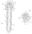
- Figure 1 shows a longitudinal section through a metal spray nozzle 10 according to the invention.
- the metal spray nozzle 10 has a nozzle tube 11, only partially shown, in which a melt channel 12 is formed, the one in which is not shown in detail A metal melt is supplied as indicated by the arrow S.
- nozzle tube heaters 13 which are arranged offset in its axial longitudinal extent and which are preferably electrical resistance heaters and which are surrounded by an outer jacket tube 17.
- the nozzle tube 11 is connected to a nozzle head 14.
- the nozzle head 14 has a base body 15, in which a recess 22 is provided on the side facing the nozzle tube 11 (see Figure 2 ) is formed, in which the end of the nozzle tube 11 can be inserted with a tight fit.
- a distribution chamber 19 is formed in the base body 15 of the nozzle head 14, which is aligned on its upstream side with the melt channel 12 of the nozzle tube 11 and merges smoothly into the latter.
- a plurality of heating elements 16 are arranged in the nozzle head 14 on both sides of the distributor chamber 19, with which the metal melt located in the distributor chamber 19 can be heated or kept at a predetermined temperature.
- a plurality of branch channels 20 branch off from the distribution chamber 19 and each open out on the downstream end face 26 of the nozzle head 14 facing away from the nozzle tube 11, each forming a nozzle opening 25.
- a plurality of cooling elements 24 are formed in the nozzle head 14, for example in the form of cooling channels through which cooling liquid flows.
- the Cooling channels 24 can be controlled individually and / or in groups. How Figure 2 shows, the cooling elements 24 are each formed on opposite sides of each nozzle opening 25.
- a central region 18 of the base body 15 of the nozzle head 14 has the branch channels 20 flowing around it.
- a further heating element 21 is arranged near the nozzle openings 25.
- the further heating element 21 can be, for example, an electrical resistance heater.
- a plurality of further cooling elements 23 are formed in the base body 15 of the nozzle head 14, which are preferably cooling ducts through which cooling liquid flows.
- the cooling elements 23 can be controlled individually and / or in groups.
- the arrangement of the cooling elements 23 is such that the branch channels 20 each run between at least two cooling elements 23 and are thus cooled on both sides.
- the branch channels 20 and the nozzle openings 25 are preferably dimensioned such that the same amount of molten metal emerges from the nozzle openings 25.
- the nozzle head 14 is detached from the nozzle tube 11 and exchanged for another nozzle head, which is preferably a different number and one another arrangement of branch channels and nozzle openings - has.
- the cooling elements 23 and 24 in the nozzle head 14 are activated, the metal melt, which is located in the region of the nozzle openings 25 within the branch channels 20, solidifying, as a result of which the metal spray nozzle 10 is opened up. If the injection molding process is to be restarted, the cooling elements 23 and 24 are either switched off or their cooling effect is reduced and the heating elements 16 and in particular the further heating element 21 arranged near the nozzle openings 25 are activated, as a result of which the molten metal which is located in the branch channels 20 is heated and liquefied, so that the metal spray nozzle is released again.
Landscapes
- Engineering & Computer Science (AREA)
- Mechanical Engineering (AREA)
- Injection Moulding Of Plastics Or The Like (AREA)
Description
- Die Erfindung betrifft eine Metallspritzdüse zum Spritzgießen einer flüssigen Metall-Komponente mit den Merkmalen des Oberbegriffs des Anspruchs 1.
- Aus dem Stand der Technik sind verschiedene Verfahren und Vorrichtungen bekannt, um eine Metallschmelze in einem Spritzgusswerkzeug zu verwenden. Dabei kann ein herzustellendes Bauteil entweder vollständig aus Metall bestehen, alternativ ist es jedoch auch möglich, eine Metall-Komponente an ein vorgefertigtes Bauteil anzuspritzen, das beispielsweise aus Kunststoff bestehen kann.
- Um eine flüssige Metallschmelze ordnungsgemäß spritzen zu können, muss diese eine geringe Viskosität aufweisen, d.h. sehr fließfähig sein. Üblicherweise finden deshalb Metall-Legierungen Verwendung. Zusätzlich ist es notwendig, die Metall-Schmelze in der Metallspritzdüse, mit der sie in eine Kavität eines Werkzeugs oder einer Form eingespritzt wird, zu erwärmen bzw. auf einer vorbestimmten Temperatur und somit fließfähig zu halten.
- Aus der
DE 10 2012 009 790 A1 ist eine Düse um Spritzen von Metall bekannt, die eine einzelne Düsenöffnung aufweist, die mittels eines Nadelventils verschlossen werden kann. Die Düsenöffnung ist dabei in einem Düsenkopf ausgebildet, der mittels einer Kühlvorrichtung gekühlt werden kann, so dass das im Angussbereich befindliche Metall erstarrt und in einem späteren Verfahrensschritt wieder durch Erwärmung verflüssigt werden kann. - Es hat sich gezeigt, dass es in der Praxis häufig gewünscht ist, die Anzahl und/oder die Lage der Düsenöffnungen in Abhängigkeit von dem zu spritzenden Bauteil zu verändern. Bei der Metallspritzdüse gemäß der
DE 10 2012 009 790 A1 ist es dazu notwendig, die Düse in ihrer Gesamtheit auszubauen, was nicht nur zeitaufwändig, sondern auch kostenintensiv ist. - In der
DE 23 38 458 A1 , von der im Oberbegriff des Anspruchs 1 ausgegangen wird, ist eine Düse einer Spritzgießmaschine gezeigt, die einen auswechselbar gelagerten Düsenkopf aufweist, in dem mehrere, sich verzweigende Zweigkanäle ausgebildet sind, die jeweils in einer Düsenöffnung münden. In dem Düsenkopf sind Heizpatronen angeordnet, die mit Abstand neben den Zweigkanälen positioniert sind. Mit der Düse können unterschiedlich fließfähige Materialien in einen Formhohlraum eingespritzt werden. Aufgrund der Auswechselbarkeit des Düsenkopfes ist eine gewisse Anpassbarkeit an unterschiedliche, zu spritzende Materialien möglich, jedoch ist eine Anpassung an unterschiedliche Materialien hinsichtlich der Umgebungstemperatur nur in sehr eingeschränktem Maße möglich. Mittels der im Düsenkopf angeordneten Heizvorrichtung kann eine allmähliche Erwärmung der Wandungen der Zweigkanäle erreicht werden, es hat sich jedoch gezeigt, dass bei der Umstellung auf eine andere Temperatur eine lange Stillstandszeit notwendig ist, bis in den Zweigkanälen die gewünschte Verarbeitungstemperatur herrscht. - Die
DE 695 10 751 T2 und dieUS 3,568,256 A zeigen ebenfalls eine Spritzdüse mit sich verzweigenden Zweigkanälen, jedoch ist dabei weder ein Heizelement noch ein Kühlelement vorgesehen. Auf diese Weise können diese Spritzdüsen eine Metallschmelze nicht in gewünschter Weise temperieren. - Der Erfindung liegt die Aufgabe zugrunde, eine Düse der genannten Art zu schaffen, die in einfacher und schneller Weise hinsichtlich der Umgebungstemperatur an unterschiedliche Materialien anpassbar ist.
- Diese Aufgabe wird erfindungsgemäß durch eine Metallspritzdüse mit den Merkmalen des Anspruchs 1 gelöst. Dabei ist in bekannter Weise vorgesehen, dass der Düsenkopf auswechselbar gehalten ist und dass in dem Düsenkopf mehrere Zweigkanäle ausgebildet sind, die jeweils in einer Düsenöffnung münden, wobei in den Düsenkopf zumindest ein Heizelement integriert ist.
- Erfindungsgemäß wird von der Grundüberlegung ausgegangen, das Düsenrohr der Metallspritzdüse, das einen Schmelzekanal bildet, nicht einstückig mit dem Düsenkopf auszubilden, sondern den Düsenkopf auswechselbar zu lagern und insbesondere am Düsenrohr anzubringen. Auf diese Weise ist es möglich, durch Auswechseln des Düsenkopfes die Anzahl der Düsenöffnungen und auch deren relative Position an die jeweiligen spritztechnischen Anforderungen anzupassen.
- In den Düsenkopf ist zumindest ein Heizelement integriert, wobei es sich vorzugsweise um ein elektrisches Widerstands-Heizelement handelt. Alternativ oder zusätzlich dazu können auch Heizkanäle vorgesehen sein, die von einem heißen Fluid und insbesondere einer heißen Flüssigkeit durchströmt sind.
- Die in den Düsenkopf integrierten Heizelemente sorgen dafür, dass die Metallschmelze auf eine vorbestimmte Temperatur erwärmt bzw. auf dieser gehalten wird. Falls bei speziellen Metallschmelzen relativ hohe Temperaturen gewünscht sind, kann dies dadurch erreicht werden, dass der Düsenkopf gegen einen entsprechend konfigurierten anderen Düsenkopf ausgewechselt wird, was durch die lösbare Anbringung gewährleistet ist.
- Die Anzahl der Zweigkanäle in dem Düsenkopf ist grundsätzlich beliebig, jedoch hat es sich in der Praxis bewährt, zwei bis fünf und vorzugsweise zwei oder drei Zweigkanäle vorzusehen. Die Erfindung ist jedoch darauf nicht beschränkt.
- Aufgrund der Auswechselbarkeit des Düsenkopfes ist es möglich, dass ein Benutzer wahlweise Düsenköpfe unterschiedlicher Ausgestaltung anbringen kann. Die Düsenköpfe können dabei unterschiedliche Formen und Größen besitzen. Zusätzlich oder alternativ dazu können auch Düsenköpfe mit einer unterschiedlichen Anzahl und gegenseitigen Anordnung von Zweigkanälen und Düsenöffnungen verwendet werden.
- Gemäß der Erfindung ist vorgesehen, dass zumindest eines der Heizelemente im Bereich zwischen den Zweigkanälen angeordnet ist. Auf diese Weise kann erreicht werden, dass die in den Zweigkanälen und insbesondere nahe den Düsenöffnungen befindliche Metallschmelze im Bedarfsfall schnell auf die gewünschte Temperatur erwärmt werden kann.
- Gemäß der Erfindung ist auch vorgesehen, dass in dem Düsenkopf zumindest ein Kühlelement angeordnet ist. Bei dem Kühlelement kann es sich beispielsweise um ein oder mehrere von einem gekühlten Fluid, insbesondere einer Flüssigkeit durchströmte Kühlkanäle oder auch um ein elektrisches Kühlelement, beispielsweise ein Peltier-Element handeln.
- Dabei ist vorgesehen, dass zumindest eines der Kühlelemente im Bereich zwischen den Zweigkanälen angeordnet ist. Auf diese Weise ist es möglich, für eine sehr schnelle Erstarrung der Metallschmelze in den Zweigkanälen im Be-reich der Düsenöffnungen zu sorgen.
- Vorzugsweise ist jedem Zweikanal zumindest ein Kühlelement zugeordnet. Die Kühlelemente können dazu verwendet werden, die Metallschmelze im Bereich der Düsenöffnungen bei Bedarf so weit abzukühlen, dass sie erstarrt und damit die Metallspritzdüse in thermischer Weise verschlossen wird. Wenn der Spritzgussvorgang fortgesetzt werden soll, wird die Kühlung der Metallschmelze unterbrochen und/oder die Metallschmelze erwärmt, wodurch sie sich wieder verflüssigt und die Düsenöffnungen wieder freigegeben sind.
- Um einzelne Düsenöffnungen bei Bedarf zu verschließen oder verschlossen zu halten, kann in Weiterbildung der Erfindung vorgesehen sein, dass die Heizelemente und/oder die Kühlelemente einzeln und/oder gruppenweise ansteuerbar sind. Dies ermöglicht es, bei Bedarf nur einige der Düsenöffnungen durch Kühlung und Erstarren der Metallschmelze zu verschließen und/oder bei Bedarf nur einige der durch erstarrte Metallschmelze verschlossenen Düsenöffnungen durch Verflüssigung der Metallschmelze wieder freizugeben.
- In bevorzugter Ausgestaltung der Erfindung ist vorgesehen, dass in dem Düsenkopf eine Verteilerkammer ausgebildet ist, von der aus die Zweigkanäle abzweigen. Auf diese Weise ist sichergestellt, dass die Zweigkanäle alle zuverlässig mit der Metallschmelze gefüllt werden.
- Mit Hilfe des auswechselbaren Düsenkopfes ist es auch möglich, Düsenköpfe zu verwenden, die auf ihrer dem Düsenrohr abgewandten Stirnseite, in der die Düsenöffnungen ausgebildet sind, unterschiedliche geometrische Gestaltungen besitzen. In einer möglichen Ausgestaltung der Erfindung ist vorgesehen, dass die dem Grundteil abgewandte Stirnseite des Verteilerelementes eben und vorzugsweise in einem rechten Winkel zur Austrittsrichtung der Metallschmelze ausgebildet ist. Alternativ dazu kann vorgesehen sein, dass die dem Düsenrohr abgewandte Stirnseite des Düsenkopfes zumindest einen hervorstehenden Ansatz aufweist, in dem zumindest eine Düsenöffnung ausgebildet ist. Somit ist die Stirnseite des Düsenkopfes terrassenförmig strukturiert und kann damit hinsichtlich der Fließwege der Metallschmelze innerhalb des Düsenkopfes verändert und auch an die Geometrie eines zu spritzenden Bauteils angepasst werden.
- Die Erfindung beschreibt somit einen auswechselbaren Düsenkopf mit vorzugsweise mehreren Zweigkanälen für das Verteilen der Lotschmelze. Dabei sind die Zweigkanäle von integrierten in einer Ebene (2D) oder im Raum (3D) angeordneten Kanälen für ein Kühlmedium umgeben, die nach Beendigung eines Einspritzvorgangs mit einem Kühlmedium durchströmt werden, so dass die Metallschmelze unterhalb des Erstarrungspunktes abkühlt. Der Düsenkopf wird bevorzugt auf eine Temperatur von 5°C bis 100°C unterhalb der Solidustemperatur abgekühlt. Durch die darunterliegende Heizvorrichtung wird der Düsenkopf später bevorzugt auf 10°C bis 150°C oberhalb der Liquidustemperatur aufgeheizt. Um eine gleichmäßige Druckverteilung zu gewährleisten, können die Abschnitte an das zu spritzende Bauteil unterschiedliche Querschnitte aufweisen. Die Stirnseite des Düsenkopfes kann dabei zweidimensional als auch dreidimensional ausgebildet sein.
- Weitere Einzelheiten und Merkmale der Erfindung sind aus der folgenden Beschreibung eines Ausführungsbeispiels unter Bezugnahme auf die Zeichnungen ersichtlich. Es zeigen:
- Fig. 1
- einen ausschnittsweisen Längsschnitt durch eine erfindungsgemäße Metallspritzdüse und
- Fig. 2
- eine perspektivische vergrößerte Schnittansicht eines Düsenkopfes.
-
Figur 1 zeigt einen Längsschnitt durch eine erfindungsgemäße Metallspritzdüse 10. Die Metallspritzdüse 10 besitzt ein nur teilweise dargestelltes Düsenrohr 11, in dem ein Schmelzekanal 12 ausgebildet ist, dem in nicht näher dargestellter Weise eine Metallschmelze zugeführt wird, wie es durch den Pfeil S angedeutet ist. - Auf der Außenseite des Düsenrohres 11 sind in dessen axialer Längserstreckung versetzt angeordnete Düsenrohrheizungen 13 vorgesehen, bei denen es sich vorzugsweise um elektrische Widerstandsheizungen handelt und die von einem außenseitigen Mantelrohr 17 umgeben sind.
- An seinem in Strömungsrichtung der Metallschmelze stromab liegenden, gemäß
Figur 1 rechten Ende ist das Düsenrohr 11 an einen Düsenkopf 14 angeschlossen. Der Düsenkopf 14 weist einen Grundkörper 15 auf, in dem auf der dem Düsenrohr 11 zugewandten Seite eine Ausnehmung 22 (sieheFigur 2 ) ausgebildet ist, in die das Ende des Düsenrohres 11 unter enger Passung einsetzbar ist. Stromab der Ausnehmung 22 ist in dem Grundkörper 15 des Düsenkopfes 14 eine Verteilerkammer 19 ausgebildet, die auf ihrer stromauf liegenden Seite mit dem Schmelzekanal 12 des Düsenrohres 11 fluchtet und stufenlos in diesen übergeht. - Beidseitig der Verteilerkammer 19 sind in dem Düsenkopf 14 mehrere Heizelemente 16 angeordnet, mit denen die in der Verteilerkammer 19 befindliche Metallschmelze erwärmt bzw. in einer vorbestimmten Temperatur gehalten werden kann.
- Von der Verteilerkammer 19 zweigen mehrere Zweigkanäle 20 ab, die auf der dem Düsenrohr 11 abgewandten, stromab liegenden Stirnseite 26 des Düsenkopfes 14 jeweils unter Bildung einer Düsenöffnung 25 münden. Im Bereich der Düsenöffnungen 25 bzw. Mündungen sind in dem Düsenkopf 14 mehrere Kühlelemente 24 beispielsweise in Form von mit Kühlflüssigkeit durchströmten Kühlkanälen ausgebildet. Die Kühlkanäle 24 können einzeln und/oder gruppenweise angesteuert werden. Wie
Figur 2 zeigt, sind die Kühlelemente 24 jeweils auf entgegengesetzten Seiten jeder Düsenöffnung 25 ausgebildet. - Ein mittlerer Bereich 18 des Grundkörpers 15 des Düsenkopfes 14 ist von den Zweigkanälen 20 umströmt. In diesem zwischen den Zweigkanälen 20 liegenden Bereich 18 des Düsenkopfes 14 ist ein weiteres Heizelement 21 nahe den Düsenöffnungen 25 angeordnet. Bei dem weiteren Heizelement 21 kann es sich beispielsweise um eine elektrische Widerstandsheizung handeln.
- Im Bereich der Zweigkanäle 20 etwa auf halber Strecke zwischen der Verteilerkammer 19 und den Düsenöffnungen 25 sind im Grundkörper 15 des Düsenkopfes 14 mehrere weitere Kühlelemente 23 ausgebildet, bei denen es sich vorzugsweise um mit Kühlflüssigkeit durchströmten Kühlkanäle handelt. Die Kühlelemente 23 können einzeln und/oder gruppenweise angesteuert werden. Die Anordnung der Kühlelemente 23 ist dabei so getroffen, dass die Zweigkanäle 20 jeweils zwischen zumindest zwei Kühlelementen 23 verlaufen und somit auf beiden Seiten gekühlt sind.
- Vorzugsweise sind die Zweigkanäle 20 und die Düsenöffnungen 25 so dimensioniert, dass an den Düsenöffnungen 25 jeweils die gleiche Menge an Metallschmelze austritt.
- Wenn die Metallspritzdüse an andere spritztechnische Anforderungen angepasst werden soll, wird der Düsenkopf 14 vom Düsenrohr 11 gelöst und gegen einen anderen Düsenkopf ausgewechselt, der vorzugsweise eine andere Anzahl und eine andere Anordnung von Zweigkanälen und Düsenöffnungen - besitzt.
- Nach Abschluss eines Spritzgussvorgangs werden die Kühlelemente 23 und 24 in dem Düsenkopf 14 aktiviert, wobei die Metallschmelze, die sich im Bereich der Düsenöffnungen 25 innerhalb der Zweigkanäle 20 befindet, erstarrt, wodurch die Metallspritzdüse 10 erschlossen ist. Wenn der Spritzgussvorgang wieder aufgenommen werden soll, werden die Kühlelemente 23 und 24 entweder abgeschaltet oder in ihrer Kühlwirkung reduziert und die Heizelemente 16 und insbesondere das weitere nahe den Düsenöffnungen 25 angeordnete Heizelement 21 aktiviert, wodurch die Metallschmelze, die sich in den Zweigkanälen 20 befindet, erwärmt wird und sich verflüssigt, so dass die Metallspritzdüse wieder freigegeben ist.
Claims (7)
- Metallspritzdüse (10) mit einem Düsenrohr (11), das einen Schmelzekanal (12) bildet und das mittels zumindest einer Düsenrohrheizung (13) beheizbar ist, und mit einem Düsenkopf (14), der zumindest eine Düsenöffnung (25) für den Schmelze-Austritt aufweist, wobei der Düsenkopf (14) auswechselbar gehalten ist und wobei in dem Düsenkopf (14) mehrere Zweigkanäle (20) ausgebildet sind, die jeweils in einer Düsenöffnung (25) münden, wobei in den Düsenkopf (14) zumindest ein Heizelement (16, 21) integriert ist, dadurch gekennzeichnet, dass zumindest eines der Heizelemente (21) im Bereich zwischen den Zweigkanälen (20) angeordnet ist und dass in dem Düsenkopf (14) zumindest ein Kühlelement (23, 24) angeordnet ist, wobei zumindest eines der Kühlelemente (24) im Bereich zwischen den Zweigkanälen (20) angeordnet ist.
- Metallspritzdüse nach Anspruch 1, dadurch gekennzeichnet, dass jedem Zweigkanal (20) zumindest ein Kühlelement (23) zugeordnet ist.
- Metallspritzdüse nach Anspruch 2, dadurch gekennzeichnet, dass die Heizelemente (16, 21) und/oder die Kühlelemente (23, 24) einzeln und/oder gruppenweise ansteuerbar sind.
- Metallspritzdüse nach einem der Ansprüche 1 bis 3, dadurch gekennzeichnet, dass in dem Düsenkopf (14) eine Verteilerkammer (19) ausgebildet ist, von der aus die Zweigkanäle (20) abzweigen.
- Metallspritzdüse nach Anspruch 4, dadurch gekennzeichnet, dass zumindest eines der Heizelemente (16) nahe der Verteilerkammer (19) angeordnet ist.
- Metallspritzdüse nach einem der Ansprüche 1 bis 5, dadurch gekennzeichnet, dass die dem Düsenrohr (11) abgewandte Stirnseite (26) des Düsenkopfes (14) eben ausgebildet ist.
- Metallspritzdüse nach einem der Ansprüche 1 bis 6, dadurch gekennzeichnet, dass die dem Düsenrohr (11) abgewandte Stirnseite (26) des Düsenkopfes (14) zumindest einen hervorstehenden Ansatz aufweist, in dem zumindest eine Düsenöffnung (25) ausgebildet ist.
Applications Claiming Priority (2)
| Application Number | Priority Date | Filing Date | Title |
|---|---|---|---|
| DE102014018794.2A DE102014018794A1 (de) | 2014-12-19 | 2014-12-19 | Metallspritzdüse zum Spritzgießen einer flüssigen Metall-Komponente |
| PCT/EP2015/002519 WO2016096122A1 (de) | 2014-12-19 | 2015-12-15 | Metallspritzdüse zum spritzgiessen einer flüssigen metall-komponente |
Publications (2)
| Publication Number | Publication Date |
|---|---|
| EP3233333A1 EP3233333A1 (de) | 2017-10-25 |
| EP3233333B1 true EP3233333B1 (de) | 2020-02-05 |
Family
ID=55080078
Family Applications (1)
| Application Number | Title | Priority Date | Filing Date |
|---|---|---|---|
| EP15822910.4A Active EP3233333B1 (de) | 2014-12-19 | 2015-12-15 | Metallspritzdüse zum spritzgiessen einer flüssigen metall-komponente |
Country Status (3)
| Country | Link |
|---|---|
| EP (1) | EP3233333B1 (de) |
| DE (1) | DE102014018794A1 (de) |
| WO (1) | WO2016096122A1 (de) |
Family Cites Families (11)
| Publication number | Priority date | Publication date | Assignee | Title |
|---|---|---|---|---|
| AT106047B (de) * | 1924-09-24 | 1927-03-25 | Lanston Monotype Corp Ltd | Gießtopfdüse. |
| US3568256A (en) * | 1968-07-15 | 1971-03-09 | J & J Machine Co Inc | Plastic feeder head |
| DE2338458A1 (de) * | 1973-07-28 | 1975-02-06 | Karl Hehl | Mehrfachduese einer spritzgiessmaschine |
| DE3001017A1 (de) * | 1980-01-12 | 1981-07-16 | Heinz 7203 Fridingen Stegmeier | Heisskanalduese fuer eine spritzgussmaschine |
| US5522720A (en) * | 1994-10-24 | 1996-06-04 | Husky Injection Molding Systems Ltd. | Injector nozzle with pivotally movable surfaces |
| JP3991340B2 (ja) * | 1998-04-07 | 2007-10-17 | 株式会社十王 | 射出成形用ノズル |
| DE19942197A1 (de) * | 1999-09-03 | 2001-03-08 | Gerhard Schoch | Druckgiessmaschine mit Konusschleifkörper |
| DE102006026579A1 (de) * | 2006-06-08 | 2007-12-13 | Günther Heisskanaltechnik Gmbh | Spritzgussdüse, insbesondere Heißkanaldüse, zur Anordnung in einem Spritzgießwerkzeug |
| JP2009262215A (ja) * | 2008-04-28 | 2009-11-12 | Japan Steel Works Ltd:The | 金型装置及び射出成形方法 |
| DE102011050149A1 (de) * | 2010-11-17 | 2012-05-24 | Ferrofacta Gmbh | Druckgussdüse und Druckgussverfahren |
| DE102012009790A1 (de) | 2012-05-18 | 2013-11-21 | Gebr. Krallmann Gmbh | Verfahren zum Spritzgießen einer flüssigen Metall-Komponente und Düse zum SpritzenMetall |
-
2014
- 2014-12-19 DE DE102014018794.2A patent/DE102014018794A1/de not_active Withdrawn
-
2015
- 2015-12-15 EP EP15822910.4A patent/EP3233333B1/de active Active
- 2015-12-15 WO PCT/EP2015/002519 patent/WO2016096122A1/de not_active Ceased
Non-Patent Citations (1)
| Title |
|---|
| None * |
Also Published As
| Publication number | Publication date |
|---|---|
| EP3233333A1 (de) | 2017-10-25 |
| DE102014018794A1 (de) | 2016-06-23 |
| WO2016096122A1 (de) | 2016-06-23 |
Similar Documents
| Publication | Publication Date | Title |
|---|---|---|
| DE4234961C2 (de) | Verfahren zur Herstellung eines Formwerkzeuges für die Herstellung von Kunststofformteilen | |
| DE10201830A1 (de) | Düsenende für eine Spritzgussdüse mit mehreren Spitzen | |
| EP3634665B1 (de) | Kühlmitteldüse zum kühlen eines metallischen strangs in einer stranggussanlage | |
| DE4323038A1 (de) | Spritzdüse mit abnehmbarem vorderen Teil | |
| AT516225B1 (de) | Verfahren und Spritzgussdüse zum Herstellen von Spritzgussteilen aus Kunststoff | |
| DE3113294A1 (de) | "verfahren zur herstellung einer keramischen investmentgiessform" | |
| DE102005024331A1 (de) | Ventilbetätigte Spritzgießdüse mit einer Ringströmungsspitze | |
| DE2356764B2 (de) | Heißkanal-Spritzgießwerkzeug mit mehreren Formhohlräumen | |
| DE102014009437A1 (de) | Modulare Seitenangießdüse und Gießform | |
| EP2026945B1 (de) | Spritzgussdüse, insbesondere Heisskanaldüse, zur Anordnung in einem Spritzgiesswerkzeug | |
| DE102007052597A1 (de) | Angußadapter sowie Angußsystem für einen Angußadapter | |
| DE102014001563B4 (de) | Gussform | |
| DE10255938B4 (de) | Gering beabstandete Düse mit einem thermisch leitfähigen Einsatz für eine Spritzgießvorrichtung | |
| DE1964109C3 (de) | Mehrteilige Spritzgießform für Formkörper aus Kunststoff, mit einem längs eines Verteilerkanals angeordneten Temperierelement | |
| WO2016193458A1 (de) | Heisskanal-angusssystem für eine druckgiessform | |
| EP3233332B1 (de) | Metallspritzdüse zum spritzgiessen einer flüssigen metall-komponente | |
| DE102010017014A1 (de) | Verfahren und Anordnung zur Herstellung von konturbezogenen Temperierkanälen in Werkzeugen bzw. Werkzeugeinsätzen, Kernen und Schiebern | |
| DE3538206A1 (de) | Warmspritzduese zur verwendung mit einer pressform zum eingusslosen spritzen von kunststoffmaterial | |
| DE4442667C2 (de) | Spritzgussvorrichtung mit senkrechten beheizten Angüssen | |
| WO2016096122A1 (de) | Metallspritzdüse zum spritzgiessen einer flüssigen metall-komponente | |
| DE19522716C1 (de) | Vorrichtung zur Beheizung von Verteilerrohren zum Zuführen von Fluiden | |
| AT518450A1 (de) | Verfahren und Kühleinrichtung zum Kühlen eines metallischen Strangs | |
| EP1685916B1 (de) | Verbundgußplatte | |
| EP3233331B1 (de) | Fördervorrichtung für eine metallschmelze in einem spritzgussaggregat | |
| DE10327630B3 (de) | Formvorrichtung zum Rotationsformen |
Legal Events
| Date | Code | Title | Description |
|---|---|---|---|
| STAA | Information on the status of an ep patent application or granted ep patent |
Free format text: STATUS: THE INTERNATIONAL PUBLICATION HAS BEEN MADE |
|
| PUAI | Public reference made under article 153(3) epc to a published international application that has entered the european phase |
Free format text: ORIGINAL CODE: 0009012 |
|
| STAA | Information on the status of an ep patent application or granted ep patent |
Free format text: STATUS: REQUEST FOR EXAMINATION WAS MADE |
|
| 17P | Request for examination filed |
Effective date: 20170717 |
|
| AK | Designated contracting states |
Kind code of ref document: A1 Designated state(s): AL AT BE BG CH CY CZ DE DK EE ES FI FR GB GR HR HU IE IS IT LI LT LU LV MC MK MT NL NO PL PT RO RS SE SI SK SM TR |
|
| AX | Request for extension of the european patent |
Extension state: BA ME |
|
| DAV | Request for validation of the european patent (deleted) | ||
| DAX | Request for extension of the european patent (deleted) | ||
| STAA | Information on the status of an ep patent application or granted ep patent |
Free format text: STATUS: EXAMINATION IS IN PROGRESS |
|
| 17Q | First examination report despatched |
Effective date: 20181106 |
|
| GRAP | Despatch of communication of intention to grant a patent |
Free format text: ORIGINAL CODE: EPIDOSNIGR1 |
|
| STAA | Information on the status of an ep patent application or granted ep patent |
Free format text: STATUS: GRANT OF PATENT IS INTENDED |
|
| INTG | Intention to grant announced |
Effective date: 20190906 |
|
| GRAS | Grant fee paid |
Free format text: ORIGINAL CODE: EPIDOSNIGR3 |
|
| GRAA | (expected) grant |
Free format text: ORIGINAL CODE: 0009210 |
|
| STAA | Information on the status of an ep patent application or granted ep patent |
Free format text: STATUS: THE PATENT HAS BEEN GRANTED |
|
| AK | Designated contracting states |
Kind code of ref document: B1 Designated state(s): AL AT BE BG CH CY CZ DE DK EE ES FI FR GB GR HR HU IE IS IT LI LT LU LV MC MK MT NL NO PL PT RO RS SE SI SK SM TR |
|
| REG | Reference to a national code |
Ref country code: GB Ref legal event code: FG4D Free format text: NOT ENGLISH |
|
| REG | Reference to a national code |
Ref country code: AT Ref legal event code: REF Ref document number: 1229555 Country of ref document: AT Kind code of ref document: T Effective date: 20200215 |
|
| REG | Reference to a national code |
Ref country code: DE Ref legal event code: R096 Ref document number: 502015011660 Country of ref document: DE |
|
| REG | Reference to a national code |
Ref country code: IE Ref legal event code: FG4D Free format text: LANGUAGE OF EP DOCUMENT: GERMAN |
|
| REG | Reference to a national code |
Ref country code: CH Ref legal event code: EP |
|
| REG | Reference to a national code |
Ref country code: NL Ref legal event code: MP Effective date: 20200205 |
|
| PG25 | Lapsed in a contracting state [announced via postgrant information from national office to epo] |
Ref country code: RS Free format text: LAPSE BECAUSE OF FAILURE TO SUBMIT A TRANSLATION OF THE DESCRIPTION OR TO PAY THE FEE WITHIN THE PRESCRIBED TIME-LIMIT Effective date: 20200205 Ref country code: FI Free format text: LAPSE BECAUSE OF FAILURE TO SUBMIT A TRANSLATION OF THE DESCRIPTION OR TO PAY THE FEE WITHIN THE PRESCRIBED TIME-LIMIT Effective date: 20200205 Ref country code: NO Free format text: LAPSE BECAUSE OF FAILURE TO SUBMIT A TRANSLATION OF THE DESCRIPTION OR TO PAY THE FEE WITHIN THE PRESCRIBED TIME-LIMIT Effective date: 20200505 Ref country code: PT Free format text: LAPSE BECAUSE OF FAILURE TO SUBMIT A TRANSLATION OF THE DESCRIPTION OR TO PAY THE FEE WITHIN THE PRESCRIBED TIME-LIMIT Effective date: 20200628 |
|
| REG | Reference to a national code |
Ref country code: LT Ref legal event code: MG4D |
|
| PG25 | Lapsed in a contracting state [announced via postgrant information from national office to epo] |
Ref country code: BG Free format text: LAPSE BECAUSE OF FAILURE TO SUBMIT A TRANSLATION OF THE DESCRIPTION OR TO PAY THE FEE WITHIN THE PRESCRIBED TIME-LIMIT Effective date: 20200505 Ref country code: SE Free format text: LAPSE BECAUSE OF FAILURE TO SUBMIT A TRANSLATION OF THE DESCRIPTION OR TO PAY THE FEE WITHIN THE PRESCRIBED TIME-LIMIT Effective date: 20200205 Ref country code: LV Free format text: LAPSE BECAUSE OF FAILURE TO SUBMIT A TRANSLATION OF THE DESCRIPTION OR TO PAY THE FEE WITHIN THE PRESCRIBED TIME-LIMIT Effective date: 20200205 Ref country code: HR Free format text: LAPSE BECAUSE OF FAILURE TO SUBMIT A TRANSLATION OF THE DESCRIPTION OR TO PAY THE FEE WITHIN THE PRESCRIBED TIME-LIMIT Effective date: 20200205 Ref country code: GR Free format text: LAPSE BECAUSE OF FAILURE TO SUBMIT A TRANSLATION OF THE DESCRIPTION OR TO PAY THE FEE WITHIN THE PRESCRIBED TIME-LIMIT Effective date: 20200506 Ref country code: IS Free format text: LAPSE BECAUSE OF FAILURE TO SUBMIT A TRANSLATION OF THE DESCRIPTION OR TO PAY THE FEE WITHIN THE PRESCRIBED TIME-LIMIT Effective date: 20200605 |
|
| PG25 | Lapsed in a contracting state [announced via postgrant information from national office to epo] |
Ref country code: NL Free format text: LAPSE BECAUSE OF FAILURE TO SUBMIT A TRANSLATION OF THE DESCRIPTION OR TO PAY THE FEE WITHIN THE PRESCRIBED TIME-LIMIT Effective date: 20200205 |
|
| PG25 | Lapsed in a contracting state [announced via postgrant information from national office to epo] |
Ref country code: SK Free format text: LAPSE BECAUSE OF FAILURE TO SUBMIT A TRANSLATION OF THE DESCRIPTION OR TO PAY THE FEE WITHIN THE PRESCRIBED TIME-LIMIT Effective date: 20200205 Ref country code: CZ Free format text: LAPSE BECAUSE OF FAILURE TO SUBMIT A TRANSLATION OF THE DESCRIPTION OR TO PAY THE FEE WITHIN THE PRESCRIBED TIME-LIMIT Effective date: 20200205 Ref country code: RO Free format text: LAPSE BECAUSE OF FAILURE TO SUBMIT A TRANSLATION OF THE DESCRIPTION OR TO PAY THE FEE WITHIN THE PRESCRIBED TIME-LIMIT Effective date: 20200205 Ref country code: ES Free format text: LAPSE BECAUSE OF FAILURE TO SUBMIT A TRANSLATION OF THE DESCRIPTION OR TO PAY THE FEE WITHIN THE PRESCRIBED TIME-LIMIT Effective date: 20200205 Ref country code: SM Free format text: LAPSE BECAUSE OF FAILURE TO SUBMIT A TRANSLATION OF THE DESCRIPTION OR TO PAY THE FEE WITHIN THE PRESCRIBED TIME-LIMIT Effective date: 20200205 Ref country code: EE Free format text: LAPSE BECAUSE OF FAILURE TO SUBMIT A TRANSLATION OF THE DESCRIPTION OR TO PAY THE FEE WITHIN THE PRESCRIBED TIME-LIMIT Effective date: 20200205 Ref country code: LT Free format text: LAPSE BECAUSE OF FAILURE TO SUBMIT A TRANSLATION OF THE DESCRIPTION OR TO PAY THE FEE WITHIN THE PRESCRIBED TIME-LIMIT Effective date: 20200205 Ref country code: DK Free format text: LAPSE BECAUSE OF FAILURE TO SUBMIT A TRANSLATION OF THE DESCRIPTION OR TO PAY THE FEE WITHIN THE PRESCRIBED TIME-LIMIT Effective date: 20200205 |
|
| REG | Reference to a national code |
Ref country code: DE Ref legal event code: R097 Ref document number: 502015011660 Country of ref document: DE |
|
| PLBE | No opposition filed within time limit |
Free format text: ORIGINAL CODE: 0009261 |
|
| STAA | Information on the status of an ep patent application or granted ep patent |
Free format text: STATUS: NO OPPOSITION FILED WITHIN TIME LIMIT |
|
| 26N | No opposition filed |
Effective date: 20201106 |
|
| PG25 | Lapsed in a contracting state [announced via postgrant information from national office to epo] |
Ref country code: IT Free format text: LAPSE BECAUSE OF FAILURE TO SUBMIT A TRANSLATION OF THE DESCRIPTION OR TO PAY THE FEE WITHIN THE PRESCRIBED TIME-LIMIT Effective date: 20200205 |
|
| PG25 | Lapsed in a contracting state [announced via postgrant information from national office to epo] |
Ref country code: SI Free format text: LAPSE BECAUSE OF FAILURE TO SUBMIT A TRANSLATION OF THE DESCRIPTION OR TO PAY THE FEE WITHIN THE PRESCRIBED TIME-LIMIT Effective date: 20200205 Ref country code: PL Free format text: LAPSE BECAUSE OF FAILURE TO SUBMIT A TRANSLATION OF THE DESCRIPTION OR TO PAY THE FEE WITHIN THE PRESCRIBED TIME-LIMIT Effective date: 20200205 |
|
| REG | Reference to a national code |
Ref country code: CH Ref legal event code: PL |
|
| GBPC | Gb: european patent ceased through non-payment of renewal fee |
Effective date: 20201215 |
|
| PG25 | Lapsed in a contracting state [announced via postgrant information from national office to epo] |
Ref country code: MC Free format text: LAPSE BECAUSE OF FAILURE TO SUBMIT A TRANSLATION OF THE DESCRIPTION OR TO PAY THE FEE WITHIN THE PRESCRIBED TIME-LIMIT Effective date: 20200205 |
|
| REG | Reference to a national code |
Ref country code: BE Ref legal event code: MM Effective date: 20201231 |
|
| PG25 | Lapsed in a contracting state [announced via postgrant information from national office to epo] |
Ref country code: IE Free format text: LAPSE BECAUSE OF NON-PAYMENT OF DUE FEES Effective date: 20201215 Ref country code: FR Free format text: LAPSE BECAUSE OF NON-PAYMENT OF DUE FEES Effective date: 20201231 Ref country code: LU Free format text: LAPSE BECAUSE OF NON-PAYMENT OF DUE FEES Effective date: 20201215 |
|
| PG25 | Lapsed in a contracting state [announced via postgrant information from national office to epo] |
Ref country code: LI Free format text: LAPSE BECAUSE OF NON-PAYMENT OF DUE FEES Effective date: 20201231 Ref country code: GB Free format text: LAPSE BECAUSE OF NON-PAYMENT OF DUE FEES Effective date: 20201215 Ref country code: CH Free format text: LAPSE BECAUSE OF NON-PAYMENT OF DUE FEES Effective date: 20201231 |
|
| REG | Reference to a national code |
Ref country code: AT Ref legal event code: MM01 Ref document number: 1229555 Country of ref document: AT Kind code of ref document: T Effective date: 20201215 |
|
| PG25 | Lapsed in a contracting state [announced via postgrant information from national office to epo] |
Ref country code: AT Free format text: LAPSE BECAUSE OF NON-PAYMENT OF DUE FEES Effective date: 20201215 |
|
| PG25 | Lapsed in a contracting state [announced via postgrant information from national office to epo] |
Ref country code: TR Free format text: LAPSE BECAUSE OF FAILURE TO SUBMIT A TRANSLATION OF THE DESCRIPTION OR TO PAY THE FEE WITHIN THE PRESCRIBED TIME-LIMIT Effective date: 20200205 Ref country code: MT Free format text: LAPSE BECAUSE OF FAILURE TO SUBMIT A TRANSLATION OF THE DESCRIPTION OR TO PAY THE FEE WITHIN THE PRESCRIBED TIME-LIMIT Effective date: 20200205 Ref country code: CY Free format text: LAPSE BECAUSE OF FAILURE TO SUBMIT A TRANSLATION OF THE DESCRIPTION OR TO PAY THE FEE WITHIN THE PRESCRIBED TIME-LIMIT Effective date: 20200205 |
|
| PG25 | Lapsed in a contracting state [announced via postgrant information from national office to epo] |
Ref country code: MK Free format text: LAPSE BECAUSE OF FAILURE TO SUBMIT A TRANSLATION OF THE DESCRIPTION OR TO PAY THE FEE WITHIN THE PRESCRIBED TIME-LIMIT Effective date: 20200205 Ref country code: AL Free format text: LAPSE BECAUSE OF FAILURE TO SUBMIT A TRANSLATION OF THE DESCRIPTION OR TO PAY THE FEE WITHIN THE PRESCRIBED TIME-LIMIT Effective date: 20200205 |
|
| PG25 | Lapsed in a contracting state [announced via postgrant information from national office to epo] |
Ref country code: BE Free format text: LAPSE BECAUSE OF NON-PAYMENT OF DUE FEES Effective date: 20201231 |
|
| PGFP | Annual fee paid to national office [announced via postgrant information from national office to epo] |
Ref country code: DE Payment date: 20250115 Year of fee payment: 10 |