EP3233289B1 - Desaggregationsvorrichtung für biologisches material und zugehöriges herstellungsverfahren sowie verfahren zur herstellung von zellsuspensionen und gewebemikrotransplantaten - Google Patents
Desaggregationsvorrichtung für biologisches material und zugehöriges herstellungsverfahren sowie verfahren zur herstellung von zellsuspensionen und gewebemikrotransplantaten Download PDFInfo
- Publication number
- EP3233289B1 EP3233289B1 EP15828756.5A EP15828756A EP3233289B1 EP 3233289 B1 EP3233289 B1 EP 3233289B1 EP 15828756 A EP15828756 A EP 15828756A EP 3233289 B1 EP3233289 B1 EP 3233289B1
- Authority
- EP
- European Patent Office
- Prior art keywords
- disgregating
- biological material
- grid
- microholes
- bladed rotor
- Prior art date
- Legal status (The legal status is an assumption and is not a legal conclusion. Google has not performed a legal analysis and makes no representation as to the accuracy of the status listed.)
- Active
Links
Images


Classifications
-
- B—PERFORMING OPERATIONS; TRANSPORTING
- B02—CRUSHING, PULVERISING, OR DISINTEGRATING; PREPARATORY TREATMENT OF GRAIN FOR MILLING
- B02C—CRUSHING, PULVERISING, OR DISINTEGRATING IN GENERAL; MILLING GRAIN
- B02C18/00—Disintegrating by knives or other cutting or tearing members which chop material into fragments
- B02C18/06—Disintegrating by knives or other cutting or tearing members which chop material into fragments with rotating knives
- B02C18/08—Disintegrating by knives or other cutting or tearing members which chop material into fragments with rotating knives within vertical containers
- B02C18/10—Disintegrating by knives or other cutting or tearing members which chop material into fragments with rotating knives within vertical containers with drive arranged above container
-
- B—PERFORMING OPERATIONS; TRANSPORTING
- B02—CRUSHING, PULVERISING, OR DISINTEGRATING; PREPARATORY TREATMENT OF GRAIN FOR MILLING
- B02C—CRUSHING, PULVERISING, OR DISINTEGRATING IN GENERAL; MILLING GRAIN
- B02C18/00—Disintegrating by knives or other cutting or tearing members which chop material into fragments
- B02C18/30—Mincing machines with perforated discs and feeding worms
- B02C18/36—Knives or perforated discs
- B02C18/362—Knives
-
- B—PERFORMING OPERATIONS; TRANSPORTING
- B02—CRUSHING, PULVERISING, OR DISINTEGRATING; PREPARATORY TREATMENT OF GRAIN FOR MILLING
- B02C—CRUSHING, PULVERISING, OR DISINTEGRATING IN GENERAL; MILLING GRAIN
- B02C18/00—Disintegrating by knives or other cutting or tearing members which chop material into fragments
- B02C18/30—Mincing machines with perforated discs and feeding worms
- B02C18/36—Knives or perforated discs
- B02C18/365—Perforated discs
-
- B—PERFORMING OPERATIONS; TRANSPORTING
- B02—CRUSHING, PULVERISING, OR DISINTEGRATING; PREPARATORY TREATMENT OF GRAIN FOR MILLING
- B02C—CRUSHING, PULVERISING, OR DISINTEGRATING IN GENERAL; MILLING GRAIN
- B02C19/00—Other disintegrating devices or methods
- B02C19/20—Disintegrating by grating
-
- C—CHEMISTRY; METALLURGY
- C12—BIOCHEMISTRY; BEER; SPIRITS; WINE; VINEGAR; MICROBIOLOGY; ENZYMOLOGY; MUTATION OR GENETIC ENGINEERING
- C12M—APPARATUS FOR ENZYMOLOGY OR MICROBIOLOGY; APPARATUS FOR CULTURING MICROORGANISMS FOR PRODUCING BIOMASS, FOR GROWING CELLS OR FOR OBTAINING FERMENTATION OR METABOLIC PRODUCTS, i.e. BIOREACTORS OR FERMENTERS
- C12M21/00—Bioreactors or fermenters specially adapted for specific uses
- C12M21/08—Bioreactors or fermenters specially adapted for specific uses for producing artificial tissue or for ex-vivo cultivation of tissue
-
- C—CHEMISTRY; METALLURGY
- C12—BIOCHEMISTRY; BEER; SPIRITS; WINE; VINEGAR; MICROBIOLOGY; ENZYMOLOGY; MUTATION OR GENETIC ENGINEERING
- C12M—APPARATUS FOR ENZYMOLOGY OR MICROBIOLOGY; APPARATUS FOR CULTURING MICROORGANISMS FOR PRODUCING BIOMASS, FOR GROWING CELLS OR FOR OBTAINING FERMENTATION OR METABOLIC PRODUCTS, i.e. BIOREACTORS OR FERMENTERS
- C12M45/00—Means for pre-treatment of biological substances
- C12M45/02—Means for pre-treatment of biological substances by mechanical forces; Stirring; Trituration; Comminuting
-
- G—PHYSICS
- G01—MEASURING; TESTING
- G01N—INVESTIGATING OR ANALYSING MATERIALS BY DETERMINING THEIR CHEMICAL OR PHYSICAL PROPERTIES
- G01N1/00—Sampling; Preparing specimens for investigation
- G01N1/28—Preparing specimens for investigation including physical details of (bio-)chemical methods covered elsewhere, e.g. G01N33/50, C12Q
- G01N1/286—Preparing specimens for investigation including physical details of (bio-)chemical methods covered elsewhere, e.g. G01N33/50, C12Q involving mechanical work, e.g. chopping, disintegrating, compacting, homogenising
- G01N2001/2866—Grinding or homogeneising
Definitions
- the present invention relates in general to the technical sector of the systems and of the devices for disgregating and shredding biological material for various purposes and applications, and more particularly its object is a disgregating device of biological material for the preparation and setting-up of cell suspensions and tissue micrografts apt to be advantageously used for various purposes and in a plurality of applications, for example as samples for direct analyses in the laboratory, without the aid of chemical reagents, or as part of specific therapies.
- the invention relates also to a corresponding method for manufacturing a disgregating device of biological material and more particularly a respective separation grid characterised by a plurality of sharp microholes through which the biological material is made to pass in order to be disgregated.
- Disgregation of a biological tissue or material such as human, animal, vegetal tissues, is known for various purposes and as part of various applications.
- the biological material can be disgregated in order to perform thereon medical examinations, such as a biopsy, or in general in order to obtain samples and specimens to be examined and analysed subsequently in the laboratory in order to obtain data and information, concerning the same material, to be used purely for the purpose of research or to establish a diagnosis as part of specific medical therapies.
- medical examinations such as a biopsy
- samples and specimens to be examined and analysed subsequently in the laboratory in order to obtain data and information, concerning the same material, to be used purely for the purpose of research or to establish a diagnosis as part of specific medical therapies.
- the biological material can also be disgregated for the purpose of isolating the cells present in the same biological material, or of setting up tissue fragments or micrografts, to be used for example in clinical and regenerative therapies, understanding a micrograft to be a set of cells, in an extracellular matrix, of subclinical size and therefore not visible to the naked eye but only with the aid of a microscope.
- FIG. 5 illustrates schematically a typical biological material, denoted in general by MB and for example constituted by a biological tissue, in its integral form, that is before being subjected to an operation of disgregation.
- the biological tissue or material MB in its intact and not yet disgregated form, typically has a plurality of cells, denoted by CEL, each one with its own nucleus NU and cytoplasm CT, which are placed in an extracellular matrix MAT, schematised with a plurality of parallel lines.
- the biological material MB comprises moreover, in the respective extracellular matrix MAT, further substances and components, which are associated with the cells CEL and are for example constituted by growth factors, extracellular proteins and inorganic components, denoted by FC in Fig. 5 .
- these growth factors and substances FC are indicative of the viability of the cells, i.e. of their ability to develop and react to the external conditions, and are also essential for allowing the cells CEL to manifest in full their properties and functions.
- the prior art already offers some systems and devices which can be used by an operator to disgregate biological material in order to obtain samples of the same biological material to be used for various purposes and as part of various applications, as specified above, for example in order to perform a biopsy or an analysis of the cell compounds.
- the fixed perforated plate included in this mechanical triturator has a plurality of microholes, with a preferably square or hexagonal profile, having a diameter or a size which is comprised between 20 and 100 ⁇ m, wherein the edges of each microhole define trituration blades.
- the trituration element rotating, co-operates with the cutting member, i.e. the perforated plate, so as to feed and bring the biological material, contained in the upper chamber, into contact with the blades of the microholes of the cutting member and therefore cause the trituration of the biological material making it pass through these microholes.
- This triturator device is not however free from limits and disadvantages, which it would be appropriate to remedy, in particular in order to make the samples which are obtained from the disgregation of the original biological material suitable to be advantageously used in a wider number of applications and situations, with respect to what is now possible, both in the field of laboratory analyses and of therapies.
- the mechanical disgregator known from this patent US 5,731,199 produces a sample of disgregated biological material in which the cell or cells are separated from their biological niche or "habitat", so that the cell or cells present in the biological sample, produced in this way, can have a form, functions and a viability which have in some way been modified and altered with respect to the original biological material.
- FIG. 6 shows schematically a cell obtained by disgregating the original biological material with a conventional disgregating device, in other words in accordance with the prior art.
- a first object of the present invention is to propose and make a new disgregating device of biological material which offers improved performances compared to known disgregators and in particular allows the obtaining of biological samples, achieved through disgregation of an original biological material, in which the cells maintain their form and their niche and biological habitat and therefore their functional viability with which they were associated in the original biological material, so as to allow the obtaining of more accurate data from the analyses of the samples obtained, as also an improved and more advantageous application of these samples as part of laboratory analysis and diagnosis and medical therapy.
- a second object of the present invention is also that of proposing and making a new disgregating device of biological material which is a significant innovation with respect to the mechanical triturator known from the patent US 5,731,199 , cited previously, and in particular, for this purpose, comprises a fixed perforated plate with a plurality of microholes, for the disgregation of biological material, which have an optimised configuration and moreover are made via an innovative manufacturing process, so as to involve performances considerably higher than those which can be obtained with the mechanical triturator proposed by the patent US 5,731,199 and in particular allow tissue micrografts to be set up and cell suspensions to be prepared, characterised by a high viability of the respective cells, which can be used in various medical and non-medical applications.
- a third object of the present invention is also that of proposing and making a new disgregating device of biological material which allows the setting-up of tissue micrografts and the preparation of cell suspensions, usable for various purposes for example for laboratory tests and clinical therapies, without the aid of and having to use chemical reagents for the making of the same tissue micrografts and cell suspensions.
- the abovementioned objects can be considered achieved in full by the disgregating device of biological material for the preparation of cell suspensions and tissue micrografts, having the features defined by the independent claim 1 and by the method for the manufacturing of a disgregating device of biological material, having the features defined by the independent claim 10.
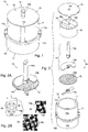
- a disgregating device of biological material MB such as for example the biological tissue illustrated schematically in Fig. 5 , made in accordance with the present invention, is denoted overall by 10.
- the disgregating device 10 is particularly suitable and advantageous for preparing cell suspensions and setting up tissue micrografts, understanding a tissue micrograft, in line with what has already been explained previously, to be a cell suspension or a set of cells, in an extracellular matrix, of subclinical size and therefore not visible to the naked eye but only with the aid of a microscope.
- disgregating device 10 of biological material MB is composed of the following parts:
- the bladed rotor 14, rotating, included in the disgregating device 10, in turn is constituted by:
- the cylindrical outer body 11, included in the disgregating device 10 of the invention, is in turn associated with a secondary internal body 16, defining the upper loading chamber 12a, and is constituted by an upper portion 11a which defines a seat 11' which houses this secondary inner body 16 and a lower portion 11b that defines the lower collecting chamber 12b, wherein the perforated disgregating grid 13 is interposed between this secondary inner body 16, housed in the respective seat 11' defined by the upper portion 11a of the outer body 11, and the lower portion 11b, defining the lower collecting chamber 12b, of the outer body 11.
- the outer body 11 of the disgregating device 10 defines a through hole 11c which extends in vertical direction in the external cylindrical wall of the same outer body 11, between an upper edge of the upper portion 11a and the base of the lower collecting chamber 12b, corresponding to the lower portion 11b, so as to traverse these two portions 11a and 11b of the outer body 11.
- this vertical through hole 11c is suitable for placing in communication the exterior of the disgregating device 10 with the lower collecting chamber 12b, in order to allow the extraction from the same lower collecting chamber 12b of the disgregated biological material MB', as described in greater detail here below.
- the secondary internal body 16, associated with the outer body 11, in turn has a portion 16a defining a hole 16b which houses rotatably the shaft 14 of the bladed rotor 14, and is moreover attached to the upper portion 11a of the outer body 11 so as not to rotate and thus avoid any rotation of the perforated disgregating grid 13, interposed between the same secondary internal body 16 and the lower portion 11b, defining the lower collecting chamber 12b, of the outer body 11, when the bladed rotor 14 rotates in the inner chamber 12 to cause the disgregation of the biological material MB, as illustrated more clearly here below when describing the working of the disgregating device 10.
- the outer body 11, the cover 15, the secondary internal body 16 and the shaft 14a of the bladed rotor 14 are in biocompatible plastic material, while the perforated disgregating grid 13 and the distributing blade 14b of the bladed rotor 14 are in stainless steel, of the type suitable for the manufacture of instruments for surgical uses.
- microholes 13a which characterise and are formed in the disgregating grid 13, in particular in relation to their specific dimensions and configuration, these microholes 13a will now be described in a detailed manner, also as regards the respective manufacturing process.
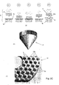
- the microholes 13a of the perforated disgregating grid or plate 13 have size or a diameter, denoted by D in Fig. 2B , which is comprised between 70 and 80 ⁇ m, and more preferably have a size or diameter D of about 75 ⁇ m.
- tissue micrografts and prepare cell suspensions usable for various purposes and applications, for example as specimens and samples simply to be analysed for research purposes or usable in the diagnosis and therapy of certain pathologies, which maintain integral and unaltered the features, functions and cell viability of the original biological material MB, in this way avoiding the use of chemical reagents for preparing these tissue micrografts and cell suspensions, as instead is often necessary in the prior art.
- the microholes 13a of the disgregating grid or plate 13 are formed by means of a special moulding and forming process, by means of a mould S of the die-punch type, of a sheet or a leaf or a metal strip, in particular made up of a strip of AISI 316L stainless steel.
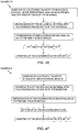
- Fig. 2C shows schematically, in the respective section (a), the various steps of a process of manufacturing and forming by moulding of the microholes 13a of the disgregating grid 13 included in a disgregating device 10 not according to the invention.
- the punch P used in this first embodiment of the process of manufacturing and forming of the microholes 13a has a conical and pointed configuration, as clearly shown in Fig. 2C - section (b).
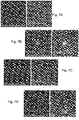
- Fig. 2C - section (c) shows a photographic image of a portion of the disgregating grid 13, obtained with the process of manufacturing by moulding schematised in section (a) of the same Fig. 2C , wherein this photographic image clearly highlights the configuration of the microholes 13a and in particular how each of them has an orifice with sharp edge B, as the effect of the tearing or of the breakage, caused by the process of manufacturing by moulding, of the material of the original strip N.
- the orifice that is created through tearing, or breakage of the material of the strip N, at the top of the respective drawn area, by the action of the conical punch P in co-operation with the die M, is not regular but has a sharp jagged edge, through the effect of the breakage of the material of the strip N.
- the average size or the average diameter of the microholes 13a generated in this way by the breakage of the material of the strip N can vary from a minimum of 50 microns to a maximum of 200 microns.
- Fig. 2D in turn shows schematically, in the respective section (a), the various steps of an embodiment of a process of manufacturing and forming by moulding of the microholes 13a of the disgregating grid 13 included in the disgregating device 10 of biological material of the invention.
- the process of manufacturing by moulding of the microholes 13a differs from that of the process not according to the invention, described previously with reference to Fig. 2C , in that the punch P has a polygonal configuration, as clearly shown in Fig. 2D - section (b), instead of conical.
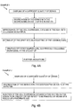
- the process of manufacturing by moulding of the microholes 13a comprises the following steps 01-05 illustrated in Fig. 2D - section (a) with the aid of arrows:
- Fig. 2D - section (c) shows a photographic image of a portion of the disgregating grid 13, obtained with the process of manufacturing by moulding schematised in section (a) of the same Fig. 2D and in accordance with the embodiment, wherein this photographic image clearly highlights the configuration of the microholes 13a and in particular how the orifice, defined by each of them, has a sharp edge B, as the effect of the tearing or of the breakage, caused by the process of manufacturing by moulding, of the material of the original strip N.
- microholes 13a each one exhibiting a sharp edge characterised by several sharp tips, in turn corresponding in number to that of the sides of the polygonal configuration of the punch P.
- each microhole 13a of the disgregating grid 13, constituting, together with the distributing blade 14b, the working structure of the disgregating device 10, are obtained with a process of moulding of the punch-die type which causes the breakage of the material of a sheet of stainless steel, so that through the effect of this breakage each microhole 13a has a respective irregular edge having sharp features, in particular defining a plurality of microblades.
- the microholes 13a can have a hexagonal shape as shown in Fig. 2B , in particular obtained using a hexagonal punch in the process of manufacturing illustrated in Fig. 2D .
- FIG. 2B shows in detail, with the aid of some photographic images obtained from a prototype of the disgregating device 10 of the invention, both a single hole 13a and a group of holes 13a which are formed in the disgregating grid 13, wherein the microblades which are associated with the sides of each hexagonal hole 13a are denoted by 13a'.
- FIG. 2E shows schematically, in the respective section (a), the various phases of a process of manufacturing and forming by moulding of the microholes 13a of the disgregating grid 13 included in the disgregating device 10 of biological material not according to the invention.
- the process of manufacturing by moulding of the microholes 13a differs from those of the first process not according to the invention and of the embodiment according to the invention, described previously with reference to Fig. 2C and 2D , in that the punch P, used in the process, has at the tip a rounded and not pointed configuration, so that the punch P is configured so as to deform and draw only the material of the strip N, but without causing the tearing and the fracture thereof, and moreover in that the orifice of the final microhole 13a is obtained, instead of by tearing and fracture of the material of the strip N, by means of a laser (light amplification by stimulated emission of radiation) source.
- a laser light amplification by stimulated emission of radiation
- the process of manufacturing of the microholes 13a comprises the following steps 01-05 illustrated in Fig. 2E - section (a) with the aid of arrows:
- Fig. 2E - sections (b) and (c) shows two photographic images of a portion of the disgregating grid 13 which is obtained with the process of manufacturing, schematised in section (a) of the same Fig. 2E , in accordance with this process and using a source of laser light, wherein these photographic images highlight and show in detail the apertures or the orifices formed by means of the source of laser light.
- the orifice which is created and obtained in this way with the laser, in the interior and in the central region of the zone drawn by means of the punch P, is particularly precise, and that this laser technique allows the orifice to be made with dimensions as required, in the particular in the range of 50 - 70 ⁇ m (microns) with a tolerance of ⁇ 5 ⁇ m (microns).
- the cut, made in this way by the laser, in turn appropriately calibrated for the type of cut required in order to form the orifice, has particularly sharp edges.
- the disgregating device 10 of the invention was specifically designed to shred and disgregate finely a biological material in order to obtain therefrom a cell suspension or a tissue micrograft and can be operated in the following way.
- This physiological solution has the function of performing an action of lubrication during the entire process of disgregation of the biological material and, also and above all, that of operating as a means of recovering the disgregated biological material obtained at the end of the disgregation process.
- the sample i.e. the biological material MB to be disgregated
- the sample is loaded into the upper loading chamber 12a, in turn in such dimensions as to allow the distributing blade 14b to surmount this biological material MB in the initial phase of the disgregation process.
- the motor is actuated so as to drive the rotation of the rotor 14, as indicated by arrows f1 in Fig. 3B , for a prefixed time, i.e. until the conclusion of the disgregation cycle.
- the distributing blade 14b of the bladed rotor 14, rotating distributes and brings the biological material MB loaded in the upper loading chamber 12a into contact with the microholes 13a formed in the disgregating grid 13, forcing it to pass through them, so that the biological material MB, passing through these microholes 13a and co-operating with the respective microblades, is appropriately disgregated.
- the scraper 14c rotating integrally with the distributing blade 14b, encourages the detachment of the disgregated biological material MB', after it has passed through the microholes 13a, from the lower surface of the disgregating grid 13, and its collection on the base of the collecting chamber 12b, as schematised with dotted and dashed line and indicated by arrows f2 in Fig. 3B .
- the bladed rotor 14 can be made to rotate at a speed of approximately 80 rpm, applying moreover thereon an appropriate torque, for example of 25 Nw*cm, in order to overcome the usual mechanical resistances which oppose this rotation, and therefore cause the passage of the biological material through the grid 14 and its consequent disaggregation.
- a syringe is inserted, of the type without needle, inside the hole 11c which extends vertically in the wall of the cylindrical outer body 11, and the cell suspension or the disgregated biological material MB', obtained in this way, is aspirated from the lower collecting chamber 12b, as indicated schematically by arrows f3 in Fig. 3B .
- the biological material MB is initially driven and brought into contact with the disgregating grid 13 by the distributing blade 14b which surmounts the biological material MB inside the loading chamber 12a.
- the physiological solution already contained in the loading chamber 12a, is enriched with cells.
- the bladed rotor 14 while it rotates, performs the dual function of rotating the biological material and of moving the physiological solution so as to mix them.
- the distributing blade 14b of the bladed rotor 14 being appropriately shaped along a helical profile, ensures that, during the phase of disgregation of the biological material MB, the physiological solution, contained in the loading chamber 12a, washes continuously the surface of the disgregating grid 13.
- This continuous distribution of the physiological solution in contact with the perforated disgregating grid 13 in turn is such as to continuously clean the respective holes 13a and therefore allow the free passage through them of the cells, so as to avoid overheating and/or burning of the tissues and of the cells or other disadvantages which could alter the features of the original biological material MB, during the sliding of the distributing blade 14b on the disgregating grid 13.
- FIG. 5A shows schematically a cell suspension obtained through disgregation of an original biological material MB, as shown in Fig. 5 , using the disgregating device 10 of the invention.
- Fig. 5A in the cell suspension obtained in this way the disgregated biological material, denoted by MB', conserves intact its features and functions, and in particular the cells CEL maintain their original form, just as the fragments of matrix MAT and the growth factors FC, indicative of the viability of the cells CEL, do not present alterations and modifications to the detriment of the viability and of the capacity for developing and reacting with the external conditions, represented with arrows in Fig. 5A , of the same cells CEL.
- each single cell CEL conserves intact all those organic and inorganic factors which involve it and constitute its biological niche and therefore determine the function and the capacities thereof, such as in particular that of developing.
- the cell matrix is also subject to alterations and modifications so that, in the final cell suspension obtained by disgregating the original biological material, the single cells are found to be free from all those organic and inorganic factors which involve them, in their biological niche, and determine the function and the capacities thereof.
- disgregating device 10 of the invention is particularly suitable and advantageous for preparing tissue micrografts and cell suspensions to be used for various purposes and in multiple applications, both typically medical and not, for example for the simple analysis in the laboratory of samples or for diagnostic or therapeutic or cosmetic purposes or others again, as ascertained by thorough and extensive tests and experiments.
- the graft site is prepared, i.e. with the bloodletting of the lesion or wound to be treated.
- the biocomplex obtained previously is grafted in the site, made up of the cell suspension and the biomaterial, and then a common medication is performed.
- a sufficient quantity of dermis for performing the treatment is taken initially from an uninjured area of the human body.
- the cell suspension is injected under the lesion to be treated or the defect to be removed, which can be wrinkles, psoriasis, scleroderma, vitiligo, ulcer, keloid, minus, etc., with a needle of adequate size.
- a sufficient quantity of biological material (bone, periosteum or dental pulp) is taken initially without drawing blood and without overheating it, and it is then fragmented and processed via the proposed disgregating device 10, so as to obtain and prepare the respective cell suspension.
- a phase of impregnation of the biomaterial is provided, i.e. of the cell suspension, in the prosthesis/plate to be applied, so as to obtain the biocomplex.
- the receiving site is set up (bone defect of various nature, fracture, acceptor site of prostheses such as for example hip prosthesis, knee, dental implants, etc.) that is a surgical access is carried out and, after having set it up, the already prepared biocomplex is grafted in the receiving site.
- Impregnation is then carried out of the biomaterial obtained for disgregation, thus preparing the biocomplex.
- the receiving site is then set up.
- the biocomplex obtained is grafted.
- the biological material after having been initially taken in a sufficient quantity from a healthy zone of the body of an animal (bone, periosteum, skin, muscle) without drawing blood and without overheating it, is fragmented and processed by means of the disgregating device 10, proposed.
- Impregnation is then carried out of the biomaterial obtained for disgregation, thus preparing the biocomplex.
- the receiving site is then set up.
- the biocomplex previously prepared is grafted.
- Impregnation is then carried out of the biomaterial obtained for disgregation, so as to prepare the biocomplex.
- the receiving site is then set up.
- the patient is then referred for subsequent checks.
- the disgregating device 10 and the relative products, i.e. the cell suspensions and the samples obtained with this device for disgregation of an original biological material, were the subject of numerous and in-depth experimental checks and tests aimed at collecting useful data and at confirming the innovative features and the advantages of the present invention.
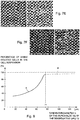
- Figs. 7A-7F show some examples of slides and samples which have been analysed and examined as part of these tests and therefore can be clearly understood and interpreted by skilled persons, wherein these samples, the subject of analysis and study, were obtained from a disgregated tissue by means of the disgregating device 10 of the invention of biological material.
- the samples analysed, derived from the disgregated original tissue clearly have two different populations of cells, i.e. a first population with an elongated shape and a second population with a rhomboid shape, larger.
- FIG. 8 More particularly the qualitative diagram of Fig. 8 , which summarises and condenses the numerous tests performed to ascertain the features and the advantages of the present invention, clearly shows that, in the cell suspension obtained by means of the disgregating device 10 of the invention, the percentage of viable isolated cells and of the respective growth factors reaches its maximum and optimal value when the holes 13a of the disgregating grid 13 have size or a diameter of around 75 microns.
- this percentage of the viable isolated cells is substantially lower than the maximum value, as shown by the portion A with continuous line of the diagram of Fig. 8 .
- the disgregating device 10 allows the preparing and obtaining of samples of biological tissue and more generally of biological material, obtained through disgregation of a tissue that is of an original biological material, wherein advantageously the samples obtained and in particular the respective cells conserve intact and unaltered the features, the functions and the cell viability of the tissue and of the original biological material and therefore are not altered by the phase of disgregation whereto they have been subjected, with the further advantage that the samples obtained, being intact and conserving their original cell viability, are suitable to be analysed directly without resorting to the aid of chemical reagents.
- the disgregating device 10 of the present invention constitutes a significant improvement and an important innovation with respect to the prior art, in particular constituted by the shredding device described in the patent US 5,731,199 , both in the method of manufacture of the parts which are essential for the working of the disgregating device and as regards its use and its potential applications, and in particular allows a considerable expansion of the field of application of the disgregating device with respect to that allowed by the device known from the patent US 5,731,199 .
- the blades of the bladed rotor 14 can be more than one, i.e. can be four or six placed symmetrically around the tip area of the shaft 14a.
- the disgregating device 10 of the invention can be associated with a magnetic element having the function of appropriately controlling the pressure with which the bladed rotor 14 and the disgregating grid 13 co-operate one with the other in order to disgregate the biological material.
- the disgregating device 10 is provided with a magnetic element, denoted by MAG and constituted in particular by a permanent neodymium magnet, which is glued to the base of the tray or lower collecting chamber 12b of the disgregating device 10.
- a magnetic element denoted by MAG and constituted in particular by a permanent neodymium magnet, which is glued to the base of the tray or lower collecting chamber 12b of the disgregating device 10.
- the disgregating device 10 is provided in combination with an additional support base BA and the magnetic element MAG is attached on the base of a seat S which is formed in this additional support base BA and has the function of receiving and housing stably during use the disgregating device 10.
- This magnet MAG performs the action, in both embodiments 10-1 and 10-2, of attracting the helical blade 14b of the bladed rotor 14 with a pre-established load, so as to control the pressure applied by the same bladed rotor 14b on the disgregating grid 13 and in particular avoid an excessive value of this pressure.
- the two parts which in the disgregating device 19 co-operate in contact and in ratio of pressure one with the other to disgregate the biological material i.e. the helical blade 14b of the bladed rotor 14 and the disgregating grid 13, are made of up of steels exhibiting different allotropic phases, austenitic or martensitic, so that the disgregating grid 13, made for example with 316L stainless steel therefore austenitic steel, is amagnetic and therefore insensitive to the magnetic field generated by the magnet MAG, whereas instead the helical blade 14b, made with martensitic steel, is sensitive to the magnetic field generated by the magnet MAG and is therefore pushed with a controlled pressure or force against the disgregating grid 13.
- the permanent magnet MAG is dimensioned and selected in terms of power and capacity of attraction in such a way that the pressure applied by the helical blade 14b against the disgregating grid 13 is adequate for obtaining a correct disgregation of the biological material.
- these variants 10-1 and 10-2 of the disgregating device of the invention have the advantage of keeping effectively under control the pressure applied by the helical blade or rotor 14b against the disgregating grid 13, so as to obtain an optimal disgregation of the biological material and therefore prevent and remedy some disadvantages which can occur in known disgregating devices, such as for example that described by the patent US 5,731,199 , in which this control is lacking.
- the disgregating device 10 of biological material can be advantageously connected, with the aid of an appropriate adapter, to a usual surgical wand or electric motor, sterile, already present in the operating theatre, so as to allow use of the disgregating device 10 of the invention directly in the operating theatre.
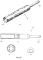
- Fig. 3D shows this adapter, denoted in general by 20, which allows in fact the connection of the disgregating device 10 of the invention to a common surgical motor or manipulator, included in the supply of sterile devices and instruments usually present in the operating theatre.
- the adapter 20 has an elongated configuration with a first end 20a apt to connect the adapter 20, on one side, to the shaft 14a, projecting, of the disgregating device 10, and a second opposite end 20b, appropriately shaped, apt to connect the adapter 20, on the other side, to the surgical wand, already present in the operating theatre.
- this adapter 20 is connected, in the operating theatre, on the one side to the projecting shaft 14a of the disgregating device 10 and on another side to the surgical wand.
- the surgical wand is then actuated so as to rotate at an appropriate speed, in particular 80 rpm, and applying an appropriate torque, for example of 25/Nw*cm, as already indicated previously, the bladed rotor 14 of the disgregating device 10 and consequently cause the disgregation of the biological material, already taken from the patient being treated in the operating theatre and previously introduced into the disgregating device 10.
- the biological material taken from the patient it is possible to prepare the disgregated biological material, for example in the form of a tissue micrograft, to be reinserted in the body of the patient who is being treated in the operating theatre.
- the disgregating device 10 of the invention thanks to the adapter 20 described previously, allows innovative performances and results which go far beyond those permitted by the prior art, for example by the shredder device of biological material described by the patent US 5,731,199 already cited several times previously, so as to constitute a valid alternative to the known systems currently in use.
- the disgregating device 10 of the invention used in combination with this adapter 20 which allows the connection thereof with a sterile surgical wand, already present in the operating theatre, is no longer configured as a simple disgregating device of biological material, such as that described by the patent US 5,731,199 , but becomes and can be compared, at least functionally, with a surgical instrument which can be directly used in the operating theatre, i.e. to a sterile and single-use microscalpel, constituted by a plurality of microblades, for example 600, supposing that the disgregating grid 13 of the device 10 has 100 microholes or hexagonal pores, i.e.
- microscalpel 100 microholes each one defining 6 microblades, therefore a total in fact of 600 microblades, wherein this microscalpel can be used to cut and disgregate the tissues in a few minutes in order to obtain, directly in the operating theatre and without further processes, the tissue fragments of calibrated dimensions which are required for the patients being treated in the operating theatre.
- the disgregating device 10 of the invention could be also defined as a microscalpel for mini-invasive microsurgery.
- the disgregating device 10 of the invention by connecting via the adapter 20 the disgregating device 10 of the invention with a surgical manipulator included in the supply of instruments and devices, sterile, already present in the operating theatre, it is possible to make available and to use the device 10 directly in the operating theatre, conserving the sterility and the efficiency of the system and at the same time observing the law.
- the disgregating device of the invention becomes also an essential part of an innovative instrumental clinical and surgical procedure, for the regeneration of tissues in the operating theatre, apt to observe the conditions of sterility, procedure which was not instead possible to perform before with the instruments offered by the prior art, in particular with the device described by the patent US 5,731,199 .
- the disgregating device 10 is configured in fact and can be rightfully compared to a surgical mill or miniscalpel provided with a plurality of microblades, for example in a number of 600, in order to cut and fragment the tissue of the patient to be treated in the operating theatre.
Landscapes
- Engineering & Computer Science (AREA)
- Food Science & Technology (AREA)
- Health & Medical Sciences (AREA)
- Life Sciences & Earth Sciences (AREA)
- Chemical & Material Sciences (AREA)
- Wood Science & Technology (AREA)
- Zoology (AREA)
- Organic Chemistry (AREA)
- Bioinformatics & Cheminformatics (AREA)
- Biomedical Technology (AREA)
- Genetics & Genomics (AREA)
- Biochemistry (AREA)
- General Health & Medical Sciences (AREA)
- Biotechnology (AREA)
- Sustainable Development (AREA)
- General Engineering & Computer Science (AREA)
- Microbiology (AREA)
- Molecular Biology (AREA)
- Mechanical Engineering (AREA)
- Immunology (AREA)
- Analytical Chemistry (AREA)
- General Physics & Mathematics (AREA)
- Physics & Mathematics (AREA)
- Pathology (AREA)
- Apparatus Associated With Microorganisms And Enzymes (AREA)
- Sampling And Sample Adjustment (AREA)
- Materials For Medical Uses (AREA)
- Investigating Or Analysing Biological Materials (AREA)
- Immobilizing And Processing Of Enzymes And Microorganisms (AREA)
- Micro-Organisms Or Cultivation Processes Thereof (AREA)
- Cosmetics (AREA)
- Optical Measuring Cells (AREA)
- Prostheses (AREA)
Claims (12)
- Zerlegungsvorrichtung (10) zum Zerlegen von biologischem Material, insbesondere zur Präparation von Zellsuspensionen oder Gewebe-Mikrografts oder Mikrofragmenten von Gewebe, mit:- einem hohlen äußeren Körper (11), der eine innere Kammer (12) festlegt;- einer perforierten Platte oder einem Zerlegungsgitter (13), fest und mit mehreren Mikrolöchern (13a), die mit scharfen Kanten versehen sind, wobei das Zerlegungsgitter in der inneren Kammer (12) transversal aufgenommen ist, so dass es eine obere Beladungskammer (12a), die zur Beladung mit dem biologischen Material (MB), das zu zerlegen ist, angepasst ist, und eine untere Sammelkammer (12b), die zum Sammeln des biologischen Materials (MB'), das zerlegt worden ist, angepasst ist, festlegt; und- einem Blattrotor (14), der sich in der inneren Kammer (12) dreht, wobei der sich drehende Blattrotor (14) angepasst ist zum Zusammenwirken mit dem festen Zerlegungsgitter (13) zum Zuführen des biologischen Materials (MB), das in der oberen Beladungskammer (12a) enthalten ist, zu den Mikrolöchern (13a) mit scharfen Kanten des Zerlegungsgitters (13) und in Kontakt bringen mit denselben und somit Bewirken der Zerlegung des biologischen Materials (MB), während es durch die Mikrolöcher (13a) geht;dadurch gekennzeichnet, dass die Mikrolöcher (13a) des perforierten Zerlegungsgitters (13) Dimensionen oder einen Durchmesser (D) zwischen 70 und 80 µm, bevorzugt Dimensionen oder einen Durchmesser (D) von etwa 75 µm, aufweisen,
dass die Mikrolöcher (13a) des Zerlegungsgitters (13) mittels eines Prozesses zur Herstellung durch Formen mit Stempel und Matrize (M, P) unter Verwendung eines Stempels (P) mit einer polygonbasierten Pyramidenform ausgebildet werden,
dass der Stempel (P) und die entsprechende Matrize (M) derart ausgebildet sind, dass jedes der Mikrolöcher (13a) durch Brechen und Reißen des Materials eines Metallblechs (N) erhalten wird und durch dieses Brechen oder Reißen eine irreguläre scharfe Kante (B) aufweist, die mehrere scharfe Spitzen festlegt, und
dass der äußere Körper (11) ein Durchgangsloch (11c) festlegt, das sich im Wesentlichen vertikal zwischen einem oberen Rand des äußeren Körpers (11) und der Basis der Sammelkammer (12b) erstreckt, wobei das Durchgangsloch (11c) die Funktion zum Ermöglichen der Extraktion des zerlegten biologischen Materials (MB'), das in der Sammelkammer (12b) angesammelt ist, aufweist,
wobei die Zerlegungsvorrichtung (10) angepasst ist zum Präparieren von Zellsuspensionen und Herstellen von Gewebe-Mikrografts, die die Charakteristiken und die Zellviabilität des ursprünglichen, nicht zerlegten biologischen Materials erhalten, so dass die Verwendung von chemischen Reagenzien bei der Präparation dieser Zellsuspensionen und bei der Herstellung dieser Gewebe-Mikrografts vermieden wird. - Zerlegungsvorrichtung (10) nach Anspruch 1, bei der der Blattrotor (14) gebildet wird durch:- eine Welle (14a), die in der vertikalen Richtung angeordnet ist;- ein Verteilerblatt (14b), das einem unteren Ende der vertikalen Welle (14a) zugeordnet ist und eine gekrümmte Schraubenform aufweist; und- einen unteren Schaber (14c), der ebenfalls dem unteren Ende der vertikalen welle (14a) zugeordnet ist,bei der das feste Zerlegungsgitter (13) zwischen dem schraubenförmigen Verteilerblatt (14b) und dem unteren Schaber (14c), die beide dem unteren Ende der vertikalen Welle (14a) zugeordnet sind, angeordnet ist, wodurch der Blattrotor (14) über sein schraubenförmiges Verteilerblatt (14b) und seinen unteren Schaber (14c) durch Drehung jeweils mit einer oberen Fläche des Zerlegungsgitters (13), die der oberen Beladungskammer (12a) zugewandt ist, zum Verteilen des biologischen Materials (MB), das zu zerlegen ist, und in Kontakt bringen desselben mit den Mikrolöchern (13a) des Zerlegungsgitters (13) und mit einer unteren Fläche des Zerlegungsgitters (13), die der Sammelkammer (12b) zugewandt ist, zum Abschaben des zerlegten biologischen Materials (MB'), das aus den Mikrolöchern (13) des Zerlegungsgitters (13) kommt, und Befördern (f2) desselben in die Sammelkammer (12b) zusammenwirken kann.
- Zerlegungsvorrichtung (10) nach einem der vorhergehenden Ansprüche, bei der der äußere Körper (11) einem zweiten inneren Körper (16) zugeordnet ist, der die obere Beladungskammer (12a) festlegt und durch einen oberen Abschnitt (11a), der einen Sitz (11') festlegt, der den zweiten inneren Körper (16) aufnimmt, und einen unteren Abschnitt (11b), die die untere Sammelkammer (12b) festlegt, gebildet wird,
bei der das Zerlegungsgitter (13) zwischen dem zweiten inneren Körper (16), der in dem Sitz (11'), der durch den oberen Abschnitt (11a) festgelegt wird, aufgenommen ist, und dem unteren Abschnitt (11b) des äußeren Körpers (11), der die untere Sammelkammer (12b) festlegt, angeordnet ist und
bei der der zweite innere Körper (16) einen Tragsitz zum drehbar Tragen des Blattrotors (14), insbesondere der jeweiligen Welle (14a), ausgebildet ist und mit dem oberen Abschnitt (11a) des äußeren Körpers (11) so verbunden ist, dass er sich nicht dreht und so eine Drehung des Zerlegungsgitters (13), das zwischen dem zweiten inneren Körpers (16) und dem unteren Abschnitt (11b) des äußeren Körpers (11) angeordnet ist, vermeidet, wenn sich der Blattrotor (14) zum Bewirken der Zerlegung des biologischen Materials (MB) in der inneren Kammer (12) dreht. - Zerlegungsvorrichtung (10) nach einem der vorhergehenden Ansprüche, bei der jedes Mikroloch (13a) des Zerlegungsgitters (13) mit mehreren Blättern versehen ist und insbesondere eine hexagonale Form mit sechs Blättern, die jeweils einer Seite des Hexagons zugeordnet sind, aufweist.
- Zerlegungsvorrichtung (10) nach einem der vorhergehenden Ansprüche, ferner mit einer abnehmbaren Abdeckung (15) zum Abdecken der oberen Beladungskammer (12a), wobei der Blattrotor (14) sich durch ein Loch (15a), das in der Abdeckung (15) ausgebildet ist, erstreckt, wodurch der Blattrotor an einem jeweiligen oberen Ende teilweise von der Abdeckung (15) vorsteht, so dass die Verbindung des Blattrotors (14) mit einem geeigneten Motormittel, das zum Steuern seiner Drehung in der inneren Kammer (12) angepasst ist, ermöglicht wird.
- Zerlegungsvorrichtung (10) nach Anspruch 2, bei der der Schaber (14c) durch mehrere Schaufeln in Form eines Zapfens gebildet wird, insbesondere zwei, die einander gegenüberliegen und sich radial von dem unteren Ende der Welle (14a) des Blattrotors (14) erstrecken.
- Zerlegungsvorrichtung (10, 10-1; 10-2) nach einem der Ansprüche 1 bis 6, bei der die Zerlegungsvorrichtung (10) ein insbesondere durch einen Permanentmagneten gebildetes Magnetelement (MAG) aufweist, das zum Anziehen des schraubenförmigen Blatts (14b) des Blattrotors (14) mit einer voreingestellten Last zum Steuern des durch den Blattrotor (14b) auf das Zerlegungsgitter (13) aufgebrachten Drucks bei der Verwendung der Zerlegungsvorrichtung (10) angepasst ist.
- Zerlegungsvorrichtung (10, 10-1; 10-2) nach Anspruch 7, bei der das Magnetelement (MAG) an der Basis des Fachs oder der unteren Sammelkammer (12b) der Zerlegungsvorrichtung (10) angebracht ist.
- Zerlegungsvorrichtung (10, 10-1; 10-2) nach Anspruch 8, bei der das Magnetelement (MAG) an der Basis eines Sitzes (S), der in einer zusätzlichen Tragbasis (BA) ausgebildet ist und die Funktion zum Aufnehmen der Zerlegungsvorrichtung (10) während einer Verwendung aufweist, angebracht ist.
- Verfahren zur Herstellung einer Zerlegungsvorrichtung (10) zum Zerlegen von biologischem Material mit mindestens einer perforierten Platte oder einem Zerlegungsgitter (13) mit mehreren scharfen Mikrolöchern (13a), durch die das biologische Material zur Zerlegung hindurchgebracht wird,
wobei das Verfahren einen Schritt zum Formen, mittels einer Form (S) mit Stempel und Matrize, eines Ausgangsmetallblechs oder -streifens (N), insbesondere aus 316L-Edelstahl, zum Ausbilden der Mikrolöcher (13a) des Zerlegungsgitters (13) in dem Metallblech (N) aufweist;
wobei die Matrize (M) und der Stempel (P) der Form (S) derart ausgebildet sind, dass während der Formphase das Metallblech (N) so gezogen und gerissen wird, dass durch Reißen und Brechen des Metallblechs (N) die Mikrolöcher (13a) des Zerlegungsgitters (13) erhalten werden;
wobei der Stempel (P) der Form (S) eine polygonbasierte Pyramidenform aufweist, beispielsweise mit sechs Seiten, so dass die Mikrolöcher (13a) des Zerlegungsgitters (13), die durch Reißen und Brechen des ursprünglichen Metallstreifens (N) erhalten werden, jeweils eine mit Zacken versehene scharfe Kante mit mehreren Spitzen aufweisen, beispielsweise sechs, deren Anzahl den Seiten des Polygonstempels entspricht; und
wobei die Mikrolöcher (13a) des Zerlegungsgitters (13), die durch das Reißen des ursprünglichen Metallstreifens (N) erhalten werden, Dimensionen oder einen Durchmesser (D) zwischen 70 und 80 µm, bevorzugt Dimensionen oder einen Durchmesser (D) von etwa 75 µm, aufweisen. - Kombination aus einer Zerlegungsvorrichtung (10) nach einem der Ansprüche 1 bis 6 zur Präparation von Mikrofragmenten von Gewebe und einem Adapter (20), der zum Verbinden der Vorrichtung (10) mit einem üblichen chirurgischen Manipulator, der in dem Vorrat an Instrumenten und Vorrichtungen, die steril sind und normalerweise in einem Operationssaal vorhanden sind, enthalten ist, angepasst ist.
- Kombination nach Anspruch 11, bei der der Adapter (20) eine längliche Form mit einem Ende (20a), das zum Verbinden mit einer vorstehenden Welle (14a) des Blattrotors (14) ausgebildet ist, und einem gegenüberliegenden Ende (20b), das zum Verbinden mit dem chirurgischen Manipulator angepasst ist, aufweist.
Priority Applications (5)
| Application Number | Priority Date | Filing Date | Title |
|---|---|---|---|
| RS20200570A RS60360B1 (sr) | 2014-12-15 | 2015-12-14 | Uređaj za disgregaciju biološkog materijala i odgovarajući postupak proizvodnje i postupak za pripremu ćelijskih suspenzija i tkivnih mikrograftova |
| PL15828756T PL3233289T3 (pl) | 2014-12-15 | 2015-12-14 | Urządzenie do dezagregacji materiału biologicznego i odpowiadający sposób wytwarzania, i sposób przygotowywania zawiesin komórkowych i mikroprzeszczepów tkankowych |
| HRP20200806TT HRP20200806T1 (hr) | 2014-12-15 | 2015-12-14 | Uređaj za disgregaciju biološkog materijala i odgovarajući postupak proizvodnje i postupak za pripremu staničnih suspenzija i tkivnih mikrografova |
| SM20200311T SMT202000311T1 (it) | 2014-12-15 | 2015-12-14 | Dispositio disgregatore di materiale biologico e corrispondente metodo di fabbricazione e metodo per la preparazione di sospensioni cellulari e microinnesti tessutali |
| SI201531215T SI3233289T1 (sl) | 2014-12-15 | 2015-12-14 | Naprava za ločevanje biološkega materiala in pripadajoč postopek izdelave in postopek za pripravo celičnih suspenzij in tkivnih mikrograftov |
Applications Claiming Priority (2)
| Application Number | Priority Date | Filing Date | Title |
|---|---|---|---|
| ITMI20142143 | 2014-12-15 | ||
| PCT/IB2015/059571 WO2016097960A2 (en) | 2014-12-15 | 2015-12-14 | Disgregating device of biological material and corresponding manufacturing method and method for the preparation of cell suspensions and tissue micrografts |
Publications (2)
| Publication Number | Publication Date |
|---|---|
| EP3233289A2 EP3233289A2 (de) | 2017-10-25 |
| EP3233289B1 true EP3233289B1 (de) | 2020-03-25 |
Family
ID=52463058
Family Applications (1)
| Application Number | Title | Priority Date | Filing Date |
|---|---|---|---|
| EP15828756.5A Active EP3233289B1 (de) | 2014-12-15 | 2015-12-14 | Desaggregationsvorrichtung für biologisches material und zugehöriges herstellungsverfahren sowie verfahren zur herstellung von zellsuspensionen und gewebemikrotransplantaten |
Country Status (24)
| Country | Link |
|---|---|
| US (1) | US10857544B2 (de) |
| EP (1) | EP3233289B1 (de) |
| JP (1) | JP6817953B2 (de) |
| KR (2) | KR102503809B1 (de) |
| CN (1) | CN107107068B (de) |
| AU (1) | AU2015365508B2 (de) |
| BR (1) | BR112017012740B1 (de) |
| CA (1) | CA2970426C (de) |
| CY (1) | CY1122942T1 (de) |
| DK (1) | DK3233289T3 (de) |
| EA (1) | EA035048B1 (de) |
| ES (1) | ES2800908T3 (de) |
| HR (1) | HRP20200806T1 (de) |
| HU (1) | HUE051098T2 (de) |
| IL (2) | IL300579B1 (de) |
| LT (1) | LT3233289T (de) |
| MX (1) | MX387565B (de) |
| PL (1) | PL3233289T3 (de) |
| PT (1) | PT3233289T (de) |
| RS (1) | RS60360B1 (de) |
| SG (1) | SG11201704728YA (de) |
| SI (1) | SI3233289T1 (de) |
| SM (1) | SMT202000311T1 (de) |
| WO (1) | WO2016097960A2 (de) |
Cited By (1)
| Publication number | Priority date | Publication date | Assignee | Title |
|---|---|---|---|---|
| US20230280242A1 (en) * | 2020-08-04 | 2023-09-07 | Achilles Therapeutics Uk Limited | Disaggregation device |
Families Citing this family (37)
| Publication number | Priority date | Publication date | Assignee | Title |
|---|---|---|---|---|
| ES2647458B1 (es) * | 2016-06-21 | 2018-09-28 | Jose Miguel CASANOVA ROSELL | Sistema y método para regeneración capilar a base de microinjertos autólogos de células madre y su uso. |
| ES2652135B1 (es) * | 2016-07-29 | 2018-07-30 | José Miguel CASANOVA ROSELL | Sistema y método para regeneración muscular, tendinosa, cartilaginosa y ósea con microinjertos autólogos de células madre y su uso |
| CN108627370A (zh) * | 2017-03-20 | 2018-10-09 | 深圳华因康基因科技有限公司 | 乳浊液制备仪 |
| KR102051223B1 (ko) * | 2017-09-05 | 2019-12-03 | 이준석 | 생체조직 미세화 장치 |
| CN109759211B (zh) * | 2017-12-05 | 2021-09-28 | 微思行(北京)科技有限公司 | 全自动研磨仪 |
| EP3743507A1 (de) * | 2018-01-24 | 2020-12-02 | FRAUNHOFER-GESELLSCHAFT zur Förderung der angewandten Forschung e.V. | Vorrichtung und verfahren zur dissoziation von gewebe |
| WO2020032042A1 (ja) * | 2018-08-06 | 2020-02-13 | 日産化学株式会社 | 細胞塊を分割するためのデバイス、および、それを用いて細胞塊を分割する方法 |
| US20200072712A1 (en) * | 2018-08-29 | 2020-03-05 | Predictive Technology Group, Inc. | Tissue mincers, related systems, and related methods |
| WO2020101622A1 (en) * | 2018-11-12 | 2020-05-22 | T-Bi̇yoteknoloji̇ Laboratuvar Esteti̇k Medi̇kal Kozmeti̇k San Ti̇c Ltd Şti̇ | Blade - filter kit developed to be used for fat transfer |
| US10973472B2 (en) * | 2019-03-05 | 2021-04-13 | Siemens Healthcare Gmbh | Artificial intelligence-based material decomposition in medical imaging |
| KR102202861B1 (ko) | 2019-04-09 | 2021-01-18 | 이준석 | 스크린 교환 장치, 이를 포함하는 생체조직 미세화 시스템, 이를 이용하는 생체조직 미세화 방법 및 이와 관련된 생체조직으로부터 타겟 물질을 분리하는 방법 |
| US12247902B2 (en) | 2019-05-06 | 2025-03-11 | Tissuemill Technologies Llc | Atraumatically formed tissue compositions, devices and methods of preparation and treatment |
| US11033295B2 (en) | 2019-05-06 | 2021-06-15 | Tissuemill Technologies Llc | Atraumatically formed tissue composition, devices and methods of preparation and treatment |
| IT201900006854A1 (it) | 2019-05-15 | 2020-11-15 | Fidia Farm Spa | Dispositivo per disgregare materiale biologico e relativo metodo di disgregazione e preparazioni cellulari |
| CN110124821B (zh) * | 2019-05-18 | 2020-11-06 | 池州灵芝化建材料科技有限公司 | 一种原矿自动分目磨碎收集装置及使用方法 |
| WO2020246781A1 (ko) * | 2019-06-02 | 2020-12-10 | (주)카스 인 바이오 | 연질 생체 조직을 미립자화하는 방법 및 이의 방법으로 제조된 연질 생체 조직 미립자 이식편 |
| IT201900014106A1 (it) * | 2019-08-06 | 2019-11-06 | Armando Roggero | Dispositivo disgregatore e dissociatore polimerico di materiali biologici solidi per utilizzo medicale e chirurgico rigenerativo |
| CN110643495A (zh) * | 2019-10-31 | 2020-01-03 | 北京伟力新世纪科技发展股份有限公司 | 一种细胞悬浮液制备装置 |
| CN110919706A (zh) * | 2019-11-01 | 2020-03-27 | 上海蓓蕊医疗科技有限公司 | 一种细胞精密切割装置及其使用方法 |
| RU196578U1 (ru) * | 2020-01-13 | 2020-03-05 | Виктория Игоревна Кузьмина | Устройство для дезинтеграции биологического материала |
| WO2021146805A1 (en) * | 2020-01-20 | 2021-07-29 | Genetrack Biolabs Inc. | Methods and devices for mincing biological tissue |
| GB2587257B (en) | 2020-03-09 | 2021-09-15 | Alma Lasers Ltd | Lipoaspirate processing |
| AU2021251750A1 (en) | 2020-04-06 | 2022-11-03 | Giacomo LANZONI | Device and method for tissue processing |
| US20220025316A1 (en) | 2020-07-22 | 2022-01-27 | Prim Sigma Technologies, Inc. | Trituration devices for tissue disaggregation |
| FI20206060A1 (fi) | 2020-10-26 | 2022-04-27 | Epiheart Oy | Laite ja menetelmä kudoksen hajottamiseksi mekaanisesti mikrosiirteiksi sekä kudoksen hajottamisen yhteydessä käytettävä syötinpala |
| CN112500995A (zh) * | 2020-12-22 | 2021-03-16 | 北京金莎科技有限公司 | 一种自体细胞微架构疗法装置 |
| CN112892797B (zh) * | 2021-01-19 | 2021-12-10 | 钱小英 | 一种玻璃生产用残次品粉碎回收再利用装置 |
| US11879121B2 (en) | 2021-04-20 | 2024-01-23 | CisNovo | Tissue disaggregation system and methods |
| CN113176123B (zh) * | 2021-04-29 | 2025-08-05 | 深圳市瑞沃德生命科技股份有限公司 | 一种实验容器及生物样本制备装置 |
| CN113640088B (zh) * | 2021-10-19 | 2021-12-14 | 南通中智检测服务有限公司 | 一种用于食品检测的分体粉碎装置 |
| US20250288721A1 (en) | 2022-04-27 | 2025-09-18 | Jörg C. GERLACH | Tissue structure isolation using a micro-cutting device and uses of resulting micro-cubes of tissue |
| KR102595329B1 (ko) | 2022-05-09 | 2023-10-30 | 미라셀 주식회사 | 생체조직 분쇄장치 |
| IT202200022533A1 (it) * | 2022-11-03 | 2024-05-03 | Mirco Cavicchioli | Dispositivo attivatore di un materiale agglomerato e rispettivi kit e procedimento di selezione |
| US12180456B2 (en) | 2022-12-27 | 2024-12-31 | AVITA Medical Americas, LLC | Tissue healing |
| CN115888918B (zh) * | 2023-03-13 | 2023-09-01 | 济南市莱芜百味食品有限公司 | 一种口蘑粉碎装置 |
| KR102683103B1 (ko) * | 2023-11-30 | 2024-07-09 | 디에스메카 주식회사 | 비접촉식 생체시료 조직분리 챔버의 원격 통합관리 시스템 |
| KR20250108438A (ko) | 2024-01-08 | 2025-07-15 | 나수정 | 미세조직 이식장치 |
Citations (6)
| Publication number | Priority date | Publication date | Assignee | Title |
|---|---|---|---|---|
| US5172920A (en) | 1992-01-28 | 1992-12-22 | Diamond Manufacturing Co. | Composite material for gaskets |
| US5731199A (en) | 1993-09-28 | 1998-03-24 | Roggero; Gianmarco | Mechanical triturator for biological material |
| US6109156A (en) | 1996-08-08 | 2000-08-29 | Ngk Insulators, Ltd. | Punching apparatus and punch |
| WO2002088296A1 (en) * | 2001-04-26 | 2002-11-07 | Boston Biomedica, Inc. | Multichamber device and uses thereof for processing of biological samples |
| WO2014039697A1 (en) | 2012-09-06 | 2014-03-13 | The Gid Group, Inc. | Tissue processing apparatus and method for processing adipose tissue |
| WO2014153072A1 (en) | 2013-03-14 | 2014-09-25 | Avita Medical Ltd. | Systems and methods for tissue processing and preparation of cell suspension therefrom |
Family Cites Families (8)
| Publication number | Priority date | Publication date | Assignee | Title |
|---|---|---|---|---|
| DE3620598C2 (de) * | 1986-06-19 | 1997-08-14 | Schnell Maschfab Karl | Vorrichtung zum automatischen Verstellen des Schneidsatzes einer Fleischzerkleinerungsmaschine |
| DE3804339A1 (de) * | 1988-02-12 | 1988-11-03 | Edwin P Schmidt | Fleischauswurfmischer |
| JPH10258239A (ja) * | 1997-03-19 | 1998-09-29 | Ebara Corp | 切削型破砕機 |
| JP2002223960A (ja) * | 2001-02-05 | 2002-08-13 | Matsushita Electric Ind Co Ltd | 電動調理器 |
| DE60232267D1 (de) * | 2001-10-18 | 2009-06-18 | Kadant Black Clawson Inc | Extraktionsgrundplatte mit laser- oder wasserstrahlgeschnittenen öffnungen |
| JP3930300B2 (ja) * | 2001-11-20 | 2007-06-13 | 日本碍子株式会社 | 打抜同時積層用打抜金型 |
| DE10312605B4 (de) * | 2003-03-21 | 2005-02-03 | Oliver Haack | Einrichtung zum Trennen und Abfördern von Rohstoffen |
| EP2775928B1 (de) * | 2011-11-08 | 2019-02-20 | Auxocell Laboratories Inc. | Systeme und verfahren zur verarbeitung von zellen |
-
2015
- 2015-12-14 EP EP15828756.5A patent/EP3233289B1/de active Active
- 2015-12-14 MX MX2017007932A patent/MX387565B/es unknown
- 2015-12-14 LT LTEP15828756.5T patent/LT3233289T/lt unknown
- 2015-12-14 AU AU2015365508A patent/AU2015365508B2/en active Active
- 2015-12-14 KR KR1020177018538A patent/KR102503809B1/ko active Active
- 2015-12-14 SM SM20200311T patent/SMT202000311T1/it unknown
- 2015-12-14 US US15/535,978 patent/US10857544B2/en active Active
- 2015-12-14 ES ES15828756T patent/ES2800908T3/es active Active
- 2015-12-14 HR HRP20200806TT patent/HRP20200806T1/hr unknown
- 2015-12-14 WO PCT/IB2015/059571 patent/WO2016097960A2/en not_active Ceased
- 2015-12-14 PT PT158287565T patent/PT3233289T/pt unknown
- 2015-12-14 CA CA2970426A patent/CA2970426C/en active Active
- 2015-12-14 IL IL300579A patent/IL300579B1/en unknown
- 2015-12-14 PL PL15828756T patent/PL3233289T3/pl unknown
- 2015-12-14 RS RS20200570A patent/RS60360B1/sr unknown
- 2015-12-14 KR KR1020237006168A patent/KR102565995B1/ko active Active
- 2015-12-14 BR BR112017012740-7A patent/BR112017012740B1/pt active IP Right Grant
- 2015-12-14 EA EA201791192A patent/EA035048B1/ru unknown
- 2015-12-14 SG SG11201704728YA patent/SG11201704728YA/en unknown
- 2015-12-14 JP JP2017549864A patent/JP6817953B2/ja active Active
- 2015-12-14 HU HUE15828756A patent/HUE051098T2/hu unknown
- 2015-12-14 CN CN201580068658.9A patent/CN107107068B/zh active Active
- 2015-12-14 DK DK15828756.5T patent/DK3233289T3/da active
- 2015-12-14 SI SI201531215T patent/SI3233289T1/sl unknown
-
2017
- 2017-06-12 IL IL252851A patent/IL252851B2/en unknown
-
2020
- 2020-05-20 CY CY20201100459T patent/CY1122942T1/el unknown
Patent Citations (6)
| Publication number | Priority date | Publication date | Assignee | Title |
|---|---|---|---|---|
| US5172920A (en) | 1992-01-28 | 1992-12-22 | Diamond Manufacturing Co. | Composite material for gaskets |
| US5731199A (en) | 1993-09-28 | 1998-03-24 | Roggero; Gianmarco | Mechanical triturator for biological material |
| US6109156A (en) | 1996-08-08 | 2000-08-29 | Ngk Insulators, Ltd. | Punching apparatus and punch |
| WO2002088296A1 (en) * | 2001-04-26 | 2002-11-07 | Boston Biomedica, Inc. | Multichamber device and uses thereof for processing of biological samples |
| WO2014039697A1 (en) | 2012-09-06 | 2014-03-13 | The Gid Group, Inc. | Tissue processing apparatus and method for processing adipose tissue |
| WO2014153072A1 (en) | 2013-03-14 | 2014-09-25 | Avita Medical Ltd. | Systems and methods for tissue processing and preparation of cell suspension therefrom |
Non-Patent Citations (7)
| Title |
|---|
| A GRAZIANO, F CARINCI , S SCOLARO , R D’AQUINO: "Periodontal tissue generation using autologous dental ligament micro-grafts: case report with 6 months follow-up", ANNALS OF ORAL & MAXILLOFACIAL SURGERY, vol. 1, no. 2, 1 June 2013 (2013-06-01), pages 20, XP055760461 |
| ALTA-TECH CAMLOG: "Video RIGENERA. Ricerca e tecnologia per la rigenerazione dei tessuti umani", YOUTUBE, 11 April 2014 (2014-04-11), Retrieved from the Internet <URL:https://www.youtube.com/watch?v=-ixE9bQSemo> |
| ANONYMOUS: "Rigenera MACHINE FOR MEDICAL APPLICATIONS OF CLINICAL REGENERATION", HUMAN BRAIN WAVE SRL, January 2013 (2013-01-01), pages 18pp, XP055760456, Retrieved from the Internet <URL:https://manualzz.com/doc/7177909/ctsv-sr1---rigenera> |
| GIORGIO BRUNELLI, ALESSANDRO MOTRONI, ANTONIO GRAZIANO, RICCARDO D'AQUINO, ILARIA ZOLLINO, FRANCESCO CARINCI: "Sinus lift tissue engineering using autologous pulp micro-grafts: A case report of bone density evaluation", J INDIAN SOC PERIODONTOL, vol. 17, no. 5, September 2013 (2013-09-01), pages 644 - 647, XP055760469 |
| MARCELLO MONTANARO: "The biotechnology RIGENERA® for tissue micro-grafts in regenerative medicine", TIRIGENERA, 5 November 2017 (2017-11-05), pages 1 - 2, XP055760481 |
| RIGENERA HBW: "HBW Rigenera - Workshop I Torino - Parte 6/6", YOUTUBE, 12 March 2013 (2013-03-12), XP054981227, Retrieved from the Internet <URL:https://www.youtube.com/watch?v=Zx58kQLaOJY> |
| STEFANO MUMMOLO, LEONARDO MANCINI , VINCENZO QUINZI, RICCARDO D’AQUINO , GIUSEPPE MARZO AND ENRICO MARCHETTI: "Rigenera® Autologous Micrografts in Oral Regeneration: Clinical, Histological, and Radiographical Evaluations", APPL. SCI., vol. 10, 5084, 23 July 2020 (2020-07-23), pages 1 - 12, XP055760483 |
Cited By (1)
| Publication number | Priority date | Publication date | Assignee | Title |
|---|---|---|---|---|
| US20230280242A1 (en) * | 2020-08-04 | 2023-09-07 | Achilles Therapeutics Uk Limited | Disaggregation device |
Also Published As
Similar Documents
| Publication | Publication Date | Title |
|---|---|---|
| EP3233289B1 (de) | Desaggregationsvorrichtung für biologisches material und zugehöriges herstellungsverfahren sowie verfahren zur herstellung von zellsuspensionen und gewebemikrotransplantaten | |
| US20240225688A1 (en) | Atraumatically formed tissue compositions, devices and methods of preparation and treatment | |
| US20250180446A1 (en) | Atraumatically formed tissue compositions, devices and methods of preparation and treatment | |
| KR102521122B1 (ko) | 생체 시료의 조직 분리 장치 | |
| US12135262B2 (en) | Comminuting device of biological material and relative method for comminuting and cellular preparations | |
| KR102536424B1 (ko) | 비수술 일체형 생체 시료 포집 분리 및 정량 주입 시스템 | |
| HK1243672B (en) | Disgregating device of biological material and corresponding manufacturing method and method for the preparation of cell suspensions and tissue micrografts | |
| KR20150000878A (ko) | 진피 미세 기관을 채취, 변형 및 재이식하기 위한 방법 및 장치 | |
| KR20240076670A (ko) | 생체 시료 포집 분리 및 정량 주입 장치 | |
| EA042520B1 (ru) | Устройство для измельчения биологического материала и соответствующий способ измельчения и приготовления клеточных препаратов |
Legal Events
| Date | Code | Title | Description |
|---|---|---|---|
| STAA | Information on the status of an ep patent application or granted ep patent |
Free format text: STATUS: THE INTERNATIONAL PUBLICATION HAS BEEN MADE |
|
| PUAI | Public reference made under article 153(3) epc to a published international application that has entered the european phase |
Free format text: ORIGINAL CODE: 0009012 |
|
| STAA | Information on the status of an ep patent application or granted ep patent |
Free format text: STATUS: REQUEST FOR EXAMINATION WAS MADE |
|
| 17P | Request for examination filed |
Effective date: 20170529 |
|
| AK | Designated contracting states |
Kind code of ref document: A2 Designated state(s): AL AT BE BG CH CY CZ DE DK EE ES FI FR GB GR HR HU IE IS IT LI LT LU LV MC MK MT NL NO PL PT RO RS SE SI SK SM TR |
|
| AX | Request for extension of the european patent |
Extension state: BA ME |
|
| DAV | Request for validation of the european patent (deleted) | ||
| DAX | Request for extension of the european patent (deleted) | ||
| STAA | Information on the status of an ep patent application or granted ep patent |
Free format text: STATUS: EXAMINATION IS IN PROGRESS |
|
| 17Q | First examination report despatched |
Effective date: 20180608 |
|
| REG | Reference to a national code |
Ref country code: HK Ref legal event code: DE Ref document number: 1243672 Country of ref document: HK |
|
| GRAP | Despatch of communication of intention to grant a patent |
Free format text: ORIGINAL CODE: EPIDOSNIGR1 |
|
| STAA | Information on the status of an ep patent application or granted ep patent |
Free format text: STATUS: GRANT OF PATENT IS INTENDED |
|
| INTG | Intention to grant announced |
Effective date: 20200116 |
|
| GRAS | Grant fee paid |
Free format text: ORIGINAL CODE: EPIDOSNIGR3 |
|
| GRAA | (expected) grant |
Free format text: ORIGINAL CODE: 0009210 |
|
| STAA | Information on the status of an ep patent application or granted ep patent |
Free format text: STATUS: THE PATENT HAS BEEN GRANTED |
|
| AK | Designated contracting states |
Kind code of ref document: B1 Designated state(s): AL AT BE BG CH CY CZ DE DK EE ES FI FR GB GR HR HU IE IS IT LI LT LU LV MC MK MT NL NO PL PT RO RS SE SI SK SM TR |
|
| REG | Reference to a national code |
Ref country code: GB Ref legal event code: FG4D |
|
| REG | Reference to a national code |
Ref country code: AT Ref legal event code: REF Ref document number: 1247967 Country of ref document: AT Kind code of ref document: T Effective date: 20200415 Ref country code: IE Ref legal event code: FG4D |
|
| REG | Reference to a national code |
Ref country code: DE Ref legal event code: R096 Ref document number: 602015049544 Country of ref document: DE |
|
| REG | Reference to a national code |
Ref country code: HR Ref legal event code: TUEP Ref document number: P20200806T Country of ref document: HR |
|
| REG | Reference to a national code |
Ref country code: DK Ref legal event code: T3 Effective date: 20200520 Ref country code: FI Ref legal event code: FGE |
|
| REG | Reference to a national code |
Ref country code: CH Ref legal event code: NV Representative=s name: TR-IP CONSULTING LLC, CH |
|
| REG | Reference to a national code |
Ref country code: NO Ref legal event code: T2 Effective date: 20200325 |
|
| REG | Reference to a national code |
Ref country code: NL Ref legal event code: FP |
|
| REG | Reference to a national code |
Ref country code: SE Ref legal event code: TRGR |
|
| REG | Reference to a national code |
Ref country code: PT Ref legal event code: SC4A Ref document number: 3233289 Country of ref document: PT Date of ref document: 20200623 Kind code of ref document: T Free format text: AVAILABILITY OF NATIONAL TRANSLATION Effective date: 20200616 |
|
| REG | Reference to a national code |
Ref country code: GR Ref legal event code: EP Ref document number: 20200401422 Country of ref document: GR Effective date: 20200716 |
|
| REG | Reference to a national code |
Ref country code: SK Ref legal event code: T3 Ref document number: E 34295 Country of ref document: SK |
|
| REG | Reference to a national code |
Ref country code: EE Ref legal event code: FG4A Ref document number: E019307 Country of ref document: EE Effective date: 20200519 |
|
| REG | Reference to a national code |
Ref country code: HR Ref legal event code: T1PR Ref document number: P20200806 Country of ref document: HR |
|
| REG | Reference to a national code |
Ref country code: DE Ref legal event code: R026 Ref document number: 602015049544 Country of ref document: DE |
|
| PLBI | Opposition filed |
Free format text: ORIGINAL CODE: 0009260 |
|
| REG | Reference to a national code |
Ref country code: HR Ref legal event code: ODRP Ref document number: P20200806 Country of ref document: HR Payment date: 20201022 Year of fee payment: 6 |
|
| REG | Reference to a national code |
Ref country code: ES Ref legal event code: FG2A Ref document number: 2800908 Country of ref document: ES Kind code of ref document: T3 Effective date: 20210105 |
|
| REG | Reference to a national code |
Ref country code: FI Ref legal event code: MDE Opponent name: LADIVA FOOD EXPORT IMPORT NAK. TAA. GIDA INS. TRZ. YAT. SAN. TIC. LTD. STI |
|
| 26 | Opposition filed |
Opponent name: LADIVA FOOD EXPORT IMPORT NAK. TAA. GIDA INS. TRZ. YAT. SAN. TIC. LTD. STI Effective date: 20201201 |
|
| PLAX | Notice of opposition and request to file observation + time limit sent |
Free format text: ORIGINAL CODE: EPIDOSNOBS2 |
|
| REG | Reference to a national code |
Ref country code: HU Ref legal event code: AG4A Ref document number: E051098 Country of ref document: HU |
|
| PLBB | Reply of patent proprietor to notice(s) of opposition received |
Free format text: ORIGINAL CODE: EPIDOSNOBS3 |
|
| PGFP | Annual fee paid to national office [announced via postgrant information from national office to epo] |
Ref country code: MK Payment date: 20201120 Year of fee payment: 6 |
|
| REG | Reference to a national code |
Ref country code: HR Ref legal event code: ODRP Ref document number: P20200806 Country of ref document: HR Payment date: 20211129 Year of fee payment: 7 |
|
| PLAB | Opposition data, opponent's data or that of the opponent's representative modified |
Free format text: ORIGINAL CODE: 0009299OPPO |
|
| R26 | Opposition filed (corrected) |
Opponent name: LADIVA FOOD EXPORT IMPORT NAK. TAA. GIDA INS. TRZ. YAT. SAN. TIC. LTD. STI Effective date: 20201201 |
|
| REG | Reference to a national code |
Ref country code: DE Ref legal event code: R100 Ref document number: 602015049544 Country of ref document: DE |
|
| PLCK | Communication despatched that opposition was rejected |
Free format text: ORIGINAL CODE: EPIDOSNREJ1 |
|
| RDAE | Information deleted related to despatch of communication that patent is revoked |
Free format text: ORIGINAL CODE: EPIDOSDREV1 |
|
| REG | Reference to a national code |
Ref country code: AT Ref legal event code: UEP Ref document number: 1247967 Country of ref document: AT Kind code of ref document: T Effective date: 20200325 |
|
| PLBN | Opposition rejected |
Free format text: ORIGINAL CODE: 0009273 |
|
| STAA | Information on the status of an ep patent application or granted ep patent |
Free format text: STATUS: OPPOSITION REJECTED |
|
| 27O | Opposition rejected |
Effective date: 20220510 |
|
| REG | Reference to a national code |
Ref country code: FR Ref legal event code: PLFP Year of fee payment: 8 |
|
| REG | Reference to a national code |
Ref country code: HR Ref legal event code: ODRP Ref document number: P20200806 Country of ref document: HR Payment date: 20221025 Year of fee payment: 8 |
|
| P01 | Opt-out of the competence of the unified patent court (upc) registered |
Effective date: 20230524 |
|
| REG | Reference to a national code |
Ref country code: DE Ref legal event code: R082 Ref document number: 602015049544 Country of ref document: DE Representative=s name: ALPSPITZ IP ALLGAYER UND PARTNER PATENTANWAELT, DE |
|
| REG | Reference to a national code |
Ref country code: HR Ref legal event code: ODRP Ref document number: P20200806 Country of ref document: HR Payment date: 20240503 Year of fee payment: 9 |
|
| PGFP | Annual fee paid to national office [announced via postgrant information from national office to epo] |
Ref country code: PT Payment date: 20241205 Year of fee payment: 10 |
|
| REG | Reference to a national code |
Ref country code: HR Ref legal event code: ODRP Ref document number: P20200806 Country of ref document: HR Payment date: 20241023 Year of fee payment: 10 |
|
| PGFP | Annual fee paid to national office [announced via postgrant information from national office to epo] |
Ref country code: LT Payment date: 20241122 Year of fee payment: 10 |
|
| PGFP | Annual fee paid to national office [announced via postgrant information from national office to epo] |
Ref country code: MC Payment date: 20241226 Year of fee payment: 10 Ref country code: NO Payment date: 20241220 Year of fee payment: 10 |
|
| PGFP | Annual fee paid to national office [announced via postgrant information from national office to epo] |
Ref country code: DK Payment date: 20241224 Year of fee payment: 10 |
|
| PGFP | Annual fee paid to national office [announced via postgrant information from national office to epo] |
Ref country code: BE Payment date: 20241219 Year of fee payment: 10 Ref country code: PL Payment date: 20241023 Year of fee payment: 10 Ref country code: NL Payment date: 20241224 Year of fee payment: 10 Ref country code: GR Payment date: 20241223 Year of fee payment: 10 Ref country code: FI Payment date: 20241217 Year of fee payment: 10 Ref country code: LU Payment date: 20241223 Year of fee payment: 10 |
|
| PGFP | Annual fee paid to national office [announced via postgrant information from national office to epo] |
Ref country code: GB Payment date: 20241226 Year of fee payment: 10 |
|
| PGFP | Annual fee paid to national office [announced via postgrant information from national office to epo] |
Ref country code: BG Payment date: 20241203 Year of fee payment: 10 Ref country code: FR Payment date: 20241127 Year of fee payment: 10 |
|
| PGFP | Annual fee paid to national office [announced via postgrant information from national office to epo] |
Ref country code: EE Payment date: 20241023 Year of fee payment: 10 Ref country code: LV Payment date: 20241218 Year of fee payment: 10 |
|
| PGFP | Annual fee paid to national office [announced via postgrant information from national office to epo] |
Ref country code: HU Payment date: 20241223 Year of fee payment: 10 Ref country code: IS Payment date: 20241210 Year of fee payment: 10 Ref country code: AT Payment date: 20241218 Year of fee payment: 10 |
|
| PGFP | Annual fee paid to national office [announced via postgrant information from national office to epo] |
Ref country code: IE Payment date: 20241223 Year of fee payment: 10 Ref country code: CZ Payment date: 20241023 Year of fee payment: 10 Ref country code: HR Payment date: 20241023 Year of fee payment: 10 |
|
| PGFP | Annual fee paid to national office [announced via postgrant information from national office to epo] |
Ref country code: RO Payment date: 20241104 Year of fee payment: 10 Ref country code: SK Payment date: 20241210 Year of fee payment: 10 |
|
| PGFP | Annual fee paid to national office [announced via postgrant information from national office to epo] |
Ref country code: IT Payment date: 20241004 Year of fee payment: 10 Ref country code: RS Payment date: 20241023 Year of fee payment: 10 Ref country code: SM Payment date: 20241210 Year of fee payment: 10 |
|
| PGFP | Annual fee paid to national office [announced via postgrant information from national office to epo] |
Ref country code: SE Payment date: 20241218 Year of fee payment: 10 |
|
| PGFP | Annual fee paid to national office [announced via postgrant information from national office to epo] |
Ref country code: MT Payment date: 20241125 Year of fee payment: 10 |
|
| PGFP | Annual fee paid to national office [announced via postgrant information from national office to epo] |
Ref country code: TR Payment date: 20241209 Year of fee payment: 10 |
|
| PGFP | Annual fee paid to national office [announced via postgrant information from national office to epo] |
Ref country code: AL Payment date: 20241024 Year of fee payment: 10 |
|
| PGFP | Annual fee paid to national office [announced via postgrant information from national office to epo] |
Ref country code: SI Payment date: 20241205 Year of fee payment: 10 |
|
| PGFP | Annual fee paid to national office [announced via postgrant information from national office to epo] |
Ref country code: DE Payment date: 20241227 Year of fee payment: 10 |
|
| PGFP | Annual fee paid to national office [announced via postgrant information from national office to epo] |
Ref country code: ES Payment date: 20250102 Year of fee payment: 10 |
|
| PGFP | Annual fee paid to national office [announced via postgrant information from national office to epo] |
Ref country code: CH Payment date: 20250101 Year of fee payment: 10 |
|
| PGFP | Annual fee paid to national office [announced via postgrant information from national office to epo] |
Ref country code: CY Payment date: 20241202 Year of fee payment: 10 |
|
| REG | Reference to a national code |
Ref country code: CH Ref legal event code: R17 Free format text: ST27 STATUS EVENT CODE: U-0-0-R10-R17 (AS PROVIDED BY THE NATIONAL OFFICE) Effective date: 20251204 |