EP3229652B1 - Grillvorrichtung sowie kupplung und grillgutteller hierfür - Google Patents
Grillvorrichtung sowie kupplung und grillgutteller hierfür Download PDFInfo
- Publication number
- EP3229652B1 EP3229652B1 EP15830979.9A EP15830979A EP3229652B1 EP 3229652 B1 EP3229652 B1 EP 3229652B1 EP 15830979 A EP15830979 A EP 15830979A EP 3229652 B1 EP3229652 B1 EP 3229652B1
- Authority
- EP
- European Patent Office
- Prior art keywords
- grilled
- food
- grill
- grill device
- frame
- Prior art date
- Legal status (The legal status is an assumption and is not a legal conclusion. Google has not performed a legal analysis and makes no representation as to the accuracy of the status listed.)
- Not-in-force
Links
Images


Classifications
-
- A—HUMAN NECESSITIES
- A47—FURNITURE; DOMESTIC ARTICLES OR APPLIANCES; COFFEE MILLS; SPICE MILLS; SUCTION CLEANERS IN GENERAL
- A47J—KITCHEN EQUIPMENT; COFFEE MILLS; SPICE MILLS; APPARATUS FOR MAKING BEVERAGES
- A47J37/00—Baking; Roasting; Grilling; Frying
- A47J37/04—Roasting apparatus with movably-mounted food supports or with movable heating implements; Spits
- A47J37/043—Roasting apparatus with movably-mounted food supports or with movable heating implements; Spits with food supports rotating about a vertical axis
-
- A—HUMAN NECESSITIES
- A47—FURNITURE; DOMESTIC ARTICLES OR APPLIANCES; COFFEE MILLS; SPICE MILLS; SUCTION CLEANERS IN GENERAL
- A47J—KITCHEN EQUIPMENT; COFFEE MILLS; SPICE MILLS; APPARATUS FOR MAKING BEVERAGES
- A47J37/00—Baking; Roasting; Grilling; Frying
- A47J37/06—Roasters; Grills; Sandwich grills
- A47J37/0694—Broiling racks
Definitions
- the invention relates to a grill device for grilling food to be grilled.
- grilling devices for grilling grilled food which require additional fastening elements, such as screws, to secure individual elements, in particular the grill food support, in order to ensure a secure connection between the grill food support and the associated frame
- WO 03/022115 A2 describes a grill device.
- the disadvantage here is that the removal and attachment of the grilled food supports is time-consuming due to the additional fastening means. Furthermore, the material of the fastening means can be deformed by the heat in such a way that loosening is no longer possible or at least made more difficult.
- a grilled food plate is to be provided, which is designed for different types of grilled food.
- the invention relates to a grilling device for grilling grilled food comprising at least one frame, with at least one frame element and with at least one holding element, for example an upper holding element and / or a lower holding element, which is arranged at an upper end of the frame element, the grilling device around a vertical
- the longitudinal axis is designed to be rotatable. Furthermore, it can be equipped with at least one grilled food support element or be suitable for holding it.
- the grill device in the case of an upper holding element, can be suspended and / or, in the case of a lower holding element, upright along the vertical axis of rotation.
- a core idea of the invention is that the frame element is arranged eccentrically with respect to the vertical axis of rotation, so that the food to be grilled can be arranged centrally.
- the food to be grilled can be arranged lying down without having to be locked separately, for example skewered.
- the centric arrangement of the grilled item has the advantage that when it rotates around the vertical axis of rotation, it can have a substantially constant distance (depending, for example, on the shape of the grilled item) so that it can be cooked as evenly as possible over its circumference.
- the at least one grilled food support element has a first partial area which is equipped with an opening through which the frame element can be guided.
- the frame element has a non-rotationally symmetrical cross-section such that the grilled food support element and the frame element interact positively with respect to a plane in which the vertical longitudinal axis does not lie, for example a normal plane of the vertical longitudinal axis.
- the grilled food support element can only be moved in the direction of the vertical longitudinal axis, but not rotated in a direction orthogonal thereto.
- a non-rotationally symmetrical cross-section is advantageous with regard to the form fit, since with rotationally symmetrical cross-sections there is the risk of the grilled item carrier element being unintentionally displaced or slipping off.
- the longitudinal axis here is to be understood as the axis in which the grill device has its longest geometric extent.
- the longitudinal axis is preferably at the same time the central central axis of the grilling device.
- the vertical longitudinal axis can be aligned in the direction of gravity. By rotating the grill around a vertical longitudinal axis enables the food to be grilled evenly. It is therefore a vertical grill device.
- the grilled food support element has an asymmetrical weight distribution with respect to the opening, so that the grilled food support element and the frame element interact in a non-positive manner with respect to the vertical longitudinal axis, in particular by means of a clamp connection.
- the grilled food support element is brought into a position, for example due to gravity, in which the grill food support element is clamped to the frame element, whereby a frictional connection is achieved.
- This connection creates at least two contact points between the opening and the frame element.
- a non-positive connection along the vertical longitudinal axis, but preferably a positive connection in directions orthogonal thereto, between the grilled food support element and the frame element is advantageous since the grill food support element is to be pivoted together with the frame element. In this case, however, it should be ensured that the grilled food support element remains in the previously determined position during the rotation.
- the non-positive connection must be designed for the forces permanently occurring due to the continuous rotation, so that slipping is prevented, even if the contact surfaces are wetted with a substance with a lubricating effect, such as grease.
- the opening of the first partial region of the grilled food carrier has a length in a horizontal direction which is designed to be greater than the thickness of the frame element. This configuration ensures that the grilled food carrier can be guided smoothly over the frame element without tilting or jamming prematurely.
- the first partial area of the grilled food carrier has an inclination with respect to the normal plane in a position of the form-fitting connection.
- the first sub-area is therefore not aligned horizontally, but is inclined to produce a clamp connection. A secure connection is achieved by jamming in this way.
- the grilled food support element preferably has a second partial area which is designed to receive the grilled food itself or at least to receive a grilled food plate.
- the second sub-area can be designed, for example, directly as a grilled food plate which can directly accommodate the grilled food.
- the second partial area is preferably formed, for example, by a receiving device such as two struts, which can accommodate a separate grilled food plate.
- the second sub-area has a length in a horizontal direction pointing away from the frame element which is at least three times as great as the length of the first sub-area in this direction.
- the asymmetrical weight distribution is favored by the different size ratios.
- a greater length of the second partial area enables a material weight that is sufficient to provide sufficient static friction of an inner area of the opening on the frame element so that the grilled item carrier element remains fixed in its position on the frame element.
- a greater length of the second sub-area also enables a second sub-area which is large enough to accommodate a correspondingly large item to be grilled. It is advantageous for the shape of the second partial area to have a shape that is modeled on a plate, for example.
- the shape of the second sub-area is not restricted to this. It is conceivable that the first and second partial areas together have approximately the shape of a tongue, which widens starting from the first partial area and then converges again in a round shape. In this way, good retention on the frame element with a surface that is advantageous for grilled food can be ensured at the same time. In this way, it is also advantageous to remove the grilled food or to equip it with grilled food, since a receiving space for the grilled food is only covered by a frame element and the grilled food is accessible from all sides in a 360 ° range.
- the at least one grilled food support element is preferably designed with an essentially L-shaped section.
- L-shaped is to be understood as meaning all sections which consist of two subsections which are at an angle to one another with a square or rounded connecting piece.
- the second partial area preferably extends in a position of a form-fitting connection between the grilled food support element and the frame element essentially in a horizontal direction. Such a horizontal alignment is necessary so that the grilled food, which is located on the second sub-area, is prevented from slipping off.
- the frame element particularly preferably has a further holding element on the underside of the frame element and / or a guide in the normal plane.
- a guide is particularly advantageous in this area in order to prevent the frame from swinging during rotation.
- the frame element is produced by drawing and has a curved area.
- the profile tapers in the curved area.
- the tapering occurs particularly preferably on the outside of the profile, that is to say in the region of the curvature which has the largest radius of curvature.
- a roller bearing is arranged above the upper holding element in the direction of the vertical longitudinal axis. A part of the upper holding element extends upwards in the direction of the vertical longitudinal axis and is guided through the roller bearing.
- the part of the upper holding element which is guided through the roller bearing preferably has at least one support surface for the support of the holding element on the roller bearing.
- This bearing surface can rest on the inner ring of the roller bearing or be attached to it. This offers the advantage that the weight of the frame is borne by the bearing, which leads to a reduced load on the drive.
- the grilling device preferably comprises a coupling with a piston and a cylinder for transmitting a rotational movement to a frame of a grilling device.
- the coupling between piston and cylinder is a force-locking coupling.
- the frictional coupling is particularly preferably a slip coupling.
- the piston and the cylinder have a cross-section that is rotationally symmetrical in the axial direction.
- the coupling has a number of grinding surfaces which are suitable for producing a defined frictional connection between piston and cylinder.
- the number of grinding surfaces in the piston or the cylinder is arranged to be radially movable, the grinding surfaces generating a frictional connection through a pressing force in the radial direction.
- the number of grinding surfaces is connected to a pressure element which applies a predefined force to the grinding surfaces.
- a pressure element which applies a predefined force to the grinding surfaces.
- the piston and the cylinder are preferably movable relative to one another.
- the pressure element can be, for example, a spring, the spring constant of which is set in such a way as to generate the necessary force.
- An underside of the piston is preferably designed as a grinding surface which can be moved in the axial direction and by means of which a frictional connection can be generated in the axial direction.
- a locking device is preferably provided, by means of which the grinding surfaces can be locked in a position in which no frictional connection is established.
- the coupling is thermally decoupled from a grill device by an element for thermal insulation.
- This element for In a preferred embodiment, thermal insulation can also be designed as a support element.
- a grill plate can be used with the grill device.
- the grilled food plate is provided with a guide on the underside which is adapted to the shape of the second partial area of the grilled food support, whereby the grill food plate can be attached to the second partial area of the grilled food support element.
- the guide can be a number of elongated depressions if the second sub-area is formed by struts.
- differently shaped cutouts are also conceivable, which are adapted to the respective configuration of the second partial area.
- the grilled food plate has at least one elevation for holding grilled food with a cavity.
- the elevations can, among other things, be pegs which are inserted into the food to be grilled. These pins can also be heated in order to also heat the grilled food from the inside, which can lead to more even cooking.
- the frame, frame element and holding element are made of metal, for example of stainless steel or aluminum.
- the surfaces of the frame elements and of the holding elements are designed to be physically and / or chemically modified and, for example, are used surface-treated or surface-coated. This is particularly advantageous when it comes into contact with food, since the surface treatment prevents bacterial growth and fungal growth, so that the frame can be antimicrobial and / or disinfected.
- the frame, frame element and holding elements are designed as a wire bending structure.
- the grilling device according to the invention comprises at least one grilling support element for receiving the grilling. This is advantageous because the grilled food can thus be arranged in the grilled food device and can be cooked during a grilling process.
- At least one, preferably several, grilled food support elements are arranged on the holding frame at a vertical distance from one another.
- each grilled food support element preferably has a grilled food, for example a roast chicken. If several such grilled food support elements are arranged on the holding frame, several grilled chickens can be grilled at the same time.
- the grilled food support elements can preferably be arranged at a distance from one another in such a way that the respective grilled goods are arranged without contact with one another.
- This is advantageous because the grilled food can be grilled from all sides and raw neck areas, as are known from the prior art due to the tight fitting of the grill skewers, are avoided.
- This is also advantageous because the spacing of the grilled food from one another enables quick removal of each individual grilled food and quick replenishment of raw grilled food.
- the food to be grilled in particular a grilled chicken, can be removed individually from the grill device without affecting the rest of the food to be grilled. If a smaller grilled chicken is done, it can be removed directly to ensure juicy meat quality.
- the rest of the grilled food i.e. larger, heavier grilled chickens that are not yet cooked, remain in the grilling device and continue to be grilled. This brings both a time advantage and a reduced amount of work with it.
- the frame element advantageously has a large number of vertically spaced apart recesses, which in the simplest case are preferably designed as guide grooves.
- the at least one grilled food support element can be at least partially inserted and detachably fixed into these depressions. Depending on the design, these depressions can have the same or different distances from one another.
- This variable arrangement of the at least one grilled food support element is particularly advantageous when grilled food of different sizes is to be grilled.
- a plurality of grilled food support elements, preferably two to ten grilled food support elements, are advantageously arranged on the holding frame.
- the grillage support elements are preferably arranged at a vertical distance from one another in the range of 10-30 cm.
- the depressions can advantageously provide a further support function for the static friction. They are preferably arranged as notches on one side of the frame element which is directed towards the second partial areas and on a side of the frame element facing away therefrom. This results in a particularly simple and at the same time stable support function.
- the frame element is designed as a square tube with a preferably square cross section and particularly preferably rounded corners.
- This is advantageous because this is a simple embodiment that is also particularly useful for functionality.
- the opening in the first partial area rectangular with a side that corresponds to a length of the square tube and a longer side.
- the longer length also adapts to the square tube.
- depressions are designed as notches at different heights.
- one notch is advantageously facing the second sub-area on the frame element and one notch facing away from the second sub-area on the frame element.
- the difference in height is advantageously adapted in such a way that an oblique connection of the two notches corresponds exactly to a second rectangular length of the opening. In this way, stepped height adjustments of the grilled food support element can be guaranteed.
- a shape of the frame element is not limited to the shape of a square tube.
- the shape of a round tube, the shape of a rectangular tube or the shape of an elliptical tube is also possible. All other conceivable profile shapes are also conceivable.
- the shape of a frame element can also be adapted to a cartoon character for advertising purposes.
- a solid rod can also be used instead of a tube. This advantageously increases stability.
- the rounded corners are advantageous as this prevents the risk of injury.
- a curvature preferably in the form of a rubber ring, is arranged on the frame element on the circumferential side below the grilled food support element, which is larger than the opening and limits displacement of the grill food support element from below. This advantageously increases the safety of the grilling device. If the grilled food support element should slip when being adjusted vertically, it can slide down to the curvature at most and is caught by this.
- a rubber ring is also advantageous because it also has a cushioning effect.
- the holding elements have at least one horizontal section and preferably also a rounded section, which as Extension of the vertical frame element connects this to the horizontal section.
- a horizontal section advantageously allows the frame element to be spaced apart from a rotational suspension. In this way, a rotation about a center of gravity of the grill device can be made possible.
- a rounded connection of the horizontal section of the holding element with the vertical frame element also saves material.
- the holding elements are designed as square tubes with a preferably square cross-section and particularly preferably rounded corners and have a cylindrical section at their end, the diameter of which is preferably smaller than a side thickness of the square tube.
- the shape of the holding elements is not limited to the square shape. A rectangular shape, an elliptical shape and any other conceivable shape is possible. However, a square shape is advantageous because it is particularly easy to manufacture. Furthermore, a cylindrical section at the end of the holding elements allows a particularly advantageous suspension of the device.
- an eyebolt is arranged with its eye above the cylindrical section for the rotatable fastening of the frame and the vertical longitudinal axis.
- An eye bolt is particularly simple and at the same time stable. It enables a particularly precisely fitting arrangement of the eye of the eyebolt on the cylindrical section.
- the at least one grilled food support element comprises at least one grill food support tray for receiving grill liquid during the grilling process.
- the grilled food tray catches the meat juices and the liquid fat which emerges from the grilled food during grilling and prevents dripping onto other grilled food arranged below. This eliminates impairment of taste and improves hygiene.
- the grilling tray is detachably arranged on the grilling tray. This advantageously enables quick removal of the finished food to be grilled with the grilled food carrier tray and quick replenishment of raw food to be grilled.
- the grilled food trays are preferably each equipped with one grilled chicken, and if necessary, the finished grilled food carrier tray is arranged on the corresponding grill food carrier element.
- the grilled item carrier element has an at least partially circumferential elevation extending in the vertical direction.
- This elevation which is preferably designed as an edge region, serves to hold the at least one grilled food tray and prevents it from slipping off the grilled food carrier element during the grilling process.
- other holding elements are also conceivable, such as, for example, guide grooves or other depressions which hold the at least one grilled food carrier tray on the grilled food carrier element during the grilling process.
- Each grilled food support element provided preferably comprises a corresponding grill food support tray.
- the grilled food trays are preferably made of metal, for example stainless steel or aluminum, or also of heat-resistant plastic.
- the at least one grill item carrier element in the form of a net and / or sponge, so that meat juices and liquid fat can be received and stored by the at least one grill item carrier element.
- the at least one grilled food support element can be multi-layered, for example, and comprise two net-like cover layers, for example made of metal, as well as an absorbent layer arranged in between, preferably made of natural and / or artificial materials such as fleece, fibers or foamed plastics.
- the at least one grilled food carrier tray advantageously has an upwardly widening, circumferentially extending edge region.
- the at least one grilled food tray thus has an opening that widens upwards and preferably has a diameter of 10-30 cm, preferably 12-22 cm.
- the base area of the grilling tray which is smaller than the opening, preferably has a diameter in the range of 8-25 cm, more preferably 10-20 cm.
- the jacket area arranged between the edge area and the base area can have different heights.
- the opening and the base area have the same diameter or that the opening is designed to be smaller than the base area is.
- the at least one grill item carrier element itself is designed as a grill tray and has an opening that widens towards the top and preferably has a diameter of 10-30 cm, preferably 12-22 cm.
- the base area of the dish-like grilled food support element which is smaller than the opening, preferably has a diameter in the range of 8-25 cm, more preferably 10-20 cm.
- the jacket area arranged between the edge area and the base area can have different heights.
- the opening and the base area have the same diameter or that the opening is designed to be smaller than the base area.
- the at least one grilled food support element advantageously comprises at least one positioning means for the detachable arrangement of at least one support element within the grilled food support element.
- the at least one grilled food carrier shell preferably has such a positioning means for the detachable arrangement of at least one support element within the grilled food carrier shell. This is advantageous because the grilled food tray is not sufficient for even grilling and thorough cooking of the grilled food, since one side of the grilled food is always on top and is therefore poorly grilled or not grilled at all. For this reason, it is particularly advantageous to provide at least one support element on which the food to be grilled is arranged.
- At least one positioning means is provided, by means of which the support element can be releasably arranged in the best possible grill position for the grill food.
- the support element advantageously comprises at least one base plate and a shaft-like extension arranged thereon.
- the base plate is preferably designed as a contact surface with the corresponding grilled food support element, preferably with the grill food support tray, and thus serves to stabilize the entire support element.
- the shaft-like extension arranged on the base plate has an extension which extends upward in the vertical direction and onto which the food to be grilled can preferably be attached from top to bottom. Consequently, the grilled food, in particular the grilled chicken, is also arranged vertically in its longitudinal direction in this embodiment.
- the grilled food is preferably free of contact with the grilled food support element, preferably designed with the grill tray, so that a uniform, fast grilling and thorough cooking is made possible when the grilling device rotates about its vertical longitudinal axis during grilling.
- the shaft-like extension cylindrical in the simplest embodiment, the free upwardly directed end being closed and preferably rounded as a hemisphere.
- the shaft-like extension is designed as a bell shape that widens downwards, so that the food to be grilled has as large a common contact surface as possible with the shaft-like extension. This is advantageous because it also shortens the grilling times.
- the design of the shaft-like extension is not limited to the cylindrical or bell-shaped shape, but can be changed as required according to the shape of the food to be grilled.
- several shaft-like extensions are provided, preferably two to eight, more preferably three to five.
- these shaft-like extensions are cylindrical and preferably have a free end that is beveled on one side and protrudes upward. This is particularly advantageous when arranging the food to be grilled and fixing it in place during the grilling process. Furthermore, the free ends in the direction of the shaft-like extensions are preferably beveled towards the vertical central axis of the grilled food support element.
- the shaft-like extension preferably has a vertical length in the range of 7-25 cm, preferably 10-18 cm, and a horizontal width in the range of 2-8 cm, preferably in the range of 3-6 cm.
- the at least one positioning means is advantageously designed as at least one vertically upwardly extending projection, preferably several such projections, which are arranged at a distance from one another.
- the at least one protrusion extending vertically upward is preferably angular, pyramidal or also rounded.
- a plurality of such projections are preferably provided in order to enable a stable fixation of the support element on the grilled food support element.
- At least one such projection more preferably 2-15 such projections, most preferably 3 to 7 such projections, which can be arranged in different geometries, is preferably provided. For example, it is conceivable that several projections are arranged in a row, in a circular shape, as a rectangle or in any other possible geometry.
- the at least one support element has at least one recess which is complementary to the at least one positioning means of the grilled food carrier element, preferably the grilled food carrier tray, so that the latter for the releasable fixation of the support element and grill food carrier element, preferably on the grill food carrier tray, to each other at least partially in the at least one recess is insertable.
- the at least one recess is preferably provided in the base plate of the support element or else directly on the lower free end of the shaft-like extension.
- a complementary recess is provided in the support element for each positioning means.
- several positioning means can be arranged in only one recess.
- the support element, grilled food carrier element, grill food carrier tray and positioning means are preferably made of metal, preferably of stainless steel or aluminum. For better cleaning, it is also conceivable to physically and / or chemically modify the surface of the elements and / or of the positioning means.
- the support element is preferably formed from a thermally conductive material. This is particularly advantageous because the food to be grilled is not only exposed to heat from the outside, but is also cooked from the inside at the same time.
- the shaft-like extension of the support element at least partially, preferably completely, has a direct contact surface with the food to be grilled.
- the thermal radiation emitted by the shaft-like extension also contributes indirectly to the cooking process. This shortens the grilling time, since the grilled food is exposed to temperature not only from the outside but also from the inside.
- the geometric shape of the shaft-like extension of the inner surface of the grilled item which at least partially has a common contact surface with the shaft-like extension, is preferably adapted.
- the advantageous direct and / or indirect temperature supply from the inside ensures that the food to be grilled is cooked evenly and gently, so that the grilling times are shortened.
- the support element preferably the at least one shaft-like extension, has at least one temperature sensor, which is used to detect the temperature in the interior of the food to be grilled. This makes the grilling process more effective because, for example, from a certain temperature threshold in the interior of the grilled food, it can be determined when the cooking time is reached and the grilled food is not grilled dry.
- the support element preferably the at least one shaft-like extension or also several shaft-like extensions, has / have at least one heating element which is provided within the respective shaft-like extension for indirect grilling.
- this at least one heating element which is designed as a heating wire, for example, an additional temperature is applied to the grilled food from the inside, so that the grilling process is completed more quickly. This is also beneficial as it prevents the meat from being burned or dried out.
- a grill device for grilling grilled food, in particular poultry comprising a grill housing with at least one heating element, at least one grill device according to at least one of the preceding claims 1 - 10, at least one drive device for rotating the grill device and at least one receiving device for releasably fixing the grill device on the grill housing claimed.
- a grill housing with at least one heating element comprising a grill housing with at least one heating element.
- the grill device is only equipped with a grill device
- the grill housing which at least partially surrounds the at least one grill device, is preferably U-shaped. This is advantageous because heat is applied to the grilled food from three sides during the rotation of the vertical grilling device and cooling is almost prevented.
- the grill device is advantageously equipped with the grilled food outside the grill housing and preferably fixed to the receiving device of the grill housing by means of a clamping mechanism or latching mechanism, in order then to be set in rotation by means of the at least one drive device, for example a motor.
- the grill housing is preferably designed as a flat wall element in which the at least one, preferably several heating elements run.
- the grill housing is advantageously arranged so that it can be closed on its unheated, open front side with at least one movable, disk-like element.
- the disk-like element is preferably designed to be pivotable as a side surface of the grill housing, so that the grill space within the grill housing, in which the at least one grill device is arranged, can be closed. This is advantageous because the heat given off by the heating elements is kept within the grill housing and the grilling process is faster and more efficient.
- the grill housing has two such flat wall elements, which are preferably arranged parallel to one another and spaced apart and between which the vertically rotating grill devices are arranged. This is advantageous because the double-sided application of temperature in combination with the rotation around the vertical longitudinal axis of each grilling device enables fast and cost-saving grilling.
- a motor drive is preferably provided as the drive device for rotating the grilling device, or a chain or belt drive is also conceivable. If several grill devices are provided, it is advantageous to use the same type of grill devices arranged in series with one another by means of a belt drive, for example by means of a toothed belt To apply rotational speed. Furthermore, it is also conceivable that the individual grilling devices arranged in series with one another are each equipped with a drive, so that depending on the food to be grilled, the individual grilling devices are acted upon at different speeds of rotation.
- the drive device can be arranged at the vertically upper end and / or at the vertically lower end of the grill device.
- the respective grilling device is preferably fixed to the receiving device by means of a screw mechanism, a click mechanism or a bayonet mechanism.
- the respective grilling device has at least one recess on the holding frame, which is preferably at least partially encompassed by a holding means, for example a hook-like element, so that the respective grilling device is connected to the receiving device via the holding means.
- the grilling device also advantageously further comprises at least one projection on the free end opposite the drive device. This at least one projection is preferably designed in the manner of a pin and / or web and can, for example, have a round cross-section or an ellipsoidal cross-section.
- the at least one projection is fixedly arranged on the corresponding connecting element.
- the at least one projection is designed as a guide pin and / or an abutment. This is preferred because it enables vertical rotation of the grilling device during the grilling process.
- the grilling device is advantageously mounted in such a way that no eccentric forces are required.
- the at least one projection of the grill device is first inserted into a recess and / or opening of the grill device that is preferably designed to be complementary thereto.
- an additional free volume is provided between the projection and the wall of the recess and / or the opening of the grill device, within which the at least one projection can be rotated.
- a projection which is furthermore preferably designed as a guide pin and / or as an abutment, as well as an opening and / or recess designed to be complementary thereto are provided for each grilling device. This requires a simple rotation of the grill device around the vertical longitudinal axis.
- the at least one projection can be on the vertically downwardly oriented free end of the grill device and / or on the vertically upwardly oriented be arranged free end of the grill device, wherein the receiving device or the drive device is preferably arranged at the other, opposite, second free end of the grill device.
- the holding frame of the grill device has a coupling element, preferably a quick coupling, mostly preferably a slip coupling, by means of which the drive device is in a detachable connection.
- the slip clutch is designed mechanically with friction bodies, hydraulically, electrically, magnetically, as a belt drive and / or a combination thereof.
- the holding frame is composed of individual parts that can be detached from one another.
- at least one holding frame element can be releasably arranged on the first and / or second connecting element.
- the releasable fixing is preferably designed as a plug connection, screw connection, bayonet connection or the like. This embodiment proves to be advantageous in order to quickly remove the at least one holding frame element and, for example, to clean or disinfect it.
- the grilling device described here for grilling food to be grilled is not only designed for poultry but also preferably for knuckles, baked ham or the like.
- the tongs are designed in such a way that, in the gripped state, they fix the base plate in the grilled food tray in such a way that it is held in the grilled food tray even if the grilled food tray is tilted. This is particularly advantageous if liquid that has run out of the grilled food is to be removed from the grilled food support tray. This releasable fixation is independent of the angle of inclination of the grill tray.
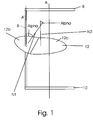
- Fig. 1 shows an embodiment of a grill device 1, wherein the frame 2 consists of an upper horizontal holding element 8 and a lower horizontal holding element 10, which are spaced from one another by a vertical frame element 6.
- the grilled food support element 12 is arranged between the upper and lower holding elements 8, 10. It consists of a first sub-area 12 b and a second sub-area 12 c, the normal vectors N1, N2 of which are at an angle alpha to one another. It can also be seen that the normal vector N1 of the first sub-area 12 b is at the same angle alpha to the normal vector N2 of the second sub-area 12 c as to the vertical longitudinal axis A, which is arranged parallel to the frame element 6.
- the first sub-area 12 b has an opening which, in the position shown, is positively connected to the frame element 6. It can also be seen that the second sub-area 12 c has a length in a horizontal direction pointing away from the frame element 6 which is at least three times as great as the length of the first sub-area 12 b in this direction. In this way, a force is exerted on the opening on the frame element 6 by the mass of the second sub-area 12 c, which enables the grilled food support element 12 to be adhesively fixed in the vertical position with respect to the frame element 6.
- One shape of the grilled food support element 12 is essentially modeled on a tongue.
- Fig. 2 shows a perspective view of the grill device 1. Reference numerals that have already been introduced are not necessarily repeated here.
- a bulge 3 is arranged on the frame element 6 on the circumferential side below the grilled food support element 2, which is larger than the opening and limits a displacement of the grill food support element 12 from below.
- the bulge 13 is designed as a circumferential rubber ring.
- the grill device 1 here has the property that an upper holding element 8 has at least one horizontal section and a rounded section, the extension of the vertical frame element 6 connecting it to the horizontal section of the upper holding element 8.
- the holding elements 8, 10 and also the frame element 6 are designed as square tubes with a square cross-section, the upper holding element 8 having a cylindrical section at its end, whose diameter is smaller than a side thickness of the square tube.
- An eyebolt 14 is arranged around this cylindrical section, which is advantageously used for the rotatable fastening of the grill device 1.
- the eyebolt 14 is held in place by a spring clip 15.
- Fig. 3 shows in more detail the construction of eyebolt 14 and spring clip 15 on the cylindrical portion. While the eyebolt 14 is held by a thickening on the side of the holding element 8 facing the frame element 6, the one on the other side is held by the said clamping spring 15. It consists of a straight rod, at the end of which a 180 ° rounding is arranged, at the end of which in turn a W-shaped section is arranged, the prongs of which contact the first rod-shaped section resiliently. If there is a through bore in the radial direction on the cylindrical section, the rod-shaped section of the clamping spring can be inserted into the through bore so that the central curvature of the "W" engages around the radial section in a clamping manner. In this way, the eyebolt 14 is held behind the clamping spring 15.
- a grill device 1 is shown, the frame 2 being formed from a frame element.
- the frame element is fixed on a holding element 8.
- a first grilled food support element 12 which is arranged on the frame element 6, is arranged on the underside.
- the frame 2 is thus designed as a "U”.
- Further grilled food support elements 14, 16, 18 are arranged within the frame 2.
- the grilling device 1 can also have more than the four grilling support elements 12, 14, 16, 18 shown here.
- the four grilled food support elements 12, 14, 16, 18 are shown here in the side view. It has proven to be advantageous to make the grillage support elements 12, 14, 16, 18 round.
- the design of the grilled food support elements 12, 14, 16, 18 is not limited to round, but can also be, for example, angular, ellipsoidal or also polygonal.
- a grillage carrier tray 12a, 14a, 16a, 18a is arranged on each of the grilled food support elements 12, 14, 16, 18.
- the grilled food support shells 12a, 14a, 16a, 18a have an upwardly widening cross-section and serve to receive grilled food during the grilling process.
- the respective grill food carrier tray 12a, 14a, 16a, 18a is on the grill food carrier element 12, 14, 16, 18 set up.
- the latter can have an at least partially circumferential, vertically upwardly extending elevation, which is designed as an edge.
- This elevation prevents the respective grilled food tray 12a, 14a, 16a, 18a from sliding down during the grilling process.
- other mounting options for the grilled food support trays 12a, 14a, 16a, 18a are also conceivable, which are suitable for the releasable fixation of the grill food support trays 12a, 14a, 16a, 18a.
- the grilling trays 12a, 14a, 16a, 18a can be individually removed during the grilling process.
- the height H between two grilled food support elements 12, 14, 16, 18 can be designed variably, the height H preferably having a distance in the range of 10-30 cm, preferably 18-28 cm.
- the holding element 8 preferably has a recess 19 (not shown), which is preferably designed as a circumferential groove. Furthermore, this recess 19 is preferably arranged centrally on the holding element 8. Via this recess 19, the grilling device 1 is releasably attached to the receiving device (not shown) with a holding means 21, which is preferably designed as a hook-like element.
- the grilled food support elements 12, 14, 16, 18 are fixedly arranged on the frame element 6 and the grilled food support trays 12a, 14a, 16a, 18a are removable.
- the grilling device 1 is rotated about its vertical longitudinal axis A at a predeterminable speed. This enables the food to be grilled evenly from all sides.
- Fig. 5 shows a further schematic cross section of a grill device 1 with a U-shaped frame 2.
- the frame 2 comprises a frame element 4, which two holding elements 8, 10 spaced from one another.
- the illustrated further embodiment of a grilling device 1 comprises two grilling support elements 2, 14, which, however, are to be understood here only for the purpose of illustration.
- the grill device 1 shown here can comprise more than the two grill items support elements 12, 14 shown.
- the grill food support elements 12, 14 each have a fixing section 82 by means of which the grill food support elements 12, 14 are detachably arranged on the frame element 4.
- the height H between the grillage support elements 12, 14 can be varied as desired and always changed depending on the grillage to be grilled.
- the height H is preferably in the range of 10-30 cm, preferably in the range of 18-28 cm.
- the holding element 8 at the upper vertical end of the grill device 1 has a coupling element 84, by means of which the grill device 1 can be detachably connected to at least one drive device (not shown).
- the further holding element 10 has at least one projection 86, which is mostly preferably designed as a guide pin and / or as an abutment 60.
- the design is not limited to this. If, for example, the drive device is provided in the vicinity of the lower vertical free end of the grill device, the arrangement of coupling element 84 and projection 86 or abutment 60 is reversed.
- the grilled food support elements 12, 14 in this exemplary embodiment are designed to be larger in their longitudinal direction, so that they protrude beyond the two holding elements 8, 10. This is advantageous because the grilled food support shells (not shown) to be received can thus be arranged in a stable manner on the grill food support elements 12, 14.
- the rotation of the here in Fig. 5 The grill device 1 shown takes place around the axis of rotation A, which extends in the longitudinal direction of the grill device 1 centrally through the coupling element and projection or abutment.
- FIG. 6 Another possible type of drive for the grilling device 1 is shown.
- the frame 2 here comprises a frame element 6 which spans a U-shaped frame via an upper and lower holding element 8, 10.
- a drive device 62 is shown which is releasably connected to the grill device 1 via a coupling element 84.
- the coupling element 84 is preferably designed as a quick coupling, mostly preferably as a slip coupling.
- the grilling device 1 there is at least one projection 86 and / or an abutment 60 which can be inserted into an opening 88 of the grill device that is designed to be complementary thereto.
- the grilling device 1 rotates about the axis of rotation A.
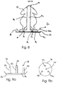
- Fig. 8 a schematic cross section of part of a grill device 1 is shown.
- the grill support element 12 has at least partially an elevation 23 on the circumference, which serves as a limiting means and protects the grill product carrier tray 12a arranged on the grill product support element 12 from slipping or sliding down during the grilling process.
- the base area of the grilled food tray 12a has a smaller diameter than the upwardly directed opening, so that a conically upwardly widening jacket area 28 is required, which ends with an edge area 24 arranged on the circumference.
- the grilled food carrier tray 12a preferably has two positioning means 30 and 32, which are designed as projections extending vertically upward. In this embodiment, the projections are shown with an angular cross-section.
- the support element 34 that can be arranged within the grilled food tray 12a comprises a base plate 36 which has recesses 38 and 40 designed to complement the positioning means 30 and 32, so that after the bottom plate 36 has been inserted, it is arranged essentially without displacement in the grilled food tray 12a.
- the support element 34 comprises a shaft-like extension 42, which extends vertically upwards, and whose free end 44 is designed as a rounded hemisphere in this example.
- the grilled food 43 is arranged schematically. It is conceivable that within this shaft-like element 42, which here has a cylindrically arranged jacket 46, at least one heating element is arranged (not shown). This heating element can for example be arranged in a spiral shape.
- the shaft-like extension 42 preferably has a vertical length L in the range from 7-25 cm, preferably from 10-18 cm, and a width B in the range from 2-8 cm, preferably in the range from 3-6 cm.
- the grilled food support element 12 itself is designed in the shape of a shell and if a separate grill food support shell 12a is dispensed with, then the above-mentioned fixing of the support element 34 can be applied analogously to the grill food support element 12.
- FIG 9a shows a schematic side view of a further advantageous embodiment of the grill item carrier element 12 with a support element 34 which comprises a base plate 36.
- the fixing of the support element 34 is not shown again here for the sake of simplicity.
- the support element 34 further comprises three shaft-like extensions 42 extending upward, the arrangement of which in the plan view in FIG Figure 8b is made clear.
- the triangular arrangement of the shaft-like extensions 42 on the base plate 36 is preferably carried out in such a way that the grilled food (not shown) can be arranged and fixed in the spanned intermediate area 45.
- the shaft-like extensions 42 are preferably cylindrical and each have a beveled surface area 90 at their upwardly directed free end.
- the bevel is advantageously made at an angle between 20-80 °, mostly preferably between 30-50 °. This bevel is particularly advantageous because it allows the grilled food that can be arranged in the intermediate region 45 to be easily positioned and fixed during the grilling process.
- the grilled food support element 12 described here proves to be particularly advantageous for grilling knuckles or baked ham.
- the upwardly extending, shaft-like extensions 42 hold the grilled food in such a way that improved heat circulation takes place, particularly in the bottom area of the grilled food tray, so that the grilled food is also cooked and grilled from below.
- the design is not limited to just three shaft-like extensions, but can be expanded as required, depending on the size of the food to be grilled.
- a carrier element which in the simplest case is designed as a carrier ring (not shown).
- the food to be grilled is positioned on the carrier ring and is spaced apart from the dish of the grilled food by the shaft-like extensions 42 extending upward, so that heat circulation continues to be promoted.
- the carrier element is preferably made of metal and / or plastic and / or composite material and / or a mixture thereof. In addition to metal, heat-resistant plastic has also proven to be particularly advantageous.
- FIG. 7 a schematic structure of a grill device 47 is shown, in which only one grill device 1 is provided.
- the grilling device 1 itself comprises, as in FIG Fig. 1 shown, a frame 2 and a frame element 6.
- the grill food support elements arranged in the frame 2 are not shown here for the sake of simplicity.
- the grilling device 1 preferably has a holding means 21 on its holding element 8, preferably on both holding elements 8, 10, by means of which the grilling device 1 can be releasably arranged on the receiving device 50.
- the drive device (not shown here) causes the grill device 1 to rotate about its vertical longitudinal axis A.
- the housing of the grill device 47 comprises a U-shaped heating element 52, which consists of a total of three flat heating sections 54, 56, 58. It is preferably conceivable that the grilling device 1 also has an abutment 60 so that a uniform rotation is made possible. Of course, this is only to be seen as an example. In addition, grills are also conceivable which can accommodate a large number of grilling devices 1 in order to finish correspondingly large quantities of grilled food at the same time.
- FIG. 10 Another grill device 47 is shown, which comprises a grill housing 52 and a total of four of the grill devices 1 arranged therein.
- the four grilling devices 1 are arranged here in a row next to one another. For the sake of clarity, grilled food trays and grilled food are not shown here. It goes without saying, however, that for the grill device 47 described here, the grill food support trays described above or grill food support elements designed in the manner of a shell are to be provided.
- the grill housing 52 preferably comprises a plurality of horizontally arranged heating elements 54, 56, 58, 59.
- the grill devices 1 are suspended by means of holding means 21 (not shown), which are preferably designed as a hook-like element.
- the holding means 21 serves as a link between the grill device 1 and the receiving device 50.
- the receiving device 50 is each connected to a drive device 62, 64, 66, 68.
- the drive device is preferably understood to be a motor drive, by means of which the respective grilling device 1 can be rotated about its respective longitudinal axis A. It is conceivable that each grill device 1 has a separate drive device 62, 64, 66, 68 so that the four grill devices 1 shown here can be rotated at different speeds that are independent of one another. It is also preferred that only one drive device 62 is provided for all grilling devices 1, so that all grilling devices 1 are subjected to the same rotational speed.
- the individual grilling devices 1 are advantageously driven via a toothed belt (not shown) which is driven by one drive device 62.
- the grill housing 52 also advantageously comprises at least one, preferably two, movably arranged side surfaces 70, 72, which are mostly preferably arranged pivotably on the grill housing 52.
- the side surfaces 70, 72 preferably have two grip elements 74, 76 by means of which the two side surfaces 70, 72 can be pivoted.
- the in Fig. 6 The grill housing 52 shown, the two side surfaces 70, 72 are shown pivoted outward in the open state. In this state, the grilling devices 1 are loaded. If all grilling devices 1 are equipped with grilled food (not shown), the two side surfaces 70, 72 are pivoted inward and the grilling space 78 is closed.
- the grill space 78 is to be understood as the space in which the grill devices 1 are arranged.
- the pivotable arrangement of the two side surfaces 70, 72 proves to be advantageous since the food to be grilled is grilled in an almost closed grilling space 78 and the grilling time is thus significantly shortened in contrast to open grilling devices from the prior art.
- the side surfaces 70, 72 are preferably made of heat-resistant, transparent material so that the food to be grilled is visible and can be checked at any time without the grill housing 52 having to be opened.
- the side surfaces 70, 72 are preferably designed like doors.
- FIG 11 shows a possible embodiment of a coupling element 84.
- the coupling element 84 here consists of a cylinder 110 and a piston 111, the coupling element 84 being non-positive between the cylinder 110 and the piston 111.
- the piston 111 is connected to a motor 62 and the cylinder 110 is preferably connected to the frame 2 via a thermally insulating element.
- the frame 2 is shown only schematically without its individual parts. It is also conceivable to swap the positions of piston 111 and cylinder 110 Figure 11 a roller bearing 115 is provided, preferably in an upper section of the frame 2.
- a guide rod with a pressing element 113 in particular a spring, is provided in the piston, which exerts a pressing force radially outward.
- the grinding surfaces 112 are provided on this spring, the two grinding surfaces 112 preferably made of an abrasion-resistant and / or elastic material, such as Example a hard rubber are provided. Furthermore, a support element 114 is provided, which rests on the inner ring of the roller bearing 115, so that the frame 2 is supported in a suspended manner on the roller bearing 115.
- the support element 114 can be designed as a thermally decoupling element, for example as a ceramic disk. It is also possible for a projection 86 to be provided on the underside of the frame 2, which is guided in a part of the housing 00. This guide can prevent the frame 2 from swinging.
- Figure 12 shows possible design variants of a non-rotationally symmetrical cross-section of the frame element 6.
Landscapes
- Engineering & Computer Science (AREA)
- Food Science & Technology (AREA)
- Baking, Grill, Roasting (AREA)
Description
- Die Erfindung betrifft eine Grillvorrichtung zum Grillen von Grillgut.
- Im vorbekannten Stand der Technik sind Grillvorrichtungen zum Grillen von Grillgut bekannt, welche zur Sicherung einzelner Elemente, insbesondere der Grillgutträger zusätzliche Befestigungselemente, wie zum Beispiel Schrauben benötigen, um eine sichere Verbindung zwischen dem Grillgutträger und dem dazugehörigen Gestell sicherzustellen
WO 03/022115 A2 - Nachteilig hierbei ist, dass das Entfernen sowie das Anbringen der Grillgutträger durch die zusätzlichen Befestigungsmittel aufwendig ist. Weiterhin kann sich durch die Hitze das Material der Befestigungsmittel derart verformen, dass ein Lösen nicht mehr möglich oder zumindest erschwert ist.
- Weitere relevante Stand der Technik Dokumente sind beispielsweise
US 2 831 421 A undDE 10 2013 020112 A1 . - Es ist Aufgabe der vorliegenden Erfindung eine Grillvorrichtung bereitzustellen, welche eine erleichterte Entnahme oder ein erleichtertes und sicheres Anbringen und Justieren der Grillgutträger ermöglicht. Insbesondere soll die Sicherheit für den Bediener beim Betrieb der Vorrichtung erhöht werden. Zudem soll ein Grillgutteller bereitgestellt werden, welcher für verschiedenartiges Grillgut ausgestaltet ist.
- Diese Aufgaben werden durch die Merkmale des unabhängigen Anspruchs 1 gelöst.
- Die Erfindung betrifft eine Grillvorrichtung zum Grillen von Grillgut umfassend wenigstens ein Gestell, mit wenigstens einem Gestellelement sowie mit wenigstens einem Halteelement, zum Beispiel oberen Halteelement und/oder einem unteren Halteelement, welches an einem oberen Ende des Gestellelementes angeordnet ist wobei die Grillvorrichtung um eine vertikale Längsachse rotierbar ausgebildet ist. Ferner kann sie mit wenigstens einem Grillgutträgerelement ausgestattet bzw. zu seiner Halterung geeignet sein. Die Grillvorrichtung kann insbesondere, im Falle eines oberen Halteelements, hängend und/oder, im Falle eines unteren Halteelements, stehend entlang der vertikalen Drehachse gelagert sein. Ein Kerngedanke der Erfindung ist, dass das Gestellelement bezüglich der vertikalen Drehachse exzentrisch angeordnet ist, damit das Grillgut zentrisch angeordnet sein kann. Insbesondere kann das Grillgut so liegend angeordnet werden, ohne dass man es gesondert arretieren, beispielsweise aufspießen, müsste. Die zentrische Anordnung des Grillguts hat den Vorteil, dass es so bei Rotation um die vertikale Drehachse einen im Wesentlichen (in Abhängigkeit beispielsweise von der Form des Grillguts) konstanten Abstand haben kann, damit es umfänglich möglichst gleichmäßig gegart werden kann.
- Das wenigstens eine Grillgutträgerelement weist einen ersten Teilbereich auf, welcher mit einer Öffnung ausgestattet ist, durch welche das Gestellelement führbar ist. Das Gestellelement weist dabei einen nicht-rotationssymmetrischen Querschnitt auf, derart, dass das Grillgutträgerelement und das Gestellelement bezüglich einer Ebene, in der die vertikale Längsachse nicht liegt, also beispielsweise einer Normalenebene der vertikalen Längsachse formschlüssig zusammenwirken. So lässt sich das Grillgutträgerelement nur in Richtung der vertikalen Längsachse verschieben, aber nicht in einer dazu orthogonalen Richtung verdrehen. Ein nicht-rotationssymmetrischer Querschnitt ist bezüglich des Formschlusses von Vorteil, da bei rotationssymmetrischen Querschnitten die Gefahr eines ungewollten Verschiebens oder Abrutschens des Grillgutträgerelements besteht. Unter Längsachse ist hierbei diejenige Achse zu verstehen, in welcher die Grillvorrichtung ihre längste geometrische Ausdehnung aufweist. Bevorzugt ist die Längsachse gleichzeitig die zentrale Mittelachse der Grillvorrichtung. Insbesondere kann die vertikale Längsachse in Richtung der Schwerkraft ausgerichtet sein. Durch die Rotation der Grillvorrichtung um eine vertikale Längsachse wird ein gleichmäßiges Grillen des Grillguts ermöglicht. Es handelt sich folglich um eine vertikale Grillvorrichtung.
- Weitere vorteilhafte Ausführungsformen ergeben sich aus den Unteransprüchen.
- Weiterhin weist das Grillgutträgerelement bezüglich der Öffnung eine asymmetrische Gewichtsverteilung auf, so dass das Grillgutträgerelement und das Gestellelement bezüglich der vertikalen Längsachse kraftschlüssig, insbesondere durch eine Klemmverbindung, zusammenwirken. Durch diese asymmetrische Gewichtsverteilung wird das Grillgutträgerelement beispielsweise aufgrund der Schwerkraft in eine Position gebracht, in welcher sich das Grillgutträgerelement mit dem Gestellelement verklemmt, wodurch ein Kraftschluss erreicht wird. Dadurch ist es möglich, auf einfache und schnell einstellbare Weise eine sichere Verbindung auch ohne zusätzliche Befestigungsmittel zu erhalten, die man am heißen und meist von Fett und Essensresten bedeckten Gestellelement anbringen müsste. In dieser Verbindung entstehen zumindest zwei Kontaktpunkte zwischen der Öffnung und dem Gestellelement. Eine kraftschlüssige Verbindung entlang der vertikalen Längsachse aber eine vorzugsweise formschlüssige Verbindung in dazu orthogonalen Richtungen zwischen dem Grillgutträgerelement und dem Gestellelement ist vorteilhaft, da das Grillgutträgerelement zusammen mit dem Gestellelement verschwenkt werden soll. Hierbei soll jedoch sichergestellt sein, dass das Grillgutträgerelement während der Drehung in der vorher festgelegten Position verbleibt. Hierbei muss die kraftschlüssige Verbindung auf die durch die kontinuierliche Drehung dauerhaft auftretenden Kräfte ausgelegt sein, so dass ein Abrutschen verhindert wird, selbst wenn die Kontaktflächen mit einem Stoff mit Schmierwirkung, wie beispielsweise Fett, benetzt sind.
- Besonders bevorzugt weist die Öffnung des ersten Teilbereichs des Grillgutträgers in einer horizontalen Richtung eine Länge auf, welche größer ausgestaltet ist, als die Dicke des Gestellelements. Durch diese Ausgestaltung wird sichergestellt, dass der Grillgutträger leichtgängig über das Gestellelement geführt werden kann, ohne vorzeitig zu Verkanten bzw. zu Verklemmen.
- In einer weiteren bevorzugten Ausführungsform weist der erste Teilbereich des Grillgutträgers in einer Position der formschlüssigen Verbindung eine Neigung bezüglich der Normalenebene auf. Der erste Teilbereich ist demnach nicht horizontal ausgerichtet, sondern ist zum Herstellen einer Klemmverbindung geneigt. Durch ein solches Verklemmen wird eine sichere Verbindung erreicht.
- Bevorzugt weist das Grillgutträgerelement einen zweiten Teilbereich auf, welcher zur Aufnähme des Grillguts selbst oder wenigstens zur Aufnahme eines Grillguttellers ausgestaltet ist. Hierfür kann der zweite Teilbereich zum Beispiel direkt als Grillgutteller ausgestaltet sein, welcher direkt das Grillgut aufnehmen kann. Vorzugsweise wird der zweite Teilbereich beispielsweise durch eine Aufnahmevorrichtung wie zwei Streben gebildet, welche einen separaten Grillgutteller aufnehmen können. Ein Vorteil der Ausgestaltung des zweiten Teilbereichs als Aufnahmeeinrichtung ist, dass der Grillgutteller einfacher und schneller austauschbar ist. Bei einer möglichen Beschädigung des Grillguttellers muss lediglich der Teller selbst und nicht das gesamte Grillgutträgerelement ausgewechselt werden. Weiterhin ist das Grillgutträgerelement hinsichtlich unterschiedlicher Arten des Grillguts variabler, da bei Änderung des Grillguts lediglich ein anderer Grillgutteller verwendet werden muss.
- In einer weiteren bevorzugten Ausführung weist der zweite Teilbereich in einer horizontalen von dem Gestellelement weg weisenden Richtung eine Länge auf, die wenigstens dreimal so groß ist wie die Länge des ersten Teilbereichs in dieser Richtung. Durch die unterschiedlichen Größenverhältnisse wird die asymmetrische Gewichtsverteilung begünstigt. Weiterhin ermöglicht eine größere Länge des zweiten Teilbereiches ein Materialgewicht, das ausreichend ist, um eine ausreichende Haftreibung eines Innenbereiches der Öffnung an dem Gestellelement bereitzustellen, damit das Grillgutträgerelement in seiner Position an dem Gestellelement fixiert bleibt. Eine größere Länge des zweiten Teilbereiches ermöglicht auch einen zweiten Teilbereich, der groß genug ist, um ein entsprechend großes Grillgut aufzunehmen. Vorteilhaft ist für die Form des zweiten Teilbereiches eine Form, die in etwa einem Teller nachempfunden ist. Die Form des zweiten Teilbereiches ist jedoch nicht darauf beschränkt. Es ist denkbar, dass der erste und zweite Teilbereich zusammen in etwa die Form einer Zunge aufweisen, die sich von dem ersten Teilbereich ausgehend verbreitert und dann wieder in einer runden Form zusammenläuft. Auf diese Weise kann eine gute Halterung an dem Gestellelement mit einer für ein Grillgut vorteilhaften Oberfläche gleichzeitig gewährleistet sein. Weiterhin vorteilhaft ist auf diese Weise eine Entnahme des Grillgutes oder eine Bestückung mit Grillgut sehr einfach, da ein Aufnahmeraum des Grillgutes lediglich von einem Gestellelement verdeckt wird und so in einem 360° Grad Bereich das Grillgut von allen Seiten zugänglich ist.
- Darüber hinaus ist es vorteilhaft, dass das wenigstens eine Grillgutträgerelement bevorzugt mit einem im Wesentlichen L-förmigen Abschnitt ausgebildet ist. Erfindungsgemäß sind unter "L-förmig" alle Abschnitte zu verstehen, die aus zwei Unterabschnitten, die unter einem Winkel zueinander stehen mit einem eckigen oder gerundeten Verbindungsstück.
- Bevorzugt erstreckt sich der zweite Teilbereich in einer Position einer formschlüssigen Verbindung zwischen dem Grillgutträgerelement und dem Gestellelement im Wesentlichen in einer horizontalen Richtung. Eine solche horizontale Ausrichtung ist notwendig, damit ein Abrutschen des Grillguts, welches sich auf dem zweiten Teilbereich befindet, verhindert wird.
- Besonders bevorzugt weist das Gestellelement ein weiteres Halteelement an der Unterseite des Gestellelements und/oder eine Führung in der Normalenebene auf. Eine Führung ist in diesem Bereich besonders vorteilhaft, um ein Schwingen des Gestells bei Rotation zu vermeiden.
- In einer weiteren vorteilhaften Ausgestaltung ist das Gestellelement durch Ziehen hergestellt und weist einen gekrümmten Bereich auf. Dabei verjüngt sich das Profil in dem gekrümmten Bereich. Die Verjüngung tritt besonders bevorzugt an der Außenseite des Profils auf, also in dem Bereich der Krümmung, welcher den größten Krümmungsradius aufweist.
- In einer bevorzugten Ausführungsform der Grillvorrichtung ist oberhalb des oberen Halteelements in Richtung der vertikalen Längsachse ein Wälzlager angeordnet. Dabei erstreckt sich ein Teil des oberen Halteelements in Richtung der vertikalen Längsachse nach oben und ist durch das Wälzlager geführt.
- Bevorzugt weist der Teil des oberen Haltelements, welcher durch das Wälzlager geführt ist, zumindest eine Auflagefläche zur Auflage des Halteelements auf dem Wälzlager auf. Diese Auflagefläche kann auf dem inneren Ring des Wälzlagers aufliegen oder daran befestigt sein. Dies bietet den Vorteil, dass das Gewicht des Gestells von dem Lager getragen wird, was zu einer reduzierten Belastung des Antriebs führt.
- Vorzugsweise umfasst die Grillvorrichtung eine Kupplung mit einem Kolben und einem Zylinder zur Übertragung einer rotatorischen Bewegung auf ein Gestell einer Grillvorrichtung. Erfindungsgemäß ist die Kupplung zwischen Kolben und Zylinder eine kraftschlüssige Kupplung. Besonders bevorzugt handelt es sich bei der kraftschlüssigen Kupplung um eine Rutschkupplung. Eine solche Kupplung bietet einen erheblichen Sicherheitsvorteil, da diese bei Überschreiten einer Maximalkraft selbsttätig auskoppelt. In dem Fall, dass der Bediener zum Beispiel mit seiner Hand oder seinem Arm zwischen zwei rotierende Grillgutträger gerät, koppelt die Kupplung aus und stoppt so die Rotation der Grillgutträger.
- In einer bevorzugten Ausführungsform der Kupplung weisen der Kolben und der Zylinder einen in Axialrichtung rotationssymmetrischen Querschnitt auf.
- Außerdem weist die Kupplung eine Anzahl an Schleifflächen auf, welche zur Herstellung eines definierten Kraftschlusses zwischen Kolben und Zylinder geeignet sind. Weiterhin ist die Anzahl an Schleifflächen in dem Kolben oder dem Zylinder radialbeweglich angeordnet, wobei die Schleifflächen einen Kraftschluss durch eine Andrückkraft in radialer Richtung erzeugen.
- In einer weiteren bevorzugten Ausführungsform ist die Anzahl an Schleifflächen mit einem Andrückelement verbunden, welches die Schleifflächen mit einer vordefinierten Kraft beaufschlagt. Dabei sind bevorzugt bei Überschreiten eines definierten Schwellwerts der Andrücckraft der Kolben und der Zylinder gegeneinander beweglich. Bei dem Andrückelement kann es sich beispielsweise um eine Feder handeln, deren Federkonstante derart festgelegt ist, um die notwendige Kraft zu erzeugen.
- Bevorzugt ist eine Unterseite des Kolbens als Schleiffläche ausgebildet, welche in axialer Richtung beweglich ist und durch welche ein Kraftschluss in axialer Richtung erzeugbar ist.
- Weiterhin ist bevorzugt eine Arretiervorrichtung vorgesehen, durch welche die Schleifflächen in einer Position arretierbar sind, in welcher kein Kraftschluss hergestellt ist.
- In einer weiteren bevorzugten Ausführungsform ist die Kupplung durch ein Element zur thermischen Isolierung von einer Grillvorrichtung thermisch entkoppelt. Dieses Element zur thermischen Isolierung kann in einer bevorzugten Ausführungsform gleichzeitig als Auflageelement ausgebildet sein.
- Mit der Grillvorrichtung kann ein Grillgutteller verwendet werden. Der Grillgutteller ist mit einer Führung an der Unterseite versehen, welche an die Form des zweiten Teilbereichs des Grillgutträgers angepasst ist, wodurch der Grillgutteller an dem zweiten Teilbereich des Grillgutträgerelements anbringbar ist. Bei der Führung kann es sich um eine Anzahl an länglichen Vertiefungen handeln, falls der zweite Teilbereich durch Streben ausgebildet ist. Allerdings sind auch anders geformte Aussparungen denkbar, welche an die jeweilige Ausgestaltung des zweiten Teilbereichs angepasst sind.
- In einer bevorzugten Ausführungsform weist der Grillgutteller wenigstens eine Erhebung zum Halten eines Grillguts mit einem Hohlraum auf. Die Erhebungen können unter anderem Zapfen sein, welche in das Grillgut eingeführt werden. Diese Zapfen können auch beheizt sein, um das Grillgut auch von innen zu erwärmen, was zu einem gleichmäßigeren Garen führen kann.
- In einer bevorzugten Ausführungsform sind Gestell, Gestellelement sowie Halteelement aus Metall, beispielsweise aus Edelstahl oder Aluminium, ausgebildet. Darüber hinaus ist denkbar, dass die Oberflächen der Gestellelemente sowie der Halteelemente physikalisch und/oder chemisch modifiziert ausgebildet sind und beispielsweise oberflächenbehandelt oder oberflächenbeschichtet eingesetzt werden. Dies ist insbesondere bei dem Kontakt mit Lebensmitteln von Vorteil, da durch die Oberflächenbehandlung das Bakterienwachstum sowie das Pilzwachstum gehindert wird, sodass das Gestell antimikrobiell und/oder desinfizierbar ist. Ferner ist denkbar, dass Gestell, Gestellelement sowie Halteelemente als Drahtbiegekonstruktion ausgebildet sind.
- Darüber hinaus umfasst die erfindungsgemäße Grillvorrichtung wenigstens ein Grillgutträgerelement zur Aufnahme des Grillguts. Dies ist vorteilhaft, da somit das Grillgut in der Grillgutvorrichtung anordenbar ist und während eines Grillvorgangs gegart werden kann.
- Bei einer weiteren vorteilhaften Ausführungsform sind wenigstens ein, bevorzugt mehrere, Grillgutträgerelemente vertikal voneinander beabstandet an dem Halterahmen angeordnet. Dies ist vorteilhaft, da insbesondere jedes Grillgutträgerelement bevorzugt ein Grillgut, beispielsweise ein Grillhähnchen, aufnimmt. Sind mehrere derartige Grillgutträgerelemente an dem Halterahmen angeordnet, können mehrere Grillhähnchen gleichzeitig gegrillt werden.
- Bevorzugt können die Grillgutträgerelemente derart voneinander beabstandet angeordnet sein, dass die jeweiligen Grillgüter zueinander kontaktfrei angeordnet sind. Dies ist vorteilhaft, da somit das Grillgut von allen Seiten gegrillt werden kann und rohe Halsbereiche, wie sie durch das enge bestücken der Grillspieße aus dem Stand der Technik bekannt sind, vermieden werden. Dies ist zusätzlich vorteilhaft, da durch die Beabstandung des Grillguts voneinander eine schnelle Entnahme von jedem einzelnen Grillgut sowie eine schnelle Neubestückung mit rohem Grillgut ermöglicht wird. Je nach Grillgutgröße kann das Grillgut, insbesondere ein Grillhähnchen, einzeln der Grillvorrichtung entnommen werden, ohne dass das restliche Grillgut hierdurch beeinträchtigt wird. Ist ein kleineres Grillhähnchen gar, so kann es direkt entnommen werden, um eine saftige Fleischqualität zu gewährleisten. Das restliche Grillgut, also größere, schwerere Grillhähnchen, welche noch nicht gar sind, verbleiben derweil in der Grillvorrichtung und werden weiter gegrillt. Dies bringt sowohl einen Zeitvorteil als auch einen reduzierten Arbeitsaufwand mit sich.
- Vorteilhafterweise weist das Gestellelement eine Vielzahl an vertikal voneinander beabstandeten Vertiefungen auf, welche im einfachsten Fall bevorzugt als Führungsnuten ausgebildet sind. In diese Vertiefungen ist das wenigstens eine Grillgutträgerelement zumindest teilweise einführbar und lösbar fixiert. Je nach Ausbildung können diese Vertiefungen gleiche oder auch voneinander verschiedene Abstände zueinander aufweisen. Diese variable Anordnung des wenigstens einen Grillgutträgerelementes ist insbesondere vorteilhaft, wenn unterschiedlich großes Grillgut gegrillt werden soll. Vorteilhaft sind mehrere Grillgutträgerelemente, bevorzugt zwei bis zehn Grillgutträgerelemente an dem Halterahmen angeordnet. Weiterhin bevorzugt sind die Grillgutträgerelemente im Bereich von 10 - 30 cm vertikal voneinander beabstandet angeordnet.
- Vorteilhafterweise können die Vertiefungen eine weitere Stützfunktion zu der Haftreibung bereitstellen. Bevorzugt sind sie als Einkerbungen auf einer Seite des Gestellelementes, die zu den zweiten Teilbereichen gerichtet ist und auf einer davon abgewandten Seite des Gestellelements angeordnet. Dies bewirkt eine besonders einfache und zugleich stabile Stützfunktion.
- In einer weiteren vorteilhaften Ausführungsform ist das Gestellelement als Vierkantrohr mit bevorzugt quadratischem Querschnitt und besonders bevorzugt abgerundeten Ecken ausgebildet. Dies ist vorteilhaft, da dies eine einfache Ausführungsform ist, die gleichzeitig der Funktionalität besonders dienlich ist. Auf diese Weise ist es möglich, die Öffnung an dem ersten Teilbereich rechteckförmig mit einer Seite, die einer Länge des Vierkantrohres entspricht sowie einer längeren Seite ausgebildet ist. In einer geneigten Position passt sich dann auch die längere Länge dem quadratischen Vierkantrohr an. Auf diese Weise kann die Bedingung, dass eine geneigte Position des ersten Teilbereiches zu der vertikalen Längsachse existiert, in der die Öffnung formschlüssig zu dem Gestellelement und der zweite Teilbereich senkrecht zu der vertikalen Längsachse ist, besonders einfach realisiert werden. Vorteilhaft ist es denkbar, dass Vertiefungen als Einkerbungen in unterschiedlicher Höhe ausgebildet sind. Dabei ist vorteilhaft eine Einkerbung dem zweiten Teilbereich zugewandt an dem Gestellelement und eine von dem zweiten Teilbereich abgewandt an dem Gestellelement. Der Höhenunterschied wird vorteilhaft derart angepasst, dass eine schräge Verbindung der beiden Einkerbungen exakt einer zweiten Rechtecklänge der Öffnung entspricht. Auf diese Weise können gestufte Höheneinstellungen des Grillgutträgerelements gewährleistet werden. Selbstverständlich ist eine Form des Gestellelements nicht auf die Form eines Vierkantrohres beschränkt. So ist auch die Form eines runden Rohres, die Form eines rechteckigen Rohres oder die Form eines elliptischen Rohres möglich. Auch sämtliche andere vorstellbare Profilformen sind denkbar. Beispielsweise kann die Form eines Gestellelementes zu Werbezwecken auch einer Trickfigur angepasst werden. Anstelle eines Rohres kann auch eine Vollstange verwendet werden. Dies erhöht vorteilhaft eine Stabilität. Die abgerundeten Ecken sind vorteilhaft, da auf diese Weise einer Verletzungsgefahr vorgebeugt wird.
- In einer weiteren vorteilhaften Ausführungsform ist an dem Gestellelement umfangsseitig unter dem Grillgutträgerelement eine Wölbung, bevorzugt in Form eines Gummirings, angeordnet, die größer als die Öffnung ist und eine Verschiebung des Grillgutträgerelements von unten begrenzt. Vorteilhaft wird damit die Sicherheit der Grillvorrichtung erhöht. Sollte das Grillgutträgerelement bei einem vertikalen Verstellen einmal abrutschen, kann es maximal bis zu der Wölbung hinunterrutschen und wird von dieser aufgefangen. Ein Gummiring ist darüber hinaus vorteilhaft, da er zusätzlich noch abfedernd wirkt.
- In einer weiteren vorteilhaften Ausführungsform weisen die Halteelemente wenigstens einen horizontalen Abschnitt und bevorzugt weiterhin einen abgerundeten Abschnitt auf, der als Verlängerung des vertikalen Gestellelementes dieses mit dem horizontalen Abschnitt verbindet. Ein horizontaler Abschnitt erlaubt vorteilhaft eine Beabstandung des Gestellelementes von einer Rotationsaufhängung. Auf diese Weise kann eine Rotation in etwa um einen Schwerpunkt der Grillvorrichtung ermöglicht werden. Eine abgerundete Verbindung des horizontalen Abschnittes des Halteelementes mit dem vertikalen Gestellelement ist darüber hinaus materialsparend.
- In einer weiteren vorteilhaften Ausführungsform sind die Halteelemente als Vierkantrohr mit bevorzugt quadratischem Querschnitt und besonders bevorzugt abgerundeten Ecken ausgebildet und weisen an ihrem Ende einen zylinderförmigen Abschnitt auf, dessen Durchmesser bevorzugt kleiner als eine Seitendicke des Vierkantrohres ist. Auch hier ist die Form der Halteelemente nicht auf die quadratische Form beschränkt. Eine rechteckförmige Form, eine elliptische Form sowie jede andere denkbare Form ist möglich. Eine Vierkantform ist jedoch vorteilhaft, da sie besonders leicht herstellbar ist. Weiterhin gestattet ein zylinderförmiger Abschnitt an dem Ende der Halteelemente eine besonders vorteilhafte Aufhängung der Vorrichtung.
- In einer weiteren vorteilhaften Ausführungsform ist jeweils eine Augenschraube mit ihrem Auge über dem zylinderförmigen Abschnitt zur rotierbaren Befestigung des Gestells und die vertikale Längsachse angeordnet. Eine Augenschraube ist besonders einfach und gleichzeitig stabil. Sie ermöglicht eine besonders passgenaue Anordnung des Auges der Augenschraube an dem zylinderförmigen Abschnitt.
- Bei einer weiteren vorteilhaften Ausführungsform umfasst das wenigstens eine Grillgutträgerelement wenigstens eine Grillgutträgerschale zur Aufnahme von Grillflüssigkeit während des Grillvorgangs. Dies ist insbesondere von Vorteil, da die Grillgutträgerschale die Fleischsäfte und das flüssige Fett, welches während des Grillens von dem Grillgut austritt, auffängt und ein Heruntertropfen auf weiteres, darunter angeordnetes Grillgut verhindert. Somit wird eine Geschmacksbeeinträchtigung ausgeschlossen und die Hygiene verbessert. Im einfachsten Fall ist die Grillgutträgerschale lösbar auf dem Grillgutträgerelemente angeordnet. Dies ermöglicht vorteilhaft eine schnelle Entnahme des fertigen Grillguts mit der Grillgutträgerschale sowie eine schnelle Neubestückung mit rohem Grillgut. In einem vorbereitenden Schritt werden die Grillgutträgerschalen mit bevorzugt jeweils einem Grillhähnchen bestückt, und bei Bedarf wird die fertige Grillgutträgerschale auf dem korrespondierendem Grillgutträgerelement angeordnet.
- Zur lösbaren Anordnung der wenigstens einen Grillgutträgerschale auf dem wenigstens einen Grillgutträgerelement erweist es sich als vorteilhaft, wenn das Grillgutträgerelement eine zumindest teilweise umfangsseitige, sich in vertikaler Richtung erstreckende Erhebung aufweist. Diese bevorzugt als Randbereich ausgebildete Erhebung dient der Halterung der wenigstens einen Grillgutträgerschale und verhindert deren Abrutschen von dem Griiigutträgerelement während des Grillvorgangs. Neben derartigen Erhebungen sind auch weitere Halterungselemente denkbar, wie beispielsweise Führungsnuten oder anderweitige Vertiefungen, welche die wenigstens eine Grillgutträgerschale während des Grillvorgangs auf dem Grillgutträgerelement halten.
- Bevorzugt umfasst jedes vorgesehene Grillgutträgerelement eine korrespondierende Grillgutträgerschale. Die Grillgutträgerschalen sind bevorzugt aus Metall, beispielsweise Edelstahl oder Aluminium, oder auch aus hitzebeständigem Kunststoff ausgebildet.
- Ferner wäre es auch denkbar, das wenigstens ein Grillgutträgerelement netzförmig und/oder schwammartig auszubilden, so dass Fleischsäfte und flüssiges Fett von dem wenigstens einem Grillgutträgerelement aufnehmbar und speicherbar sind. Hierzu kann das wenigstens eine Grillgutträgerelement beispielsweise mehrlagig ausgebildet sein und zwei netzartige Deckschichten, beispielsweise aus Metall, sowie eine dazwischen angeordnete Saugschicht, bevorzugt aus natürlichen und/oder künstlichen Materialien wie beispielsweise Vlies, Fasern oder aufgeschäumten Kunststoffen, umfassen.
- Vorteilhaft weist die wenigstens eine Grillgutträgerschale einen sich nach oben erweiternden, umfangsseitig erstreckenden Randbereich auf. Die wenigstens eine Grillgutträgerschale weist somit eine sich nach oben erweiternde Öffnung auf, welche bevorzugt einen Durchmesser von 10 - 30 cm, bevorzugt von 12 - 22 cm, aufweist. Die im Vergleich zur Öffnung kleinere Grundfläche der Grillgutträgerschale weist bevorzugt einen Durchmesser im Bereich von 8 - 25 cm, mehr bevorzugt von 10 - 20 cm, auf. Je nach Art des Grillguts kann der zwischen Randbereich und Grundfläche angeordnete Mantelbereich unterschiedlich hoch ausgebildet sein. Selbstverständlich ist auch denkbar, dass Öffnung und Grundfläche den gleichen Durchmesser aufweisen oder auch, dass die Öffnung kleiner als die Grundfläche ausgebildet ist. Dies ist vorteilhaft, da ein sich konisch nach oben verjüngender Mantelbereich als Spritzschutz wirkt und Fleischsäfte und Fette spritzsicher aufgefangen werden. Wird auf eine separate Grillgutträgerschale verzichtet, so ist das wenigstens eine Grillgutträgerelement selbst als Grillgutträgerschale ausgebildet und weist eine sich nach oben erweiternde Öffnung auf, welche bevorzugt einen Durchmesser von 10 - 30 cm, bevorzugt von 12 - 22 cm, aufweist. Die im Vergleich zur Öffnung kleinere Grundfläche des schalenartigen Grillgutträgerelements weist bevorzugt einen Durchmesser im Bereich von 8 - 25 cm, mehr bevorzugt von 10 - 20 cm, auf. Je nach Art des Grillguts kann der zwischen Randbereich und Grundfläche angeordnete Mantelbereich unterschiedlich hoch ausgebildet sein. Selbstverständlich ist auch denkbar, dass Öffnung und Grundfläche den gleichen Durchmesser aufweisen oder auch, dass die Öffnung kleiner als die Grundfläche ausgebildet ist.
- Vorteilhaft umfasst das wenigstens eine Grillgutträgerelement wenigstens ein Positionierungsmittel zur lösbaren Anordnung wenigstens eines Stützelements innerhalb des Grillgutträgerelements. Bevorzugt weist die wenigstens eine Grillgutträgerschale ein derartiges Positionierungsmittel zur lösbaren Anordnung wenigstens eines Stützelements innerhalb der Grillgutträgerschale auf. Dies ist vorteilhaft, da die Grillgutträgerschale für ein gleichmäßiges Grillen und Durchgaren des Grillgutes nicht ausreicht, da immer eine Seite des Grillgutes aufliegt und somit schlecht bzw. gar nicht mitgegrillt wird. Aus diesem Grund ist es besonders vorteilhaft, wenigstens ein Stützelement vorzusehen, auf welchem das Grillgut angeordnet ist. Um das Stützelement an dem Grillgutträgerelement, bevorzugt an der Grillgutträgerschale, lösbar zu fixieren, ist vorteilhaft, wenigstens ein Positionierungsmittel vorgesehen, mittels welchem das Stützelement in der bestmöglichen Grillposition für das Grillgut lösbar angeordnet werden kann.
- Vorteilhaft umfasst das Stützelement wenigstens eine Bodenplatte sowie eine daran angeordnete schaftartige Verlängerung. Dies ist vorteilhaft, da bevorzugt die Bodenplatte als Kontaktfläche zu dem entsprechenden Grillgutträgerelement, bevorzugt zu der Grillgutträgerschale, ausgebildet ist und somit zur Stabilisierung des gesamten Stützelementes dient. Die an der Bodenplatte angeordnete schaftartige Verlängerung weist eine sich in vertikaler Richtung nach oben erstreckende Verlängerung auf, auf welche das Grillgut bevorzugt von oben nach unten aufsteckbar ist. Folglich ist das Grillgut, insbesondere das Grillhähnchen, in dieser Ausführungsform ebenfalls vertikal in seiner Längsrichtung angeordnet. Durch die schaftartige Verlängerung ist das Grillgut bevorzugt kontaktfrei mit dem Grillgutträgerelement, bevorzugt mit der Grillgutträgerschale, ausgebildet, sodass ein gleichmäßiges, schnelles Grillen und Durchgaren ermöglicht wird, wenn sich die Grillvorrichtung während des Grillens um seine vertikale Längsachse rotiert.
- Ferner erweist es sich als vorteilhaft, jedem Grillgutträgerelement lediglich ein Stützelement zuzuweisen, sodass folglich zu jedem Grillgutträgerelement auch nur ein Grillgut anordbar ist. Dies ist vorteilhaft, da durch das aufrechte Grillen des Grillguts der Grillvorgang verkürzt werden kann, da im Gegensatz zu den bekannten, voll bestückten Spießen aus dem Stand der Technik das Grillgut auch im Hals- und Brustbereich gleichmäßig mitgegart werden kann. Im Stand der Technik erweist sich der vollbestückte Grillspieß häufig als nachteilig, da insbesondere Hals- und Oberbrustbereich des Grillhähnchens durch das direkt benachbart angeordnete, weitere Grillhähnchen abgeschirmt werden, sodass längere Grillzeiten bedingt werden, wodurch auch die Fleischqualität leidet und das Hühnerfleisch austrocknet.
- Ferner ist denkbar, die schaftartige Verlängerung im einfachsten Ausführungsbeispiel zylindrisch auszubilden, wobei das freie nach oben gerichtete Ende geschlossen und bevorzugt als Halbkugel abgerundet ausgebildet ist. Darüber hinaus ist auch denkbar, dass die schaftartige Verlängerung als eine sich nach unten erweiternden Glockenform ausgebildet ist, sodass das Grillgut eine möglichst große gemeinsame Kontaktfläche mit der schaftartigen Verlängerung aufweist. Dies ist vorteilhaft, da hierdurch die Grillzeiten ebenfalls verkürzt werden. Selbstverständlich ist die Ausbildung der schaftartigen Verlängerung nicht auf die zylindrische oder glockenförmige Form beschränkt, sondern ist beliebig nach Form des Grillguts veränderbar. Darüber hinaus ist denkbar, dass mehrere schaftartige Verlängerungen vorgesehen sind, bevorzugt zwei bis acht, mehr bevorzugt drei bis fünf. In einer bevorzugten Ausführungsform sind diese schaftartigen Verlängerungen zylindrisch ausgebildet und weisen bevorzugt ein einseitig abgeschrägtes, nach oben ragendes freies Ende auf. Dies ist besonders vorteilhaft bei der Anordnung des Grillgutes und dessen Fixierung während des Grillvorgangs. Weiterhin bevorzugt sind die freien Ende Richtung der schaftartigen Verlängerungen zur vertikalen Mittelachse des Grillgutträgerelements hin abgeschrägt.
- Bevorzugt weist die schaftartige Verlängerung eine vertikale Länge im Bereich von 7 - 25 cm, bevorzugt von 10 - 18 cm, auf und eine horizontale Breite im Bereich von 2 - 8 cm, bevorzugt im Bereich von 3 - 6 cm.
- Vorteilhaft ist das wenigstens eine Positionierungsmittel als wenigstens ein sich vertikal nach oben erstreckenden Vorsprung, bevorzugt mehrere derartiger Vorsprünge, welche voneinander beabstandet angeordnet sind, ausgebildet. Bevorzugt ist der wenigstens eine sich vertikal nach oben erstreckende Vorsprung eckig, pyramidal oder auch abgerundet ausgebildet. Bevorzugt sind mehrere derartiger Vorsprünge vorgesehen, um eine stabile Fixierung des Stützelements an dem Grillgutträgerelement zu ermöglichen. Bevorzugt ist wenigstens ein derartiger Vorsprung, mehr bevorzugt 2 - 15 derartiger Vorsprünge, meist bevorzugt 3 - 7 derartige Vorsprünge vorgesehen, welche in unterschiedlichen Geometrien angeordnet sein können. So ist beispielsweise denkbar, dass mehrere Vorsprünge in Reihe, in einer Kreisform, als Rechteck oder in jeder anderen möglichen Geometrie angeordnet sind.
- Vorteilhaft weist das wenigstens eine Stützelement wenigstens eine Ausnehmung auf, welche komplementär zu dem wenigstens einen Positionierungsmittel des Grillgutträgerelements, bevorzugt der Grillgutträgerschale, ausgebildet ist, sodass Letzteres zur lösbaren Fixierung von Stützelement und Grillgutträgerelement, bevorzugt an Grillgutträgerschale, aneinander zumindest teilweise in die wenigstens eine Ausnehmung einführbar ist. Dies ist vorteilhaft, da somit eine lösbare Fixierung von Stützelement und Grillgutträgerelement, bevorzugt Grillgutträgerschale, vorgesehen ist. Bevorzugt ist die wenigstens eine Ausnehmung in der Bodenplatte des Stützelements vorgesehen oder aber auch direkt an dem unteren freien Ende der schaftartigen Verlängerung. Je nach Ausbildung der Positionierungsmittel ist denkbar, dass für jedes Positionierungsmittel eine hierzu komplementär ausgebildete Ausnehmung im Stützelement vorgesehen ist. Darüber hinaus ist auch denkbar, dass mehrere Positionierungsmittel in nur einer Ausnehmung anordbar sind.
- Bevorzugt sind Stützelement, Grillgutträgerelement, Grillgutträgerschale sowie Positionierungsmittel aus Metall ausgebildet, bevorzugt aus Edelstahl oder Aluminium. Zur besseren Reinigung ist ferner denkbar, die Oberfläche der Elemente und/oder des Positionierungsmittels physikalisch und/oder chemisch zu modifizieren.
- Bevorzugt ist das Stützelement bevorzugt aus Wärme leitfähigem Material ausgebildet. Dies ist insbesondere vorteilhaft, da somit das Grillgut nicht nur von außen mit Wärme beaufschlagt wird, sondern zeitgleich auch von innen heraus gegart wird. Hierzu ist es von Vorteil, wenn die schaftartige Verlängerung des Stützelements zumindest teilweise, bevorzugt vollständig, eine direkte Kontaktfläche mit dem Grillgut aufweist. Dies ist allerdings nicht zwangsläufig nötig, da auch die von der schaftartigen Verlängerung emittierten Wärmestrahlung indirekt zum Garvorgang beiträgt. Hierdurch wird die Grillzeit verkürzt, da das Grillgut nicht nur von außen, sondern von innen eine Temperaturbeaufschlagung erfährt. Bevorzugt ist die geometrische Form der schaftartigen Verlängerung der innenliegenden Fläche des Grillguts, welche mit der schaftartigen Verlängerung zumindest teilweise eine gemeinsame Kontaktfläche aufweist, angepasst.
- Durch die vorteilhafte direkte und/oder indirekte Temperaturzuführung von innen erfolgt ein gleichmäßiges, sanftes Garen des Grillgutes, sodass die Grillzeiten verkürzt werden.
- Darüber hinaus ist denkbar, dass das Stützelement, bevorzugt die wenigstens eine schaftartige Verlängerung, wenigstens einen Temperatursensor aufweist, welcher zur Temperaturerfassung im Innenraum des Grillgutes dient. Hierdurch wird der Grillvorgang effektiver gestaltet, da beispielsweise ab einem bestimmten Temperaturschwellwert im Innenraum des Grillguts festgestellt werden kann, wann die Garzeit erreicht wird und das Grillgut nicht trocken gegrillt wird.
- Ferner erweist es sich als vorteilhaft, bei mehreren schaftartigen Verlängerungen in jeder der schaftartigen Verlängerungen wenigstens einen Temperatursensor vorzusehen. Dies ist vorteilhaft für die Ermittlung des gleichmäßigen Garprozesses und der Ermittlung, wann das Grillgut fertig durchgegart ist. Darüber hinaus ist denkbar, dass das Stützelement, bevorzugt die wenigstens eine schaftartige Verlängerung oder auch mehrere schaftartige Verlängerungen, wenigstens ein Heizelement aufweist/aufweisen, welches innerhalb der jeweiligen schaftartigen Verlängerung zum indirekten Grillen vorgesehen ist. Durch dieses wenigstens eine Heizelement, welches beispielsweise als Heizdraht ausgebildet ist, wird das Grillgut von innen mit einer zusätzlichen Temperatur beaufschlagt, sodass der Grillvorgang schneller abgeschlossen ist. Dies ist zudem vorteilhaft, da Verbrennungen und Austrocknen des Fleisches verhindert wird.
- Vorteilhaft wird ein Grillgerät zum Grillen von Grillgut, insbesondere Geflügel, umfassend ein Grillgehäuse mit wenigstens einem Heizelement, wenigstens eine Grillvorrichtung nach wenigstens einem der voran gegangenen Ansprüche 1 - 10, wenigstens eine Antriebseinrichtung zur Rotation der Grillvorrichtung sowie wenigstens eine Aufnahmeeinrichtung zur lösbaren Fixierung der Grillvorrichtung an dem Grillgehäuse, beansprucht. Um die oben beschriebene Grillvorrichtung zu verwenden, bedarf es eines bevorzugt ausgebildeten Grillgehäuses mit wenigstens einem Heizelement.
- Wird in einer ersten Ausführungsform das Grillgerät lediglich mit einer Grillvorrichtung bestückt, so ist das Grillgehäuse, welches die wenigstens eine Grillvorrichtung zumindest teilweise umgibt, bevorzugt U-förmig ausgebildet. Dies ist vorteilhaft, da somit während der Rotation der vertikalen Grillvorrichtung das Grillgut von drei Seiten mit Wärme beaufschlagt wird und eine Auskühlung nahezu verhindert wird. Vorteilhaft wird die Grillvorrichtung außerhalb des Grillgehäuses mit dem Grillgut bestückt und bevorzugt mittels Spannmechanismus oder Rastmechanismus an der Aufnahmeeinrichtung des Grillgehäuses fixiert, um dann mittels der wenigstens einen Antriebseinrichtung, beispielsweise eines Motors, in Rotation versetzt zu werden.
- Sind mehrere Grillvorrichtungen vorgesehen, welche bevorzugt nebeneinander im gleichen Abstand zueinander angeordnet sind, so ist das Grillgehäuse bevorzugt als flächiges Wandelement ausgebildet, in welchem das wenigstens eine, bevorzugt mehrere Heizelemente verlaufen. Vorteilhaft ist der Grillgehäuse an seiner nicht beheizten, offenen Vorderseite mit wenigstens einem beweglichen, scheibenartigem Element verschließbar angeordnet. Bevorzugt ist das scheibenartige Element als Seitenfläche des Grillgehäuses schwenkbar ausgebildet, so dass der Grillraum innerhalb des Grillgehäuses, in welchem die wenigstens eine Grillvorrichtung angeordnet ist, verschließbar ist. Dies ist vorteilhaft, da somit die von den Heizelementen abgegebene Wärme innerhalb des Grillgehäuses gehalten wird und der Grillvorgang somit schneller und effizienter erfolgt.
- Ferner wäre denkbar, dass das Grillgehäuse zwei derartige flächige Wandelemente aufweist, welche bevorzugt parallel zueinander beabstandet angeordnet sind und zwischen welchen die vertikal rotierenden Grillvorrichtungen angeordnet sind. Dies ist vorteilhaft, da durch die beidseitige Temperaturbeaufschlagung in Kombination mit der Rotation um die vertikale Längsachse jeder Grillvorrichtung ein schnelles und kostensparendes Grillen ermöglicht ist.
- Als Antriebseinrichtung zur Rotation der Grillvorrichtung ist bevorzugt ein Motorantrieb vorgesehen oder auch ein Ketten- oder Bandantrieb denkbar. Sind mehrere Grillvorrichtungen vorgesehen, so erweist es sich als vorteilhaft, die in Reihe zueinander angeordneten Grillvorrichtungen mittels Bandantrieb, beispielsweise mittels eines Zahnriemens, alle mit der gleichen Rotationsgeschwindigkeit zu beaufschlagen. Ferner ist auch denkbar, dass die einzelnen in Reihe zueinander angeordneten Grillvorrichtungen mit jeweils einem Antrieb ausgestattet sind, so dass in Abhängigkeit des Grillgutes die einzelnen Grillvorrichtungen mit verschiedenen Rotationsgeschwindigkeiten beaufschlagt werden. Je nach Ausführungsform ist die Antriebseinrichtung am vertikal oberen Ende und/oder am vertikal unteren Ende der Grillvorrichtung anordbar.
- Die Fixierung der jeweiligen Grillvorrichtung an der Aufnahmeeinrichtung erfolgt bevorzugt mittels Schraubmechanismus, Klickmechanismus oder auch Bajonettmechanismus. Darüber hinaus ist denkbar, dass die jeweilige Grillvorrichtung an dem Halterahmen wenigstens einer Aussparung aufweist, welche bevorzugt von einem Haltemittel, beispielsweise ein hakenartiges Element, zumindest teilweise umgriffen wird, so dass die jeweilige Grillvorrichtung über das Haltemittel mit der Aufnahmeeinrichtung verbunden ist. Hierbei umfasst die Grillvorrichtung zudem vorteilhaft weiterhin wenigstens einen Vorsprung an dem der Antriebseinrichtung gegenüberliegenden freien Ende. Bevorzugt ist dieser wenigstens eine Vorsprung stiftartig und/oder stegartig ausgebildet und kann beispielsweise einen runden Querschnitt oder einen ellipsoidalen Querschnitt aufweisen. Ferner ist vorteilhaft, dass der wenigstens eine Vorsprung fest an dem entsprechenden Verbindungselement angeordnet ist. Meist bevorzugt ist der wenigstens eine Vorsprung als Führungspin und/oder Widerlager ausgebildet. Dies ist bevorzugt, da somit eine vertikale Rotation der Grillvorrichtung während des Grillvorgangs ermöglicht wird. Vorteilhaft erfolgt die Lagerung der Grillvorrichtung derart, dass keine exzentrischen Kräfte bedingt werden.
- Vor der Bestückung der Grillvorrichtung mit Grillgut wird der wenigstens eine Vorsprung der Grillvorrichtung zunächst in eine hierzu bevorzugt komplementär ausgebildete Ausnehmung und/oder Öffnung des Grillgerätes eingeführt. Um eine leichte, gleichmäßige Rotation zu gewährleisten, ist zwischen Vorsprung und Wandung der Ausnehmung und/oder der Öffnung des Grillgeräts ein zusätzliches freies Volumen vorgesehen, innerhalb welchem der wenigstens eine Vorsprung rotierbar ist. Meist bevorzugt sind pro Grillvorrichtung ein Vorsprung, welcher weiterhin bevorzugt als Führungspin und/oder als Widerlager ausgebildet ist, sowie eine hierzu komplementär ausgebildete Öffnung und/oder Ausnehmung vorgesehen. Dies bedingt eine einfache Rotation der Grillvorrichtung um die vertikale Längsachse. Je nach Ausführungsform kann der wenigstens eine Vorsprung an dem vertikal nach unten ausgerichteten freien Ende der Grillvorrichtung und/oder an dem vertikal nach oben ausgerichteten freien Ende der Grillvorrichtung angeordnet sein, wobei am anderen, gegenüberliegenden zweiten freien Ende der Grillvorrichtung bevorzugt die Aufnahmeeinrichtung bzw. die Antriebseinrichtung angeordnet ist.
- Weiterhin bevorzugt ist, dass der Halterahmen der Grillvorrichtung ein Kupplungselement, bevorzugt eine Schnellkupplung, meist bevorzugt eine Rutschkupplung, aufweist, mittels welcher die Antriebseinrichtung in lösbarer Verbindung steht. Meist bevorzugt ist die Rutschkupplung mechanisch mit Reibkörpern, hydraulisch, elektrisch, magnetisch, als Riemenantrieb und/oder einer Kombination hieraus ausgebildet.
- Alle offenbarten Merkmale der einzelnen Elemente der Grillvorrichtung sind sowohl auf Grillvorrichtungen mit lediglich einem Halterahmenelement als auch auf Grillvorrichtungen mit zwei Halterahmenelementen beliebig übertragbar und kombinierbar.
- Darüber hinaus erweist es sich als vorteilhaft, wenn der Halterahmen aus aneinander lösbaren Einzelteilen zusammengesetzt ist. So ist beispielsweise denkbar, dass wenigstens eine Halterahmenelement lösbar an dem ersten und/oder zweiten Verbindungselement anordbar ist. Die lösbare Fixierung ist bevorzugt als Steckverbindung, Schraubverbindung, Bajonettverbindung oder dergleichen ausgebildet. Diese Ausführung erweist sich als vorteilhaft, um das wenigstens eine Halterahmenelement schnell zu entnehmen und beispielsweise zu reinigen oder zu desinfizieren.
- Die hier beschriebene Grillvorrichtung zum Grillen von Grillgut ist neben Geflügel auch bevorzugt für Haxen, Backschinken oder dergleichen ausgebildet.
- Ferner erweist es sich als vorteilhaft, die Grillgutträgerelemente mit einer speziell hierfür vorgesehenen Zange zu entnehmen. Die Zange ist hierfür derart ausgebildet, dass sie im gegriffenen Zustand die Bodenplatte in der Grillgutträgerschale derart fixiert, dass diese auch bei einer Schrägstellung der Grillgutträgerschale in dieser gehalten wird. Dies ist insbesondere von Vorteil, wenn aus dem Grillgut heraus gelaufene Flüssigkeit aus der Grillgutträgerschale abgeführt werden soll. Diese lösbare Fixierung ist unabhängig von dem Neigungswinkel der Grillgutträgerschale.
- Weitere Ziele, Merkmale und Anwendungsmöglichkeiten der vorliegenden Erfindung ergeben sich aus der beiliegenden Beschreibung von Ausführungsbeispielen anhand der Zeichnungen. Dabei bilden alle beschriebenen und/oder bildlich dargestellten Merkmale für sich oder in beliebiger sinnvoller Kombination den Gegenstand der vorliegenden Erfindung, auch unabhängig von ihrer Zusammenfassung in den Ansprüchen oder in deren Rückbeziehung.
- Es zeigen:
-
Fig. 1 eine schematische Zeichnung der Grillvorrichtung; -
Fig. 2 eine perspektivische Ansicht der Grillvorrichtung; -
Fig. 3 eine perspektivische Ansicht einer Augenschraube, einem zylinderförmigen Abschnitt am Ende eines Halteelementes sowie eine Klemmfeder; -
Fig. 4 einen schematischen Querschnitt einer Ausführungsform einer Grillvorrichtung; -
Fig. 5 einen schematischen Querschnitt einer weiteren Ausführungsform einer Grillvorrichtung; -
Fig. 6 einen schematischen Querschnitt einer weiteren Ausführungsform einer Grillvorrichtung; -
Fig. 7 ein beispielhaftes Grillgerät; und -
Fig. 8 einen Querschnitt eines beispielhaften Grillgutträgerelements mit darin angeordnetem Stützelement; -
Fig. 9a, 9b eine weitere Ausführung eines Stützelements; -
Fig. 10 ein weiteres beispielhaftes Grillgerät; -
Fig. 11 eine Darstellung einer Kupplung; -
Fig. 12 mögliche Querschnittsausgestaltungen für das Gestellelement. -
Fig. 1 zeigt eine Ausführungsform einer Grillvorrichtung 1 , wobei das Gestell 2 aus einem oberen horizontalen Halteelement 8 und einem unteren horizontalen Halteelement 10 besteht, die von einem vertikalen Gestellelement 6 voneinander beabstandet sind. Zwischen dem oberen und unteren Halteelement 8, 10 ist das Grillgutträgerelement 12 angeordnet. Es besteht aus einem ersten Teilbereich 12 b und einem zweiten Teilbereich 12 c, dessen normale Vektoren N1 , N2 in einem Winkel Alpha zueinander stehen. Zu sehen ist auch, dass der normale Vektor N1 des ersten Teilbereiches 12 b im gleichen Winkel Alpha zu dem normalen Vektor N2 des zweiten Teilbereiches 12 c steht wie zu der vertikalen Längsachse A, die parallel zu dem Gestellelement 6 angeordnet ist. Dabei weist der erste Teilbereich 12 b eine Öffnung auf, die in der gezeigten Position formschlüssig zu dem Gestellelement 6 ist. Zu sehen ist auch, dass der zweite Teilbereich 12 c in einer horizontalen von dem Gestellelement 6 weg weisenden Richtung eine Länge aufweist, die wenigstens dreimal so groß ist wie die Länge des ersten Teilbereiches 12 b in dieser Richtung. Auf diese Weise wird durch die Masse des zweiten Teilbereiches 12 c eine Kraft auf die Öffnung an dem Gestellelement 6 ausgeübt, die eine haftende Fixierung des Grillgutträgerelementes 12 an der vertikalen Position bezüglich des Gestellelementes 6 ermöglicht. Eine Form des Grillgutträgerelementes 12 ist hierbei im Wesentlichen einer Zunge nachempfunden. -
Fig. 2 zeigt eine perspektivische Ansicht der Grillvorrichtung 1. Bereits eingeführte Bezugszeichen werden dabei nicht notwendig wiederholt. Zusätzlich dargestellt, dass an dem Gestellelement 6 umfangsseitig unter dem Grillgutträgerelement 2 eine Wölbung 3 angeordnet ist, die größer als die Öffnung ist und eine Verschiebung des Grillgutträgerelementes 12 von unten begrenzt. In dieser Darstellung ist die Wölbung 13 als umfangsseitiger Gummiring ausgebildet. Weiterhin weist die Grillvorrichtung 1 hier die Eigenschaft auf, dass ein oberes Halteelement 8 wenigstens einen horizontalen Abschnitt und einen abgerundeten Abschnitt aufweist, der Verlängerung des vertikalen Gestellelementes 6 dieses mit dem horizontalen Abschnitt des oberen Halteelementes 8 verbindet. Weiterhin sind die Halteelemente 8, 10 sowie auch das Gestellelement 6 als Vierkantrohre mit quadratischem Querschnitt ausgebildet, wobei das obere Halteelement 8 an seinem Ende einen zylinderförmigen Abschnitt aufweist, dessen Durchmesser kleiner als eine Seitendicke des Vierkantrohres ist. Um diesen zylinderförmigen Abschnitt herum ist eine Augenschraube 14 angeordnet, die vorteilhaft zur rotierbaren Befestigung der Grillvorrichtung 1 dient. Die Augenschraube 14 wird von einer Federklemme 15 festgehalten. -
Fig. 3 zeigt genauer den Aufbau von Augenschraube 14 und Federklemme 15 an dem zylinderförmigen Abschnitt. Während die Augenschraube 14 an der dem Gestellelement 6 zugewandten Seite des Halteelements 8 von einer Verdickung festgehalten wird, wird die auf der anderen Seite von der besagten Klemmfeder 15 gehalten. Sie besteht aus einem graden Stab, an deren Ende eine 180°-Rundung angeordnet ist, an deren Ende wiederum ein W-förmiger Abschnitt angeordnet ist, dessen Zacken den ersten stabförmigen Abschnitt federnd berühren. Wenn sich an dem zylinderförmigen Abschnitt eine Durchgangsbohrung in Radialrichtung befindet, so lässt sich der stabförmige Abschnitt der Klemmfeder in die Durchgangsbohrung einführen, sodass die mittlere Wölbung des "W" den radialen Abschnitt klemmend umgreift. Auf diese Weise wird die Augenschraube 14 hinter der Klemmfeder 15 festgehalten. - In
Fig. 4 ist eine Ausführungsform einer Grillvorrichtung 1 gezeigt, wobei das Gestell 2 aus einem Gestellelement ausgebildet ist. Das Gestellelement ist an einem Halteelement 8 fixiert. Im einfachsten Fall ist zur Ausbildung des Gestells 2 ein erstes Grillgutträgerelement 12, welches an dem Gestellelement 6 angeordnet ist, an der Unterseite angeordnet. Das Gestell 2 ist somit als "U" ausgebildet. Innerhalb des Gestells 2 sind weitere Grillgutträgerelemente 14, 16, 18 angeordnet. Dies ist allerdings beispielhaft zu verstehen, so dass die Grillvorrichtung 1 auch mehr als die hier gezeigten vier Grillgutträgerelemente 12, 14, 16, 18 aufweisen kann. Die vier Grillgutträgerelemente 12, 14, 16, 18 sind hier in der Seitenansicht gezeigt. Es hat sich als vorteilhaft erweisen, die Grillgutträgerelemente 12, 14, 16, 18 rund auszubilden. Selbstverständlich ist die Ausbildung der Grillgutträgerelemente 12, 14, 16, 18 nicht auf rund beschränkt, sondern kann beispielsweise auch eckig, ellipsoidal oder auch polygonal ausgebildet sein. - Auf den Grillgutträgerelemente 12, 14, 16, 18 ist jeweils eine Grillgutträgerschale 12a, 14a, 16a, 18a angeordnet. Die Grillgutträgerschalen 12a, 14a, 16a, 18a weisen einen sich nach oben erweiternden Querschnitt auf und dienen der Grillgutaufnahme während des Grillvorgangs. Die jeweilige Grillgutträgerschale 12a, 14a, 16a, 18a ist auf dem Grillgutträgerelement 12, 14, 16, 18 aufgestellt. Zur zusätzlichen Fixierung der jeweiligen Grillgutträgerschale 12a, 14a, 16a, 18a auf dem korrespondierenden Grillgutträgerelement 12, 14, 16, 18 kann Letzteres eine zumindest teilweise umfangsseitige, sich nach vertikal nach oben erstreckende Erhebung aufweisen, welche als Rand ausgebildet ist. Diese Erhebung (nicht gezeigt) verhindert ein Heruntergleiten der jeweiligen Grillgutträgerschale 12a, 14a, 16a, 18a während des Grillvorgangs. Selbstverständlich sind auch weitere Halterungsmöglichkeiten der Grillgutträgerschalen 12a, 14a, 16a, 18a denkbar, die zur lösbaren Fixierung der Grillgutträgerschalen 12a, 14a, 16a, 18a geeignet sind. Vorteilhaft sind die Grillgutträgerschalen 12a, 14a, 16a, 18a während des Grillvorgangs einzeln entnehmbar. Je nach Größe des Grillgutes ist die Höhe H zwischen zwei Grillgutträgerelementen 12, 14, 16, 18 variabel ausbildbar, wobei die Höhe H bevorzugt einen Abstand im Bereich von 10 - 30 cm, bevorzugt von 18 - 28 cm, aufweist.
- Bevorzugt weist das Halteelement 8 eine Ausnehmung 19 (nicht gezeigt) auf, welche bevorzugt als umfangsseitige Nut ausgebildet ist. Weiterhin bevorzugt ist diese Ausnehmung 19 mittig an dem Halteelement 8 angeordnet. Über diese Ausnehmung 19 ist die Grillvorrichtung 1 mit einem Haltemittel 21, welches bevorzugt als hakenartiges Element ausgebildet ist, lösbar an der Aufnahmeeinrichtung (nicht gezeigt) befestigt. Die Grillgutträgerelemente 12, 14, 16, 18 sind bei dieser Ausführungsform fest an dem Gestellelement 6 und die Grillgutträgerschalen 12a, 14a, 16a, 18a entnehmbar angeordnet. Während des Grillvorgangs wird die Grillvorrichtung 1 um ihre vertikale Längsachse A in einer vorbestimmbaren Geschwindigkeit rotiert. Dies ermöglicht ein gleichmäßiges Grillen des Grillguts von allen Seiten.
-
Fig. 5 zeigt einen weiteren schematischen Querschnitt einer Grillvorrichtung 1 mit einem U-förmig ausgebildeten Gestell 2. Das Gestell 2 umfasst ein Gestellelement 4, welches zwei Halteelemente 8, 10 voneinander beabstandet. Ferner umfasst die dargestellte weitere Ausführungsform einer Grillvorrichtung 1 zwei Grillgutträgerelemente 2, 14, welche hier allerdings lediglich zur Veranschaulichung zu verstehen sind. Selbstverständlich kann die hier gezeigte Grillvorrichtung 1 mehr als die zwei gezeigten Grillgutträgerelemente 12, 14 umfassen. Die Grillgutträgerelemente 12, 14 weisen jeweils einen Fixierungsabschnitt 82 auf, mittels welchem die Grillgutträgerelemente 12, 14 lösbar an dem Gestellelement 4 angeordnet sind. Durch die lösbare Anordnung kann die Höhe H zwischen den Grillgutträgerelementen 12, 14 beliebig variiert und in Abhängigkeit des zu grillenden Grillgutes stets verändert werden. Die Höhe H ist bevorzugt im Bereich von 10 - 30 cm, bevorzugt im Bereich von 18 - 28 cm, ausgebildet. - Das Halteelement 8 am oberen vertikalen Ende der Grillvorrichtung 1 weist ein Kupplungselement 84 auf, mittels welchem die Grillvorrichtung 1 an wenigstens eine Antriebseinrichtung (nicht gezeigt) lösbar anschließbar ist. Am unteren vertikalen freien Ende der Grillvorrichtung 1 weist das weitere Halteelement 10 wenigstens einen Vorsprung 86 auf, welcher meist bevorzugt als Führungspin und/oder als Widerlager 60 ausgebildet ist.
- Selbstverständlich ist die Ausführung nicht hierauf beschränkt. Ist beispielsweise die Antriebseinrichtung in der Nähe des unteren vertikalen freien Endes der Grillvorrichtung vorgesehen, so ist die Anordnung von Kupplungselement 84 und Vorsprung 86 bzw. Widerlager 60 vertauscht.
- Zudem sind die Grillgutträgerelemente 12, 14 in diesem Ausführungsbeispiel in ihrer Längsrichtung größer ausgebildet, so dass sie über die beiden Halteelemente 8, 10 hervorstehen. Dies ist von Vorteil, da somit die aufzunehmenden Grillgutträgerschalen (nicht gezeigt) standfest auf den Grillgutträgerelementen 12, 14 anordbar sind.
- Die Rotation der hier in
Fig. 5 gezeigten Grillvorrichtung 1 erfolgt um die Rotationsachse A, welche sich in Längsrichtung der Grillvorrichtung 1 zentral durch Kupplungselement sowie Vorsprung bzw. Widerlager erstreckt. - In
Fig. 6 ist eine weitere mögliche Antriebsart der Grillvorrichtung 1 gezeigt. Das Gestell 2 umfasst hier ein Gestellelement 6, welches über ein oberes und unteres Halteelement 8, 10 ein U-förmiges Gestell aufspannt. Zudem ist eine Antriebseinrichtung 62 gezeigt, welche über ein Kupplungselement 84 mit der Grillvorrichtung 1 in lösbarer Verbindung steht. Bevorzugt ist das Kupplungselement 84 in diesem Beispiel als Schnellkupplung, meist bevorzugt als Rutschkupplung, ausgebildet. Am unteren freien vertikalen Ende der Grillvorrichtung 1 ist wenigstens ein Vorsprung 86 und/oder ein Widerlager 60 angeordnet, welches in eine komplementär dazu ausgebildete Öffnung 88 des Grillgerätes einführbar ist. Während des Grillvorgangs erfolgt eine Rotation der Grillvorrichtung 1 um die Rotationsachse A. - In
Fig. 8 ist ein schematischer Querschnitt eines Teils einer Grillvorrichtung 1 gezeigt. Das Grillträgerelement 12 weist umfangsseitig zumindest teilweise eine Erhebung 23 auf, welche als Begrenzungsmittel dient und die auf dem Grillgutträgerelement 12 angeordnete Grillgutträgerschale 12a vor dem Verrutschen bzw. Herabgleiten während des Grillvorgangs schützt. Die Grundfläche der Grillgutträgerschale 12a weist einen geringeren Durchmesser als die nach oben gerichtete Öffnung auf, so dass sich ein konisch nach oben erweiternder Mantelbereich 28 bedingt, welcher mit einem umfangsseitig angeordneten Randbereich 24 abschließt. Die Grillgutträgerschale 12a weist bevorzugt zwei Positionierungsmittel 30 und 32 auf, welche als sich vertikal nach oben erstreckende Vorsprünge ausgebildet sind. In dieser Ausführungsform sind die Vorsprünge mit einem eckigen Querschnitt gezeigt. Diese sind natürlich nicht hierauf begrenzt, sondern können auch in jeglicher anderer Geometrie, beispielsweise als nach oben spitz zulaufendes Dreieck oder auch in Form einer Kugel bzw. Halbkugel vorgesehen sein. Bevorzugt umfasst das innerhalb der Grillgutträgerschale 12a anordenbare Stützelement 34 eine Bodenplatte 36, welche zu den Positionierungsmitteln 30 und 32 komplementär ausgebildete Ausnehmungen 38 und 40 aufweist, sodass nach dem Einlegen der Bodenplatte 36 diese im Wesentlichen verschiebungsfrei in der Grillgutträgerschale 12a angeordnet ist. - Zudem umfasst das Stützelement 34 eine schaftartige Verlängerung 42, welche sich vertikal nach oben erstreckt, und deren freies Ende 44 in diesem Beispiel als abgerundete Halbkugel ausgebildet ist. An dieser schaftartigen Verlängerung 42 ist schematisch das Grillgut 43 angeordnet. Es ist denkbar, dass innerhalb dieses schaftartigen Elements 42, welches hier einen zylindrisch angeordneten Mantel 46 aufweist, wenigstens ein Heizelement angeordnet ist (nicht gezeigt). Dieses Heizelement kann beispielsweise in Spiralform angeordnet sein.
- Bevorzugt weist die schaftartige Verlängerung 42 eine vertikale Länge L im Bereich von 7 - 25 cm, bevorzugt von 10 - 18 cm, auf und eine Breite B im Bereich von 2 - 8 cm, bevorzugt im Bereich von 3 - 6 cm.
- Wird das Grillgutträgerelement 12 selbst schalenförmig ausgebildet und wird auf eine separate Grillgutträgerschale 12a verzichtet, so ist die oben ausgeführte Fixierung des Stützelements 34 analog auf das Grillgutträgerelement 12 anwendbar.
-
Fig. 9a zeigt eine schematische Seitenansicht einer weiteren vorteilhaften Ausbildung des Grillgutträgerelements 12 mit einem Stützelement 34, welches eine Bodenplatte 36 umfasst. Die Fixierung des Stützelements 34 ist hier zur Vereinfachung nicht erneut dargestellt. Es wird auf die oben beschriebene Ausführung, insbesondere inFig. 7 , verwiesen. Das Stützelement 34 umfasst weiterhin drei sich nach oben erstreckende schaftartige Verlängerungen 42, deren Anordnung in der Draufsicht inFig. 8b verdeutlicht ist. Bevorzugt erfolgt die dreieckige Anordnung der schaftartigen Verlängerungen 42 auf der Bodenplatte 36 derart, dass in dem aufgespannten Zwischenbereich 45 das Grillgut (nicht gezeigt) anord- und fixierbar ist. Die schaftartigen Verlängerungen 42 sind bevorzugt zylindrisch ausgebildet und weisen an ihrem nach oben gerichteten freien Ende jeweils einen abgeschrägten Flächenbereich 90 auf. Bevorzugt sind diese Flächenbereiche 90 einander zugewandt. Vorteilhaft erfolgt die Abschrägung in einem Winkel zwischen 20 - 80°, meist bevorzugt zwischen 30 - 50°. Diese Abschrägung ist insbesondere von Vorteil, da hierdurch das in dem Zwischenbereich 45 anordbare Grillgut leicht positionierbar und während des Grillvorgangs fixierbar ausgebildet ist. - Das hier beschriebene Grillgutträgerelement 12 erweist sich besonders vorteilhaft zum Grillen von Haxen oder Backschinken. Durch die sich nach oben erstreckenden, schaftartigen Verlängerungen 42 wird das Grillgut derart gehalten, sodass insbesondere im Bodenbereich der Grillgutträgerschale eine verbesserte Hitzezirkulation stattfindet, sodass das Grillgut auch von unten gegart und gegrillt wird. Selbstverständlich ist die Ausführung nicht auf lediglich drei schaftartige Verlängerungen begrenzt, sondern, in Abhängigkeit der Größe des Grillguts, beliebig erweiterbar.
- Darüber hinaus ist denkbar, bevorzugt wenigstens zwei schaftartige Verlängerungen 42 vorzusehen und diese bevorzugt mit einem Trägerelement, welches im einfachsten Fall als Trägerring (nicht gezeigt) ausgebildet ist, verbunden vorzusehen. Das Grillgut wird auf dem Trägerring positioniert und durch die sich nach oben erstreckenden schaftartigen Verlängerungen 42 von der Grillgutträgerschale beabstandet, sodass auch weiterhin eine Hitzezirkulation begünstigt ist. Das Trägerelement ist bevorzugt aus Metall und/oder Kunststoff und/oder Kompositmaterial und/oder einer Mischung hieraus ausgebildet. Besonders vorteilhaft erweist sich neben Metall auch hitzebeständiger Kunststoff.
- In
Fig. 7 ist ein schematischer Aufbau eines Grillgeräts 47 gezeigt, in welchem lediglich eine Grillvorrichtung 1 vorgesehen ist. Die Grillvorrichtung 1 selbst umfasst, wie in derFig. 1 gezeigt, ein Gestell 2 sowie ein Gestellelement 6. Die in dem Gestell 2 angeordneten Grillgutträgerelemente sind hier der Einfachheit halber nicht gezeigt. Die Grillgutvorrichtung 1 weist bevorzugt an ihrem Halteelement 8, bevorzugt an beiden Halteelementen 8, 10, ein Haltemittel 21 auf, mittels welchem die Grillvorrichtung 1 an der Aufnahmeeinrichtung 50 lösbar anordbar ist. Die Antriebseinrichtung (hier nicht gezeigt) bedingt eine Rotation der Grillvorrichtung 1 um deren vertikale Längsachse A. - In diesem Ausführungsbeispiel umfasst das Gehäuse des Grillgeräts 47 ein U-förmig ausgebildetes Heizelement 52, welches aus insgesamt drei flächenartigen Heizabschnitten 54, 56, 58 besteht. Bevorzugt ist denkbar, dass die Grillvorrichtung 1 zudem ein Widerlager 60 aufweist, sodass eine gleichmäßige Rotation ermöglicht wird. Selbstverständlich ist dies nur als Beispiel zu sehen. Es sind darüber hinaus auch Grillgeräte denkbar, welche eine Vielzahl an Grillvorrichtungen 1 aufnehmen können, um entsprechend große Mengen an Grillgut gleichzeitig fertig zu stellen.
- In
Fig. 10 ist ein weiteres Grillgerät 47 gezeigt, welches ein Grillgehäuse 52 sowie insgesamt vier darin angeordnete der Grillvorrichtungen 1 umfasst. Die vier Grillvorrichtungen 1 sind hier in Reihe nebeneinander angeordnet. Zur besseren Verständlichkeit werden Grillgutträgerschalen und Grillgut hier nicht dargestellt. Es ist jedoch selbstverständlich, dass für das hier beschriebene Grillgerät 47 die oben beschriebenen Grillgutträgerschalen bzw. schalenartig ausgebildete Grillgutträgerelemente vorzusehen sind. Das Grillgehäuse 52 umfasst bevorzugt mehrere, horizontal angeordnete Heizelemente 54, 56, 58, 59. Die Grillvorrichtungen 1 sind mittels Haltemittel 21 (nicht gezeigt), welches bevorzugt als hakenartiges Element ausgebildet ist, aufgehangen. Das Haltemittel 21 (nicht gezeigt) dient als Bindeglied zwischen Grillvorrichtung 1 und Aufnahmeeinrichtung 50. - Die Aufnahmeeinrichtung 50 ist jeweils mit einer Antriebseinrichtung 62, 64, 66, 68 verbunden. Als Antriebseinrichtung wird bevorzugt ein Motorantrieb verstanden, mittels welchem die jeweilige Grillvorrichtung 1 um ihre jeweilige Längsachse A rotierbar ist. Es ist denkbar, dass jede Grillvorrichtung 1 eine separate Antriebseinrichtung 62, 64, 66, 68 aufweist, so dass die hier gezeigten vier Grillvorrichtungen 1 in unterschiedlicher, voneinander unabhängiger Geschwindigkeit rotierbar sind. Ferner ist ebenfalls bevorzugt, dass lediglich eine Antriebseinrichtung 62 für alle Grillvorrichtungen 1 vorgesehen ist, so dass alle Grillvorrichtungen 1 mit der gleichen Rotationsgeschwindigkeit beaufschlagt werden. Vorteilhaft erfolgt der Antrieb der einzelnen Grillvorrichtungen 1 über einen Zahnriemen (nicht gezeigt), welcher von der einen Antriebseinrichtung 62 angetrieben wird.
- Weiterhin vorteilhaft umfasst das Grillgehäuse 52 wenigstens eine, bevorzugt zwei, beweglich angeordnete Seitenflächen 70, 72, welche meist bevorzugt schwenkbar am Grillgehäuse 52 angeordnet sind. Die Seitenflächen 70, 72 weisen bevorzugt zwei Griffelemente 74, 76 auf, mittels welchen die beiden Seitenflächen 70, 72 verschwenkbar sind. Bei dem in
Fig. 6 dargestellten Grillgehäuse 52 sind die beiden Seitenflächen 70, 72 im geöffneten Zustand nach außen geschwenkt gezeigt. In diesem Zustand erfolgt die Bestückung der Grillvorrichtungen 1. Sind alle Grillvorrichtungen 1 mit Grillgut (nicht gezeigt) bestückt, so werden die beiden Seitenflächen 70, 72 nach innen geschwenkt und der Grillraum 78 wird geschlossen. Unter Grillraum 78 ist der Raum zu verstehen, in welchem die Grillvorrichtungen 1 angeordnet sind. Die schwenkbare Anordnung der beiden Seitenflächen 70, 72 erweist sich als vorteilhaft, da das Grillgut in einem nahezu geschlossenen Grillraum 78 gegrillt wird und sich somit die Grillzeit deutlich verkürzt im Gegensatz zu offenen Grillgeräten aus dem Stand der Technik. Bevorzugt sind die Seitenflächen 70, 72 aus hitzebeständigem, durchsichtigem Material ausgebildet, so dass das Grillgut jederzeit sichtbar und überprüfbar ist, ohne dass das Grillgehäuse 52 geöffnet werden muss. Die Seitenflächen 70, 72 sind bevorzugt türenartig ausgebildet. -
Figur 11 zeigt eine mögliche Ausgestaltung eines Kupplungselements 84 Das Kupplungselement 84 besteht hierbei aus einem Zylinder 110 und einem Kolben 111, wobei das Kupplungselement 84 zwischen Zylinder 110 und Kolben 111 kraftschlüssig ist. Der Kolben 111 ist mit einem Motor 62 verbunden und der Zylinder 110 ist vorzugsweise über ein thermisch isolierendes Element dem Gestell 2 verbunden. In dieser Darstellung ist das Gestell 2 nur schematisch ohne dessen Einzelteile dargestellt. Denkbar ist auch eine Vertauschung der Positionen von Kolben 111 und Zylinder 110. Weiterhin ist in derFigur 11 ein Wälzlager 115 vorgesehen, vorzugsweise in einem oberen Abschnitt des Gestells 2. In der gezeigten Ausführungsform ist eine Führungsstange mit einem Andrückelement 113, insbesondere einer Feder, in dem Kolben vorgesehen, welche eine Andrückkraft nach radial außen ausübt. An dieser Feder sind die Schleifflächen 112 vorgesehen, wobei die beiden Schleifflächen 112 bevorzugt aus einem abriebfesten und/oder elastischen Material, wie zum Beispiel einem Hartgummi vorgesehen sind. Weiterhin ist ein Auflageelement 114 vorgesehen, welches auf dem inneren Ring des Wälzlagers 115 aufliegt, so dass das Gestell 2 hängend auf dem Wälzlager 115 gelagert ist. Das Auflageelement 114 kann als thermisch entkoppelndes Element ausgebildet sein, beispielsweise als Keramikscheibe. Weiterhin ist es möglich, dass an der Unterseite des Gestells 2 ein Vorsprung 86 vorgesehen ist, welcher in einem Teil des Gehäuses 00 geführt ist. Durch diese Führung kann ein Schwingen des Gestells 2 verhindert werden. -
Figur 12 zeigt mögliche Ausgestaltungsvarianten eines nicht-rotationssymmetrischen QuerSchnitts des Gestellelements 6. - Die Kombination der offenbarten Merkmale ist rein beispielhaft. Erfindungsgemäß können die Merkmale auch einzeln und in anderen Kombinationen verwendet werden.
- Die Anmelderin behält sich vor sämtliche in den Anmeldungsunterlagen offenbarten Merkmale als erfindungswesentlich zu beanspruchen, sofern sie einzeln oder in Kombination gegenüber dem Stand der Technik neu sind. Es wird weiterhin darauf hingewiesen, dass in den einzelnen Figuren auch Merkmale beschrieben wurden, welche für sich genommen vorteilhaft sein können. Der Fachmann erkennt unmittelbar, dass ein bestimmtes in einer Figur beschriebenes Merkmal auch ohne die Übernahme weiterer Merkmale aus dieser Figur vorteilhaft sein kann. Ferner erkennt der Fachmann, dass sich auch Vorteile durch eine Kombination mehrerer in einzelnen oder in unterschiedlichen Figuren gezeigter Merkmale ergeben können.
-
- 1 Grillvorrichtung
- 2 Gestell
- 4 Gestellelement
- 6 zweites Halterahmenelement
- 8 Halteelement
- 10 Halteelement
- 12, 14, 16, 18 Grillgutträgerelement
- 12a, 14a, 16a, 18a Grillgutträgerschale
- 19 Ausnehmung
- 21 Haltemittel
- 23 Erhebung
- 24 Randbereich
- 28 Mantelbereich
- 30, 32 Positionierungsmittel
- 34 Stützelement
- 36 Bodenplatte
- 38, 40 Ausnehmung
- 42 schaftartige Verlängerung
- 44 freies Ende
- 45 Zwischenraum
- 46 Mantel
- 50 Aufnahmeeinrichtung
- 52 Heizelement
- 54, 56, 58, 59 flächenartiger Heizabschnitt
- 60 Widerlager
- 62, 64, 66, 68 Antriebseinrichtung
- 70, 72 Seitenfläche
- 74, 76 Griffelement
- 78 Grillraum
- 81 Befestigungsmittel
- 82 Fixierungsabschnitt
- 84 Kupplungselement 86 Vorsprung
- 88 weitere Öffnung
- 90 Flächenbereich
- 100 Kupplung
- 110 Zylinder
- 111 Kolben
- 112 Schleifflächen
- 113 Andrückelement
- 114 Auflageelement
- 115 Wälzlager
- B Breite
- H Höhe
- L Länge
- A Längsachse
- N1 Normalenvektor erster Teilbereich
- N2 Normalenvektor zweiter Teilbereich
Claims (14)
- Grillvorrichtung (1) zum Grillen von Grillgut (43),a. umfassend wenigstens ein Gestell (2), mit wenigstens einem Gestellelement (6) sowie mit wenigstens einem Halteelement (8), welches an einem Ende des Gestellelementes (6) angeordnet istb. sowie wobei die Grillvorrichtung (1) um eine vertikale Längsachse (A) rotierbar ausgebildet ist,c. sowie mit wenigstens einem Grillgutträgerelement (12),d. wobei die Grillvorrichtung hängend und/oder stehend entlang der vertikalen Drehachse gelagert ist unde. das Grillgutträgerelement (12) einen ersten Teilbereich (12b) aufweist, welcher mit einer Öffnung ausgestattet ist, durch welche das Gestellelement (6) führbar ist,f. wobei das Gestellelement (6) einen nicht-rotationssymmetrischen Querschnitt aufweist, derart, dass das Grillgutträgerelement (12) und das Gestellelement (6) bezüglich einer Normalenebene (N) der vertikalen Längsachse (A) formschlüssig zusammenwirken.
dadurch gekennzeichnet, dass
das Grillgutträgerelement (12) bezüglich der Öffnung eine asymmetrische Gewichtsverteilung aufweist, so dass das Grillgutträgerelement (12) und das Gestellelement (6) bezüglich der vertikalen Längsachse (A) kraftschlüssig zusammenwirken. - Grillvorrichtung (1) nach Anspruch 1,
dadurch gekennzeichnet, dass
die Öffnung in einer horizontalen Richtung eine Länge aufweist, welche größer ausgestaltet ist, als die Dicke des Gestellelements (6). - Grillvorrichtung (1) nach einem der Ansprüche 1 bis 2,
dadurch gekennzeichnet, dass
der erste Teilbereich (12b) in einer Position der formschlüssigen Verbindung eine Neigung bezüglich der Normalenebene (N) aufweist. - Grillvorrichtung (1) nach wenigstens einem der vorhergehenden Ansprüche,
dadurch gekennzeichnet, dass
das Grillgutträgerelement (12) einen zweiten Teilbereich aufweist, welcher zur Aufnahme des Grillguts (43) selbst oder wenigstens zur Aufnahme eines Grillguttellers ausgestaltet ist. - Grillvorrichtung (1) nach Anspruch 4,
dadurch gekennzeichnet, dass
der zweite Teilbereich in einer horizontalen von dem Gestellelement (6) weg weisenden Richtung eine Länge aufweist, die wenigstens dreimal so groß ist wie die Länge des ersten Teilbereichs in dieser Richtung. - Grillvorrichtung (1) nach einem der Ansprüche 4 bis 5,
dadurch gekennzeichnet, dass
sich der zweite Teilbereich in einer Position einer formschlüssigen Verbindung zwischen dem Grillgutträgerelement (12) und dem Gestellelement (6) im Wesentlichen in einer horizontalen Richtung erstreckt. - Grillvorrichtung (1) nach einem der vorhergehenden Ansprüche,
dadurch gekennzeichnet, dass
das Gestellelement (6) ein weiteres Halteelement (10) an der Unterseite des Gestellelements (6) und/oder eine Führung in der Normalenebene (N) aufweist. - Grillvorrichtung (1) nach einem der vorhergehenden Ansprüche,
dadurch gekennzeichnet, dass
das Gestellelement (6) gezogen ist und einen gekrümmten Bereich aufweist, wobei sich das Profil in dem gekrümmten Bereich verjüngt. - Grillvorrichtung (1) nach einem der vorhergehenden Ansprüche,
dadurch gekennzeichnet, dass
oberhalb des oberen Halteelements (8) in Richtung der vertikalen Längsachse (A) ein Wälzlager (115) angeordnet ist. - Grillvorrichtung (1) nach Anspruch 9,
dadurch gekennzeichnet, dass
sich ein Teil des oberen Halteelements (8) in Richtung der vertikalen Längsachse (A) nach oben erstreckt und durch das Wälzlager (115) geführt ist. - Grillvorrichtung (1) nach Anspruch 10,
dadurch gekennzeichnet, dass
der Teil des oberen Haltelements (8), welcher durch das Wälzlager (115) geführt ist, zumindest eine Auflagefläche (114) zur Auflage des Halteelements (8) auf dem Wälzlager (115) aufweist. - Grillvorrichtung (1) nach einem der Ansprüche 1 bis 11 mit einer Kupplung (100) mit einem Kolben (111) und einem Zylinder (110) zur Übertragung einer rotatorischen Bewegung auf ein Gestell (2) einer Grillvorrichtung (1), wobei die Kupplung (100) zwischen Kolben (111) und Zylinder (110) eine kraftschlüssige Kupplung (100) ist und eine Anzahl an Schleifflächen (12) aufweist, welche zur Herstellung eines definierten Kraftschlusses zwischen Kolben (111) und Zylinder (110) geeignet sind, dadurch gekennzeichnet, dass
die Anzahl an Schleifflächen (112) in dem Kolben (111) oder dem Zylinder (110) radialbeweglich angeordnet sind, wobei die Schleifflächen (112) einen Kraftschluss durch eine Andrückkraft (K) in radialer Richtung erzeugen. - Grillvorrichtung (1) nach Anspruch 12,
dadurch gekennzeichnet, dass
der Kolben (111) und der Zylinder (110) einen in Axialrichtung rotationssymmetrischen Querschnitt aufweisen. - Grillvorrichtung (1) nach Anspruch 12 oder 13,
dadurch gekennzeichnet, dass
die Anzahl an Schleifflächen (112) mit einem Andrückelement (113) verbunden ist, welches die Schleifflächen (112) mit einer vordefinierten Kraft beaufschlagt und wobei bevorzugt bei Überschreiten eines definierten Schwellwerts der Andrückkraft (K) der Kolben (11) und der Zylinder (110) gegeneinander beweglich sind.
Applications Claiming Priority (2)
| Application Number | Priority Date | Filing Date | Title |
|---|---|---|---|
| DE102014018023.9A DE102014018023A1 (de) | 2014-12-08 | 2014-12-08 | Grillvorrichtung zum Grillen von Grillgut |
| PCT/EP2015/002449 WO2016091371A2 (de) | 2014-12-08 | 2015-12-04 | Grillvorrichtung sowie kupplung und grillgutteller hierfür |
Publications (2)
| Publication Number | Publication Date |
|---|---|
| EP3229652A2 EP3229652A2 (de) | 2017-10-18 |
| EP3229652B1 true EP3229652B1 (de) | 2021-03-03 |
Family
ID=55273192
Family Applications (1)
| Application Number | Title | Priority Date | Filing Date |
|---|---|---|---|
| EP15830979.9A Not-in-force EP3229652B1 (de) | 2014-12-08 | 2015-12-04 | Grillvorrichtung sowie kupplung und grillgutteller hierfür |
Country Status (4)
| Country | Link |
|---|---|
| US (1) | US11229319B2 (de) |
| EP (1) | EP3229652B1 (de) |
| DE (1) | DE102014018023A1 (de) |
| WO (1) | WO2016091371A2 (de) |
Families Citing this family (2)
| Publication number | Priority date | Publication date | Assignee | Title |
|---|---|---|---|---|
| DE102016120634A1 (de) * | 2016-07-08 | 2018-01-11 | Ensink's Hähnchenbraterei GmbH | Grillgerät |
| DE102017121840A1 (de) | 2017-09-20 | 2019-03-21 | L & W Holding UG | Modulares Grillgerät |
Family Cites Families (9)
| Publication number | Priority date | Publication date | Assignee | Title |
|---|---|---|---|---|
| US2622506A (en) * | 1948-11-09 | 1952-12-23 | Edmond J Finizie | Apparatus for cooking food |
| US2827846A (en) * | 1954-10-25 | 1958-03-25 | Charles A Karkling | Portable food preparing device |
| US2831421A (en) * | 1956-02-21 | 1958-04-22 | Thomas W Mele | Barbecue mechanism |
| FR2379272A1 (fr) | 1977-02-02 | 1978-09-01 | Martin Alexandrine | Rotissoire a balancelles verticales individuelles avec moteur d'entrainement de faible puissance |
| BR9601883A (pt) | 1995-07-07 | 1998-09-29 | Cecilia Basso | Dispositivo para cozer carne |
| WO2003022115A2 (en) | 2001-09-10 | 2003-03-20 | Inoksan Mutfak Sanayi Ve Ticaret A.S. | Gas doner grill with a protective glass-pane embodiment |
| US7140362B1 (en) * | 2004-10-22 | 2006-11-28 | Johnston Johnny R | Outdoor cooking apparatus |
| DE102006021669A1 (de) | 2006-05-10 | 2007-11-15 | Torben Reuter | Mehrkomponenten-Fleischabstützteller zur Anbringung unter Fleischballen am Dönerspieß |
| DE102013020112A1 (de) * | 2013-04-05 | 2014-10-09 | Ferieninsel Thomas Lange e. K. | Grillvorrichtung zum Grillen von Grillgut |
-
2014
- 2014-12-08 DE DE102014018023.9A patent/DE102014018023A1/de not_active Withdrawn
-
2015
- 2015-12-04 US US15/535,454 patent/US11229319B2/en active Active
- 2015-12-04 EP EP15830979.9A patent/EP3229652B1/de not_active Not-in-force
- 2015-12-04 WO PCT/EP2015/002449 patent/WO2016091371A2/de not_active Ceased
Non-Patent Citations (1)
| Title |
|---|
| None * |
Also Published As
| Publication number | Publication date |
|---|---|
| US20170325631A1 (en) | 2017-11-16 |
| WO2016091371A3 (de) | 2016-07-28 |
| DE102014018023A1 (de) | 2016-06-09 |
| WO2016091371A2 (de) | 2016-06-16 |
| US11229319B2 (en) | 2022-01-25 |
| WO2016091371A4 (de) | 2016-09-29 |
| EP3229652A2 (de) | 2017-10-18 |
Similar Documents
| Publication | Publication Date | Title |
|---|---|---|
| DE60203462T2 (de) | Bratofen | |
| DE202012100093U1 (de) | Drehrostgrillanordnung | |
| EP3229652B1 (de) | Grillvorrichtung sowie kupplung und grillgutteller hierfür | |
| EP2786684B1 (de) | Grillvorrichtung zum Grillen von Grillgut | |
| EP1920687A2 (de) | Vorrichtung zur Aufnahme und Führung von Grillgut für einen Senkrecht-Grill | |
| EP0772804B1 (de) | Anordnung von einer mehrzahl von geräten zur zubereitung von speisen | |
| DE102016007671B4 (de) | Tragbare Grillvorrichtung | |
| DE19805163C2 (de) | Holzkohlegrill | |
| DE102017106982A1 (de) | Grillgerät | |
| DE102008024391B4 (de) | Vorrichtung zum Garen von Lebensmitteln | |
| DE102019135701A1 (de) | Grillaufsatz und Grill | |
| EP3195771B1 (de) | Vierkantreibe | |
| DE202017107371U1 (de) | Vorrichtung zum Grillen von Lebensmitteln, insbesondere Fleischerzeugnissen | |
| DE29501412U1 (de) | Ortsbewegliche Grilleinrichtung | |
| DE202023105540U1 (de) | Grillvorrichtung | |
| DE202012001428U1 (de) | Vorrichtung zum Halten mehrerer zuzubereitender Fische | |
| DE202010014465U1 (de) | Grillspieß mit mehreren Spießstäben | |
| DE202018004810U1 (de) | Grill mit zylinderförmigem Grillraum sowie Grillgutträger | |
| DE2811184A1 (de) | Vorrichtung zum erhitzen eines aus lockeren einzelteilen bestehenden grillgutes | |
| EP3108780B1 (de) | Vorrichtung zum garen von lebensmitteln | |
| DE9413627U1 (de) | Grillhalterung | |
| EP4137017A1 (de) | Grillvorrichtung zum garen eines grillgutes | |
| DE102017106953A1 (de) | Strahlungsgrill | |
| DE202007017010U1 (de) | Bratgutträger | |
| DE202012005734U1 (de) | Grillgerät mit Anheizvorrichtung |
Legal Events
| Date | Code | Title | Description |
|---|---|---|---|
| STAA | Information on the status of an ep patent application or granted ep patent |
Free format text: STATUS: THE INTERNATIONAL PUBLICATION HAS BEEN MADE |
|
| PUAI | Public reference made under article 153(3) epc to a published international application that has entered the european phase |
Free format text: ORIGINAL CODE: 0009012 |
|
| STAA | Information on the status of an ep patent application or granted ep patent |
Free format text: STATUS: REQUEST FOR EXAMINATION WAS MADE |
|
| 17P | Request for examination filed |
Effective date: 20170614 |
|
| AK | Designated contracting states |
Kind code of ref document: A2 Designated state(s): AL AT BE BG CH CY CZ DE DK EE ES FI FR GB GR HR HU IE IS IT LI LT LU LV MC MK MT NL NO PL PT RO RS SE SI SK SM TR |
|
| AX | Request for extension of the european patent |
Extension state: BA ME |
|
| DAV | Request for validation of the european patent (deleted) | ||
| DAX | Request for extension of the european patent (deleted) | ||
| STAA | Information on the status of an ep patent application or granted ep patent |
Free format text: STATUS: EXAMINATION IS IN PROGRESS |
|
| 17Q | First examination report despatched |
Effective date: 20181102 |
|
| GRAP | Despatch of communication of intention to grant a patent |
Free format text: ORIGINAL CODE: EPIDOSNIGR1 |
|
| STAA | Information on the status of an ep patent application or granted ep patent |
Free format text: STATUS: GRANT OF PATENT IS INTENDED |
|
| INTG | Intention to grant announced |
Effective date: 20201223 |
|
| GRAS | Grant fee paid |
Free format text: ORIGINAL CODE: EPIDOSNIGR3 |
|
| GRAA | (expected) grant |
Free format text: ORIGINAL CODE: 0009210 |
|
| STAA | Information on the status of an ep patent application or granted ep patent |
Free format text: STATUS: THE PATENT HAS BEEN GRANTED |
|
| AK | Designated contracting states |
Kind code of ref document: B1 Designated state(s): AL AT BE BG CH CY CZ DE DK EE ES FI FR GB GR HR HU IE IS IT LI LT LU LV MC MK MT NL NO PL PT RO RS SE SI SK SM TR |
|
| REG | Reference to a national code |
Ref country code: GB Ref legal event code: FG4D Free format text: NOT ENGLISH |
|
| REG | Reference to a national code |
Ref country code: AT Ref legal event code: REF Ref document number: 1366272 Country of ref document: AT Kind code of ref document: T Effective date: 20210315 Ref country code: CH Ref legal event code: EP |
|
| REG | Reference to a national code |
Ref country code: DE Ref legal event code: R096 Ref document number: 502015014354 Country of ref document: DE |
|
| REG | Reference to a national code |
Ref country code: IE Ref legal event code: FG4D Free format text: LANGUAGE OF EP DOCUMENT: GERMAN |
|
| REG | Reference to a national code |
Ref country code: LT Ref legal event code: MG9D |
|
| PG25 | Lapsed in a contracting state [announced via postgrant information from national office to epo] |
Ref country code: NO Free format text: LAPSE BECAUSE OF FAILURE TO SUBMIT A TRANSLATION OF THE DESCRIPTION OR TO PAY THE FEE WITHIN THE PRESCRIBED TIME-LIMIT Effective date: 20210603 Ref country code: LT Free format text: LAPSE BECAUSE OF FAILURE TO SUBMIT A TRANSLATION OF THE DESCRIPTION OR TO PAY THE FEE WITHIN THE PRESCRIBED TIME-LIMIT Effective date: 20210303 Ref country code: HR Free format text: LAPSE BECAUSE OF FAILURE TO SUBMIT A TRANSLATION OF THE DESCRIPTION OR TO PAY THE FEE WITHIN THE PRESCRIBED TIME-LIMIT Effective date: 20210303 Ref country code: FI Free format text: LAPSE BECAUSE OF FAILURE TO SUBMIT A TRANSLATION OF THE DESCRIPTION OR TO PAY THE FEE WITHIN THE PRESCRIBED TIME-LIMIT Effective date: 20210303 Ref country code: GR Free format text: LAPSE BECAUSE OF FAILURE TO SUBMIT A TRANSLATION OF THE DESCRIPTION OR TO PAY THE FEE WITHIN THE PRESCRIBED TIME-LIMIT Effective date: 20210604 |
|
| REG | Reference to a national code |
Ref country code: NL Ref legal event code: MP Effective date: 20210303 |
|
| PG25 | Lapsed in a contracting state [announced via postgrant information from national office to epo] |
Ref country code: SE Free format text: LAPSE BECAUSE OF FAILURE TO SUBMIT A TRANSLATION OF THE DESCRIPTION OR TO PAY THE FEE WITHIN THE PRESCRIBED TIME-LIMIT Effective date: 20210303 Ref country code: RS Free format text: LAPSE BECAUSE OF FAILURE TO SUBMIT A TRANSLATION OF THE DESCRIPTION OR TO PAY THE FEE WITHIN THE PRESCRIBED TIME-LIMIT Effective date: 20210303 Ref country code: LV Free format text: LAPSE BECAUSE OF FAILURE TO SUBMIT A TRANSLATION OF THE DESCRIPTION OR TO PAY THE FEE WITHIN THE PRESCRIBED TIME-LIMIT Effective date: 20210303 Ref country code: PL Free format text: LAPSE BECAUSE OF FAILURE TO SUBMIT A TRANSLATION OF THE DESCRIPTION OR TO PAY THE FEE WITHIN THE PRESCRIBED TIME-LIMIT Effective date: 20210303 |
|
| PG25 | Lapsed in a contracting state [announced via postgrant information from national office to epo] |
Ref country code: NL Free format text: LAPSE BECAUSE OF FAILURE TO SUBMIT A TRANSLATION OF THE DESCRIPTION OR TO PAY THE FEE WITHIN THE PRESCRIBED TIME-LIMIT Effective date: 20210303 |
|
| PG25 | Lapsed in a contracting state [announced via postgrant information from national office to epo] |
Ref country code: CZ Free format text: LAPSE BECAUSE OF FAILURE TO SUBMIT A TRANSLATION OF THE DESCRIPTION OR TO PAY THE FEE WITHIN THE PRESCRIBED TIME-LIMIT Effective date: 20210303 Ref country code: EE Free format text: LAPSE BECAUSE OF FAILURE TO SUBMIT A TRANSLATION OF THE DESCRIPTION OR TO PAY THE FEE WITHIN THE PRESCRIBED TIME-LIMIT Effective date: 20210303 Ref country code: SM Free format text: LAPSE BECAUSE OF FAILURE TO SUBMIT A TRANSLATION OF THE DESCRIPTION OR TO PAY THE FEE WITHIN THE PRESCRIBED TIME-LIMIT Effective date: 20210303 |
|
| PG25 | Lapsed in a contracting state [announced via postgrant information from national office to epo] |
Ref country code: RO Free format text: LAPSE BECAUSE OF FAILURE TO SUBMIT A TRANSLATION OF THE DESCRIPTION OR TO PAY THE FEE WITHIN THE PRESCRIBED TIME-LIMIT Effective date: 20210303 Ref country code: SK Free format text: LAPSE BECAUSE OF FAILURE TO SUBMIT A TRANSLATION OF THE DESCRIPTION OR TO PAY THE FEE WITHIN THE PRESCRIBED TIME-LIMIT Effective date: 20210303 Ref country code: PT Free format text: LAPSE BECAUSE OF FAILURE TO SUBMIT A TRANSLATION OF THE DESCRIPTION OR TO PAY THE FEE WITHIN THE PRESCRIBED TIME-LIMIT Effective date: 20210705 Ref country code: IS Free format text: LAPSE BECAUSE OF FAILURE TO SUBMIT A TRANSLATION OF THE DESCRIPTION OR TO PAY THE FEE WITHIN THE PRESCRIBED TIME-LIMIT Effective date: 20210703 |
|
| REG | Reference to a national code |
Ref country code: DE Ref legal event code: R097 Ref document number: 502015014354 Country of ref document: DE |
|
| PLBE | No opposition filed within time limit |
Free format text: ORIGINAL CODE: 0009261 |
|
| STAA | Information on the status of an ep patent application or granted ep patent |
Free format text: STATUS: NO OPPOSITION FILED WITHIN TIME LIMIT |
|
| PG25 | Lapsed in a contracting state [announced via postgrant information from national office to epo] |
Ref country code: DK Free format text: LAPSE BECAUSE OF FAILURE TO SUBMIT A TRANSLATION OF THE DESCRIPTION OR TO PAY THE FEE WITHIN THE PRESCRIBED TIME-LIMIT Effective date: 20210303 Ref country code: AL Free format text: LAPSE BECAUSE OF FAILURE TO SUBMIT A TRANSLATION OF THE DESCRIPTION OR TO PAY THE FEE WITHIN THE PRESCRIBED TIME-LIMIT Effective date: 20210303 Ref country code: ES Free format text: LAPSE BECAUSE OF FAILURE TO SUBMIT A TRANSLATION OF THE DESCRIPTION OR TO PAY THE FEE WITHIN THE PRESCRIBED TIME-LIMIT Effective date: 20210303 |
|
| PGFP | Annual fee paid to national office [announced via postgrant information from national office to epo] |
Ref country code: BG Payment date: 20211230 Year of fee payment: 7 |
|
| 26N | No opposition filed |
Effective date: 20211206 |
|
| PG25 | Lapsed in a contracting state [announced via postgrant information from national office to epo] |
Ref country code: SI Free format text: LAPSE BECAUSE OF FAILURE TO SUBMIT A TRANSLATION OF THE DESCRIPTION OR TO PAY THE FEE WITHIN THE PRESCRIBED TIME-LIMIT Effective date: 20210303 |
|
| PG25 | Lapsed in a contracting state [announced via postgrant information from national office to epo] |
Ref country code: IT Free format text: LAPSE BECAUSE OF FAILURE TO SUBMIT A TRANSLATION OF THE DESCRIPTION OR TO PAY THE FEE WITHIN THE PRESCRIBED TIME-LIMIT Effective date: 20210303 |
|
| PGFP | Annual fee paid to national office [announced via postgrant information from national office to epo] |
Ref country code: DE Payment date: 20220120 Year of fee payment: 7 |
|
| PG25 | Lapsed in a contracting state [announced via postgrant information from national office to epo] |
Ref country code: IS Free format text: LAPSE BECAUSE OF FAILURE TO SUBMIT A TRANSLATION OF THE DESCRIPTION OR TO PAY THE FEE WITHIN THE PRESCRIBED TIME-LIMIT Effective date: 20210703 |
|
| PG25 | Lapsed in a contracting state [announced via postgrant information from national office to epo] |
Ref country code: MC Free format text: LAPSE BECAUSE OF FAILURE TO SUBMIT A TRANSLATION OF THE DESCRIPTION OR TO PAY THE FEE WITHIN THE PRESCRIBED TIME-LIMIT Effective date: 20210303 |
|
| REG | Reference to a national code |
Ref country code: CH Ref legal event code: PL |
|
| GBPC | Gb: european patent ceased through non-payment of renewal fee |
Effective date: 20211204 |
|
| REG | Reference to a national code |
Ref country code: BE Ref legal event code: MM Effective date: 20211231 |
|
| PG25 | Lapsed in a contracting state [announced via postgrant information from national office to epo] |
Ref country code: LU Free format text: LAPSE BECAUSE OF NON-PAYMENT OF DUE FEES Effective date: 20211204 Ref country code: IE Free format text: LAPSE BECAUSE OF NON-PAYMENT OF DUE FEES Effective date: 20211204 Ref country code: GB Free format text: LAPSE BECAUSE OF NON-PAYMENT OF DUE FEES Effective date: 20211204 |
|
| PG25 | Lapsed in a contracting state [announced via postgrant information from national office to epo] |
Ref country code: FR Free format text: LAPSE BECAUSE OF NON-PAYMENT OF DUE FEES Effective date: 20211231 Ref country code: BE Free format text: LAPSE BECAUSE OF NON-PAYMENT OF DUE FEES Effective date: 20211231 |
|
| PG25 | Lapsed in a contracting state [announced via postgrant information from national office to epo] |
Ref country code: LI Free format text: LAPSE BECAUSE OF NON-PAYMENT OF DUE FEES Effective date: 20211231 Ref country code: CH Free format text: LAPSE BECAUSE OF NON-PAYMENT OF DUE FEES Effective date: 20211231 |
|
| REG | Reference to a national code |
Ref country code: AT Ref legal event code: MM01 Ref document number: 1366272 Country of ref document: AT Kind code of ref document: T Effective date: 20211204 |
|
| PG25 | Lapsed in a contracting state [announced via postgrant information from national office to epo] |
Ref country code: AT Free format text: LAPSE BECAUSE OF NON-PAYMENT OF DUE FEES Effective date: 20211204 |
|
| PG25 | Lapsed in a contracting state [announced via postgrant information from national office to epo] |
Ref country code: HU Free format text: LAPSE BECAUSE OF FAILURE TO SUBMIT A TRANSLATION OF THE DESCRIPTION OR TO PAY THE FEE WITHIN THE PRESCRIBED TIME-LIMIT; INVALID AB INITIO Effective date: 20151204 |
|
| PG25 | Lapsed in a contracting state [announced via postgrant information from national office to epo] |
Ref country code: CY Free format text: LAPSE BECAUSE OF FAILURE TO SUBMIT A TRANSLATION OF THE DESCRIPTION OR TO PAY THE FEE WITHIN THE PRESCRIBED TIME-LIMIT Effective date: 20210303 |
|
| REG | Reference to a national code |
Ref country code: DE Ref legal event code: R119 Ref document number: 502015014354 Country of ref document: DE |
|
| PG25 | Lapsed in a contracting state [announced via postgrant information from national office to epo] |
Ref country code: DE Free format text: LAPSE BECAUSE OF NON-PAYMENT OF DUE FEES Effective date: 20230701 |
|
| PG25 | Lapsed in a contracting state [announced via postgrant information from national office to epo] |
Ref country code: MK Free format text: LAPSE BECAUSE OF FAILURE TO SUBMIT A TRANSLATION OF THE DESCRIPTION OR TO PAY THE FEE WITHIN THE PRESCRIBED TIME-LIMIT Effective date: 20210303 |
|
| PG25 | Lapsed in a contracting state [announced via postgrant information from national office to epo] |
Ref country code: BG Free format text: LAPSE BECAUSE OF NON-PAYMENT OF DUE FEES Effective date: 20221204 |
|
| PG25 | Lapsed in a contracting state [announced via postgrant information from national office to epo] |
Ref country code: MT Free format text: LAPSE BECAUSE OF FAILURE TO SUBMIT A TRANSLATION OF THE DESCRIPTION OR TO PAY THE FEE WITHIN THE PRESCRIBED TIME-LIMIT Effective date: 20210303 |
|
| PG25 | Lapsed in a contracting state [announced via postgrant information from national office to epo] |
Ref country code: TR Free format text: LAPSE BECAUSE OF FAILURE TO SUBMIT A TRANSLATION OF THE DESCRIPTION OR TO PAY THE FEE WITHIN THE PRESCRIBED TIME-LIMIT Effective date: 20210303 |