EP3228935B1 - Procédé de combustion pauvre en oxyde d'azote de combustibles gazeux, solides ou liquides, en particulier de poussière de charbon, brûleur et installation de combustion destinée a exécuter le procédé - Google Patents
Procédé de combustion pauvre en oxyde d'azote de combustibles gazeux, solides ou liquides, en particulier de poussière de charbon, brûleur et installation de combustion destinée a exécuter le procédé Download PDFInfo
- Publication number
- EP3228935B1 EP3228935B1 EP16164523.9A EP16164523A EP3228935B1 EP 3228935 B1 EP3228935 B1 EP 3228935B1 EP 16164523 A EP16164523 A EP 16164523A EP 3228935 B1 EP3228935 B1 EP 3228935B1
- Authority
- EP
- European Patent Office
- Prior art keywords
- air
- fuel
- burner
- slots
- furnace
- Prior art date
- Legal status (The legal status is an assumption and is not a legal conclusion. Google has not performed a legal analysis and makes no representation as to the accuracy of the status listed.)
- Active
Links
Images


Classifications
-
- F—MECHANICAL ENGINEERING; LIGHTING; HEATING; WEAPONS; BLASTING
- F23—COMBUSTION APPARATUS; COMBUSTION PROCESSES
- F23L—SUPPLYING AIR OR NON-COMBUSTIBLE LIQUIDS OR GASES TO COMBUSTION APPARATUS IN GENERAL ; VALVES OR DAMPERS SPECIALLY ADAPTED FOR CONTROLLING AIR SUPPLY OR DRAUGHT IN COMBUSTION APPARATUS; INDUCING DRAUGHT IN COMBUSTION APPARATUS; TOPS FOR CHIMNEYS OR VENTILATING SHAFTS; TERMINALS FOR FLUES
- F23L9/00—Passages or apertures for delivering secondary air for completing combustion of fuel
-
- F—MECHANICAL ENGINEERING; LIGHTING; HEATING; WEAPONS; BLASTING
- F23—COMBUSTION APPARATUS; COMBUSTION PROCESSES
- F23C—METHODS OR APPARATUS FOR COMBUSTION USING FLUID FUEL OR SOLID FUEL SUSPENDED IN A CARRIER GAS OR AIR
- F23C6/00—Combustion apparatus characterised by the combination of two or more combustion chambers or combustion zones, e.g. for staged combustion
- F23C6/04—Combustion apparatus characterised by the combination of two or more combustion chambers or combustion zones, e.g. for staged combustion in series connection
- F23C6/045—Combustion apparatus characterised by the combination of two or more combustion chambers or combustion zones, e.g. for staged combustion in series connection with staged combustion in a single enclosure
- F23C6/047—Combustion apparatus characterised by the combination of two or more combustion chambers or combustion zones, e.g. for staged combustion in series connection with staged combustion in a single enclosure with fuel supply in stages
-
- F—MECHANICAL ENGINEERING; LIGHTING; HEATING; WEAPONS; BLASTING
- F23—COMBUSTION APPARATUS; COMBUSTION PROCESSES
- F23C—METHODS OR APPARATUS FOR COMBUSTION USING FLUID FUEL OR SOLID FUEL SUSPENDED IN A CARRIER GAS OR AIR
- F23C5/00—Disposition of burners with respect to the combustion chamber or to one another; Mounting of burners in combustion apparatus
- F23C5/08—Disposition of burners
- F23C5/32—Disposition of burners to obtain rotating flames, i.e. flames moving helically or spirally
-
- F—MECHANICAL ENGINEERING; LIGHTING; HEATING; WEAPONS; BLASTING
- F23—COMBUSTION APPARATUS; COMBUSTION PROCESSES
- F23D—BURNERS
- F23D1/00—Burners for combustion of pulverulent fuel
-
- F—MECHANICAL ENGINEERING; LIGHTING; HEATING; WEAPONS; BLASTING
- F23—COMBUSTION APPARATUS; COMBUSTION PROCESSES
- F23C—METHODS OR APPARATUS FOR COMBUSTION USING FLUID FUEL OR SOLID FUEL SUSPENDED IN A CARRIER GAS OR AIR
- F23C2201/00—Staged combustion
- F23C2201/10—Furnace staging
- F23C2201/101—Furnace staging in vertical direction, e.g. alternating lean and rich zones
-
- F—MECHANICAL ENGINEERING; LIGHTING; HEATING; WEAPONS; BLASTING
- F23—COMBUSTION APPARATUS; COMBUSTION PROCESSES
- F23C—METHODS OR APPARATUS FOR COMBUSTION USING FLUID FUEL OR SOLID FUEL SUSPENDED IN A CARRIER GAS OR AIR
- F23C2201/00—Staged combustion
- F23C2201/10—Furnace staging
- F23C2201/102—Furnace staging in horizontal direction
-
- F—MECHANICAL ENGINEERING; LIGHTING; HEATING; WEAPONS; BLASTING
- F23—COMBUSTION APPARATUS; COMBUSTION PROCESSES
- F23D—BURNERS
- F23D2201/00—Burners adapted for particulate solid or pulverulent fuels
- F23D2201/10—Nozzle tips
- F23D2201/101—Nozzle tips tiltable
-
- F—MECHANICAL ENGINEERING; LIGHTING; HEATING; WEAPONS; BLASTING
- F23—COMBUSTION APPARATUS; COMBUSTION PROCESSES
- F23D—BURNERS
- F23D2201/00—Burners adapted for particulate solid or pulverulent fuels
- F23D2201/20—Fuel flow guiding devices
Definitions
- the invention relates to methods for the combustion of solid, liquid or gaseous fuels, in particular pulverized coal, a burner and a furnace for carrying out the method.
- Lignite makes a significant contribution to power generation.
- Lignite usually contains a high water content, which is evaporated during comminution in the mill by mixing with hot, extracted from the furnace flue gas flue gas. This results in a particle-carrier gas mixture which contains a high proportion of water vapor and impairs the ignition properties at the fuel outlet. Due to the large transport gas volume flows in conjunction with the resulting from the lower calorific value larger lignite mass flows, resulting in compliance with predetermined speeds of the carrier gas-particle mixture large cross sections for the burner.
- Lignite dust burners are usually used as jet burners (also called register or slot burners) with rectangular cross-sections.
- air nozzles are provided in the middle planes but also above and below the dust outlet for supplying under-air, middle air and upper air.
- the burner is divided into two fingers, which in turn are separated horizontally by a core air.
- Below the lower finger is the sub-air supply, between both fingers the intermediate or middle air and above the upper burner finger the upper air.
- the DE 37 31 271 C2 describes a lignite-jet burner, which admits flue gas between the lower, middle and upper air opening and the associated dust-carrier gas mixture cross section in each case by a further cross-section to separate the air from the fuel.
- the defined goal was to achieve a delayed ignition to avoid combustion peak temperatures and thereby reduce the slagging tendency of the firebox by lignite ash.
- a separation of the particle-carrier gas mixture in a particle-enriched and a depleted fraction by means of so-called Brüdentrennung be useful.
- An apparatus for this purpose discloses DE-OS 29 33 528 A1 wherein a swirl body in the dust line from the mill to the burners ensures that a fuel-rich and a fuel-lean (vapor) partial flow is produced, which is then fed to individual burners. After this type of "Brüdentrennung" the partial streams are passed to jet burners, wherein the fuel-enriched partial flow to two burners (main burner) in the lower combustion chamber area and the fuel-poor vapor stream is passed to a separate burner above the main burner.
- Tangential firing means that the burners fire from the wall or from the corners tangentially on an imaginary circle, the so-called burning circle or fire circle.
- the interaction of all burners causes a rotating flow in the furnace and thus substantially improved mixing, homogenization of the temperature field and increase the residence time.
- Such tangential firings are for example in the DE-OS 35 31 571 as wall firing or in the DE-PS 195 14 302 C2 described as corner firing.
- the radial gradation of the air with respect to the firing circle is described by means of angled air nozzles.
- DE890254C describes a method according to the preamble of claim 1.
- NO x nitrogen oxides
- NO x The formation of NO x is subject to complex reaction mechanisms, the most important NO x sources being the oxidation of the nitrogen of the combustion air (thermal NO x ) and the oxidation of the fuel nitrogen (fuel NO x ).
- Thermal NO x is formed essentially at temperatures greater than about 1200 ° C to 1500 ° C, because only at these temperatures the molecular oxygen present in the air changes noticeably into atomic oxygen (thermal oxidation) and with the nitrogen of the air combines.
- the rate of formation of the thermal NO x depends exponentially on the temperature and is proportional to the oxygen concentration.
- the primary nitrogen compounds contained in the fuel first disintegrate into secondary nitrogen compounds (simple amines and cyanides), which are competitively converted to either NO x or N 2 in the course of combustion.
- secondary nitrogen compounds simple amines and cyanides
- NO x is competitively converted to either NO x or N 2 in the course of combustion.
- N 2 is preferred or the formation of NO x is suppressed or even reversed.
- the formation of fuel NO x is only slightly dependent on temperature and proceeds even at low temperatures.
- the measures to reduce NO x emission are aimed at lowering the combustion temperature and generating a lack of oxygen during combustion.
- stage burners In such stage burners, the entire combustion air is divided into primary air and stage air. A part of the recirculated flue gas is fed with the primary air through the burner core, the other supplied with cold fresh air as a step air.
- thermo NO x An essential feature in furnaces with several superimposed burner levels is that the temperature profile of the flue gas has a maximum along the longitudinal axis of the combustion chamber. In the area around the temperature maximum, in the so-called high temperature range, an increased formation of thermal NO x begins.
- a further reduction of the NO x emission can therefore be achieved by targeted influencing of the combustion process in the combustion chamber, for example by an additional air or fuel staging.
- the burners receive only part of the amount of air necessary for complete combustion.
- the remaining air is e.g. in the so-called OFA process (over-fire-air) blown above the burner in the furnace.
- nitric oxide combustion of coal dust in a combustion chamber is known to supply the oxidizing agent, usually in the form of air, stepped.
- the fuel eg lignite dust
- the fuel is introduced with the secondary air into the combustion chamber, eg by means of jet burners installed in the combustion chamber wall, in such a way that initially only substoichiometric combustion can take place. This ensures that the least possible NO x is produced or reduced in a subsequent reduction zone.
- a further addition of air takes place above the jet burners in a so-called air staging.
- the DE 35 31 571 A1 discloses a method for burning fuels while reducing the nitrogen oxide load and a furnace for carrying out the method.
- coal dust in particular is introduced tangentially into a rectangular or square combustion chamber via main burners and, in addition, reduction fuel is introduced into the combustion chamber via reduction burners for reducing the nitrogen oxides formed during the combustion of the main fuel and burned in a substoichiometric manner.
- combustion air is supplied to the conversion of the main fuel above the supply of main and reduction fuel. The supply of all reactants is done in such a way that a helical ascending flow is built up in the furnace.
- the reduction burner near its associated main burner are arranged at least with a lateral distance and aligned so that when operating the Tangential85ung the injected over the reduction burner reducing fuel is mixed at a predetermined location in the main burner to be assigned primary flame.
- the burner consists of one or more main burners and fuel nozzles are limited horizontally by under air nozzles, intermediate air nozzles and top air nozzles, on each side of each fuel nozzle additional side air nozzles are arranged without lateral distance to the fuel nozzles.
- the additional side air nozzles may have the same vertical extent as the fuel nozzles or may extend over the entire vertical length of the main burner.
- the axes of the main burner are directed to a circle of the combustion chamber longitudinal axis.
- the main burner consists of three rectangular fuel nozzles, which are bounded below by the lower air nozzle and above by the upper air nozzle. Between the individual fuel nozzles intermediate air nozzles are arranged. The under air nozzles, the upper air nozzles and the intermediate air nozzles are arranged over the entire width of the fuel nozzle. About the fuel nozzles, the pulverized coal-flue gas mixture is entered into the combustion chamber.
- the fuel nozzles have center-core air pipes or nozzles in a cross-shaped arrangement.
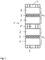
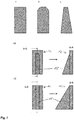
- FIG. 1 Further modifications of the pulverized coal burners for raw lignite fired steam generators are carried out mainly as register burners or as slot burners.
- the geometry of the burner depends essentially on the air and pulverized coal mass flows used.
- the applicant uses in the prior art three basic variants, one of which in FIG. 1 will be shown.
- the variant shown is equipped with two burner fingers, each burner finger having horizontal central core air pipes or nozzles.
- the burner fingers are horizontally limited by the lower air slot, intermediate air slot and upper air slot.
- the central core air pipes divide the burner finger into two burner half fingers and, in addition to participating in the combustion process, also cool the dust fingers when the burner is out of operation.
- the main secondary air flow is injected above, below and below the fuel jet.
- the distinguishing feature of this conventional burner is the horizontal stratification between coal dust flow and the main secondary airflow.
- This air staging on the one hand to the total fuel jet recirculation of hot flue gas, which is required for a reliable ignition.
- this air staging reduces the primary pollutant emissions, in particular nitrogen oxide formation, due to the reduction of the O 2 supply by a low air ratio (air / fuel ratio) in the burner belt area. Because of the horizontal stratification of combustion air and coal dust, a slow mixing of the two components is achieved.
- the technical object is achieved by a method for the combustion of solid, liquid or gaseous fuels, in particular pulverized coal, in which the fuel stream is introduced and burnt into a combustion chamber via one or more main burners, wherein the fuel stream of the respective main burner is introduced into the combustion chamber via a fuel slot or via a plurality of fuel slots arranged in a vertical plane, wherein additional burner air (secondary air) is introduced via louvers or air nozzles in the firebox; wherein a portion of the additional burner air is introduced into the combustion chamber by means of horizontally extending rows of louvers or air nozzles, the fuel flow being limited by the burner air introduced through these louvers or air nozzles above and below; optionally further burner air by means of one or more horizontally extending rows of louvers or Air nozzles is introduced into the combustion chamber, wherein the fuel flow is divided horizontally by this burner air;
- the other part of the burner air is introduced via unilaterally arranged air slots or air nozzles which extend at least over the entire vertical extent of all
- the term "stratification" means that at least two adjacent layers of mass flows are produced, for example, in the horizontal stratification, the alternating layers of burner airflow (eg injected via the top air nozzles, under air nozzles, intermediate air nozzles and center core air nozzles) and fuel flow, ie a line along the vertical happens different layers. In the vertical stratification, there are alternating layers of fuel flow and side air flow, ie a line along the horizontal passes through different layers.
- the term "grading" means that within a mass flow, ie within a layer of the fuel stream or an air stream, there is a different density of the particles. In a horizontal grading, or in a "radial grading" with respect to lying in a horizontal plane imaginary Feuernik, the concentration or density of the particles of the respective stream changes along a horizontal line. One could therefore speak of a horizontal gradient.
- louvers or air nozzles which extend over at least the entire vertical extent of all fuel slots of the main burner, is to be understood according to the invention that such by Siemensschlitze- or nozzles only on one side of the Brenners are arranged, and not on both sides.
- burner air or “secondary air” refers to the air that is introduced into the combustion chamber by means of separate air slots or air nozzles immediately adjacent to the fuel slots or fuel nozzles. If air is used as the carrier medium or part of it for the fuel, and thus introduced via the fuel slots or fuel nozzles, this is referred to as primary air.
- the additional burner air is introduced through horizontally extending rows of louvers or air nozzles in the firebox. These are arranged at least above the uppermost fuel slot and below the lower fuel slot. Thus, the fuel flow is limited by the burner air introduced through these horizontally extending rows of louvers or air nozzles above and below.
- Coal dust or preferably a pulverized coal / flue gas mixture is preferably introduced into the combustion chamber via the fuel slots.
- the burner air flow is introduced into the combustion chamber via lateral air slots or air nozzles, wherein the distance between the center of the air slot and the air nozzle to the adjacent edge of the fuel slot is at most 1 ⁇ 2 of the horizontal dimension of the fuel slot.
- a helical, ascending flow is built up in the combustion chamber, wherein preferably introduced via the lateral louvers or air nozzles in the combustion chamber burner air flow is introduced relative to the direction of rotation of the helical flow leading to the fuel flow.
- the vertical stratification between the fuel stream and the burner air stream is configured such that the layer of burner airflow passes between the wall of the furnace and the fuel stream, and the fuel stream passes between the burner air stream and the central longitudinal axis of the furnace.
- a method is preferred in which the ratio of the vertical extent to the horizontal extent of the layer of the fuel stream of a Main burner at the exit into the furnace at least 1.0: 1, preferably at least 1.5: 1, more preferably at least 2.0: 1, even more preferably at least 2.5: 1, more preferably at least 3.0: 1, still more preferably at least 3.5: 1 and more preferably at least 4.0: 1. These measures promote the formation of vertical stratification.
- further burner air is introduced into the combustion chamber by means of one or more horizontal rows of louvers or air nozzles, whereby the fuel flow is divided horizontally by this burner air.
- the amount of burner air introduced into the combustion chamber via the one or more horizontally extending rows of air slots or air nozzles increases in the direction of side air slots or side air nozzles.
- a radial air staging is generated.
- the air staging takes place on the burner from the furnace in the radial direction. This means that the side air is injected so that it forms a relative to the firing circle outside fog.
- the injected air quantity is increased in the direction of rotation of the combustion chamber flow (ie towards the outside).
- the radial air staging also provides a predominantly oxidizing atmosphere near the wall, which is an important criterion for suppressing corrosion. Oxygen, ie oxidizing conditions, on the wall prevent corrosion of the furnace walls.
- the burner air is introduced by means of one or more horizontally extending rows of louvers or air nozzles in the combustion chamber, wherein the fuel flow is limited above and below, and optionally divided horizontally.
- the amount of burner air introduced via these louvers or air nozzles increases from top to bottom, from bottom to top or from above and below in the direction of the center of the burner, ie it will be a generated vertical air grading. It is a vertical air staging, because along the vertical, the amount of injected air is varied.
- This vertical air staging is preferably done together with the above-described radial air staging for advantageous operation in the burner.
- different amounts of air are set in the sub-air, upper air and possibly intermediate air.
- the sidewall air can be varied over the height.
- the exact setting depends on the fuel properties, such as fineness, water content and reactivity, but also on the furnace geometry and flow.
- An advantageous setting can preferably be made so that the amount of air in the sub-air is set larger than in the intermediate air and the upper air. The reason for this is, depending on the reactivity of the coal and / or depending on the fineness of grinding, to increase the amount of under-air in order to reduce unburned particles falling into the hopper.
- the burner allows a two-dimensional air staging (in radial and vertical direction) to allow optimal adaptation to the current fuel.
- a radial fuel staging is performed, that is, the concentration of fuel flow increases along the horizontal, within the fuel flow along the horizontal from the side bounded by the side airflow to the opposite side.
- the particle density in the fuel stream increases.
- the radial fuel staging takes place counter to the direction of the radial air staging.
- the difference in the concentration of the fuel at the fuel outlet (of the fuel slot) at the edge facing the side air stream is at least 5% compared to the opposite edge.
- the design of the feed passage for the fuel outlet is carried out such that local local enrichment of the fuel particle stream takes place through the flow guide.
- the formation of primary NO x is thus further suppressed.
- the burner includes flow diversion means in the fuel slots or in the feed slots of the fuel slots to increase the concentration of fuel flow introduced through the fuel slots from the side of the side air slots or nozzles to the opposite side. In this case, a radial fuel staging is generated.
- These means of flow diversion in the fuel slots or their feed channels are selected from the group consisting of i) a one-sided taper of the feed channel, the taper being located in the feed channel on the side adjacent to the side air slots; ii) harassment; iii) steering flaps; iv) curvature of the feed channel.
- the particles are guided by flow deflection on the side of the burner, which is opposite to the side of the side air nozzles or the side air flow.
- the mixing of the combustion air is delayed in the carrier gas fuel stream and it forms a more extensive degassing.
- a zone of sub-stoichiometric combustion is formed.
- the air flow introduced via the lateral air slots or air nozzles is aligned such that it is introduced into the combustion chamber at an angle of 2 ° to 20 °, preferably 5 ° to 15 °, away from the orientation of the fuel flow becomes. This also delays the mixing of the combustion air into the carrier gas fuel stream, which leads to a reduction in the production of NO x .
- a further preferred measure results in a more extensive degassing zone with substoichiometric combustion, which leads to a reduction in the production of NO x .
- the fuel flow at an angle of 2 ° to 30 °, preferably from 5 ° to 15 °, with respect to the horizontal inclined downwards introduced into the furnace.
- the undefined ignition, the unequal distribution of the fuel and the undefined mixing of the combustion air and their negative effects on the NO x -emissons can be eliminated.
- the invention enables improved combustion with reduced NO x emissions by means of defined ignition, optimized air staging (radial and vertical), optimized combustion air interference in the carrier gas-dust jet and radial fuel staging.
- advantageous properties are achieved during operation by means of the above-mentioned measures, namely a reduction of local temperature peaks, and thereby a reduction of the slagging tendency and of the thermally formed NO x in the temperature peaks.
- an improvement of the wall atmosphere is effected by radial air curtain, whereby the tendency to corrosion of the furnace walls is reduced.
- the method according to the present invention leads to an optimization of the combustion process and to the reduction of the primary NO x emissions in the burner belt area.
- the combustion air is essentially radially stepped.
- the vertical stratification between coal dust flow and side air flow is the characterizing feature of the present invention.
- the superposition of the radial air staging in the combustor and the vertical air staging in the furnace (via top air nozzles) ensures an even slower mixing effect of the air into the fuel jet and thus additional suppression of the primary NO x formation.
- the side air at the burner supplies the nearest evaporator walls with combustion air, so that moderate flue gas temperatures and a comparatively high O 2 wall atmosphere occur there. This significantly minimizes the risk of both wall corrosion and slagging in the burner belt area.
- the upper, intermediate and sub-air is no longer introduced through slots, but through thermally stable tube constructions.
- the fuel flow is introduced tangentially into the combustion chamber via one or more main burners, the fuel flow or the partial fuel streams fed from a plurality of main burners being or being aligned with a combustion circuit in the combustion chamber.
- burn-out air is supplied to ensure the burn-out of the fuel introduced into the combustion chamber above the supply of the fuel stream.
- the combustion chamber has a rectangular, in particular a square cross-section, wherein the fuel flow in the form of a wall fire, preferably a Allwand85ung is introduced into the furnace.
- a furnace wherein two or more burners according to the invention are arranged side by side per firebox wall.
- two or more burners according to the invention are arranged one above the other per combustion chamber wall.
- a first plane at least one burner according to the invention is preferably arranged per firebox wall, and in a second plane likewise at least one burner according to the invention is disposed per firebox wall, wherein the second plane is arranged above the first plane.
- Each burner of a plane is aligned to a circle of fire, wherein the firing circle of the 1st level is offset to the firing circle of the 2nd level along the vertical.
- a furnace is used, wherein arranged in the furnace according to the described 1st and 2nd level further levels with the burners according to the invention.
- the inventive method for burning fuels leads to the reduction of nitrogen oxide pollution.
- lignite dust is introduced via main burner tangentially into a rectangular or square combustion chamber and air vertically layered also introduced into the furnace.
- combustion air is supplied to the implementation of the fuel above its supply.
- the supply of all reactants is done in such a way that a helical ascending flow is built up in the furnace. Due to the stepped supply of the reduction fuel, a combustion zone in the region of the main burners with substoichiometric combustion and a burn-out zone above the supply of the burn-out air are formed.
- an additional air flow in the form of a corner fire is introduced into the firebox.
- the fuel stream is passed to flame stabilizers (teeth) mounted directly on the fuel exit (coal dust exit) of the fuel slots.
- flame stabilizers will serve to stably ignite the coal dust / air mixture.
- the flame stabilizers serve to slow down the dust particles and create turbulence of the particles to accelerate the release of volatiles and to stabilize the ignition close to the exit of the burners.
- the obstruction of the free cross-section of the fuel slot is from 5% to 50%.
- the fuel stream is passed by ramps which are mounted directly on the fuel outlet of the fuel slots. These ramps serve to ensure the ignition of the fuel directly at the burner.
- the ramps increasingly narrow the burner feed channel towards the exit.
- the ramps provide a further increase in turbulence at the fuel outlet. They can be carried out either individually or together in combination with flame stabilizers.
- a burner for a firing system for introducing a fuel flow, in particular a pulverized coal stream into a combustion chamber of the firing plant, wherein the burner has a fuel slot or a plurality of fuel slots arranged in a vertical plane, wherein one or more horizontal rows of louvers or air nozzles are disposed at least above and below the fuel slots, wherein one side of the fuel slots air slots or air nozzles are arranged, which extend at least over the entire vertical extent of all the fuel slots of the burner; and wherein the burner in the fuel slots or their supply channels includes means for flow diversion to increase the concentration of the fuel flow introduced through the fuel slots from the side of the side air slots (11) to the opposite side, creating a radial fuel staging.
- the "one-sided" arrangement of the louvers or air nozzles means that such side louvers or nozzles are arranged only on one side of the burner or the fuel slots or nozzles, and not on both sides.
- the fuel slots preferably have a rectangular or square shape.
- the main burner is configured such that at least 20%, preferably at least 30%, at least 40%, at least 50%, at least 60%, at least 70%, at least 80%, at least 85%, at least 90%, at least 95% of the air flow introduced through the burner through the side louvers or air nozzles.
- the lateral air slots or air nozzles are arranged so that the distance between the center of the air slot or the air nozzle to the adjacent edge of the fuel slot is at most 1 ⁇ 2 the horizontal dimension of the fuel slot.
- the ratio of the vertical extent to the horizontal extent of the entirety of the fuel slots of the burner is at least 1.0: 1, preferably at least 1.5: 1, more preferably at least 2.0: 1, even more preferably at least 2 , 5: 1, more preferably at least 3.0: 1, even more preferably at least 3.5: 1 and most preferably at least 4.0: 1.
- the orientation of the lateral air slots or air nozzles is inclined by an angle of 2 ° to 20 °, preferably from 5 ° to 15 ° away from the fuel slots.
- burners wherein one or more horizontal rows of air slots or air nozzles are arranged between the fuel slots, for the horizontal subdivision of the fuel flow of a burner by means of burner air.
- the burner is configured so that the burner air is introduced by means of one or more horizontally extending rows of louvers or air nozzles in the firebox, wherein the fuel flow is divided horizontally and limited above and below, and in particular configured so that the over these louvers or air nozzles introduced amount of air increases toward 9.luftschlitze- or nozzles, with a radial air staging is generated.
- the burner is configured so that the burner air by means of one or more horizontally extending rows of louvers or air nozzles is introduced into the combustion chamber, wherein the fuel flow is divided horizontally and limited above and below, and in particular configured so that the introduced via these louvers or air nozzles amount of air from top to bottom, from bottom to top or from above and below towards the center of the burner, creating a vertical air staging.
- the undefined ignition, the unequal distribution of the fuel and the undefined mixing of the combustion air and its negative effects on the NO x -emissons can be eliminated.
- the invention provides an improved burner of the "jet burner” type with reduced NO x emissions by means of defined ignition, optimized air staging (radial and vertical), optimized combustion air mixing in the carrier gas-dust jet and radial fuel staging.
- the burner according to the invention achieves advantageous properties during operation by means of the abovementioned measures, namely a reduction of local temperature peaks, and thereby a reduction in the tendency to slag and the NO x thermally formed in the temperature peaks.
- an improvement of the wall atmosphere is effected by radial air curtain, whereby the tendency to corrosion of the furnace walls is reduced.
- flame stabilizers are attached to the ignition of the fuel at the outlets of the individual fuel slots. These flame stabilizers are used for stable ignition of the coal dust / air mixture. The stabilizers serve to slow down the dust particles and generate turbulence of the particles to accelerate the release of volatiles and to stabilize the ignition close to the exit of the burners. The flame stabilizers are attached to the fuel outlet of the fuel slots and protrude into the cross section of the fuel slot.
- the shape of the flame stabilizers is not limited.
- the flame stabilizers may have a rounded, rectangular or square shape.
- the different tooth shapes serve in principle the same purpose, namely by generating local turbulence to favor the ignition (flame holder).
- the flame stabilizers are provided with a support rib or stiffening rib on the side facing away from the firebox.
- This rib fulfills two main tasks, namely i) the stiffening of the flame stabilizer from a constructive point of view, and ii) the removal or dissipation of heat.
- the flame stabilizer is exposed to large thermal radiation from the furnace. Although cooling takes place by the continuous flow of carrier gas / fuel mixture. Nevertheless, the rib provides better heat dissipation. This is particularly important when the burner is out of operation, so no cooling is done by the carrier gas / fuel mixture. In the case where the burner is out of operation, then usually abandoned amounts of cooling air are comparatively small, so that the improved heat dissipation through the rib is required.
- the flame stabilizers may be placed on all edges of the exit of the rectangular or square fuel slot, i) on the upper horizontal; ii) at the lower horizontal; iii) at the vertical to the side air; iv) on the vertical side air. It is also possible not to equip individual edges with flame stabilizers.
- the flame stabilizers are placed at the following edges of the exit of the rectangular or square fuel slot: i) at the upper horizontal; ii) at the lower horizontal; iii) at the vertical adjacent to the side air jets; iv) at the vertical relative to the soluftdüsen- or -Schlitzen, particularly preferably in particular at the vertical relative to the Soluftdüsen- or Slots.
- the flame stabilizers are attached to the vertical adjacent to the side air nozzle slots throughout, while the flame stabilizers are distributed across the entire edge adjacent to the upper horizontal and lower horizontal towards the edge the soluftdüsen- or -Schlitzen not continuously attached. This situation will be in FIG. 9B shown.
- a smaller blockage is possible.
- a larger blockage is necessary in order to further increase the interspace velocity and thus the turbulence.
- the obstruction of the free cross-section of the carrier gas-dust outlet nozzle of 5% to 50%.
- ramps are preferably attached to the fuel outlet, which increasingly narrow the burner inlet channel in the direction of exit.
- the ramps provide a further increase in turbulence at the fuel outlet. They can be carried out either individually or together in combination with flame stabilizers.
- the ramps can also be mounted horizontally and vertically at the coal dust outlet. In FIG. 11 an application example of the ramps is shown. The ramps are in this case individually and attached to the horizontally extending edges of the fuel outlet.
- the technical object is further achieved by a firing system for the combustion of solid, liquid or gaseous fuels, in particular pulverized coal, wherein at least one burner per combustion chamber wall according to the present invention, as described above, is arranged and aligned these burners tangentially to a combustion circuit in the furnace are.
- the main burners used in the furnace have a fuel slot or a plurality of fuel slots arranged in a vertical plane, wherein one or more horizontal rows of louvers or air nozzles are arranged at least above and below the fuel slots, for limiting the flow of fuel up and down by means of burner air, wherein one side of the fuel slots air slots or air nozzles are arranged, which extend at least over the entire vertical extent of all fuel slots of the burner, for introducing burner air into the combustion chamber and for the vertical limitation of the fuel flow on one side by means of the burner air; and wherein the burner in the fuel slots or their supply channels includes means for flow diversion to increase the concentration of the fuel flow introduced through the fuel slots from the side of the side air slots or nozzles to the opposite side, creating a radial fuel staging.
- the firing system has a rectangular, in particular a square cross-section, wherein at least one wall, preferably at least two opposite walls, more preferably all walls of the firebox are each equipped with at least one main burner, preferably two juxtaposed main burners.
- the burners are tangentially aligned with a combustion circuit in the combustion chamber.
- the furnace is configured so that when operating in the furnace a helical, ascending flow is established, based on the sense of rotation of the helical Flow of the introduced via the side louvers or air nozzles in the combustion chamber side air flow leading to the fuel flow is introduced.
- the vertical stratification between fuel flow and side airflow be constructed such that the layer of side airflow passes between the wall of the firebox and the fuel stream, and the fuel stream runs between the side airflow and the central longitudinal axis of the firebox.
- the burners are preferably oriented at an angle of 2 ° to 30 °, preferably from 5 ° to 15 °, with respect to the horizontal inclined downwards.
- two or more burners according to the invention are arranged next to one another per combustion chamber wall. In another preferred embodiment, two or more burners according to the invention are arranged one above the other per combustion chamber wall.
- At least one burner according to the invention is preferably arranged per firebox wall, and in a second plane likewise at least one burner according to the invention is disposed per firebox wall, wherein the second plane is arranged above the first plane.
- Each burner of a plane is aligned to a circle of fire, wherein the firing circle of the 1st level is offset to the firing circle of the 2nd level along the vertical.
- additional levels with the burners according to the invention are arranged in the furnace according to the described 1st or 2nd level.
- at least two burners according to the invention are arranged side by side per firebox wall.
- two or more burners according to the invention are arranged side by side per firebox wall, and preferably also in a second plane, two or more burners according to the invention are arranged above the first plane.
- Each burner is one level on a circle of fire aligned, with the firing circle of the 1st level is offset to the firing circle of the 2nd level along the vertical.
- additional levels with the burners according to the invention are arranged in the furnace according to the described 1st or 2nd level.
- the main burner (s) are configured such that at least 20%, preferably at least 30%, at least 40%, at least 50%, at least 60%, at least 70%, at least 80%, at least 85%, at least 90%, at least 95% of the airflow introduced via a main burner is introduced into the combustion chamber via the side louvers or air nozzles so as to create a vertical stratification between fuel flow and side air flow.
- the lateral louvers or air nozzles arranged so that the distance between the center of the louver and the air nozzle to the adjacent edge of the fuel slot is at most 1 ⁇ 2 the horizontal dimension of the fuel slot.
- the ratio of the vertical extent to the horizontal extent of the entirety of the fuel slots of a main burner exiting the furnace is at least 1.0: 1, preferably at least 1.5: 1, at least 2.0 : 1, at least 2.5: 1, more preferably at least 3.0: 1 and even more preferably at least 3.5: 1 and most preferably at least 4.0: 1.
- this is configured so that the burner air is introduced by means of one or more horizontally extending rows of louvers or air nozzles in the furnace, the fuel flow is divided horizontally and limited above and below, and in particular configured in that the amount of air introduced via these air vents increases in the direction of side air vents or nozzles, creating a radial air staging.
- this is configured so that the burner air is introduced by means of one or more horizontally extending rows of louvers or air nozzles in the furnace, the fuel flow is divided horizontally and limited above and below, and in particular configured so that the amount of air introduced through these louvers or air nozzles increases from top to bottom, from bottom to top, or from top to bottom toward the center of the burner, creating a vertical air staging.
- burn-out air nozzles for introducing burn-out air into the furnace are arranged above the main burners.
- additional air nozzles are arranged in the corners of the firebox, which is also referred to as corner firing.
- flame stabilizers are attached to the ignition of the fuel at the outlets of the individual fuel slots.
- These flame stabilizers serve to stably ignite the coal dust / air mixture.
- the stabilizers serve to slow down the dust particles and create turbulence of the particles to accelerate the release of volatiles and to stabilize the ignition close to the exit of the burners.
- the shape of the flame stabilizers is not limited.
- the flame stabilizers may have a rounded, rectangular or square shape.
- the fuel slots in the furnace around the entire edge of the exit of the fuel slots around flame stabilizers.
- the in FIG. 1 illustrated conventional burner 1 has two burner fingers, an upper burner finger 1a and a lower burner fingers 1b.
- the fuel slots are designated 2. Rows of central core air tubes 3 divide the burner fingers horizontally into two half-fingers each. Between the upper burner finger and the lower burner finger, an intermediate air slot 5 is arranged, while an upper air slot 4, the fuel slots up and an under air slot 6, the fuel slots down limited.
- the main secondary air flow is injected above, below and below the fuel flow.
- This type of burner of the prior art is characterized by the horizontal stratification of coal dust flow and main secondary air flow.
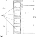
- the in FIG. 2 shown burner 1 represents an embodiment of the present invention.
- the in FIG. 2 The embodiment shown has two burner fingers, an upper burner finger 1a and a lower burner finger 1b.
- the fuel slots are designated 2.
- the individual fuel slots 2 are separated from one another by rows of center core air nozzles 9 or intermediate air nozzles 13.
- a series of top air nozzles 8 limits the fuel slots 2 upwards and a row of under air nozzles 10 down the fuel slots.
- air slots or air nozzles 11 are arranged according to the present invention. These extend at least over the entire vertical extension of the burner 1 and serve to supply side air.
- the burner 1 is configured so that at least 20% of the air flow introduced through the burner is introduced into the furnace via the side air slots 11 or air nozzles to create a vertical stratification between fuel flow and main secondary air flow.
- the lateral louvers 11 or air nozzles are preferably arranged. that the Distance between the center of the louver 11 to the adjacent edge of the fuel slot 2 is at most 1 ⁇ 2 of the horizontal dimension of the fuel slot 2.
- a helical, ascending flow is built up in the furnace. Based on the direction of rotation of the helical flow, the side airflow directed via the lateral air slots 11 is introduced into the combustion chamber leading to the fuel flow.
- the vertical stratification of fuel flow and side airflow according to the present invention is such that the layer of side airflow passes between the wall of the furnace and the fuel stream, and the fuel stream runs between the side airflow and the central longitudinal axis of the furnace.
- the vertical extent of the fuel slots of the burner at the outlet into the combustion chamber is preferably a multiple to the horizontal extent of the fuel slots, namely here about factor 4.
- flame stabilizers 12 are attached to the ignition of the fuel at the outlets of the individual fuel slots. These flame stabilizers are used for stable ignition of the coal dust / air mixture.
- the flame stabilizers are attached to the fuel outlet of the fuel slots 2 and protrude into the cross section of the fuel slot.
- flame holders 12 are mounted along all four edges of the fuel slots 2.
- FIG. 3 For example, the radial air staging of the burner set in a preferred method according to the present invention will be explained.
- a portion of the burner air is introduced by means of one or more horizontally extending rows of air nozzles 8, 9, 10 in the furnace. Characterized the introduced through the fuel slots 2 fuel flow is divided horizontally and limited above and below.
- the over these air nozzles 8, 9, 10 introduced Air quantity in the direction of soluftschlitze- or nozzles 11 toward, ie it is a radial air staging generated.
- the air in the side is injected in such a way that it forms a veil on the outside of the circle of fire.
- the quantity of air injected via the horizontally extending rows of burner air nozzles 8, 9, 10 is increased in the direction of rotation of the combustion chamber flow (that is, toward the outside or in the direction of side air nozzles 11).
- the increasing amount of air or radial air grading is shown schematically by the wedge at the top of the figure.
- two flame stabilizers 12 are attached to only three edges of the fuel slots 2 at the exit of the fuel slots 2.
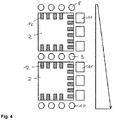
- FIG. 4 For example, the vertical air staging of the burner set in a preferred method according to the present invention will be explained.
- the burner air is introduced by means of one or more horizontally extending rows of air nozzles 8, 9, 10 in the furnace. In this way, the introduced through the fuel slots 2 fuel flow is divided horizontally and limited above and below.
- the amount of air introduced via these air nozzles 11 from top to bottom is shown schematically by the bar on the right side of the figure.
- FIG. 5 shows in the left part of the figure, the burner level seen from the firebox.
- the right part of the figure represents a sectional view along the drawn in the left part of the figure CC level.
- the side air nozzle is shown at 11. In a preferred embodiment, the axis of the side air nozzle 11 is inclined away from the axis of the fuel supply channel 2. In the radial fuel staging, the fuel flow increases from the side airflow side to the opposite side.
- the design of the feed channel 2 to the burner is designed so that a local accumulation of the fuel particle stream is carried out by the flow guide. This can be achieved, for example, with a beginning of a shoulder 20 narrowing of the fuel supply channel 2, which is arranged on the side of the fuel supply channel, which is adjacent to the side air duct 11.
- the particles are guided by flow deflection on the side of the burner, which is opposite to the side of the side air nozzles or the side air flow.
- the radial fuel staging is shown schematically by the bar on the lower side of the figure.
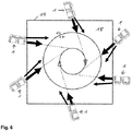
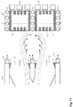
- FIG. 6 is a cross-sectional view of a combustion chamber 18 in a schematic representation with identification of the flow directions of the introduced into the combustion chamber 18 fuel (thick arrow) and injected into the firebox side air (thin arrow) shown.
- the burners 1 are designed to be identical to one another and the burners are illustrated by their burner mirrors 1 as an example. Downstream of the burner creates an air curtain on the burner wall.
- the arrangement of the burner on the combustion chamber 18 follows here the principle of tangential firing.
- the burners 1 fire from the wall 14 (or corners) FIG. 6 not shown) tangent to an imaginary circle, the so-called Brenn Vietnamese or Feuernik.
- the vertical stratification between fuel flow and side airflow is configured such that the side airflow layer between the wall of the furnace and the fuel stream, and the fuel flow between the side airflow and the central longitudinal axis of the fuel Firebox runs.
- FIG. 6 is further illustrated schematically by means of the solid arrows coming from the direction of the burner, that in preferred embodiments, the axis of the side air flow (thin arrow) from the axis of the fuel flow (thick arrow) is inclined away.
- flame stabilizers in front view
- flame stabilizers are attached to the outlets of the individual fuel slots to ignite the fuel.
- These flame stabilizers are used for stable ignition of the coal dust / air mixture.
- the stabilizers serve to slow down the dust particles and generate turbulence of the particles to accelerate the release of volatiles and to stabilize the ignition close to the exit of the burners.
- the shape of the flame stabilizers is not limited.
- the flame stabilizers may have a rounded, rectangular or square shape.
- the flame stabilizers 12 are shown in the subfigures a1 and a2 further embodiments of the flame stabilizers 12 are shown.
- the flame stabilizers 12 are provided with a support rib or stiffening rib 15 on the side facing away from the firebox. This rib is used for stiffening from a constructive point of view and the dissipation of heat.
- FIG. 8 Further embodiments of the flame stabilizers 12 are shown. Again, the flame stabilizers 12 are provided with a support rib or stiffening rib 15 on the side remote from the firebox.
- the flame stabilizers 12 may be disposed on all edges of the exit of the rectangular or square fuel slot 2: at the upper edge; at the bottom edge; at the vertical edge adjacent to the side air; on the vertical edge opposite the side air. It is also possible not to provide individual edges with flame stabilizers as shown in FIGS. 9A and 9B will be shown.
- the flame stabilizers 12 are continuous to the upper and lower horizontal mounted distributed over the entire edge, while the flame stabilizers 12 are not continuously distributed at the vertical adjacent to the 9.luftdüsen- or -Slitzen 11 ( FIG.
- the flame stabilizers 12 are mounted on the vertical adjacent to the side air nozzle slots 11 throughout the same throughout the edge, while the flame stabilizers 12 are adjacent to the upper horizontal and lower horizontal towards the edge the soluftdüsen- or -Schlitzen are not distributed throughout ( FIG. 9B) ,
- FIG. 10 shows an embodiment in which flame stabilizers 12 of different geometries are attached to a fuel outlet 2.
- FIG. 11 shows the operation of ramps 7 at the exits of the fuel nozzles.
- the left part of the figure shows a section along the registered in the right part of the axis AA.
- a portion of the burner air is introduced by means of one or more horizontally extending rows of air nozzles 8, 9, 10 in the furnace.
- the fuel flow is divided horizontally and limited above and below.
- ramps 7 are preferably attached to the fuel outlet 2. These ramps 7 provide a further increase in turbulence at the fuel outlet (shown in the left part of the figure).
- the figure shows an embodiment in which the ramps 7 are mounted on the upper and lower edges, while the flame stabilizers 12 are arranged only on the vertical edges.
- the burner type according to the present invention leads to an optimization of the combustion process and to the reduction of the primary NO x emissions in the burner belt area.
- the combustion air is essentially stepped radially.
- the characterizing feature of the present invention is the vertical stratification between coal dust flow and side air flow. The superimposition of the radial air staging in the burner and the vertical air staging in the combustion chamber (via top air nozzles) still ensures slower mixing effect of the air in the fuel jet and thus an additional suppression of primary NO x formation.
- the side air at the burner supplies the nearby evaporator walls with combustion air, so that there moderate flue gas temperatures and a relatively high O 2 wall atmosphere prevail.
- the furnace or the burner according to the present invention form in the furnace from bottom to top, a main burner combustion zone and the application of burnout air supply a burn-out.
- a tangential firing is used with a plurality of main burners aligned on a combustor, and preferably a plurality of burnout air nozzles located above the main burners.
Landscapes
- Engineering & Computer Science (AREA)
- Chemical & Material Sciences (AREA)
- Combustion & Propulsion (AREA)
- Mechanical Engineering (AREA)
- General Engineering & Computer Science (AREA)
Claims (15)
- Procédé de combustion de combustibles solides, liquides ou gazeux, en particulier de charbon pulvérisé, dans lequel le flux de combustible est introduit et brûlé dans une chambre de combustion (18) via un ou plusieurs brûleurs principaux (1), dans lequel le flux de combustible du brûleur principal (1) respectif est introduit dans la chambre de combustion (18) via une fente de combustible (2) ou via plusieurs fentes de combustible (2) agencées dans un plan vertical,
dans lequel de l'air de brûleur supplémentaire est introduit dans la chambre de combustion (18) via des fentes de passage d'air ou des buses d'air (8, 9, 10, 11) ;
dans lequel une partie de l'air de brûleur supplémentaire est introduite dans la chambre de combustion (18) au moyen de rangées de fentes de passage d'air ou de buses d'air (8, 9, 10) s'étendant horizontalement,
dans lequel le flux de combustible est confiné au-dessus et au-dessous de l'air de brûleur introduit via ces fentes de passage d'air ou buses d'air (8, 9, 10) ;
dans lequel facultativement de l'air de brûleur supplémentaire est introduit dans la chambre de combustion (18) au moyen d'une ou plusieurs rangées de fentes de passage d'air ou de buses d'air (9) s'étendant horizontalement, dans lequel le flux de combustible est divisé horizontalement par cet air de brûleur ;
dans lequel l'autre partie de l'air de brûleur est introduite dans la chambre de combustion (18) par des fentes de passage d'air ou des buses d'air (11) agencées d'un côté, qui s'étendent au moins sur toute l'étendue verticale de toutes les fentes de combustible (2) du brûleur principal (1), et le flux de combustible du brûleur principal respectif (1) est confiné verticalement d'un côté et un flux d'air latéral est réalisé ;
caractérisé en ce qu'au moins 20 % de l'air de brûleur introduit via un brûleur principal (1) est introduit dans la chambre de combustion (18) via les fentes de passage d'air ou buses d'air (11) latérales du brûleur principal (1), de sorte qu'une stratification verticale entre le flux de combustible et le flux d'air de brûleur est générée ; et
en ce que la concentration du flux de combustible dans le flux de combustible augmente à partir du côté du flux d'air latéral vers le côté opposé, dans lequel un étagement de flux de combustible radial est généré. - Procédé selon la revendication 1, caractérisé en ce qu'au moins 30 %, de préférence au moins 40 %, au moins 50 %, au moins 60 %, au moins 70 %, au moins 80 %, au moins 85 %, au moins 90 %, au moins 95 % du flux d'air introduit via le brûleur principal (1) s'écoule par les fentes de passage d'air ou buses d'air (11) latérales du brûleur principal (1).
- Procédé selon la revendication 1 ou 2, caractérisé en ce qu'un flux ascendant hélicoïdal est établi dans la chambre de combustion (18), et dans lequel le flux d'air de brûleur introduit dans la chambre de combustion (18) via les fentes de passage d'air ou buses d'air (11) latérales par rapport au sens de rotation du flux hélicoïdal est introduit en avance par rapport au flux de combustible.
- Procédé selon l'une quelconque des revendications 1 à 3, caractérisé en ce que la quantité de l'air de brûleur introduite via les une ou plusieurs rangées de fentes de passage d'air ou de buses d'air (8, 9, 10) s'étendant horizontalement augmente dans la direction des fentes de passage d'air ou des buses d'air (11) latérales, dans lequel un étagement d'air radial est généré.
- Procédé selon l'une quelconque des revendications 1 à 4, caractérisé en ce que la quantité d'air de brûleur introduite via les fentes de passage d'air ou les buses d'air (8, 9, 10, 11)augmente de haut en bas, de bas en haut ou du haut du bas dans la direction du milieu du brûleur (1), dans lequel un étagement d'air vertical est généré.
- Brûleur (1) pour une installation de combustion permettant d'introduire un flux de combustible, en particulier un flux de charbon pulvérisé, dans une chambre de combustion (18) de l'installation de combustion,
dans lequel le brûleur (1) présente une fente de combustible (2) ou plusieurs fentes de combustible (2) agencées dans un plan vertical,
dans lequel une ou plusieurs rangées horizontales de fentes de passage d'air ou de buses d'air (8, 9, 10) sont agencées au moins au-dessus et au-dessous des fentes de combustible (2),
dans lequel des fentes de passages d'air ou des buses d'air (11) sont agencées d'un côté des fentes de combustible (2), qui s'étendent au moins sur toute l'étendue verticale de toutes les fentes de combustible (2) du brûleur (1) ; et caractérisé en ce que
le brûleur (1), dans les fentes de combustible (2) ou leurs canaux d'alimentation, contient des moyens de déviation de flux (20), pour augmenter la concentration du flux de combustible introduit par les fentes de combustible (2) depuis le côté des fentes de passage d'air ou des buses d'air (11) latérales vers le côté opposé, dans lequel un étagement de combustible radial est généré. - Brûleur (1) pour une installation de combustion selon la revendication 6, caractérisé en ce que les moyens de déviation de flux (20) dans les fentes de combustible (2) ou leurs canaux d'alimentation sont sélectionnés à partir du groupe constitué pari) un rétrécissement d'un côté du canal d'alimentation (20) ;ii) des chicanes ;iii) des volets de direction ;iv) une incurvation du canal d'alimentation.
- Brûleur (1) pour une installation de combustion selon la revendication 6 ou 7, caractérisé en ce que les fentes de passage d'air ou buses d'air (11) latérales sont agencées de sorte que la distance entre le point médian de la fente de passage d'air ou de la buse d'air (11) par rapport à un bord adjacent de la fente de combustible (2) est au plus égale à ½ de la dimension horizontale de la fente de combustible (2).
- Brûleur (1) pour une installation de combustion selon l'une quelconque des revendications 6 à 8, caractérisé en ce que l'orientation des fentes de passage d'air ou des buses d'air (11) latérales est inclinée en s'éloignant des fentes de combustion (2) selon un angle de 2° à 20°, de préférence de 5° à 15°.
- Brûleur (1) pour une installation de combustion selon l'une quelconque des revendications 6 à 9, caractérisé en ce que des stabilisateurs de flamme (12) sont montés au niveau de la sortie de combustible (19) des fentes de combustible (2) et font saillie dans la section transversale de la fente de combustible (2).
- Installation de combustion pour brûler des combustibles solides, liquides ou gazeux, en particulier du charbon pulvérisé, dans laquelle au moins un brûleur (1) selon les revendications 6 à 10 est agencé par paroi de chambre de combustion (14), et ces brûleurs (1) sont orientés de manière tangentielle sur un circuit de combustion dans la chambre de combustion (18).
- Installation de combustion selon la revendication 11, caractérisée en ce que les brûleurs (1) sont orientés inclinés vers le bas selon un angle de 2° à 30°, de préférence de 5° à 15°, par rapport à l'horizontale.
- Installation de combustion selon la revendication 11 ou 12, caractérisée en ce que deux brûleurs (1) ou plus selon les revendications 6 à 10 sont agencés côte à côte par paroi de chambre de combustion (14).
- Installation de combustion selon l'une quelconque des revendications 11 à 13, caractérisée en ce que deux brûleurs (1) ou plus selon les revendications 6 à 10 sont agencés de manière superposée par paroi de chambre de combustion (14).
- Installation de combustion selon l'une quelconque des revendications 11 à 14, caractérisée en ce que des buses d'air comburant sont agencées au-dessus du brûleur principal (1) pour introduire de l'air comburant dans la chambre de combustion (18).
Priority Applications (3)
| Application Number | Priority Date | Filing Date | Title |
|---|---|---|---|
| EP16164523.9A EP3228935B1 (fr) | 2016-04-08 | 2016-04-08 | Procédé de combustion pauvre en oxyde d'azote de combustibles gazeux, solides ou liquides, en particulier de poussière de charbon, brûleur et installation de combustion destinée a exécuter le procédé |
| PL16164523T PL3228935T3 (pl) | 2016-04-08 | 2016-04-08 | Sposób spalania z niską emisję tlenków azotu paliw stałych, ciekłych lub gazowych, zwłaszcza pyłu węglowego, palnik oraz instalacja paleniskowa do przeprowadzania sposobu |
| PCT/EP2017/058301 WO2017174751A1 (fr) | 2016-04-08 | 2017-04-06 | Procédé de combustion à faible taux en émissions d'oxyde d'azote de combustibles solides, liquides ou gazeux, en particulier de charbon pulvérisé, brûleur et installation de chauffe pour mettre ledit procédé en oeuvre |
Applications Claiming Priority (1)
| Application Number | Priority Date | Filing Date | Title |
|---|---|---|---|
| EP16164523.9A EP3228935B1 (fr) | 2016-04-08 | 2016-04-08 | Procédé de combustion pauvre en oxyde d'azote de combustibles gazeux, solides ou liquides, en particulier de poussière de charbon, brûleur et installation de combustion destinée a exécuter le procédé |
Publications (2)
| Publication Number | Publication Date |
|---|---|
| EP3228935A1 EP3228935A1 (fr) | 2017-10-11 |
| EP3228935B1 true EP3228935B1 (fr) | 2019-10-16 |
Family
ID=55701860
Family Applications (1)
| Application Number | Title | Priority Date | Filing Date |
|---|---|---|---|
| EP16164523.9A Active EP3228935B1 (fr) | 2016-04-08 | 2016-04-08 | Procédé de combustion pauvre en oxyde d'azote de combustibles gazeux, solides ou liquides, en particulier de poussière de charbon, brûleur et installation de combustion destinée a exécuter le procédé |
Country Status (3)
| Country | Link |
|---|---|
| EP (1) | EP3228935B1 (fr) |
| PL (1) | PL3228935T3 (fr) |
| WO (1) | WO2017174751A1 (fr) |
Families Citing this family (1)
| Publication number | Priority date | Publication date | Assignee | Title |
|---|---|---|---|---|
| CN111156501B (zh) * | 2020-01-02 | 2023-05-30 | 袁东辉 | 中心筒、形成中心筒的方法、分离器、循环流化床锅炉 |
Family Cites Families (15)
| Publication number | Priority date | Publication date | Assignee | Title |
|---|---|---|---|---|
| DE890254C (de) * | 1950-03-05 | 1953-09-17 | Kohlenscheidungs Ges M B H | Verfahren und Einrichtung zum Betrieb von Kohlenstaubfeuerungen fuer Hochleistungs-Dampfkessel |
| US4294178A (en) * | 1979-07-12 | 1981-10-13 | Combustion Engineering, Inc. | Tangential firing system |
| DE2933528A1 (de) | 1979-08-18 | 1981-03-26 | Deutsche Babcock AG, 46049 Oberhausen | Vorrichtung zum abtrennen von brueden |
| DE3531571A1 (de) | 1985-09-04 | 1987-03-05 | Steinmueller Gmbh L & C | Verfahren zum verfeuern von brennstoffen unter reduzierung der stickoxidbelastung und feuerung zur durchfuehrung des verfahrens |
| DE3731271C2 (de) | 1987-09-17 | 1996-09-05 | Babcock Energie Umwelt | Vorrichtung und Verfahren zum Verfeuern hochballasthaltiger Braunkohle |
| DE3920798A1 (de) * | 1989-06-24 | 1991-01-10 | Balcke Duerr Ag | Vorrichtung zur verbrennung von brennstoffen in einer brennkammer |
| US5020454A (en) * | 1990-10-31 | 1991-06-04 | Combustion Engineering, Inc. | Clustered concentric tangential firing system |
| US5799594A (en) * | 1993-11-08 | 1998-09-01 | Ivo International Oy | Method and apparatus for reducing nitrogen oxide emissions from burning pulverized fuel |
| DE4407198A1 (de) | 1994-03-04 | 1995-09-07 | Lentjes Kraftwerkstechnik | Braunkohlenbrenner |
| DE19514302C2 (de) | 1995-04-25 | 2001-11-29 | Alstom Power Boiler Gmbh | Verfahren und Feuerungssystem zur stickoxidarmen Wärmeerzeugung |
| US6138588A (en) * | 1999-08-10 | 2000-10-31 | Abb Alstom Power Inc. | Method of operating a coal-fired furnace to control the flow of combustion products |
| DE10301316B3 (de) * | 2003-01-15 | 2004-08-05 | Alstom Power Boiler Gmbh | Verfahren und Vorrichtung zum NOx-armen Verbrennen von Brennstoffstaub |
| CN2763701Y (zh) * | 2005-02-25 | 2006-03-08 | 贾臻 | 预热型煤粉燃烧器 |
| EP1731832A1 (fr) | 2005-06-11 | 2006-12-13 | Vattenfall Europe Generation AG & Co. KG | Arrangement d'un brûleur à jet pour la combustion du charbon pulvérisé dans une chambre de combustion à émission réduite de NOx |
| CN103134049B (zh) * | 2011-11-22 | 2015-09-30 | 中国科学院过程工程研究所 | 一种多角切圆多尺度煤粉解耦燃烧装置及其解耦燃烧方法 |
-
2016
- 2016-04-08 PL PL16164523T patent/PL3228935T3/pl unknown
- 2016-04-08 EP EP16164523.9A patent/EP3228935B1/fr active Active
-
2017
- 2017-04-06 WO PCT/EP2017/058301 patent/WO2017174751A1/fr active Application Filing
Non-Patent Citations (1)
| Title |
|---|
| None * |
Also Published As
| Publication number | Publication date |
|---|---|
| EP3228935A1 (fr) | 2017-10-11 |
| WO2017174751A1 (fr) | 2017-10-12 |
| PL3228935T3 (pl) | 2020-05-18 |
Similar Documents
| Publication | Publication Date | Title |
|---|---|---|
| DE3306483C2 (fr) | ||
| DE69735965T2 (de) | Brenner | |
| DE69923797T2 (de) | Verfahren zum betrieb eines tangentialen feuerungssystems | |
| DE3330373C2 (de) | Verfahren und Vorrichtung zum Verbrennen von Kohle | |
| EP3789672B1 (fr) | Installation de chauffage à la biomasse ayant une conduite d'air secondaire, ainsi que ses parties intégrantes | |
| EP3789673B1 (fr) | Installation de chauffage à biomasse à traitement optimisé des gaz de fumée | |
| DE2658847A1 (de) | Brennereinrichtung | |
| WO2021043895A1 (fr) | Installation de chauffage à biomasse comportant un traitement optimisé des gaz de combustion | |
| DE102011110842A1 (de) | Vorrichtung und Verfahren zur thermischen Behandlung von stückigem oder agglomeriertem Material | |
| EP1754937B1 (fr) | Tête de brûleur et procédé pour brûler du combustible | |
| DE60120787T2 (de) | Kombiniertes wirbelbett- und kohlenstaubverbrennungsverfahren | |
| EP2691701B1 (fr) | Procédé d'optimisation de la combustion totale des gaz d'échappement d'une installation de combustion | |
| EP3228935B1 (fr) | Procédé de combustion pauvre en oxyde d'azote de combustibles gazeux, solides ou liquides, en particulier de poussière de charbon, brûleur et installation de combustion destinée a exécuter le procédé | |
| DE2534438A1 (de) | Verfahren und vorrichtung zur kalzinierung von zementmaterial | |
| DE102004059679B4 (de) | Rundbrenner zur Verbrennung von staubförmigem Brennstoff | |
| EP1352197B1 (fr) | Bruleur pour la combustion de combustible pulverulent | |
| EP1026465B1 (fr) | Installation pour le traitement thermique de matières premières en poudre | |
| DE3434970A1 (de) | Einrichtung zur minderung der feststoffpartikel- und schadstoff-anteile im zwangsgefoerderten abgasstrom aus der verbrennung von kohlenstoffhaltigen feststoffen in einem reaktorbett | |
| DE589261C (de) | Vorrichtung zur unvollstaendigen Verbrennung pulverfoermigen Brennstoffes mit schleifenfoermiger Flammenfuehrung in einer Kammer | |
| DE4407198A1 (de) | Braunkohlenbrenner | |
| DE2816674B2 (de) | Kohlenstaubbrenner | |
| DD284742A5 (de) | Verfahren und anlage fuer eine fluidisierte verbrennung von festen brennstoffen | |
| DE3026516A1 (de) | Heissgaserzeuger | |
| DE19939672B4 (de) | Feuerungssystem sowie Verfahren zur Wärmeerzeugung durch Verbrennung | |
| DE10114094C2 (de) | Verfahren zum Verbrennen von staubförmigen Brennstoff in einem Kraftwerkskessel |
Legal Events
| Date | Code | Title | Description |
|---|---|---|---|
| PUAI | Public reference made under article 153(3) epc to a published international application that has entered the european phase |
Free format text: ORIGINAL CODE: 0009012 |
|
| STAA | Information on the status of an ep patent application or granted ep patent |
Free format text: STATUS: THE APPLICATION HAS BEEN PUBLISHED |
|
| AK | Designated contracting states |
Kind code of ref document: A1 Designated state(s): AL AT BE BG CH CY CZ DE DK EE ES FI FR GB GR HR HU IE IS IT LI LT LU LV MC MK MT NL NO PL PT RO RS SE SI SK SM TR |
|
| AX | Request for extension of the european patent |
Extension state: BA ME |
|
| STAA | Information on the status of an ep patent application or granted ep patent |
Free format text: STATUS: REQUEST FOR EXAMINATION WAS MADE |
|
| 17P | Request for examination filed |
Effective date: 20180328 |
|
| RAX | Requested extension states of the european patent have changed |
Extension state: BA Payment date: 20180328 Extension state: ME Payment date: 20180328 |
|
| RBV | Designated contracting states (corrected) |
Designated state(s): AL AT BE BG CH CY CZ DE DK EE ES FI FR GB GR HR HU IE IS IT LI LT LU LV MC MK MT NL NO PL PT RO RS SE SI SK SM TR |
|
| GRAP | Despatch of communication of intention to grant a patent |
Free format text: ORIGINAL CODE: EPIDOSNIGR1 |
|
| STAA | Information on the status of an ep patent application or granted ep patent |
Free format text: STATUS: GRANT OF PATENT IS INTENDED |
|
| INTG | Intention to grant announced |
Effective date: 20190423 |
|
| GRAS | Grant fee paid |
Free format text: ORIGINAL CODE: EPIDOSNIGR3 |
|
| GRAA | (expected) grant |
Free format text: ORIGINAL CODE: 0009210 |
|
| STAA | Information on the status of an ep patent application or granted ep patent |
Free format text: STATUS: THE PATENT HAS BEEN GRANTED |
|
| AK | Designated contracting states |
Kind code of ref document: B1 Designated state(s): AL AT BE BG CH CY CZ DE DK EE ES FI FR GB GR HR HU IE IS IT LI LT LU LV MC MK MT NL NO PL PT RO RS SE SI SK SM TR |
|
| AX | Request for extension of the european patent |
Extension state: BA ME |
|
| REG | Reference to a national code |
Ref country code: GB Ref legal event code: FG4D Free format text: NOT ENGLISH |
|
| REG | Reference to a national code |
Ref country code: CH Ref legal event code: EP |
|
| REG | Reference to a national code |
Ref country code: DE Ref legal event code: R096 Ref document number: 502016007083 Country of ref document: DE |
|
| REG | Reference to a national code |
Ref country code: IE Ref legal event code: FG4D Free format text: LANGUAGE OF EP DOCUMENT: GERMAN |
|
| REG | Reference to a national code |
Ref country code: AT Ref legal event code: REF Ref document number: 1191639 Country of ref document: AT Kind code of ref document: T Effective date: 20191115 |
|
| REG | Reference to a national code |
Ref country code: NL Ref legal event code: MP Effective date: 20191016 |
|
| REG | Reference to a national code |
Ref country code: LT Ref legal event code: MG4D |
|
| REG | Reference to a national code |
Ref country code: GR Ref legal event code: EP Ref document number: 20190403696 Country of ref document: GR Effective date: 20200318 |
|
| PG25 | Lapsed in a contracting state [announced via postgrant information from national office to epo] |
Ref country code: LT Free format text: LAPSE BECAUSE OF FAILURE TO SUBMIT A TRANSLATION OF THE DESCRIPTION OR TO PAY THE FEE WITHIN THE PRESCRIBED TIME-LIMIT Effective date: 20191016 Ref country code: BG Free format text: LAPSE BECAUSE OF FAILURE TO SUBMIT A TRANSLATION OF THE DESCRIPTION OR TO PAY THE FEE WITHIN THE PRESCRIBED TIME-LIMIT Effective date: 20200116 Ref country code: FI Free format text: LAPSE BECAUSE OF FAILURE TO SUBMIT A TRANSLATION OF THE DESCRIPTION OR TO PAY THE FEE WITHIN THE PRESCRIBED TIME-LIMIT Effective date: 20191016 Ref country code: NL Free format text: LAPSE BECAUSE OF FAILURE TO SUBMIT A TRANSLATION OF THE DESCRIPTION OR TO PAY THE FEE WITHIN THE PRESCRIBED TIME-LIMIT Effective date: 20191016 Ref country code: PT Free format text: LAPSE BECAUSE OF FAILURE TO SUBMIT A TRANSLATION OF THE DESCRIPTION OR TO PAY THE FEE WITHIN THE PRESCRIBED TIME-LIMIT Effective date: 20200217 Ref country code: SE Free format text: LAPSE BECAUSE OF FAILURE TO SUBMIT A TRANSLATION OF THE DESCRIPTION OR TO PAY THE FEE WITHIN THE PRESCRIBED TIME-LIMIT Effective date: 20191016 Ref country code: LV Free format text: LAPSE BECAUSE OF FAILURE TO SUBMIT A TRANSLATION OF THE DESCRIPTION OR TO PAY THE FEE WITHIN THE PRESCRIBED TIME-LIMIT Effective date: 20191016 Ref country code: NO Free format text: LAPSE BECAUSE OF FAILURE TO SUBMIT A TRANSLATION OF THE DESCRIPTION OR TO PAY THE FEE WITHIN THE PRESCRIBED TIME-LIMIT Effective date: 20200116 |
|
| PGFP | Annual fee paid to national office [announced via postgrant information from national office to epo] |
Ref country code: PL Payment date: 20200323 Year of fee payment: 5 |
|
| PG25 | Lapsed in a contracting state [announced via postgrant information from national office to epo] |
Ref country code: IS Free format text: LAPSE BECAUSE OF FAILURE TO SUBMIT A TRANSLATION OF THE DESCRIPTION OR TO PAY THE FEE WITHIN THE PRESCRIBED TIME-LIMIT Effective date: 20200224 Ref country code: RS Free format text: LAPSE BECAUSE OF FAILURE TO SUBMIT A TRANSLATION OF THE DESCRIPTION OR TO PAY THE FEE WITHIN THE PRESCRIBED TIME-LIMIT Effective date: 20191016 Ref country code: HR Free format text: LAPSE BECAUSE OF FAILURE TO SUBMIT A TRANSLATION OF THE DESCRIPTION OR TO PAY THE FEE WITHIN THE PRESCRIBED TIME-LIMIT Effective date: 20191016 |
|
| PG25 | Lapsed in a contracting state [announced via postgrant information from national office to epo] |
Ref country code: AL Free format text: LAPSE BECAUSE OF FAILURE TO SUBMIT A TRANSLATION OF THE DESCRIPTION OR TO PAY THE FEE WITHIN THE PRESCRIBED TIME-LIMIT Effective date: 20191016 |
|
| REG | Reference to a national code |
Ref country code: DE Ref legal event code: R097 Ref document number: 502016007083 Country of ref document: DE |
|
| PG2D | Information on lapse in contracting state deleted |
Ref country code: IS |
|
| PG25 | Lapsed in a contracting state [announced via postgrant information from national office to epo] |
Ref country code: RO Free format text: LAPSE BECAUSE OF FAILURE TO SUBMIT A TRANSLATION OF THE DESCRIPTION OR TO PAY THE FEE WITHIN THE PRESCRIBED TIME-LIMIT Effective date: 20191016 Ref country code: ES Free format text: LAPSE BECAUSE OF FAILURE TO SUBMIT A TRANSLATION OF THE DESCRIPTION OR TO PAY THE FEE WITHIN THE PRESCRIBED TIME-LIMIT Effective date: 20191016 Ref country code: EE Free format text: LAPSE BECAUSE OF FAILURE TO SUBMIT A TRANSLATION OF THE DESCRIPTION OR TO PAY THE FEE WITHIN THE PRESCRIBED TIME-LIMIT Effective date: 20191016 Ref country code: DK Free format text: LAPSE BECAUSE OF FAILURE TO SUBMIT A TRANSLATION OF THE DESCRIPTION OR TO PAY THE FEE WITHIN THE PRESCRIBED TIME-LIMIT Effective date: 20191016 Ref country code: IS Free format text: LAPSE BECAUSE OF FAILURE TO SUBMIT A TRANSLATION OF THE DESCRIPTION OR TO PAY THE FEE WITHIN THE PRESCRIBED TIME-LIMIT Effective date: 20200216 |
|
| PGFP | Annual fee paid to national office [announced via postgrant information from national office to epo] |
Ref country code: CZ Payment date: 20200407 Year of fee payment: 5 Ref country code: GR Payment date: 20200421 Year of fee payment: 5 Ref country code: DE Payment date: 20200420 Year of fee payment: 5 |
|
| PLBE | No opposition filed within time limit |
Free format text: ORIGINAL CODE: 0009261 |
|
| STAA | Information on the status of an ep patent application or granted ep patent |
Free format text: STATUS: NO OPPOSITION FILED WITHIN TIME LIMIT |
|
| PG25 | Lapsed in a contracting state [announced via postgrant information from national office to epo] |
Ref country code: SM Free format text: LAPSE BECAUSE OF FAILURE TO SUBMIT A TRANSLATION OF THE DESCRIPTION OR TO PAY THE FEE WITHIN THE PRESCRIBED TIME-LIMIT Effective date: 20191016 Ref country code: SK Free format text: LAPSE BECAUSE OF FAILURE TO SUBMIT A TRANSLATION OF THE DESCRIPTION OR TO PAY THE FEE WITHIN THE PRESCRIBED TIME-LIMIT Effective date: 20191016 Ref country code: IT Free format text: LAPSE BECAUSE OF FAILURE TO SUBMIT A TRANSLATION OF THE DESCRIPTION OR TO PAY THE FEE WITHIN THE PRESCRIBED TIME-LIMIT Effective date: 20191016 |
|
| 26N | No opposition filed |
Effective date: 20200717 |
|
| PG25 | Lapsed in a contracting state [announced via postgrant information from national office to epo] |
Ref country code: SI Free format text: LAPSE BECAUSE OF FAILURE TO SUBMIT A TRANSLATION OF THE DESCRIPTION OR TO PAY THE FEE WITHIN THE PRESCRIBED TIME-LIMIT Effective date: 20191016 Ref country code: MC Free format text: LAPSE BECAUSE OF FAILURE TO SUBMIT A TRANSLATION OF THE DESCRIPTION OR TO PAY THE FEE WITHIN THE PRESCRIBED TIME-LIMIT Effective date: 20191016 |
|
| REG | Reference to a national code |
Ref country code: CH Ref legal event code: PL |
|
| PG25 | Lapsed in a contracting state [announced via postgrant information from national office to epo] |
Ref country code: FR Free format text: LAPSE BECAUSE OF NON-PAYMENT OF DUE FEES Effective date: 20200430 Ref country code: LU Free format text: LAPSE BECAUSE OF NON-PAYMENT OF DUE FEES Effective date: 20200408 Ref country code: CH Free format text: LAPSE BECAUSE OF NON-PAYMENT OF DUE FEES Effective date: 20200430 Ref country code: LI Free format text: LAPSE BECAUSE OF NON-PAYMENT OF DUE FEES Effective date: 20200430 |
|
| REG | Reference to a national code |
Ref country code: BE Ref legal event code: MM Effective date: 20200430 |
|
| PG25 | Lapsed in a contracting state [announced via postgrant information from national office to epo] |
Ref country code: BE Free format text: LAPSE BECAUSE OF NON-PAYMENT OF DUE FEES Effective date: 20200430 |
|
| GBPC | Gb: european patent ceased through non-payment of renewal fee |
Effective date: 20200408 |
|
| PG25 | Lapsed in a contracting state [announced via postgrant information from national office to epo] |
Ref country code: IE Free format text: LAPSE BECAUSE OF NON-PAYMENT OF DUE FEES Effective date: 20200408 Ref country code: GB Free format text: LAPSE BECAUSE OF NON-PAYMENT OF DUE FEES Effective date: 20200408 |
|
| REG | Reference to a national code |
Ref country code: DE Ref legal event code: R119 Ref document number: 502016007083 Country of ref document: DE |
|
| PG25 | Lapsed in a contracting state [announced via postgrant information from national office to epo] |
Ref country code: CZ Free format text: LAPSE BECAUSE OF NON-PAYMENT OF DUE FEES Effective date: 20210408 Ref country code: DE Free format text: LAPSE BECAUSE OF NON-PAYMENT OF DUE FEES Effective date: 20211103 |
|
| PG25 | Lapsed in a contracting state [announced via postgrant information from national office to epo] |
Ref country code: GR Free format text: LAPSE BECAUSE OF NON-PAYMENT OF DUE FEES Effective date: 20211108 |
|
| PG25 | Lapsed in a contracting state [announced via postgrant information from national office to epo] |
Ref country code: TR Free format text: LAPSE BECAUSE OF FAILURE TO SUBMIT A TRANSLATION OF THE DESCRIPTION OR TO PAY THE FEE WITHIN THE PRESCRIBED TIME-LIMIT Effective date: 20191016 Ref country code: MT Free format text: LAPSE BECAUSE OF FAILURE TO SUBMIT A TRANSLATION OF THE DESCRIPTION OR TO PAY THE FEE WITHIN THE PRESCRIBED TIME-LIMIT Effective date: 20191016 Ref country code: CY Free format text: LAPSE BECAUSE OF FAILURE TO SUBMIT A TRANSLATION OF THE DESCRIPTION OR TO PAY THE FEE WITHIN THE PRESCRIBED TIME-LIMIT Effective date: 20191016 |
|
| REG | Reference to a national code |
Ref country code: AT Ref legal event code: MM01 Ref document number: 1191639 Country of ref document: AT Kind code of ref document: T Effective date: 20210408 |
|
| PG25 | Lapsed in a contracting state [announced via postgrant information from national office to epo] |
Ref country code: MK Free format text: LAPSE BECAUSE OF FAILURE TO SUBMIT A TRANSLATION OF THE DESCRIPTION OR TO PAY THE FEE WITHIN THE PRESCRIBED TIME-LIMIT Effective date: 20191016 |
|
| PG25 | Lapsed in a contracting state [announced via postgrant information from national office to epo] |
Ref country code: AT Free format text: LAPSE BECAUSE OF NON-PAYMENT OF DUE FEES Effective date: 20210408 |
|
| PG25 | Lapsed in a contracting state [announced via postgrant information from national office to epo] |
Ref country code: PL Free format text: LAPSE BECAUSE OF NON-PAYMENT OF DUE FEES Effective date: 20210408 |