EP3228908A1 - Électrovanne électropneumatique, organe de valve à miroir pour une électrovanne électropneumatique - Google Patents
Électrovanne électropneumatique, organe de valve à miroir pour une électrovanne électropneumatique Download PDFInfo
- Publication number
- EP3228908A1 EP3228908A1 EP17165153.2A EP17165153A EP3228908A1 EP 3228908 A1 EP3228908 A1 EP 3228908A1 EP 17165153 A EP17165153 A EP 17165153A EP 3228908 A1 EP3228908 A1 EP 3228908A1
- Authority
- EP
- European Patent Office
- Prior art keywords
- valve member
- air
- solenoid valve
- baffle
- impact
- Prior art date
- Legal status (The legal status is an assumption and is not a legal conclusion. Google has not performed a legal analysis and makes no representation as to the accuracy of the status listed.)
- Granted
Links
Images

Classifications
-
- F—MECHANICAL ENGINEERING; LIGHTING; HEATING; WEAPONS; BLASTING
- F16—ENGINEERING ELEMENTS AND UNITS; GENERAL MEASURES FOR PRODUCING AND MAINTAINING EFFECTIVE FUNCTIONING OF MACHINES OR INSTALLATIONS; THERMAL INSULATION IN GENERAL
- F16K—VALVES; TAPS; COCKS; ACTUATING-FLOATS; DEVICES FOR VENTING OR AERATING
- F16K31/00—Actuating devices; Operating means; Releasing devices
- F16K31/02—Actuating devices; Operating means; Releasing devices electric; magnetic
- F16K31/06—Actuating devices; Operating means; Releasing devices electric; magnetic using a magnet, e.g. diaphragm valves, cutting off by means of a liquid
- F16K31/08—Actuating devices; Operating means; Releasing devices electric; magnetic using a magnet, e.g. diaphragm valves, cutting off by means of a liquid using a permanent magnet
- F16K31/086—Actuating devices; Operating means; Releasing devices electric; magnetic using a magnet, e.g. diaphragm valves, cutting off by means of a liquid using a permanent magnet the magnet being movable and actuating a second magnet connected to the closing element
-
- F—MECHANICAL ENGINEERING; LIGHTING; HEATING; WEAPONS; BLASTING
- F16—ENGINEERING ELEMENTS AND UNITS; GENERAL MEASURES FOR PRODUCING AND MAINTAINING EFFECTIVE FUNCTIONING OF MACHINES OR INSTALLATIONS; THERMAL INSULATION IN GENERAL
- F16K—VALVES; TAPS; COCKS; ACTUATING-FLOATS; DEVICES FOR VENTING OR AERATING
- F16K31/00—Actuating devices; Operating means; Releasing devices
- F16K31/12—Actuating devices; Operating means; Releasing devices actuated by fluid
- F16K31/42—Actuating devices; Operating means; Releasing devices actuated by fluid by means of electrically-actuated members in the supply or discharge conduits of the fluid motor
- F16K31/423—Actuating devices; Operating means; Releasing devices actuated by fluid by means of electrically-actuated members in the supply or discharge conduits of the fluid motor the actuated members consisting of multiple way valves
-
- F—MECHANICAL ENGINEERING; LIGHTING; HEATING; WEAPONS; BLASTING
- F15—FLUID-PRESSURE ACTUATORS; HYDRAULICS OR PNEUMATICS IN GENERAL
- F15B—SYSTEMS ACTING BY MEANS OF FLUIDS IN GENERAL; FLUID-PRESSURE ACTUATORS, e.g. SERVOMOTORS; DETAILS OF FLUID-PRESSURE SYSTEMS, NOT OTHERWISE PROVIDED FOR
- F15B13/00—Details of servomotor systems ; Valves for servomotor systems
- F15B13/02—Fluid distribution or supply devices characterised by their adaptation to the control of servomotors
- F15B13/04—Fluid distribution or supply devices characterised by their adaptation to the control of servomotors for use with a single servomotor
- F15B13/042—Fluid distribution or supply devices characterised by their adaptation to the control of servomotors for use with a single servomotor operated by fluid pressure
- F15B13/043—Fluid distribution or supply devices characterised by their adaptation to the control of servomotors for use with a single servomotor operated by fluid pressure with electrically-controlled pilot valves
- F15B13/0438—Fluid distribution or supply devices characterised by their adaptation to the control of servomotors for use with a single servomotor operated by fluid pressure with electrically-controlled pilot valves the pilot valves being of the nozzle-flapper type
-
- F—MECHANICAL ENGINEERING; LIGHTING; HEATING; WEAPONS; BLASTING
- F16—ENGINEERING ELEMENTS AND UNITS; GENERAL MEASURES FOR PRODUCING AND MAINTAINING EFFECTIVE FUNCTIONING OF MACHINES OR INSTALLATIONS; THERMAL INSULATION IN GENERAL
- F16K—VALVES; TAPS; COCKS; ACTUATING-FLOATS; DEVICES FOR VENTING OR AERATING
- F16K31/00—Actuating devices; Operating means; Releasing devices
- F16K31/02—Actuating devices; Operating means; Releasing devices electric; magnetic
- F16K31/06—Actuating devices; Operating means; Releasing devices electric; magnetic using a magnet, e.g. diaphragm valves, cutting off by means of a liquid
- F16K31/0603—Multiple-way valves
- F16K31/0606—Multiple-way valves fluid passing through the solenoid coil
-
- F—MECHANICAL ENGINEERING; LIGHTING; HEATING; WEAPONS; BLASTING
- F16—ENGINEERING ELEMENTS AND UNITS; GENERAL MEASURES FOR PRODUCING AND MAINTAINING EFFECTIVE FUNCTIONING OF MACHINES OR INSTALLATIONS; THERMAL INSULATION IN GENERAL
- F16K—VALVES; TAPS; COCKS; ACTUATING-FLOATS; DEVICES FOR VENTING OR AERATING
- F16K31/00—Actuating devices; Operating means; Releasing devices
- F16K31/02—Actuating devices; Operating means; Releasing devices electric; magnetic
- F16K31/06—Actuating devices; Operating means; Releasing devices electric; magnetic using a magnet, e.g. diaphragm valves, cutting off by means of a liquid
- F16K31/0603—Multiple-way valves
- F16K31/0624—Lift valves
- F16K31/0627—Lift valves with movable valve member positioned between seats
- F16K31/0631—Lift valves with movable valve member positioned between seats with ball shaped valve members
-
- F—MECHANICAL ENGINEERING; LIGHTING; HEATING; WEAPONS; BLASTING
- F15—FLUID-PRESSURE ACTUATORS; HYDRAULICS OR PNEUMATICS IN GENERAL
- F15B—SYSTEMS ACTING BY MEANS OF FLUIDS IN GENERAL; FLUID-PRESSURE ACTUATORS, e.g. SERVOMOTORS; DETAILS OF FLUID-PRESSURE SYSTEMS, NOT OTHERWISE PROVIDED FOR
- F15B13/00—Details of servomotor systems ; Valves for servomotor systems
- F15B13/02—Fluid distribution or supply devices characterised by their adaptation to the control of servomotors
- F15B13/04—Fluid distribution or supply devices characterised by their adaptation to the control of servomotors for use with a single servomotor
- F15B13/0401—Valve members; Fluid interconnections therefor
- F15B13/0405—Valve members; Fluid interconnections therefor for seat valves, i.e. poppet valves
Definitions
- the invention relates to an electropneumatic solenoid valve for a pneumatically operated field device, in particular actuating device, such as a positioner, a process plant, such as a chemical plant, a petrochemical plant, a food processing plant, such as a brewery, a nuclear power plant or the like.
- actuating device such as a positioner, a process plant, such as a chemical plant, a petrochemical plant, a food processing plant, such as a brewery, a nuclear power plant or the like.
- the generic, electro-pneumatic solenoid valve has a housing structure in which usually an air supply duct, for connection to an air pressure source, an air discharge and a vent channel is formed.
- An impact valve member such as a baffle plate, is movably supported within an air chamber.
- An electromagnetic actuating device displaces the impact valve member in particular between two operating positions, in each of which one of the air ducts is closed.
- the baffle valve member is usually displaced in an axial direction of adjustment.
- the solenoid valve has a positive means, such as a spring, which forces the baffle valve member in the axial direction of adjustment into a closed position for closing one of the air ducts.
- the baffle valve member has a magnetic baffle that is floatingly guided in the air chamber except by the coercive means.
- an electropneumatic solenoid valve for a pneumatically operated field device, in particular actuating device, a process engineering plant, such as a chemical plant, a petrochemical plant, a food processing plant, such as a brewery, a nuclear power plant or the like.
- the solenoid valve has an air supply duct, in particular for connection to an air pressure source, for example, of a constant 6 (six) bar. At the air supply duct and a regulated air signal can be connected for example by an electropneumatic positioner.
- the solenoid valve has a Lucasab Novemberal for connection to, for example, a pneumatic actuator, which may be single or double acting.
- the solenoid valve may additionally have a ventilation channel.
- the magnetic valve defines an air chamber into which the air ducts open.
- the air chamber is preferably limited except by the internal structure of the housing of the solenoid valve by structures to be magnetized (in particular their axial boundary surfaces), which is for example the coil core or the coil jacket.
- one of the air ducts, such as the venting channel, is formed in the coil core.
- the electro-pneumatic solenoid valve has an impact valve member, such as a magnetizable baffle plate, which defines in particular parallel, flat plate sides, and an electromagnetic actuator, the impact valve member for loading and / or venting the Beerab Industrieskanals in a shifted axial actuator.
- the electromagnetic setting device is preferably formed by a coil to be electrically supplied, which radially surrounds the coil core of metal and has to build a closed magnetic circuit a coil surrounding the coil radially, which components are shown for example in more detail in the figures.
- the solenoid valve has an additional, in particular mechanical, positive means, such as a compression spring, or a magnetic forced operation, which forces the impact valve member in the direction of adjustment into a closed position for closing one of the air channels.
- the electromagnetic control device, the impact valve member between two operating positions, in particular closed positions move, in the one hand the Air supply duct or Heilab technicallykanal and on the other hand, the vent passage through the impingement valve member is airtightly locked.
- the baffle valve member has a particular lying on the Stelliquessachse closure element which comes to close one of the air ducts in particular with a Begrenzungsmündungsrand the air channel in such a way that the baffle valve member is arranged in a circumferential axial distance, in particular constant circumferential ring spacing to the axially adjacent boundary inner wall of the air chamber and is held so that the impact valve member remains immovable even in radial shocks in the closed position.
- the baffle valve member in the closed position in particular is sealingly in contact exclusively with the boundary mouth edge in order to ensure a secure and airtight closing of the air duct. Another contact with the boundary inner wall is excluded due to the circumferential axial distance.
- the circumferential axial distance is set in particular when the impact valve member is aligned in a particular vertical position to the actuating direction axis.
- the impact valve member is dimensioned with respect to the mouth edge of the air duct to be closed such that an independent alignment of the baffle valve member is caused in its displacement into the closure position, in particular under the influence of the electromagnetic forces and / or the coercive agent.
- the air duct to be closed and its mouth edge in the air chamber boundary wall are designed as a valve seat bore.
- the impact valve member, the seat bore, in particular opposite seat bores, and a particular axial maximum stroke of the baffle valve member in the air chamber are dimensioned / designed such that the baffle valve member, in particular in the region of the seat bores, in particular by the boundary edge of the housing structure / a core structure of the electromagnetic actuator, is held and centered when operating / closing in particular independently center of the seat bore.
- the bore edges of the seat bore form the support structure against which the impact valve member strikes to be held in the radial direction.
- valve system In another dimensioning of the valve system, it may well be due to the floating mounting of the baffle valve member that the baffle valve member at an inclination with respect to the direction of the actuator axis, for example, by an exceptional operating situation, how a shock load on the solenoid valve may be associated with coming into axial contact with a boundary inner wall of the air chamber, but only in a small-area contact point, but which does not affect the airtight closure of the air duct according to the invention.
- the baffle plate can be dimensioned and structured with respect to the particular plane boundary inner wall of the air chamber, that adjusts an especially constant circumferential axial distance to the boundary inner wall, in particular when the plate-shaped baffle valve member is aligned in a desired vertical position to the directional axis of the electromagnetic actuator.
- the baffle plate is to be arranged in the air chamber such that a radial contact of the baffle plate on the boundary wall of the air chamber is excluded. Radial contact is preferably to be avoided insofar as increased friction associated with contact would negatively impact performance.
- the radial distance between the baffle plate and the boundary wall of the air chamber is preferably to be selected, in particular to be dimensioned such that no radial contact can take place during normal operation of the actuation.
- the magnetic baffle plate may be stored in such a floating manner in normal operation that it is in an open state exclusively with the coercive means in touching contact and that it is in a closed state exclusively on the one hand with the coercive means and on the other hand with a valve seat or the like in touching contact.
- the baffle valve member in particular the magnetic baffle plate, without any further guide means disposed within the air chamber, so that a contact of the baffle valve member with boundary wall portions of the air chamber is accompanied only in the centering of the baffle valve member. Further contacts of the impact valve member, in particular the baffle plate should be excluded.
- the omission of other guide means such as guide pins, means a significant reduction in the assembly effort, and it was surprisingly found that the functionality of the floating-mounted impact valve is not affected.
- the closure element is formed as a protrusion projecting in particular on both sides from the preferably planar impact valve member, which is in particular at least partially convex-spherical.
- the closure element is formed / arranged in the axial center of a particular circular baffle plate of the baffle valve member.
- the closure element is designed as a ball mounted separately in the baffle plate and / or formed from a non-magnetic material, such as ceramic.
- the separately mounted ball consists exclusively of the non-magnetic material. In this way, the magnetic flux is not directed in the direction of the closure element, but deflected by it, so that the magnetic flux is redirected because of the non-magnetic closure element material. A magnetic sticking of the ball because of the residual magnetism between the ball and seat is therefore prevented.
- the baffle valve member has a radially inner mecanical mecanical и diametrically opposite to the coil core of the electromagnetic actuator axially, and the mecanicanschlags Scheme radially outwardly surrounding felicitanschlags Kunststoff, the coil of the electromagnetic actuator radially outwardly surrounding the coil jacket of the electromagnetic actuator or a housing portion of the solenoid valve diametrically opposite.
- the outer fence area does not necessarily have to serve the function of striking, however, should the floating support of the baffle plate, for example, by a temporary inclination in the case of assembly or impact load from the usual displacement position and direction get, so are an exceptional outer or internal impact allows for short-term tilting with limited amplitude of tilt.
- one of the air ducts is formed in the spool core.
- the air channel in the spool core with which the closure region is intended to cooperate tightly sealing, it is advantageous to provide the non-magnetic material for the closure element.
- the baffle plate and the associated stop regions are designed, structured and / or dimensioned in such a way that in particular sealing Occupancy of the air channel in the bobbin by the closure element of the baffle valve member, the radially outer axial distance of the baffle valve member to the outer stop area is smaller than the inner axial distance of the baffle valve member to the mecanicanschlags Scheme.
- the radial inner axial distance is less than 0.5 mm, 0.3 mm or 0.1 mm in occupancy of the air channel in the bobbin by the closure element.
- the radially outer axial distance is dimensioned at least one-third, preferably by about half, smaller than the radially inner axial distance. In this way it is ensured that the Kippamplitude of the floating-mounted impact valve member is limited, in particular by the outer stop.
- another air duct coaxially with the air duct, in particular the vent duct, in the coil core, another air duct, such as the air supply duct or Heilab adoptedal introduced in a housing wall of the solenoid valve such that a rear side of the closure element, the front of the air duct in the spool core closes, closes with appropriate axial displacement of the baffle valve member under the influence of the coercive force the air duct in the solenoid valve housing wall, wherein in particular radially offset from the air duct in the solenoid valve housing wall, a further air duct, such as Heilab technologicalkanal or air supply duct is formed, in particular of the baffle valve member at no axial parking position is closed.
- the radially offset air channel can not be closed at any axial adjustment position of the impact valve member by the impact valve member.
- the air chamber is bounded radially by a substantially cylindrical chamber inner wall, which is at least partially formed by the solenoid valve housing.
- the air chamber may be bounded axially by a lateral housing wall, in which at least two air channels are introduced, and which is opposite to the magnetizable component of the electromagnetic actuator. It is this magnetic structure of the electromagnetic actuator that limits the air chamber on the opposite axial side.
- the circular baffle plate of the baffle valve member in particular constant baffle plate thickness can be axially movable and in particular floatingly mounted like a piston. In particular, exclusively by the force means the impact valve member is guided mechanically.
- the axial maximum amplitude of movement of the baffle valve member in the axial direction of adjustment is at most a tenth to a quarter (The thickness of the baffle plate can be between 0.6 mm and 1 mm and the stroke between 0.1 mm and 0.3 mm) of particular constant axial thickness of the baffle plate.
- the baffle plate serves the individual air duct closure and moves axially between the opposite axial boundary walls of the air chamber, in which the particular axially opposite air channels are arranged.
- the axial, in particular maximum, amplitude of movement of the baffle valve member in the axial adjustment direction is at least 1/10, at least 1/8 or at least 1/4 of the nozzle diameter and / or at most 9/10, at most 2/3, at most 1/2 of the nozzle diameter.
- the stroke or the movement amplitude is between 0.1 mm and 1.5 mm, preferably between 0.2 mm and 0.6 mm, particularly preferably 0.4 mm.
- the baffle plate thickness (cross-section) is preferably at least so thick that it does not yet come into magnetic saturation at maximum energization of the magnetic coil.
- the baffle plate has a small thickness of less than 2 mm, preferably less than 1 mm, more preferably less than 0.5 mm, in order to keep the mass of the baffle plate small.
- the invention relates to an impact valve member for arranging in an air chamber of a particular inventive electro-pneumatic solenoid valve.
- the impact valve member has a baffle plate and optionally the above-mentioned closure element.
- the baffle plate has an axial closure side, preferably two diametrically opposed axial closure sides, which is at least turn to be closed or released air duct and at least surface sections in contact with one of an electromagnetic actuator of the solenoid valve to be magnetized, axial abutment wall of the air chamber.
- the at least one outer closure side preferably both axially diametrically opposite outer closure sides, at least in areas, with a non-magnetizable material, such as Teflon trained, in particular with a non-magnetizable cover layer, such as a Teflon layer provided.
- a non-magnetizable material such as Teflon trained
- a non-magnetizable cover layer such as a Teflon layer provided.
- a non-magnetizable material form the outside of the baffle plate, wherein, for example, at least one core region is magnetizable or magnetizable particles are contained within a non-magnetizable material.
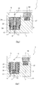
- Fig. 1, 2 . 5 and 6 a first embodiment of an electropneumatic solenoid valve according to the invention is shown, which is generally provided with the reference numeral 1.
- the electro-pneumatic solenoid valve 1 comprises a housing 3 with a lid 5 which is fixed to the housing 3.
- Two air ducts are introduced into the housing structure on a connection wall section 7 of the housing 3 opposite the cover 5, namely an air discharge duct 11 and an air supply duct 13.
- the three air channels 11, 13, 15 are pneumatically connected to an air chamber 17, which is bounded in part by an inner wall surface of the housing 3.
- the air space 17 is cylindrical and additionally bounded by a magnetic rim structure of an electromagnetic actuator 21, which will be explained later.
- a plate-shaped impact valve member 23 is movably mounted floating.
- the impact valve member 23 comprises a planar baffle plate 25 of magnetic, in particular soft magnetic, material, wherein the baffle plate 25 comprises two flat plate surfaces 27, 29, is arranged perpendicular to the axial direction of adjustment S, along which the electromagnetic actuator 21, the impact valve member 23.
- the air supply duct 13 extends coaxially to the axial adjustment direction S, wherein the course of the discharge channel 11 in the connection section 7 of the housing 3 also extends in the axial adjustment direction S but is offset radially to the air supply channel 13. As already indicated above, both air channels 11, 13 open into the air chamber 17.
- a recess is provided, in which a spherical closure element 31 made of a non-magnetic material, such as ceramic, used and attached, in particular pressed, is.
- the spherical closure element 31 protrudes in the axial direction on both plate surfaces 27, 29, on a side 27 at the radial height of the feed channel 13, facing on the other side 29 at the radial height of the mouth region of the vent channel 15 in a coil core 33 of the electromagnetic Adjusting device 21 is introduced.
- the semispherical or partially spherical, protruding closure elements projecting from the flat baffle plate 25 are dimensioned such that they can engage in the corresponding stop position in the mouth region of the respective air channel 13, 15 substantially airtight, on the one hand the venting of the electro-pneumatic solenoid valve.
- the electromagnetic actuator 21 comprises a coil 37 which surrounds the spool core 33 in the circumferential direction.
- the coil 37 is connected to an electrical actuation source in particular via a positioner or control device and receives electrical control signals to magnetically actuate the magnetizable baffle plate 25 of the baffle valve member 23.
- Fig. 1 the state of attraction is shown in which the coil 37 is activated and can be reached via the magnetic closure on the impingement-valve member-side section of the magnetized coil core 33 and the coil jacket 39 surrounding the coil 37 on the outside.
- Fig. 2 the inactive spool 37 is shown and the impact valve member 23 is pressed against the mouth edge of the feed channel 13 due to the spring 41 formed as a constraining means in order to close it airtight ( Fig. 2 ).
- the baffle valve member 23 is floating within the air chamber 17, ie the single forces acting on the baffle valve member 23 are optionally the electromagnetic forces of the actuator, if activated, and the constant compression spring force of the spring 41 and the weight of the baffle valve member itself ( depending on the orientation of the solenoid valve with respect to the direction of gravity).
- An additional guide to the axial Relocating the impact valve member 23 in the axial direction of adjustment S is not necessary.
- the impact valve member when it is stationary in the respective end position (closure of the supply line of the feed channel 13 / closure of the vent channel 15), because the spherical closure element 33 fits self-centering in the mouth of the respective air channel.
- no further guidance is provided on the way from the one end position to the other air channel closing position, in order to set the impact valve member 23 axially within the air chamber.
- a magnetic field is electromagnetically constructed, which is to actuate the impact valve member 23 depending on the determination of the electromagnetic actuator.
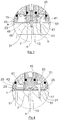
- the solenoid valve in particular the axial displaceability of the impact valve member, are easily checked by a function check mechanism, which is in particular formed by an additional permanent magnet 55, which can be brought from a stowed position to a test position, in particular pivotable.
- the permanent magnet 55 serves to set the magnetizable components of the electromagnetic device in a magnetic field and to check whether then the impact valve member 23 is placed axially.
- An energization of the electromagnetic actuator 21 is not necessary in the function check due to the additional use of the permanent magnet 55.
- the stowage state of the permanent magnet 55 is in Fig. 1 shown.
- the active test state is not shown in detail in the figures.
- the permanent magnet 55 is located in the axial direction adjacent to (above) the electromagnetic actuator 21.
- this is a soft magnetic fixing member 57 opposite, whereby the permanent magnet 55 is held under the influence of its magnetic force in position.
- the holding forces In order to pivot the permanent magnet 55 in the active position, which is not shown in detail, the holding forces must be overcome.
- the permanent magnet 55 In the test position in which the permanent magnet 55 is "activated or activated", the permanent magnet 55 is diametrically on the opposite side of the baffle plate 25 and actuates them magnetically contactless. This way you can visually check whether the baffle plate 25, depending on the position of the permanent magnet 55, the respective air channel 13, 15 closes.
- the stopper plate sections 49, 53 are not necessarily occurring during normal operation stops, since the floating bearing due to the prevailing forces well balanced is, so that a stop with respect to the design of the closing element 31 and the respective mouth areas of the air ducts 13, 15 is adjusted, so that a stop is not considered. Only with exceptional load, such as impact load, may be a stop with regard to the said plate sections.
- This circumferential gap exists when the plate 25 of the baffle valve member 23 is aligned perpendicular to the actuating direction axis S.
- Fig. 5 represents the state of the airtight seal of the vent passage 15, the circumferential axial distance a, which is constant in particular in the entire circumferential direction, slightly smaller than the axial distance b of the baffle plate 25 with respect to the end face 45 of the coil 33.
- the axial gap a ⁇ (smaller than or equal to) half of the axial distance b.
- the axial distance a should not be greater than 0.1 mm, 0.2 mm, 0.3 mm or 1 mm.
- the spring 41 takes over the operation of the impact valve member 23 and presses the latter against the inside of the connection wall portion 7 of the housing 3, whereby the facing spherical closure element 31 airtightly engages against the mouth of the feed channel 13. In this way, the air supply through the air passage 13 is prevented, and the discharge channel 11 is pneumatically connected to the vent passage 15, whereby the electro-pneumatic solenoid valve 1 is vented. It can be seen that the position of the baffle plate 25 of the baffle valve member 23 due to the engagement of the spherical closure member 31 in the mouth of the air supply duct 13 in combination with the compressive forces of the positive spring 41 ensures a stable airtight end position of the baffle valve plate.
- a guide pin 51 is fixed to the connection portion 7 and projects into the air chamber 17.
- This guide pin 51 is primarily not used to guide the baffle valve member 23 during normal operation of the reciprocating the baffle valve member 23 in the axial direction of adjustment S. Rather, should be provided with the insertion of the pin, an axial guide 51 to the effect that the radial position of the baffle valve member is secured in jerky overload movements on the solenoid valve, for example, during transport or assembly to avoid misalignment of the baffle valve member 23.
- these guide pins 51 can be omitted, even if the radial distance r between the annular outer edge of the plate 25 of the impact valve member 23 and the opposite cylindrical inner wall side of the housing 3 of the air chamber 17 allows only a slight radial movement.
- pin in addition to the individual in 3 and 4 shown pin can also be provided several pins without they perform a leadership function.
- On the pins can preferably be dispensed with.
- the radial distance or gap r is less than 2 mm, preferably none than 1 mm, 0.5 mm or 0.2 mm.
- the baffle valve member 23 shown in the figures is preferably made of a soft magnetic material, such as metal, preferably ferrite, to receive attractive forces by the electromagnetic actuator.
- a soft magnetic material such as metal, preferably ferrite
- the magnetic impingement valve member may be provided with a coating of non-magnetic material, such as Teflon, which avoids sticking.
- the baffle plate 25 may also be realized by a non-metallic material, such as plastic, which is provided with metallic particles for absorbing attractive forces. With such a plastic impact valve member design, a non-magnetic coating may be dispensed with.
- the air chamber is more or less a cylindrical gap with an axial depth of slightly greater, preferably three or four times, less than five times the axial thickness of the plate 25 of the impingement valve member 23 executed. In this way, a tilting of the floating-mounted impact valve member 23 is hindered in particular during assembly and transport.
- the radial stops such as the inside of the housing 3, and the axial stops, as in the coil shell 43 and the coil core 33, in particular their end faces and the opposite radially extending inner wall surfaces, do not serve to guide the impact valve member.
- solenoid valve 1 can be used in particular for use in positioners and in combination with pneumatic drives which are simple and double-acting.
Applications Claiming Priority (1)
| Application Number | Priority Date | Filing Date | Title |
|---|---|---|---|
| DE102016106410.6A DE102016106410A1 (de) | 2016-04-07 | 2016-04-07 | Elektropneumatisches Magnetventil, Prallventilglied für ein elektropneumatisches Magnetventil |
Publications (2)
| Publication Number | Publication Date |
|---|---|
| EP3228908A1 true EP3228908A1 (fr) | 2017-10-11 |
| EP3228908B1 EP3228908B1 (fr) | 2020-06-24 |
Family
ID=58536762
Family Applications (1)
| Application Number | Title | Priority Date | Filing Date |
|---|---|---|---|
| EP17165153.2A Active EP3228908B1 (fr) | 2016-04-07 | 2017-04-06 | Électrovanne électropneumatique, organe de valve à miroir pour une électrovanne électropneumatique |
Country Status (4)
| Country | Link |
|---|---|
| US (1) | US10724651B2 (fr) |
| EP (1) | EP3228908B1 (fr) |
| CN (1) | CN207261672U (fr) |
| DE (1) | DE102016106410A1 (fr) |
Families Citing this family (4)
| Publication number | Priority date | Publication date | Assignee | Title |
|---|---|---|---|---|
| DE102017106297B4 (de) | 2017-03-23 | 2023-01-19 | Samson Aktiengesellschaft | Elektromagnetische Prallventilanordnung |
| DE102018123166B3 (de) * | 2018-09-20 | 2020-03-12 | Samson Aktiengesellschaft | Elektrisch-pneumatischer Umformer |
| DE202023102911U1 (de) | 2023-05-25 | 2023-06-06 | Samson Aktiengesellschaft | Magnetventil mit schwenkbarer Ventilplatte |
| DE202023102904U1 (de) | 2023-05-25 | 2023-06-09 | Samson Aktiengesellschaft | Magnetventil mit Druckentlastung und System für ein pneumatisch betriebenes Feldgerät |
Citations (5)
| Publication number | Priority date | Publication date | Assignee | Title |
|---|---|---|---|---|
| DE9017107U1 (fr) * | 1990-12-19 | 1992-04-16 | Robert Bosch Gmbh, 7000 Stuttgart, De | |
| DE19636207C2 (de) | 1996-09-06 | 2000-08-03 | Samson Ag | Elektrisch-fluidischer Wandler |
| US20020135451A1 (en) * | 2001-03-20 | 2002-09-26 | Dieter Frank | Method for manufacturing a magnet armature |
| US20040261850A1 (en) * | 2003-06-26 | 2004-12-30 | Maula Jarmo Ilmari | Diaphragm valve for high-temperature precursor supply in atomic layer deposition |
| US20050115618A1 (en) * | 2003-12-01 | 2005-06-02 | Kumar Viraraghavan S. | Co-axial solenoid actuator |
Family Cites Families (13)
| Publication number | Priority date | Publication date | Assignee | Title |
|---|---|---|---|---|
| US3921670A (en) * | 1974-07-01 | 1975-11-25 | Clippard Instr Lab Inc | Magnetically operated valve with spider armature |
| US4196751A (en) * | 1976-01-15 | 1980-04-08 | Johnson Controls, Inc. | Electric to fluid signal valve unit |
| CH645445A5 (de) * | 1979-03-17 | 1984-09-28 | Festo Maschf Stoll G | Magnetventil. |
| US4705073A (en) * | 1986-04-23 | 1987-11-10 | Advanced Medical Devices, Inc. | Molded plastic gate valve and sealing means therefor |
| DE4243179C2 (de) * | 1992-12-19 | 2001-08-16 | Bosch Gmbh Robert | Elektromagnetventil |
| DE4428385B4 (de) * | 1994-08-11 | 2005-03-17 | Robert Bosch Gmbh | Ventilkörper |
| DE19901090A1 (de) * | 1999-01-14 | 2000-07-20 | Bosch Gmbh Robert | Ventil zum dosierten Einleiten von verflüchtigtem Brennstoff |
| DE10064349C1 (de) * | 2000-12-21 | 2002-05-08 | Danfoss As | Magnetventil |
| KR20060084360A (ko) | 2003-06-26 | 2006-07-24 | 플레이너 시스템스 인코포레이티드 | 원자 층 증착을 위한 다이아프램 밸브 |
| DE10340941A1 (de) * | 2003-09-05 | 2005-03-31 | Robert Bosch Gmbh | Magnetventil |
| DE102009038103A1 (de) * | 2009-08-19 | 2011-02-24 | Moeller Gmbh | Elektromagnetanordnung |
| US8690118B2 (en) * | 2010-01-08 | 2014-04-08 | Caterpillar Inc. | Solenoid actuated device and methods |
| US8684036B1 (en) * | 2013-03-07 | 2014-04-01 | Yozo Satoda | Cryogenic valve |
-
2016
- 2016-04-07 DE DE102016106410.6A patent/DE102016106410A1/de active Pending
-
2017
- 2017-04-06 EP EP17165153.2A patent/EP3228908B1/fr active Active
- 2017-04-07 US US15/482,127 patent/US10724651B2/en active Active
- 2017-04-07 CN CN201720358194.1U patent/CN207261672U/zh active Active
Patent Citations (5)
| Publication number | Priority date | Publication date | Assignee | Title |
|---|---|---|---|---|
| DE9017107U1 (fr) * | 1990-12-19 | 1992-04-16 | Robert Bosch Gmbh, 7000 Stuttgart, De | |
| DE19636207C2 (de) | 1996-09-06 | 2000-08-03 | Samson Ag | Elektrisch-fluidischer Wandler |
| US20020135451A1 (en) * | 2001-03-20 | 2002-09-26 | Dieter Frank | Method for manufacturing a magnet armature |
| US20040261850A1 (en) * | 2003-06-26 | 2004-12-30 | Maula Jarmo Ilmari | Diaphragm valve for high-temperature precursor supply in atomic layer deposition |
| US20050115618A1 (en) * | 2003-12-01 | 2005-06-02 | Kumar Viraraghavan S. | Co-axial solenoid actuator |
Also Published As
| Publication number | Publication date |
|---|---|
| EP3228908B1 (fr) | 2020-06-24 |
| CN207261672U (zh) | 2018-04-20 |
| US10724651B2 (en) | 2020-07-28 |
| DE102016106410A1 (de) | 2017-10-12 |
| US20170292627A1 (en) | 2017-10-12 |
Similar Documents
| Publication | Publication Date | Title |
|---|---|---|
| EP3228908A1 (fr) | Électrovanne électropneumatique, organe de valve à miroir pour une électrovanne électropneumatique | |
| DE102005035798B4 (de) | Elektromagnetventil | |
| DE60108282T2 (de) | Elektromagnetventil | |
| EP3215771B1 (fr) | Soupape proportionnelle, ensemble compresseur de climatisation et procédé de fonctionnement | |
| DE102014115251A1 (de) | Elektromagnetventil | |
| EP3359415A1 (fr) | Répartiteur de pression pour véhicule automobile | |
| EP2405166B1 (fr) | Soupape électromagnétique | |
| DE10017030B4 (de) | Magnetventil | |
| DE2755239A1 (de) | Pneumatischer antrieb fuer schalt- und stellglieder | |
| WO2015007425A1 (fr) | Dispositif formant soupape électromagnétique et porte-bobine | |
| EP1217273A2 (fr) | Soupape électromagnétique | |
| EP2080942B1 (fr) | Dispositif de ventilation doté d'un dispositif de fixation à aimant permanent | |
| EP3234423B1 (fr) | Soupape pour commander l'écoulement d'un fluide | |
| EP3008366A1 (fr) | Électrovanne de réglage de débit d'un fluide sous pression | |
| EP3379120B1 (fr) | Dispositif de soupape de détente électromagnétique | |
| DE2540751C2 (fr) | ||
| DE102004037269B3 (de) | Elektropneumatisches Ventil mit pneumatisch betätigtem Steuerkolben | |
| EP3228913A1 (fr) | Électrovanne électropneumatique | |
| WO1992015809A1 (fr) | Soupape, de preference soupape a vide | |
| DE102014016701A1 (de) | Steuerbares Rückschlagventil | |
| DE10031873B4 (de) | Hydraulisches Ventil | |
| DE19636207C2 (de) | Elektrisch-fluidischer Wandler | |
| DE2248428A1 (de) | Elektropneumatische regelvorrichtung | |
| EP1528305B1 (fr) | Soupape électromagnétique | |
| DE202023102904U1 (de) | Magnetventil mit Druckentlastung und System für ein pneumatisch betriebenes Feldgerät |
Legal Events
| Date | Code | Title | Description |
|---|---|---|---|
| PUAI | Public reference made under article 153(3) epc to a published international application that has entered the european phase |
Free format text: ORIGINAL CODE: 0009012 |
|
| STAA | Information on the status of an ep patent application or granted ep patent |
Free format text: STATUS: THE APPLICATION HAS BEEN PUBLISHED |
|
| AK | Designated contracting states |
Kind code of ref document: A1 Designated state(s): AL AT BE BG CH CY CZ DE DK EE ES FI FR GB GR HR HU IE IS IT LI LT LU LV MC MK MT NL NO PL PT RO RS SE SI SK SM TR |
|
| AX | Request for extension of the european patent |
Extension state: BA ME |
|
| STAA | Information on the status of an ep patent application or granted ep patent |
Free format text: STATUS: REQUEST FOR EXAMINATION WAS MADE |
|
| 17P | Request for examination filed |
Effective date: 20180405 |
|
| RBV | Designated contracting states (corrected) |
Designated state(s): AL AT BE BG CH CY CZ DE DK EE ES FI FR GB GR HR HU IE IS IT LI LT LU LV MC MK MT NL NO PL PT RO RS SE SI SK SM TR |
|
| STAA | Information on the status of an ep patent application or granted ep patent |
Free format text: STATUS: EXAMINATION IS IN PROGRESS |
|
| 17Q | First examination report despatched |
Effective date: 20180710 |
|
| GRAP | Despatch of communication of intention to grant a patent |
Free format text: ORIGINAL CODE: EPIDOSNIGR1 |
|
| STAA | Information on the status of an ep patent application or granted ep patent |
Free format text: STATUS: GRANT OF PATENT IS INTENDED |
|
| INTG | Intention to grant announced |
Effective date: 20200203 |
|
| GRAS | Grant fee paid |
Free format text: ORIGINAL CODE: EPIDOSNIGR3 |
|
| GRAA | (expected) grant |
Free format text: ORIGINAL CODE: 0009210 |
|
| STAA | Information on the status of an ep patent application or granted ep patent |
Free format text: STATUS: THE PATENT HAS BEEN GRANTED |
|
| AK | Designated contracting states |
Kind code of ref document: B1 Designated state(s): AL AT BE BG CH CY CZ DE DK EE ES FI FR GB GR HR HU IE IS IT LI LT LU LV MC MK MT NL NO PL PT RO RS SE SI SK SM TR |
|
| REG | Reference to a national code |
Ref country code: GB Ref legal event code: FG4D Free format text: NOT ENGLISH |
|
| REG | Reference to a national code |
Ref country code: CH Ref legal event code: EP |
|
| REG | Reference to a national code |
Ref country code: AT Ref legal event code: REF Ref document number: 1284220 Country of ref document: AT Kind code of ref document: T Effective date: 20200715 |
|
| REG | Reference to a national code |
Ref country code: DE Ref legal event code: R096 Ref document number: 502017005816 Country of ref document: DE |
|
| REG | Reference to a national code |
Ref country code: IE Ref legal event code: FG4D Free format text: LANGUAGE OF EP DOCUMENT: GERMAN |
|
| PG25 | Lapsed in a contracting state [announced via postgrant information from national office to epo] |
Ref country code: SE Free format text: LAPSE BECAUSE OF FAILURE TO SUBMIT A TRANSLATION OF THE DESCRIPTION OR TO PAY THE FEE WITHIN THE PRESCRIBED TIME-LIMIT Effective date: 20200624 Ref country code: LT Free format text: LAPSE BECAUSE OF FAILURE TO SUBMIT A TRANSLATION OF THE DESCRIPTION OR TO PAY THE FEE WITHIN THE PRESCRIBED TIME-LIMIT Effective date: 20200624 Ref country code: GR Free format text: LAPSE BECAUSE OF FAILURE TO SUBMIT A TRANSLATION OF THE DESCRIPTION OR TO PAY THE FEE WITHIN THE PRESCRIBED TIME-LIMIT Effective date: 20200925 Ref country code: NO Free format text: LAPSE BECAUSE OF FAILURE TO SUBMIT A TRANSLATION OF THE DESCRIPTION OR TO PAY THE FEE WITHIN THE PRESCRIBED TIME-LIMIT Effective date: 20200924 Ref country code: FI Free format text: LAPSE BECAUSE OF FAILURE TO SUBMIT A TRANSLATION OF THE DESCRIPTION OR TO PAY THE FEE WITHIN THE PRESCRIBED TIME-LIMIT Effective date: 20200624 |
|
| REG | Reference to a national code |
Ref country code: LT Ref legal event code: MG4D |
|
| PG25 | Lapsed in a contracting state [announced via postgrant information from national office to epo] |
Ref country code: LV Free format text: LAPSE BECAUSE OF FAILURE TO SUBMIT A TRANSLATION OF THE DESCRIPTION OR TO PAY THE FEE WITHIN THE PRESCRIBED TIME-LIMIT Effective date: 20200624 Ref country code: HR Free format text: LAPSE BECAUSE OF FAILURE TO SUBMIT A TRANSLATION OF THE DESCRIPTION OR TO PAY THE FEE WITHIN THE PRESCRIBED TIME-LIMIT Effective date: 20200624 Ref country code: BG Free format text: LAPSE BECAUSE OF FAILURE TO SUBMIT A TRANSLATION OF THE DESCRIPTION OR TO PAY THE FEE WITHIN THE PRESCRIBED TIME-LIMIT Effective date: 20200924 Ref country code: RS Free format text: LAPSE BECAUSE OF FAILURE TO SUBMIT A TRANSLATION OF THE DESCRIPTION OR TO PAY THE FEE WITHIN THE PRESCRIBED TIME-LIMIT Effective date: 20200624 |
|
| REG | Reference to a national code |
Ref country code: NL Ref legal event code: MP Effective date: 20200624 |
|
| PG25 | Lapsed in a contracting state [announced via postgrant information from national office to epo] |
Ref country code: AL Free format text: LAPSE BECAUSE OF FAILURE TO SUBMIT A TRANSLATION OF THE DESCRIPTION OR TO PAY THE FEE WITHIN THE PRESCRIBED TIME-LIMIT Effective date: 20200624 Ref country code: NL Free format text: LAPSE BECAUSE OF FAILURE TO SUBMIT A TRANSLATION OF THE DESCRIPTION OR TO PAY THE FEE WITHIN THE PRESCRIBED TIME-LIMIT Effective date: 20200624 |
|
| PG25 | Lapsed in a contracting state [announced via postgrant information from national office to epo] |
Ref country code: IT Free format text: LAPSE BECAUSE OF FAILURE TO SUBMIT A TRANSLATION OF THE DESCRIPTION OR TO PAY THE FEE WITHIN THE PRESCRIBED TIME-LIMIT Effective date: 20200624 Ref country code: RO Free format text: LAPSE BECAUSE OF FAILURE TO SUBMIT A TRANSLATION OF THE DESCRIPTION OR TO PAY THE FEE WITHIN THE PRESCRIBED TIME-LIMIT Effective date: 20200624 Ref country code: CZ Free format text: LAPSE BECAUSE OF FAILURE TO SUBMIT A TRANSLATION OF THE DESCRIPTION OR TO PAY THE FEE WITHIN THE PRESCRIBED TIME-LIMIT Effective date: 20200624 Ref country code: PT Free format text: LAPSE BECAUSE OF FAILURE TO SUBMIT A TRANSLATION OF THE DESCRIPTION OR TO PAY THE FEE WITHIN THE PRESCRIBED TIME-LIMIT Effective date: 20201026 Ref country code: ES Free format text: LAPSE BECAUSE OF FAILURE TO SUBMIT A TRANSLATION OF THE DESCRIPTION OR TO PAY THE FEE WITHIN THE PRESCRIBED TIME-LIMIT Effective date: 20200624 Ref country code: EE Free format text: LAPSE BECAUSE OF FAILURE TO SUBMIT A TRANSLATION OF THE DESCRIPTION OR TO PAY THE FEE WITHIN THE PRESCRIBED TIME-LIMIT Effective date: 20200624 Ref country code: SM Free format text: LAPSE BECAUSE OF FAILURE TO SUBMIT A TRANSLATION OF THE DESCRIPTION OR TO PAY THE FEE WITHIN THE PRESCRIBED TIME-LIMIT Effective date: 20200624 |
|
| PG25 | Lapsed in a contracting state [announced via postgrant information from national office to epo] |
Ref country code: SK Free format text: LAPSE BECAUSE OF FAILURE TO SUBMIT A TRANSLATION OF THE DESCRIPTION OR TO PAY THE FEE WITHIN THE PRESCRIBED TIME-LIMIT Effective date: 20200624 Ref country code: PL Free format text: LAPSE BECAUSE OF FAILURE TO SUBMIT A TRANSLATION OF THE DESCRIPTION OR TO PAY THE FEE WITHIN THE PRESCRIBED TIME-LIMIT Effective date: 20200624 Ref country code: IS Free format text: LAPSE BECAUSE OF FAILURE TO SUBMIT A TRANSLATION OF THE DESCRIPTION OR TO PAY THE FEE WITHIN THE PRESCRIBED TIME-LIMIT Effective date: 20201024 |
|
| REG | Reference to a national code |
Ref country code: DE Ref legal event code: R097 Ref document number: 502017005816 Country of ref document: DE |
|
| PG25 | Lapsed in a contracting state [announced via postgrant information from national office to epo] |
Ref country code: DK Free format text: LAPSE BECAUSE OF FAILURE TO SUBMIT A TRANSLATION OF THE DESCRIPTION OR TO PAY THE FEE WITHIN THE PRESCRIBED TIME-LIMIT Effective date: 20200624 |
|
| PLBE | No opposition filed within time limit |
Free format text: ORIGINAL CODE: 0009261 |
|
| STAA | Information on the status of an ep patent application or granted ep patent |
Free format text: STATUS: NO OPPOSITION FILED WITHIN TIME LIMIT |
|
| 26N | No opposition filed |
Effective date: 20210325 |
|
| PG25 | Lapsed in a contracting state [announced via postgrant information from national office to epo] |
Ref country code: SI Free format text: LAPSE BECAUSE OF FAILURE TO SUBMIT A TRANSLATION OF THE DESCRIPTION OR TO PAY THE FEE WITHIN THE PRESCRIBED TIME-LIMIT Effective date: 20200624 |
|
| PG25 | Lapsed in a contracting state [announced via postgrant information from national office to epo] |
Ref country code: MC Free format text: LAPSE BECAUSE OF FAILURE TO SUBMIT A TRANSLATION OF THE DESCRIPTION OR TO PAY THE FEE WITHIN THE PRESCRIBED TIME-LIMIT Effective date: 20200624 |
|
| PG25 | Lapsed in a contracting state [announced via postgrant information from national office to epo] |
Ref country code: LU Free format text: LAPSE BECAUSE OF NON-PAYMENT OF DUE FEES Effective date: 20210406 |
|
| REG | Reference to a national code |
Ref country code: BE Ref legal event code: MM Effective date: 20210430 |
|
| PG25 | Lapsed in a contracting state [announced via postgrant information from national office to epo] |
Ref country code: CH Free format text: LAPSE BECAUSE OF NON-PAYMENT OF DUE FEES Effective date: 20210430 Ref country code: LI Free format text: LAPSE BECAUSE OF NON-PAYMENT OF DUE FEES Effective date: 20210430 |
|
| PG25 | Lapsed in a contracting state [announced via postgrant information from national office to epo] |
Ref country code: IE Free format text: LAPSE BECAUSE OF NON-PAYMENT OF DUE FEES Effective date: 20210406 |
|
| PG25 | Lapsed in a contracting state [announced via postgrant information from national office to epo] |
Ref country code: IS Free format text: LAPSE BECAUSE OF FAILURE TO SUBMIT A TRANSLATION OF THE DESCRIPTION OR TO PAY THE FEE WITHIN THE PRESCRIBED TIME-LIMIT Effective date: 20201024 |
|
| PG25 | Lapsed in a contracting state [announced via postgrant information from national office to epo] |
Ref country code: BE Free format text: LAPSE BECAUSE OF NON-PAYMENT OF DUE FEES Effective date: 20210430 |
|
| REG | Reference to a national code |
Ref country code: DE Ref legal event code: R082 Ref document number: 502017005816 Country of ref document: DE Representative=s name: SKM-IP SCHMID KRAUSS KUTTENKEULER MALESCHA SCH, DE |
|
| PG25 | Lapsed in a contracting state [announced via postgrant information from national office to epo] |
Ref country code: HU Free format text: LAPSE BECAUSE OF FAILURE TO SUBMIT A TRANSLATION OF THE DESCRIPTION OR TO PAY THE FEE WITHIN THE PRESCRIBED TIME-LIMIT; INVALID AB INITIO Effective date: 20170406 |
|
| REG | Reference to a national code |
Ref country code: AT Ref legal event code: MM01 Ref document number: 1284220 Country of ref document: AT Kind code of ref document: T Effective date: 20220406 |
|
| PG25 | Lapsed in a contracting state [announced via postgrant information from national office to epo] |
Ref country code: CY Free format text: LAPSE BECAUSE OF FAILURE TO SUBMIT A TRANSLATION OF THE DESCRIPTION OR TO PAY THE FEE WITHIN THE PRESCRIBED TIME-LIMIT Effective date: 20200624 |
|
| PG25 | Lapsed in a contracting state [announced via postgrant information from national office to epo] |
Ref country code: AT Free format text: LAPSE BECAUSE OF NON-PAYMENT OF DUE FEES Effective date: 20220406 |
|
| PGFP | Annual fee paid to national office [announced via postgrant information from national office to epo] |
Ref country code: FR Payment date: 20230424 Year of fee payment: 7 Ref country code: DE Payment date: 20230420 Year of fee payment: 7 |
|
| P01 | Opt-out of the competence of the unified patent court (upc) registered |
Effective date: 20230713 |
|
| PGFP | Annual fee paid to national office [announced via postgrant information from national office to epo] |
Ref country code: GB Payment date: 20230419 Year of fee payment: 7 |