EP3228908A1 - Electropneumatic solenoid valve, impact valve body for an electropneumatic solenoid valve - Google Patents
Electropneumatic solenoid valve, impact valve body for an electropneumatic solenoid valve Download PDFInfo
- Publication number
- EP3228908A1 EP3228908A1 EP17165153.2A EP17165153A EP3228908A1 EP 3228908 A1 EP3228908 A1 EP 3228908A1 EP 17165153 A EP17165153 A EP 17165153A EP 3228908 A1 EP3228908 A1 EP 3228908A1
- Authority
- EP
- European Patent Office
- Prior art keywords
- valve member
- air
- solenoid valve
- baffle
- impact
- Prior art date
- Legal status (The legal status is an assumption and is not a legal conclusion. Google has not performed a legal analysis and makes no representation as to the accuracy of the status listed.)
- Granted
Links
Images

Classifications
-
- F—MECHANICAL ENGINEERING; LIGHTING; HEATING; WEAPONS; BLASTING
- F16—ENGINEERING ELEMENTS AND UNITS; GENERAL MEASURES FOR PRODUCING AND MAINTAINING EFFECTIVE FUNCTIONING OF MACHINES OR INSTALLATIONS; THERMAL INSULATION IN GENERAL
- F16K—VALVES; TAPS; COCKS; ACTUATING-FLOATS; DEVICES FOR VENTING OR AERATING
- F16K31/00—Actuating devices; Operating means; Releasing devices
- F16K31/02—Actuating devices; Operating means; Releasing devices electric; magnetic
- F16K31/06—Actuating devices; Operating means; Releasing devices electric; magnetic using a magnet, e.g. diaphragm valves, cutting off by means of a liquid
- F16K31/08—Actuating devices; Operating means; Releasing devices electric; magnetic using a magnet, e.g. diaphragm valves, cutting off by means of a liquid using a permanent magnet
- F16K31/086—Actuating devices; Operating means; Releasing devices electric; magnetic using a magnet, e.g. diaphragm valves, cutting off by means of a liquid using a permanent magnet the magnet being movable and actuating a second magnet connected to the closing element
-
- F—MECHANICAL ENGINEERING; LIGHTING; HEATING; WEAPONS; BLASTING
- F16—ENGINEERING ELEMENTS AND UNITS; GENERAL MEASURES FOR PRODUCING AND MAINTAINING EFFECTIVE FUNCTIONING OF MACHINES OR INSTALLATIONS; THERMAL INSULATION IN GENERAL
- F16K—VALVES; TAPS; COCKS; ACTUATING-FLOATS; DEVICES FOR VENTING OR AERATING
- F16K31/00—Actuating devices; Operating means; Releasing devices
- F16K31/12—Actuating devices; Operating means; Releasing devices actuated by fluid
- F16K31/42—Actuating devices; Operating means; Releasing devices actuated by fluid by means of electrically-actuated members in the supply or discharge conduits of the fluid motor
- F16K31/423—Actuating devices; Operating means; Releasing devices actuated by fluid by means of electrically-actuated members in the supply or discharge conduits of the fluid motor the actuated members consisting of multiple way valves
-
- F—MECHANICAL ENGINEERING; LIGHTING; HEATING; WEAPONS; BLASTING
- F15—FLUID-PRESSURE ACTUATORS; HYDRAULICS OR PNEUMATICS IN GENERAL
- F15B—SYSTEMS ACTING BY MEANS OF FLUIDS IN GENERAL; FLUID-PRESSURE ACTUATORS, e.g. SERVOMOTORS; DETAILS OF FLUID-PRESSURE SYSTEMS, NOT OTHERWISE PROVIDED FOR
- F15B13/00—Details of servomotor systems ; Valves for servomotor systems
- F15B13/02—Fluid distribution or supply devices characterised by their adaptation to the control of servomotors
- F15B13/04—Fluid distribution or supply devices characterised by their adaptation to the control of servomotors for use with a single servomotor
- F15B13/042—Fluid distribution or supply devices characterised by their adaptation to the control of servomotors for use with a single servomotor operated by fluid pressure
- F15B13/043—Fluid distribution or supply devices characterised by their adaptation to the control of servomotors for use with a single servomotor operated by fluid pressure with electrically-controlled pilot valves
- F15B13/0438—Fluid distribution or supply devices characterised by their adaptation to the control of servomotors for use with a single servomotor operated by fluid pressure with electrically-controlled pilot valves the pilot valves being of the nozzle-flapper type
-
- F—MECHANICAL ENGINEERING; LIGHTING; HEATING; WEAPONS; BLASTING
- F16—ENGINEERING ELEMENTS AND UNITS; GENERAL MEASURES FOR PRODUCING AND MAINTAINING EFFECTIVE FUNCTIONING OF MACHINES OR INSTALLATIONS; THERMAL INSULATION IN GENERAL
- F16K—VALVES; TAPS; COCKS; ACTUATING-FLOATS; DEVICES FOR VENTING OR AERATING
- F16K31/00—Actuating devices; Operating means; Releasing devices
- F16K31/02—Actuating devices; Operating means; Releasing devices electric; magnetic
- F16K31/06—Actuating devices; Operating means; Releasing devices electric; magnetic using a magnet, e.g. diaphragm valves, cutting off by means of a liquid
- F16K31/0603—Multiple-way valves
- F16K31/0606—Multiple-way valves fluid passing through the solenoid coil
-
- F—MECHANICAL ENGINEERING; LIGHTING; HEATING; WEAPONS; BLASTING
- F16—ENGINEERING ELEMENTS AND UNITS; GENERAL MEASURES FOR PRODUCING AND MAINTAINING EFFECTIVE FUNCTIONING OF MACHINES OR INSTALLATIONS; THERMAL INSULATION IN GENERAL
- F16K—VALVES; TAPS; COCKS; ACTUATING-FLOATS; DEVICES FOR VENTING OR AERATING
- F16K31/00—Actuating devices; Operating means; Releasing devices
- F16K31/02—Actuating devices; Operating means; Releasing devices electric; magnetic
- F16K31/06—Actuating devices; Operating means; Releasing devices electric; magnetic using a magnet, e.g. diaphragm valves, cutting off by means of a liquid
- F16K31/0603—Multiple-way valves
- F16K31/0624—Lift valves
- F16K31/0627—Lift valves with movable valve member positioned between seats
- F16K31/0631—Lift valves with movable valve member positioned between seats with ball shaped valve members
-
- F—MECHANICAL ENGINEERING; LIGHTING; HEATING; WEAPONS; BLASTING
- F15—FLUID-PRESSURE ACTUATORS; HYDRAULICS OR PNEUMATICS IN GENERAL
- F15B—SYSTEMS ACTING BY MEANS OF FLUIDS IN GENERAL; FLUID-PRESSURE ACTUATORS, e.g. SERVOMOTORS; DETAILS OF FLUID-PRESSURE SYSTEMS, NOT OTHERWISE PROVIDED FOR
- F15B13/00—Details of servomotor systems ; Valves for servomotor systems
- F15B13/02—Fluid distribution or supply devices characterised by their adaptation to the control of servomotors
- F15B13/04—Fluid distribution or supply devices characterised by their adaptation to the control of servomotors for use with a single servomotor
- F15B13/0401—Valve members; Fluid interconnections therefor
- F15B13/0405—Valve members; Fluid interconnections therefor for seat valves, i.e. poppet valves
Definitions
- the invention relates to an electropneumatic solenoid valve for a pneumatically operated field device, in particular actuating device, such as a positioner, a process plant, such as a chemical plant, a petrochemical plant, a food processing plant, such as a brewery, a nuclear power plant or the like.
- actuating device such as a positioner, a process plant, such as a chemical plant, a petrochemical plant, a food processing plant, such as a brewery, a nuclear power plant or the like.
- the generic, electro-pneumatic solenoid valve has a housing structure in which usually an air supply duct, for connection to an air pressure source, an air discharge and a vent channel is formed.
- An impact valve member such as a baffle plate, is movably supported within an air chamber.
- An electromagnetic actuating device displaces the impact valve member in particular between two operating positions, in each of which one of the air ducts is closed.
- the baffle valve member is usually displaced in an axial direction of adjustment.
- the solenoid valve has a positive means, such as a spring, which forces the baffle valve member in the axial direction of adjustment into a closed position for closing one of the air ducts.
- the baffle valve member has a magnetic baffle that is floatingly guided in the air chamber except by the coercive means.
- an electropneumatic solenoid valve for a pneumatically operated field device, in particular actuating device, a process engineering plant, such as a chemical plant, a petrochemical plant, a food processing plant, such as a brewery, a nuclear power plant or the like.
- the solenoid valve has an air supply duct, in particular for connection to an air pressure source, for example, of a constant 6 (six) bar. At the air supply duct and a regulated air signal can be connected for example by an electropneumatic positioner.
- the solenoid valve has a Lucasab Novemberal for connection to, for example, a pneumatic actuator, which may be single or double acting.
- the solenoid valve may additionally have a ventilation channel.
- the magnetic valve defines an air chamber into which the air ducts open.
- the air chamber is preferably limited except by the internal structure of the housing of the solenoid valve by structures to be magnetized (in particular their axial boundary surfaces), which is for example the coil core or the coil jacket.
- one of the air ducts, such as the venting channel, is formed in the coil core.
- the electro-pneumatic solenoid valve has an impact valve member, such as a magnetizable baffle plate, which defines in particular parallel, flat plate sides, and an electromagnetic actuator, the impact valve member for loading and / or venting the Beerab Industrieskanals in a shifted axial actuator.
- the electromagnetic setting device is preferably formed by a coil to be electrically supplied, which radially surrounds the coil core of metal and has to build a closed magnetic circuit a coil surrounding the coil radially, which components are shown for example in more detail in the figures.
- the solenoid valve has an additional, in particular mechanical, positive means, such as a compression spring, or a magnetic forced operation, which forces the impact valve member in the direction of adjustment into a closed position for closing one of the air channels.
- the electromagnetic control device, the impact valve member between two operating positions, in particular closed positions move, in the one hand the Air supply duct or Heilab technicallykanal and on the other hand, the vent passage through the impingement valve member is airtightly locked.
- the baffle valve member has a particular lying on the Stelliquessachse closure element which comes to close one of the air ducts in particular with a Begrenzungsmündungsrand the air channel in such a way that the baffle valve member is arranged in a circumferential axial distance, in particular constant circumferential ring spacing to the axially adjacent boundary inner wall of the air chamber and is held so that the impact valve member remains immovable even in radial shocks in the closed position.
- the baffle valve member in the closed position in particular is sealingly in contact exclusively with the boundary mouth edge in order to ensure a secure and airtight closing of the air duct. Another contact with the boundary inner wall is excluded due to the circumferential axial distance.
- the circumferential axial distance is set in particular when the impact valve member is aligned in a particular vertical position to the actuating direction axis.
- the impact valve member is dimensioned with respect to the mouth edge of the air duct to be closed such that an independent alignment of the baffle valve member is caused in its displacement into the closure position, in particular under the influence of the electromagnetic forces and / or the coercive agent.
- the air duct to be closed and its mouth edge in the air chamber boundary wall are designed as a valve seat bore.
- the impact valve member, the seat bore, in particular opposite seat bores, and a particular axial maximum stroke of the baffle valve member in the air chamber are dimensioned / designed such that the baffle valve member, in particular in the region of the seat bores, in particular by the boundary edge of the housing structure / a core structure of the electromagnetic actuator, is held and centered when operating / closing in particular independently center of the seat bore.
- the bore edges of the seat bore form the support structure against which the impact valve member strikes to be held in the radial direction.
- valve system In another dimensioning of the valve system, it may well be due to the floating mounting of the baffle valve member that the baffle valve member at an inclination with respect to the direction of the actuator axis, for example, by an exceptional operating situation, how a shock load on the solenoid valve may be associated with coming into axial contact with a boundary inner wall of the air chamber, but only in a small-area contact point, but which does not affect the airtight closure of the air duct according to the invention.
- the baffle plate can be dimensioned and structured with respect to the particular plane boundary inner wall of the air chamber, that adjusts an especially constant circumferential axial distance to the boundary inner wall, in particular when the plate-shaped baffle valve member is aligned in a desired vertical position to the directional axis of the electromagnetic actuator.
- the baffle plate is to be arranged in the air chamber such that a radial contact of the baffle plate on the boundary wall of the air chamber is excluded. Radial contact is preferably to be avoided insofar as increased friction associated with contact would negatively impact performance.
- the radial distance between the baffle plate and the boundary wall of the air chamber is preferably to be selected, in particular to be dimensioned such that no radial contact can take place during normal operation of the actuation.
- the magnetic baffle plate may be stored in such a floating manner in normal operation that it is in an open state exclusively with the coercive means in touching contact and that it is in a closed state exclusively on the one hand with the coercive means and on the other hand with a valve seat or the like in touching contact.
- the baffle valve member in particular the magnetic baffle plate, without any further guide means disposed within the air chamber, so that a contact of the baffle valve member with boundary wall portions of the air chamber is accompanied only in the centering of the baffle valve member. Further contacts of the impact valve member, in particular the baffle plate should be excluded.
- the omission of other guide means such as guide pins, means a significant reduction in the assembly effort, and it was surprisingly found that the functionality of the floating-mounted impact valve is not affected.
- the closure element is formed as a protrusion projecting in particular on both sides from the preferably planar impact valve member, which is in particular at least partially convex-spherical.
- the closure element is formed / arranged in the axial center of a particular circular baffle plate of the baffle valve member.
- the closure element is designed as a ball mounted separately in the baffle plate and / or formed from a non-magnetic material, such as ceramic.
- the separately mounted ball consists exclusively of the non-magnetic material. In this way, the magnetic flux is not directed in the direction of the closure element, but deflected by it, so that the magnetic flux is redirected because of the non-magnetic closure element material. A magnetic sticking of the ball because of the residual magnetism between the ball and seat is therefore prevented.
- the baffle valve member has a radially inner mecanical mecanical и diametrically opposite to the coil core of the electromagnetic actuator axially, and the mecanicanschlags Scheme radially outwardly surrounding felicitanschlags Kunststoff, the coil of the electromagnetic actuator radially outwardly surrounding the coil jacket of the electromagnetic actuator or a housing portion of the solenoid valve diametrically opposite.
- the outer fence area does not necessarily have to serve the function of striking, however, should the floating support of the baffle plate, for example, by a temporary inclination in the case of assembly or impact load from the usual displacement position and direction get, so are an exceptional outer or internal impact allows for short-term tilting with limited amplitude of tilt.
- one of the air ducts is formed in the spool core.
- the air channel in the spool core with which the closure region is intended to cooperate tightly sealing, it is advantageous to provide the non-magnetic material for the closure element.
- the baffle plate and the associated stop regions are designed, structured and / or dimensioned in such a way that in particular sealing Occupancy of the air channel in the bobbin by the closure element of the baffle valve member, the radially outer axial distance of the baffle valve member to the outer stop area is smaller than the inner axial distance of the baffle valve member to the mecanicanschlags Scheme.
- the radial inner axial distance is less than 0.5 mm, 0.3 mm or 0.1 mm in occupancy of the air channel in the bobbin by the closure element.
- the radially outer axial distance is dimensioned at least one-third, preferably by about half, smaller than the radially inner axial distance. In this way it is ensured that the Kippamplitude of the floating-mounted impact valve member is limited, in particular by the outer stop.
- another air duct coaxially with the air duct, in particular the vent duct, in the coil core, another air duct, such as the air supply duct or Heilab adoptedal introduced in a housing wall of the solenoid valve such that a rear side of the closure element, the front of the air duct in the spool core closes, closes with appropriate axial displacement of the baffle valve member under the influence of the coercive force the air duct in the solenoid valve housing wall, wherein in particular radially offset from the air duct in the solenoid valve housing wall, a further air duct, such as Heilab technologicalkanal or air supply duct is formed, in particular of the baffle valve member at no axial parking position is closed.
- the radially offset air channel can not be closed at any axial adjustment position of the impact valve member by the impact valve member.
- the air chamber is bounded radially by a substantially cylindrical chamber inner wall, which is at least partially formed by the solenoid valve housing.
- the air chamber may be bounded axially by a lateral housing wall, in which at least two air channels are introduced, and which is opposite to the magnetizable component of the electromagnetic actuator. It is this magnetic structure of the electromagnetic actuator that limits the air chamber on the opposite axial side.
- the circular baffle plate of the baffle valve member in particular constant baffle plate thickness can be axially movable and in particular floatingly mounted like a piston. In particular, exclusively by the force means the impact valve member is guided mechanically.
- the axial maximum amplitude of movement of the baffle valve member in the axial direction of adjustment is at most a tenth to a quarter (The thickness of the baffle plate can be between 0.6 mm and 1 mm and the stroke between 0.1 mm and 0.3 mm) of particular constant axial thickness of the baffle plate.
- the baffle plate serves the individual air duct closure and moves axially between the opposite axial boundary walls of the air chamber, in which the particular axially opposite air channels are arranged.
- the axial, in particular maximum, amplitude of movement of the baffle valve member in the axial adjustment direction is at least 1/10, at least 1/8 or at least 1/4 of the nozzle diameter and / or at most 9/10, at most 2/3, at most 1/2 of the nozzle diameter.
- the stroke or the movement amplitude is between 0.1 mm and 1.5 mm, preferably between 0.2 mm and 0.6 mm, particularly preferably 0.4 mm.
- the baffle plate thickness (cross-section) is preferably at least so thick that it does not yet come into magnetic saturation at maximum energization of the magnetic coil.
- the baffle plate has a small thickness of less than 2 mm, preferably less than 1 mm, more preferably less than 0.5 mm, in order to keep the mass of the baffle plate small.
- the invention relates to an impact valve member for arranging in an air chamber of a particular inventive electro-pneumatic solenoid valve.
- the impact valve member has a baffle plate and optionally the above-mentioned closure element.
- the baffle plate has an axial closure side, preferably two diametrically opposed axial closure sides, which is at least turn to be closed or released air duct and at least surface sections in contact with one of an electromagnetic actuator of the solenoid valve to be magnetized, axial abutment wall of the air chamber.
- the at least one outer closure side preferably both axially diametrically opposite outer closure sides, at least in areas, with a non-magnetizable material, such as Teflon trained, in particular with a non-magnetizable cover layer, such as a Teflon layer provided.
- a non-magnetizable material such as Teflon trained
- a non-magnetizable cover layer such as a Teflon layer provided.
- a non-magnetizable material form the outside of the baffle plate, wherein, for example, at least one core region is magnetizable or magnetizable particles are contained within a non-magnetizable material.
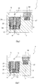
- Fig. 1, 2 . 5 and 6 a first embodiment of an electropneumatic solenoid valve according to the invention is shown, which is generally provided with the reference numeral 1.
- the electro-pneumatic solenoid valve 1 comprises a housing 3 with a lid 5 which is fixed to the housing 3.
- Two air ducts are introduced into the housing structure on a connection wall section 7 of the housing 3 opposite the cover 5, namely an air discharge duct 11 and an air supply duct 13.
- the three air channels 11, 13, 15 are pneumatically connected to an air chamber 17, which is bounded in part by an inner wall surface of the housing 3.
- the air space 17 is cylindrical and additionally bounded by a magnetic rim structure of an electromagnetic actuator 21, which will be explained later.
- a plate-shaped impact valve member 23 is movably mounted floating.
- the impact valve member 23 comprises a planar baffle plate 25 of magnetic, in particular soft magnetic, material, wherein the baffle plate 25 comprises two flat plate surfaces 27, 29, is arranged perpendicular to the axial direction of adjustment S, along which the electromagnetic actuator 21, the impact valve member 23.
- the air supply duct 13 extends coaxially to the axial adjustment direction S, wherein the course of the discharge channel 11 in the connection section 7 of the housing 3 also extends in the axial adjustment direction S but is offset radially to the air supply channel 13. As already indicated above, both air channels 11, 13 open into the air chamber 17.
- a recess is provided, in which a spherical closure element 31 made of a non-magnetic material, such as ceramic, used and attached, in particular pressed, is.
- the spherical closure element 31 protrudes in the axial direction on both plate surfaces 27, 29, on a side 27 at the radial height of the feed channel 13, facing on the other side 29 at the radial height of the mouth region of the vent channel 15 in a coil core 33 of the electromagnetic Adjusting device 21 is introduced.
- the semispherical or partially spherical, protruding closure elements projecting from the flat baffle plate 25 are dimensioned such that they can engage in the corresponding stop position in the mouth region of the respective air channel 13, 15 substantially airtight, on the one hand the venting of the electro-pneumatic solenoid valve.
- the electromagnetic actuator 21 comprises a coil 37 which surrounds the spool core 33 in the circumferential direction.
- the coil 37 is connected to an electrical actuation source in particular via a positioner or control device and receives electrical control signals to magnetically actuate the magnetizable baffle plate 25 of the baffle valve member 23.
- Fig. 1 the state of attraction is shown in which the coil 37 is activated and can be reached via the magnetic closure on the impingement-valve member-side section of the magnetized coil core 33 and the coil jacket 39 surrounding the coil 37 on the outside.
- Fig. 2 the inactive spool 37 is shown and the impact valve member 23 is pressed against the mouth edge of the feed channel 13 due to the spring 41 formed as a constraining means in order to close it airtight ( Fig. 2 ).
- the baffle valve member 23 is floating within the air chamber 17, ie the single forces acting on the baffle valve member 23 are optionally the electromagnetic forces of the actuator, if activated, and the constant compression spring force of the spring 41 and the weight of the baffle valve member itself ( depending on the orientation of the solenoid valve with respect to the direction of gravity).
- An additional guide to the axial Relocating the impact valve member 23 in the axial direction of adjustment S is not necessary.
- the impact valve member when it is stationary in the respective end position (closure of the supply line of the feed channel 13 / closure of the vent channel 15), because the spherical closure element 33 fits self-centering in the mouth of the respective air channel.
- no further guidance is provided on the way from the one end position to the other air channel closing position, in order to set the impact valve member 23 axially within the air chamber.
- a magnetic field is electromagnetically constructed, which is to actuate the impact valve member 23 depending on the determination of the electromagnetic actuator.
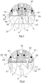
- the solenoid valve in particular the axial displaceability of the impact valve member, are easily checked by a function check mechanism, which is in particular formed by an additional permanent magnet 55, which can be brought from a stowed position to a test position, in particular pivotable.
- the permanent magnet 55 serves to set the magnetizable components of the electromagnetic device in a magnetic field and to check whether then the impact valve member 23 is placed axially.
- An energization of the electromagnetic actuator 21 is not necessary in the function check due to the additional use of the permanent magnet 55.
- the stowage state of the permanent magnet 55 is in Fig. 1 shown.
- the active test state is not shown in detail in the figures.
- the permanent magnet 55 is located in the axial direction adjacent to (above) the electromagnetic actuator 21.
- this is a soft magnetic fixing member 57 opposite, whereby the permanent magnet 55 is held under the influence of its magnetic force in position.
- the holding forces In order to pivot the permanent magnet 55 in the active position, which is not shown in detail, the holding forces must be overcome.
- the permanent magnet 55 In the test position in which the permanent magnet 55 is "activated or activated", the permanent magnet 55 is diametrically on the opposite side of the baffle plate 25 and actuates them magnetically contactless. This way you can visually check whether the baffle plate 25, depending on the position of the permanent magnet 55, the respective air channel 13, 15 closes.
- the stopper plate sections 49, 53 are not necessarily occurring during normal operation stops, since the floating bearing due to the prevailing forces well balanced is, so that a stop with respect to the design of the closing element 31 and the respective mouth areas of the air ducts 13, 15 is adjusted, so that a stop is not considered. Only with exceptional load, such as impact load, may be a stop with regard to the said plate sections.
- This circumferential gap exists when the plate 25 of the baffle valve member 23 is aligned perpendicular to the actuating direction axis S.
- Fig. 5 represents the state of the airtight seal of the vent passage 15, the circumferential axial distance a, which is constant in particular in the entire circumferential direction, slightly smaller than the axial distance b of the baffle plate 25 with respect to the end face 45 of the coil 33.
- the axial gap a ⁇ (smaller than or equal to) half of the axial distance b.
- the axial distance a should not be greater than 0.1 mm, 0.2 mm, 0.3 mm or 1 mm.
- the spring 41 takes over the operation of the impact valve member 23 and presses the latter against the inside of the connection wall portion 7 of the housing 3, whereby the facing spherical closure element 31 airtightly engages against the mouth of the feed channel 13. In this way, the air supply through the air passage 13 is prevented, and the discharge channel 11 is pneumatically connected to the vent passage 15, whereby the electro-pneumatic solenoid valve 1 is vented. It can be seen that the position of the baffle plate 25 of the baffle valve member 23 due to the engagement of the spherical closure member 31 in the mouth of the air supply duct 13 in combination with the compressive forces of the positive spring 41 ensures a stable airtight end position of the baffle valve plate.
- a guide pin 51 is fixed to the connection portion 7 and projects into the air chamber 17.
- This guide pin 51 is primarily not used to guide the baffle valve member 23 during normal operation of the reciprocating the baffle valve member 23 in the axial direction of adjustment S. Rather, should be provided with the insertion of the pin, an axial guide 51 to the effect that the radial position of the baffle valve member is secured in jerky overload movements on the solenoid valve, for example, during transport or assembly to avoid misalignment of the baffle valve member 23.
- these guide pins 51 can be omitted, even if the radial distance r between the annular outer edge of the plate 25 of the impact valve member 23 and the opposite cylindrical inner wall side of the housing 3 of the air chamber 17 allows only a slight radial movement.
- pin in addition to the individual in 3 and 4 shown pin can also be provided several pins without they perform a leadership function.
- On the pins can preferably be dispensed with.
- the radial distance or gap r is less than 2 mm, preferably none than 1 mm, 0.5 mm or 0.2 mm.
- the baffle valve member 23 shown in the figures is preferably made of a soft magnetic material, such as metal, preferably ferrite, to receive attractive forces by the electromagnetic actuator.
- a soft magnetic material such as metal, preferably ferrite
- the magnetic impingement valve member may be provided with a coating of non-magnetic material, such as Teflon, which avoids sticking.
- the baffle plate 25 may also be realized by a non-metallic material, such as plastic, which is provided with metallic particles for absorbing attractive forces. With such a plastic impact valve member design, a non-magnetic coating may be dispensed with.
- the air chamber is more or less a cylindrical gap with an axial depth of slightly greater, preferably three or four times, less than five times the axial thickness of the plate 25 of the impingement valve member 23 executed. In this way, a tilting of the floating-mounted impact valve member 23 is hindered in particular during assembly and transport.
- the radial stops such as the inside of the housing 3, and the axial stops, as in the coil shell 43 and the coil core 33, in particular their end faces and the opposite radially extending inner wall surfaces, do not serve to guide the impact valve member.
- solenoid valve 1 can be used in particular for use in positioners and in combination with pneumatic drives which are simple and double-acting.
Abstract
Bei einem elektropneumatischen Magnetventil (1) für ein pneumatisch betriebenes Feldgerät, insbesondere Stellgerät, einer prozesstechnischen Anlage, wie einer chemischen Anlage, einer petrochemischen Anlage, einer Lebensmittel verarbeitenden Anlage, wie einer Brauerei, einer Kernkraftwerkanlage oder dergleichen, umfassend: einen Luftzuführkanal (13), einen Luftabführkanal (11) und einen Entlüftungskanal (15), wobei die Luftkanäle in eine Luftkammer (17) münden; ein Prallventilglied (23), wie eine Prallplatte (25); eine elektromagnetische Stelleinrichtung (21), die das Prallventilglied zum Be- und/oder Entlüften des Luftabführkanals in einer axialen Stellrichtung (S) verlagert; ein Zwangsmittel, wie eine Feder (41), das das Prallventilglied in der axialen Stellrichtung in eine Schließstellung zum Abschließen eines der Luftkanäle, wie des Zuführkanals, zwingt, ist vorgesehen, dass das Prallventilglied ein insbesondere auf der Stellrichtungsachse liegendes Verschlusselement (31) umfasst, das zum Verschließen des Luftkanals mit einer Begrenzungsinnenwandmündung des Luftkanals derart in Eingriff kommt, dass das Prallventilglied in einem umlaufenden Axialabstand zur Begrenzungsinnenwand angeordnet ist, wobei das Prallventilglied außer durch das Zwangsmittel in der Luftkammer führungslos schwimmend gelagert ist.In an electropneumatic solenoid valve (1) for a pneumatically operated field device, in particular actuating device, a process plant, such as a chemical plant, a petrochemical plant, a food processing plant, such as a brewery, a nuclear power plant or the like, comprising: an air supply duct (13) an air discharge passage (11) and a vent passage (15), the air passages opening into an air chamber (17); an impact valve member (23) such as a baffle plate (25); an electromagnetic actuator (21) which displaces the baffle valve member for loading and / or venting the Luftabführkanals in an axial direction of adjustment (S); a positive means, such as a spring (41), which forces the impact valve member in the axial direction of adjustment to a closed position for closing off one of the air ducts, such as the feed channel, is provided, that the impact valve member comprises a closing element (31) lying in particular on the actuator axis, which is for closing the air passage with a boundary inner wall of the mouth of the air channel engages such that the impact valve member is arranged in a circumferential axial distance from the boundary inner wall, wherein the impact valve member is floating without guidance except by the coercion means in the air chamber guidance.
Description
Die Erfindung betrifft ein elektropneumatisches Magnetventil für ein pneumatisch betriebenes Feldgerät, insbesondere Stellgerät, wie einen Stellungsregler, einer prozesstechnischen Anlage, wie einer chemischen Anlage, einer petrochemischen Anlage, einer Lebensmittel verarbeitenden Anlage, wie einer Brauerei, einer Kernkraftwerkanlage oder dergleichen.The invention relates to an electropneumatic solenoid valve for a pneumatically operated field device, in particular actuating device, such as a positioner, a process plant, such as a chemical plant, a petrochemical plant, a food processing plant, such as a brewery, a nuclear power plant or the like.
Das gattungsgemäße, elektropneumatische Magnetventil hat eine Gehäusestruktur, in der üblicherweise ein Luftzuführkanal, zum Anschließen an eine Luftdruckquelle, ein Luftabführkanal und ein Entlüftungskanal gebildet ist. Ein Prallventilglied, wie eine Prallplatte, ist innerhalb einer Luftkammer beweglich gelagert. Eine elektromagnetische Stelleinrichtung verlagert das Prallventilglied insbesondere zwischen zwei Betriebsstellungen, in der jeweils einer der Luftkanäle verschlossen ist. Das Prallventilglied wird üblicherweise in einer axialen Stellrichtung verlagert. Des Weiteren hat das Magnetventil ein Zwangsmittel, wie eine Feder, das das Prallventilglied in axialer Stellrichtung in eine Schließstellung zum Abschließen eines der Luftkanäle zwingt. Das Prallventilglied hat eine magnetische Prallplatte, die außer durch das Zwangsmittel in der Luftkammer führungslos schwimmend gelagert ist.The generic, electro-pneumatic solenoid valve has a housing structure in which usually an air supply duct, for connection to an air pressure source, an air discharge and a vent channel is formed. An impact valve member, such as a baffle plate, is movably supported within an air chamber. An electromagnetic actuating device displaces the impact valve member in particular between two operating positions, in each of which one of the air ducts is closed. The baffle valve member is usually displaced in an axial direction of adjustment. Furthermore, the solenoid valve has a positive means, such as a spring, which forces the baffle valve member in the axial direction of adjustment into a closed position for closing one of the air ducts. The baffle valve member has a magnetic baffle that is floatingly guided in the air chamber except by the coercive means.
Ein derartiges elektropneumatisches Magnetventil mit einer Prallplatte als Prallventilglied ist aus
Es ist Aufgabe der Erfindung, die Nachteile des Standes der Technik zu überwinden, insbesondere ein elektropneumatisches Magnetventil für ein pneumatisch betriebenes Feldgerät insbesondere der gattungsgemäßen Art derart zu verbessern, dass selbst bei unterschiedlichsten Betriebssituationen, eine präzise Funktionsweise des elektropneumatischen Magnetventils einfachen Aufbaus gewährleistet ist.It is an object of the invention to overcome the disadvantages of the prior art, in particular an electropneumatic solenoid valve for a pneumatically operated field device In particular, to improve the generic type such that even in very different operating situations, a precise operation of the electro-pneumatic solenoid valve simple construction is guaranteed.
Diese Aufgabe wird durch die Merkmale von Anspruch 1 gelöst.This object is solved by the features of
Danach ist ein elektropneumatisches Magnetventil für ein pneumatisch betriebenes Feldgerät, insbesondere Stellgerät, einer prozesstechnischen Anlage, wie einer chemischen Anlage, einer petrochemischen Anlage, einer Lebensmittel verarbeitenden Anlage, wie einer Brauerei, einer Kernkraftwerkanlage oder dergleichen, vorgesehen. Das Magnetventil hat einen Luftzuführkanal insbesondere zum Anschließen an einer Luftdruckquelle, beispielsweise von konstant 6 (sechs) bar. An dem Luftzuführkanal kann auch ein geregeltes Luftsignal beispielsweise von einem elektropneumatischen Stellungsregler angeschlossen sein. Des Weiteren hat das Magnetventil einen Luftabführkanal zum Anschluss beispielsweise an einen pneumatischen Stellantrieb, der einfach oder doppelwirkend sein kann. Insbesondere im Hinblick auf einen Notschließbetrieb kann das Magnetventil zusätzlich einen Entlüftungskanal aufweisen. Das Magnetventil definiert teilweise durch seine Gehäusestruktur eine Luftkammer, in die die Luftkanäle münden. Die Luftkammer ist vorzugsweise außer von der Gehäuseinnenstruktur des Magnetventils auch durch zu magnetisierende Strukturen (deren insbesondere axiale Begrenzungsflächen) begrenzt, welche zum Beispiel der Spulenkern oder der Spulenmantel ist. Vorzugsweise ist in dem Spulenkern einer der Luftkanäle, wie der Entlüftungskanal, ausgebildet. Zum Freigeben und Schließen des jeweiligen Luftkanals hat das elektropneumatische Magnetventil gemäß der Erfindung ein Prallventilglied, wie eine magnetisierbare Prallplatte, die insbesondere zueinander parallele, ebene Plattenseiten definiert, und eine elektromagnetische Stelleinrichtung, die das Prallventilglied zum Be- und/oder Entlüften des Luftabführkanals in einer axialen Stelleinrichtung verlagert. Die elektromagnetische Stelleinrichtung ist vorzugsweise durch eine elektrisch zu versorgende Spule gebildet, die den Spulenkern aus Metall radial umgibt und hat zum Aufbau eines geschlossenen Magnetkreises einen die Spule radial umgebenden Spulenmantel, welche Komponenten beispielsweise näher in den Figuren dargestellt sind. Des Weiteren hat das Magnetventil ein zusätzliches, insbesondere mechanisches, Zwangsmittel, wie eine Druckfeder, oder eine magnetische Zwangsbetätigung, das/die das Prallventilglied in Stellrichtung in eine Schließstellung zum Abschließen eines der Luftkanäle zwingt. Vorzugsweise kann die elektromagnetische Stelleinrichtung das Prallventilglied zwischen zwei Betriebsstellungen, insbesondere Schließstellungen, bewegen, in der einerseits der Luftzuführkanal oder Luftabführkanal und andererseits der Entlüftungskanal durch das Prallventilglied luftdicht verriegelt ist. Erfindungsgemäß hat das Prallventilglied ein insbesondere auf der Stellrichtungsachse liegendes Verschlusselement, das zum Verschließen eines der Luftkanäle insbesondere mit einem Begrenzungsmündungsrand des Luftkanals derart in Eingriff kommt, dass das Prallventilglied in einem umlaufenden Axialabstand, insbesondere konstant umlaufender Ringabstand, zur axial benachbarten Begrenzungsinnenwand der Luftkammer angeordnet ist und gehalten ist, so dass das Prallventilglied selbst bei Radialstößen in der Verschlussstellung unverrückbar bleibt. Auf diese Weise ist sichergestellt, dass das Prallventilglied in der Verschlussstellung insbesondere ausschließlich mit dem Begrenzungsmündungsrand dichtend in Kontakt steht, um ein sicheres und luftdichtes Abschließen des Luftkanals zu gewährleisten. Ein weiterer Kontakt zu der Begrenzungsinnenwand ist aufgrund des umlaufenden Axialabstands ausgeschlossen.Thereafter, an electropneumatic solenoid valve for a pneumatically operated field device, in particular actuating device, a process engineering plant, such as a chemical plant, a petrochemical plant, a food processing plant, such as a brewery, a nuclear power plant or the like, is provided. The solenoid valve has an air supply duct, in particular for connection to an air pressure source, for example, of a constant 6 (six) bar. At the air supply duct and a regulated air signal can be connected for example by an electropneumatic positioner. Furthermore, the solenoid valve has a Luftabführkanal for connection to, for example, a pneumatic actuator, which may be single or double acting. In particular with regard to an emergency closing operation, the solenoid valve may additionally have a ventilation channel. Partially through its housing structure, the magnetic valve defines an air chamber into which the air ducts open. The air chamber is preferably limited except by the internal structure of the housing of the solenoid valve by structures to be magnetized (in particular their axial boundary surfaces), which is for example the coil core or the coil jacket. Preferably, one of the air ducts, such as the venting channel, is formed in the coil core. To release and close the respective air duct, the electro-pneumatic solenoid valve according to the invention has an impact valve member, such as a magnetizable baffle plate, which defines in particular parallel, flat plate sides, and an electromagnetic actuator, the impact valve member for loading and / or venting the Luftabführkanals in a shifted axial actuator. The electromagnetic setting device is preferably formed by a coil to be electrically supplied, which radially surrounds the coil core of metal and has to build a closed magnetic circuit a coil surrounding the coil radially, which components are shown for example in more detail in the figures. Furthermore, the solenoid valve has an additional, in particular mechanical, positive means, such as a compression spring, or a magnetic forced operation, which forces the impact valve member in the direction of adjustment into a closed position for closing one of the air channels. Preferably, the electromagnetic control device, the impact valve member between two operating positions, in particular closed positions, move, in the one hand the Air supply duct or Luftabführkanal and on the other hand, the vent passage through the impingement valve member is airtightly locked. According to the invention the baffle valve member has a particular lying on the Stellrichtungsachse closure element which comes to close one of the air ducts in particular with a Begrenzungsmündungsrand the air channel in such a way that the baffle valve member is arranged in a circumferential axial distance, in particular constant circumferential ring spacing to the axially adjacent boundary inner wall of the air chamber and is held so that the impact valve member remains immovable even in radial shocks in the closed position. In this way, it is ensured that the baffle valve member in the closed position in particular is sealingly in contact exclusively with the boundary mouth edge in order to ensure a secure and airtight closing of the air duct. Another contact with the boundary inner wall is excluded due to the circumferential axial distance.
Es sei klar, dass der umlaufende Axialabstand sich insbesondere dann einstellt, wenn das Prallventilglied in einer insbesondere lotrechten Lage zur Stellrichtungsachse ausgerichtet ist. Dabei ist das Prallventilglied im Hinblick auf den Mündungsrand des zu verschließenden Luftkanals derart dimensioniert, dass ein selbstständiges Ausrichten des Prallventilglieds bei dessen Verlagerung in die Verschlussposition insbesondere unter dem Einfluss der elektromagnetischen Kräfte und/oder des Zwangsmittels veranlasst wird. Vorzugsweise sind der zu verschließende Luftkanal und dessen Mündungsrand in der Luftkammerbegrenzungswand als Ventilsitzbohrung ausgeführt. Das Prallventilglied, die Sitzbohrung, insbesondere sich gegenüberliegende Sitzbohrungen, und ein insbesondere axialer Maximalhub des Prallventilglieds in der Luftkammer sind so dimensioniert/ausgelegt, dass das Prallventilglied, insbesondere im Bereich der Sitzbohrungen, insbesondere durch den Begrenzungsrand der Gehäusestruktur / einer Kernstruktur der elektromagnetischen Stelleinrichtung, gehalten wird und beim Betätigen/Schließen sich insbesondere selbstständig mittig der Sitzbohrung zentriert. In dem insbesondere unbetätigten Betrieb bilden die Bohrungsränder der Sitzbohrung die Haltestruktur, gegen die das Prallventilglied trifft, um in Radialrichtung gehalten zu werden. Beim Betätigen/Schließen des insbesondere kugelförmigen Prallventilglieds tritt die automatische Zentrierung ein.It is clear that the circumferential axial distance is set in particular when the impact valve member is aligned in a particular vertical position to the actuating direction axis. In this case, the impact valve member is dimensioned with respect to the mouth edge of the air duct to be closed such that an independent alignment of the baffle valve member is caused in its displacement into the closure position, in particular under the influence of the electromagnetic forces and / or the coercive agent. Preferably, the air duct to be closed and its mouth edge in the air chamber boundary wall are designed as a valve seat bore. The impact valve member, the seat bore, in particular opposite seat bores, and a particular axial maximum stroke of the baffle valve member in the air chamber are dimensioned / designed such that the baffle valve member, in particular in the region of the seat bores, in particular by the boundary edge of the housing structure / a core structure of the electromagnetic actuator, is held and centered when operating / closing in particular independently center of the seat bore. In the particular unactuated operation, the bore edges of the seat bore form the support structure against which the impact valve member strikes to be held in the radial direction. Upon actuation / closing of the particular spherical impact valve member, the automatic centering occurs.
Bei einer anderen Dimensionierung des Ventilsystems kann es aufgrund der schwimmenden Lagerung des Prallventilglieds durchaus sein, dass das Prallventilglied bei einer Schrägstellung bezüglich der Stellrichtungsachse, die beispielsweise durch eine außergewöhnliche Betriebssituation, wie eine Schlagbelastung auf das Magnetventil, einhergehen kann, in axialen Kontakt mit einer Begrenzungsinnenwand der Luftkammer kommen kann, allerdings nur in einem kleinflächigen Kontaktpunkt, der aber erfindungsgemäß die luftdichte Verschließung des Luftkanals nicht beeinträchtigt.In another dimensioning of the valve system, it may well be due to the floating mounting of the baffle valve member that the baffle valve member at an inclination with respect to the direction of the actuator axis, for example, by an exceptional operating situation, how a shock load on the solenoid valve may be associated with coming into axial contact with a boundary inner wall of the air chamber, but only in a small-area contact point, but which does not affect the airtight closure of the air duct according to the invention.
Die Prallplatte kann derart dimensioniert und strukturiert im Hinblick auf die insbesondere plane Begrenzungsinnenwand der Luftkammer sein, dass sich ein insbesondere konstant umlaufender Axialabstand zur Begrenzungsinnenwand einstellt, insbesondere wenn das plattenförmige Prallventilglied in einer gewünschten lotrechten Lage zur Richtungsachse der elektromagnetischen Stelleinrichtung ausgerichtet ist.The baffle plate can be dimensioned and structured with respect to the particular plane boundary inner wall of the air chamber, that adjusts an especially constant circumferential axial distance to the boundary inner wall, in particular when the plate-shaped baffle valve member is aligned in a desired vertical position to the directional axis of the electromagnetic actuator.
Die Prallplatte ist derart in der Luftkammer anzuordnen, dass eine radiale Berührung der Prallplatte an der Begrenzungswand der Luftkammer ausgeschlossen ist. Ein radialer Kontakt ist vorzugsweise insofern zu vermeiden, als eine erhöhte Reibung, die mit einem Kontakt einhergehen würde, sich negativ hinsichtlich der Funktionsweise auswirken würde. Der radiale Abstand zwischen der Prallplatte und der Begrenzungswand der Luftkammer ist vorzugsweise derart zu wählen, insbesondere zu dimensionieren, dass keine radiale Berührung im Normalbetrieb der Betätigung stattfinden kann. Die magnetische Prallplatte kann im Normalbetrieb derart schwimmend gelagert sein, dass sie in einem Öffnungszustand ausschließlich mit dem Zwangsmittel in einem Berührkontakt steht und dass sie in einem Schließzustand ausschließlich einerseits mit dem Zwangsmittel und andererseits mit einem Ventilsitz oder dergleichen in einem Berührkontakt steht.The baffle plate is to be arranged in the air chamber such that a radial contact of the baffle plate on the boundary wall of the air chamber is excluded. Radial contact is preferably to be avoided insofar as increased friction associated with contact would negatively impact performance. The radial distance between the baffle plate and the boundary wall of the air chamber is preferably to be selected, in particular to be dimensioned such that no radial contact can take place during normal operation of the actuation. The magnetic baffle plate may be stored in such a floating manner in normal operation that it is in an open state exclusively with the coercive means in touching contact and that it is in a closed state exclusively on the one hand with the coercive means and on the other hand with a valve seat or the like in touching contact.
Vorzugsweise ist das Prallventilglied, insbesondere die magnetische Prallplatte, ohne jegliche weitere Führungseinrichtung innerhalb der Luftkammer angeordnet, so dass ein Kontakt des Prallventilglieds mit Begrenzungswandabschnitten der Luftkammer nur im Zentrierbereich des Prallventilglieds einhergeht. Weitere Kontakte des Prallventilglieds, insbesondere der Prallplatte, sollen ausgeschlossen sein. Das Weglassen von weiteren Führungseinrichtungen wie Führungsstifte, bedeutet eine deutliche Reduzierung des Montageaufwands, wobei es sich überraschenderweise herausstellte, dass die Funktionsfähigkeit des schwimmend gelagerten Prallventils nicht beeinträchtigt wird.Preferably, the baffle valve member, in particular the magnetic baffle plate, without any further guide means disposed within the air chamber, so that a contact of the baffle valve member with boundary wall portions of the air chamber is accompanied only in the centering of the baffle valve member. Further contacts of the impact valve member, in particular the baffle plate should be excluded. The omission of other guide means such as guide pins, means a significant reduction in the assembly effort, and it was surprisingly found that the functionality of the floating-mounted impact valve is not affected.
Bei einer bevorzugten Ausführung der Erfindung ist das Verschlusselement als ein insbesondere beidseitig von dem vorzugsweise planen Prallventilglied vorragenden Vorsprung gebildet, der insbesondere zumindest teilweise konvexsphärisch geformt ist. Vorzugsweise ist das Verschlusselement in dem axialen Zentrum einer insbesondere kreisförmigen Prallplatte des Prallventilglieds ausgebildet/angeordnet. Vorzugsweise ist das Verschlusselement als separat in der Prallplatte montierte Kugel ausgebildet und/oder aus einem nichtmagnetischen Material, wie Keramik, gebildet. Vorzugsweise besteht die separat montierte Kugel ausschließlich aus dem nicht magnetischen Material. Auf diese Weise wird der Magnetfluss nicht in Richtung des Verschlusselements gelenkt, sondern davon abgelenkt, so dass der Magnetfluss wegen des nichtmagnetischen Verschlusselementmaterials umgeleitet wird. Ein magnetisches Kleben der Kugel wegen des Restmagnetismus zwischen Kugel und Sitz ist daher verhindert.In a preferred embodiment of the invention, the closure element is formed as a protrusion projecting in particular on both sides from the preferably planar impact valve member, which is in particular at least partially convex-spherical. Preferably, the closure element is formed / arranged in the axial center of a particular circular baffle plate of the baffle valve member. Preferably, the closure element is designed as a ball mounted separately in the baffle plate and / or formed from a non-magnetic material, such as ceramic. Preferably, the separately mounted ball consists exclusively of the non-magnetic material. In this way, the magnetic flux is not directed in the direction of the closure element, but deflected by it, so that the magnetic flux is redirected because of the non-magnetic closure element material. A magnetic sticking of the ball because of the residual magnetism between the ball and seat is therefore prevented.
Bei einer bevorzugten Ausführung der Erfindung hat das Prallventilglied einen radial innenliegenden Innenanschlagsbereich, der dem Spulenkern der elektromagnetischen Stelleinrichtung diametral axial gegenüberliegt, und einen den Innenanschlagsbereich radial außen umgebenden Außenanschlagsbereich, der einen die Spule der elektromagnetischen Stelleinrichtung radial außen umgebenden Spulenmantel der elektromagnetischen Stelleinrichtung oder einem Gehäuseabschnitt des Magnetventils diametral gegenüberliegt. Es sei klar, dass der Außenanschlagsbereich nicht notwendigerweise zur Funktion des Anschlagens dienen muss, allerdings, sollte die schwimmende Lagerung der Prallplatte beispielsweise durch eine vorübergehende Schrägstellung im Montagefall oder bei Schlagbelastung aus der üblichen Verlagerungsstellung und -richtung gelangen, so werden ein außergewöhnlicher Außenanschlag oder Innenschlag ermöglicht, um ein kurzfristiges Verkippen mit begrenzter Kippamplitude zu gewährleisten. Es ist das Zusammenspiel der elektromagnetischen Kraft der elektromagnetischen Stelleinrichtung und/oder des Zwangsmittels im Hinblick auf die Ausführung des Verschlusselements des Prallventilglieds im Zusammenspiel mit dem Mündungsrand des zu verschließenden Verschlusskanals, der das Ausrichten/Halten der Prallplatte zum Ausbilden des kontaktlosen Axialabstands zur Begrenzungswand gewährleistet.In a preferred embodiment of the invention, the baffle valve member has a radially inner Innenanschlagsbereich diametrically opposite to the coil core of the electromagnetic actuator axially, and the Innenanschlagsbereich radially outwardly surrounding Außenanschlagsbereich, the coil of the electromagnetic actuator radially outwardly surrounding the coil jacket of the electromagnetic actuator or a housing portion of the solenoid valve diametrically opposite. It should be understood that the outer fence area does not necessarily have to serve the function of striking, however, should the floating support of the baffle plate, for example, by a temporary inclination in the case of assembly or impact load from the usual displacement position and direction get, so are an exceptional outer or internal impact allows for short-term tilting with limited amplitude of tilt. It is the interaction of the electromagnetic force of the electromagnetic actuator and / or the coercion means with respect to the execution of the closure element of the baffle valve member in cooperation with the mouth edge of the closure channel to be closed, which ensures the alignment / holding of the baffle plate for forming the contactless axial distance to the boundary wall.
Vorzugsweise ist einer der Luftkanäle, wie der Entlüftungskanal, in dem Spulenkern ausgebildet. Insbesondere bei dieser Ausführung des Luftkanals in dem Spulenkern, mit dem der Verschlussbereich dicht verschließend zusammenwirken soll, ist es von Vorteil, das nichtmagnetische Material für das Verschlusselement vorzusehen.Preferably, one of the air ducts, such as the venting channel, is formed in the spool core. In particular, in this embodiment of the air channel in the spool core, with which the closure region is intended to cooperate tightly sealing, it is advantageous to provide the non-magnetic material for the closure element.
Bei einer Weiterbildung der Erfindung sind die Prallplatte und die zugeordneten Anschlagsbereiche derart ausgelegt, strukturiert und/oder dimensioniert, dass bei insbesondere dichtender Belegung des Luftkanals in dem Spulenkern durch das Verschlusselement des Prallventilglieds der radial äußere Axialabstand des Prallventilglieds zum Außenanschlagsbereich kleiner als der innere Axialabstand des Prallventilglieds zum Innenanschlagsbereich ist. Vorzugsweise ist der radial innere Axialabstand bei Belegung des Luftkanals in dem Spulenkern durch das Verschlusselement kleiner als 0,5 mm, 0,3 mm oder 0,1 mm. Vorzugsweise oder alternativ dazu ist der radial äußere Axialabstand um wenigstens ein Drittel, vorzugsweise um etwa die Hälfte, kleiner als der radial innere Axialabstand dimensioniert. Auf diese Weise wird sichergestellt, dass die Kippamplitude des schwimmend gelagerten Prallventilglieds begrenzt ist, insbesondere durch den außenliegenden Anschlag.In a further development of the invention, the baffle plate and the associated stop regions are designed, structured and / or dimensioned in such a way that in particular sealing Occupancy of the air channel in the bobbin by the closure element of the baffle valve member, the radially outer axial distance of the baffle valve member to the outer stop area is smaller than the inner axial distance of the baffle valve member to the Innenanschlagsbereich. Preferably, the radial inner axial distance is less than 0.5 mm, 0.3 mm or 0.1 mm in occupancy of the air channel in the bobbin by the closure element. Preferably or alternatively, the radially outer axial distance is dimensioned at least one-third, preferably by about half, smaller than the radially inner axial distance. In this way it is ensured that the Kippamplitude of the floating-mounted impact valve member is limited, in particular by the outer stop.
Bei einer bevorzugten Ausführung der Erfindung ist koaxial dem Luftkanal, insbesondere dem Entlüftungskanal, in dem Spulenkern ein weiterer Luftkanal, wie der Luftzuführkanal oder der Luftabführkanal, in einer Gehäusewand des Magnetventils derart eingebracht, dass eine Rückseite des Verschlusselements, dessen Vorderseite den Luftkanal in dem Spulenkern verschließt, bei entsprechender axialer Verlagerung des Prallventilglieds unter dem Einfluss des Zwangsmittels den Luftkanal in der Magnetventilgehäusewand verschließt, wobei insbesondere radial versetzt zu dem Luftkanal in der Magnetventilgehäusewand ein weiterer Luftkanal, wie der Luftabführkanal oder Luftzuführkanal, ausgebildet ist, der insbesondere von dem Prallventilglied an keiner axialen Stellposition verschließbar ist. Der radial versetzte Luftkanal ist an keiner axialen Stellposition des Prallventilglieds von dem Prallventilglied verschließbar.In a preferred embodiment of the invention, coaxially with the air duct, in particular the vent duct, in the coil core, another air duct, such as the air supply duct or Luftabführkanal introduced in a housing wall of the solenoid valve such that a rear side of the closure element, the front of the air duct in the spool core closes, closes with appropriate axial displacement of the baffle valve member under the influence of the coercive force the air duct in the solenoid valve housing wall, wherein in particular radially offset from the air duct in the solenoid valve housing wall, a further air duct, such as Luftabführkanal or air supply duct is formed, in particular of the baffle valve member at no axial parking position is closed. The radially offset air channel can not be closed at any axial adjustment position of the impact valve member by the impact valve member.
Vorzugsweise ist die Luftkammer radial durch eine im Wesentlichen zylindrische Kammerinnenwand begrenzt, die zumindest teilweise durch das Magnetventilgehäuse gebildet ist. Die Luftkammer kann axial durch eine seitliche Gehäusewand begrenzt sein, in der wenigstens zwei Luftkanäle eingebracht sind, und die der magnetisierbaren Komponente der elektromagnetischen Stelleinrichtung gegenüberliegt. Es ist diese magnetische Struktur der elektromagnetischen Stelleinrichtung, welche die Luftkammer an der gegenüberliegenden Axialseite begrenzt. In der zylindrischen Luftkammer kann die kreisförmige Prallplatte des Prallventilglieds insbesondere konstanter Prallplattenstärke axial beweglich und insbesondere wie ein Kolben schwimmend gelagert sein. Insbesondere ausschließlich durch das Zwangsmittel ist das Prallventilglied mechanisch geführt. Vorzugsweise ist die axiale maximale Bewegungsamplitude des Prallventilglieds in axialer Stellrichtung höchstens ein Zehntel bis ein Viertel (die Dicke der Prallplatte kann zwischen 0,6 mm und 1mm und der Hub zwischen 0,1 mm und 0,3mm liegen) der insbesondere konstanten axialen Stärke der Prallplatte.Preferably, the air chamber is bounded radially by a substantially cylindrical chamber inner wall, which is at least partially formed by the solenoid valve housing. The air chamber may be bounded axially by a lateral housing wall, in which at least two air channels are introduced, and which is opposite to the magnetizable component of the electromagnetic actuator. It is this magnetic structure of the electromagnetic actuator that limits the air chamber on the opposite axial side. In the cylindrical air chamber, the circular baffle plate of the baffle valve member in particular constant baffle plate thickness can be axially movable and in particular floatingly mounted like a piston. In particular, exclusively by the force means the impact valve member is guided mechanically. Preferably, the axial maximum amplitude of movement of the baffle valve member in the axial direction of adjustment is at most a tenth to a quarter (The thickness of the baffle plate can be between 0.6 mm and 1 mm and the stroke between 0.1 mm and 0.3 mm) of particular constant axial thickness of the baffle plate.
Auf diese Weise ist ein guter Luftaustausch zwischen den beiden von der Prallplatte getrennten Luftkammerabteilen gewährleistet. Die Prallplatte dient dem individuellen Luftkanalverschluss und bewegt sich axial zwischen den sich gegenüberliegenden axialen Begrenzungswänden der Luftkammer, in dem die insbesondere sich axial gegenüberliegenden Luftkanäle angeordnet sind.In this way, a good exchange of air between the two separated from the baffle air chamber compartments is guaranteed. The baffle plate serves the individual air duct closure and moves axially between the opposite axial boundary walls of the air chamber, in which the particular axially opposite air channels are arranged.
Vorzugsweise ist die axiale insbesondere maximale Bewegungsamplitude des Prallventilglieds in axialer Stellrichtung mindestens 1/10, mindestens 1/8 oder mindestens ¼ des Düsendurchmessers und/oder höchstens 9/10, höchstens 2/3, höchstens ½ des Düsendurchmessers. Insbesondere beträgt der Hub bzw. die Bewegungsamplitude zwischen 0,1 mm und 1,5 mm, vorzugsweise zwischen 0,2 mm und 0,6 mm, besonders bevorzugt 0,4 mm. Die Prallplattendicke (Querschnitt) ist vorzugsweise wenigstens so dick, dass Sie bei maximaler Bestromung der Magnetspule noch nicht in die magnetische Sättigung kommt. Insbesondere hat die Prallplatte eine geringe Dicke von weniger als 2 mm, vorzugsweise weniger als 1 mm, besonders bevorzugt weniger als 0,5 mm, um die Masse der Prallplatte klein zu halten.Preferably, the axial, in particular maximum, amplitude of movement of the baffle valve member in the axial adjustment direction is at least 1/10, at least 1/8 or at least 1/4 of the nozzle diameter and / or at most 9/10, at most 2/3, at most 1/2 of the nozzle diameter. In particular, the stroke or the movement amplitude is between 0.1 mm and 1.5 mm, preferably between 0.2 mm and 0.6 mm, particularly preferably 0.4 mm. The baffle plate thickness (cross-section) is preferably at least so thick that it does not yet come into magnetic saturation at maximum energization of the magnetic coil. In particular, the baffle plate has a small thickness of less than 2 mm, preferably less than 1 mm, more preferably less than 0.5 mm, in order to keep the mass of the baffle plate small.
Des Weiteren betrifft die Erfindung ein Prallventilglied zum Anordnen in einer Luftkammer eines insbesondere erfindungsgemäßen elektropneumatischen Magnetventils. Das Prallventilglied hat eine Prallplatte und gegebenenfalls das oben genannte Verschlusselement. Die Prallplatte hat eine axiale Verschlussseite, vorzugsweise zwei sich diametral gegenüberliegende axiale Verschlussseiten, die wenigstens einem zu schließenden oder freizugebenden Luftkanal zuzuwenden ist und zumindest flächenabschnittsweise in Kontakt mit einer von einer elektromagnetischen Stelleinrichtung des Magnetventils zu magnetisierenden, axialen Anlagewand der Luftkammer kommen kann.Furthermore, the invention relates to an impact valve member for arranging in an air chamber of a particular inventive electro-pneumatic solenoid valve. The impact valve member has a baffle plate and optionally the above-mentioned closure element. The baffle plate has an axial closure side, preferably two diametrically opposed axial closure sides, which is at least turn to be closed or released air duct and at least surface sections in contact with one of an electromagnetic actuator of the solenoid valve to be magnetized, axial abutment wall of the air chamber.
In der Anlagewand ist der wenigstens eine Luftkanal ausgebildet. Erfindungsgemäß ist die wenigstens eine Verschlussaußenseite, vorzugsweise beide sich axial diametral gegenüberliegenden Verschlussaußenseiten, zumindest flächenabschnittsweise, mit einem nicht magnetisierbaren Material, wie Teflon, ausgebildet, insbesondere mit einer nicht magnetisierbaren Deckschicht, wie einer Teflonschicht, versehen. Erfindungsgemäß wird erreicht, dass ein magnetisches Ankleben auch nach der Deaktivierung der elektromagnetischen Stelleinrichtung insbesondere an dem magnetisierten Bestandteil der elektromagnetischen Stelleinrichtung, wie dem Spulenkern und/oder dem Spulenmantel, verhindert ist. Der Klebevermeidungseffekt wird also mittels eines Materials erreicht, das nicht magnetisierbar ist und an der Außenkontaktseite der Prallplatte vorgesehen ist. Dabei ist allerdings zu gewährleisten, dass die Prallplatte per se magnetisierbar bleibt. Insofern kann ein nicht magnetisierbares Material die Außenseite der Prallplatte bilden, wobei beispielsweise zumindest ein Kernbereich magnetisierbar ist oder magnetisierbare Teilchen innerhalb eines nicht magnetisierbaren Materials enthalten sind.In the investment wall of at least one air channel is formed. According to the invention, the at least one outer closure side, preferably both axially diametrically opposite outer closure sides, at least in areas, with a non-magnetizable material, such as Teflon trained, in particular with a non-magnetizable cover layer, such as a Teflon layer provided. According to the invention it is achieved that a magnetic sticking even after the deactivation of the electromagnetic actuator in particular on the magnetized component of the electromagnetic actuator, such as the spool core and / or the coil jacket is prevented. The adhesive avoidance effect is thus achieved by means of a material which is not magnetizable and is provided on the outer contact side of the baffle plate. However, it must be ensured that the baffle plate remains magnetizable per se. In this respect, a non-magnetizable material form the outside of the baffle plate, wherein, for example, at least one core region is magnetizable or magnetizable particles are contained within a non-magnetizable material.
Weitere Aspekte der Erfindung sind in den Unteransprüchen angegeben.Further aspects of the invention are specified in the subclaims.
Weitere Vorteile, Merkmale und Aspekte der Erfindung sind durch die folgende Beschreibung bevorzugter Ausführungen der Erfindung anhand der beiliegenden Zeichnungen erläutert, in den zeigen:
- Fig. 1
- eine Querschnittsansicht eines erfindungsgemäßen elektropneumatischen Magnetventils, bei dem die elektromagnetische Stelleinrichtung aktiviert ist, um das Prallventilglied anzuziehen und einen stelleinrichtungsseitigen Luftkanal zu verschließen;
- Fig. 2
- eine Querschnittsansicht des elektropneumatischen Magnetventils nach
Fig. 1 , in dem die elektromagnetische Stelleinrichtung deaktiviert wird und das als Feder ausgebildete Zwangsmittel das Prallventilglied an die gegenüberliegende Seitenwand mit zwei Luftkanälen drückt; - Fig. 3
- eine Detailquerschnittsansicht einer weiteren Ausführung des erfindungsgemäßen Magnetventils mit aktivierter elektromagnetischer Stelleinrichtung;
- Fig. 4
- die Querschnittsdetailansicht gemäß
Fig. 3 , wobei die elektromagnetische Stelleinrichtung deaktiviert ist; - Fig. 5
- eine Querschnittsdetailansicht der Ausführung des erfindungsgemäßen Magnetventils nach
Fig. 1, 2 mit der aktivierten elektromagnetischen Stelleinrichtung; - Fig. 6
- die Querschnittsansicht nach
Fig. 5 , wobei die elektromagnetische Stelleinrichtung deaktiviert ist.
- Fig. 1
- a cross-sectional view of an electropneumatic solenoid valve according to the invention, wherein the electromagnetic actuator is activated to attract the baffle valve member and to close a feeder-side air channel;
- Fig. 2
- a cross-sectional view of the electro-pneumatic solenoid valve according to
Fig. 1 in which the electromagnetic actuator is deactivated and the spring means of urging the impact valve member presses against the opposite side wall with two air channels; - Fig. 3
- a detail cross-sectional view of another embodiment of the solenoid valve according to the invention with activated electromagnetic actuator;
- Fig. 4
- the cross-sectional detail view according to
Fig. 3 wherein the electromagnetic actuator is deactivated; - Fig. 5
- a cross-sectional detailed view of the embodiment of the solenoid valve according to the invention
Fig. 1, 2 with the activated electromagnetic actuator; - Fig. 6
- the cross-sectional view after
Fig. 5 , wherein the electromagnetic actuator is deactivated.
In
Das elektropneumatische Magnetventil 1 umfasst ein Gehäuse 3 mit einem Deckel 5, der an dem Gehäuse 3 befestigt ist. An einem dem Deckel 5 gegenüberliegenden Anschlusswandabschnitt 7 des Gehäuses 3 sind zwei Luftkanäle in die Gehäusestruktur eingebracht, nämlich ein Luftabführkanal 11 und ein Luftzuführkanal 13. Benachbart dem Deckel 5 ist ein weiterer Luftkanal in der Gehäusestruktur 3 eingearbeitet und mit der Bezugsziffer 15 angedeutet. Dieser Luftkanal ist der Entlüftungskanal 15, der ungehindert an die Außenseite des Gehäuses 3 mündet.The electro-
Die drei Luftkanäle 11, 13, 15 sind pneumatisch mit einer Luftkammer 17 verbunden, welche zum Teil von einer Innenwandfläche des Gehäuses 3 begrenzt ist.The three
Der Luftraum 17 ist zylindrisch und zusätzlich von einer magnetischen Einfassstruktur einer später noch erläuterten elektromagnetischen Stelleinrichtung 21 begrenzt. In dem zylindrischen Luftraum 17 ist kolbengemäß ein plattenförmiges Prallventilglied 23 beweglich schwimmend gelagert angeordnet. Das Prallventilglied 23 umfasst eine ebene Prallplatte 25 aus magnetischen, insbesondere weichmagnetischem, Material, wobei die Prallplatte 25 zwei ebene Plattenflächen 27, 29 umfasst, zu der lotrecht die axiale Stellrichtung S angeordnet ist, längs der die elektromagnetische Stelleinrichtung 21 das Prallventilglied 23 stellt.The
Der Luftzuführkanal 13 verläuft koaxial zur axialen Stellrichtung S, wobei der Verlauf des Abführkanals 11 im Anschlussabschnitt 7 des Gehäuses 3 sich auch in axialer Stellrichtung S erstreckt aber zum Luftzuführkanal 13 radial versetzt angeordnet ist. Wie bereits oben angedeutet ist, münden beide Luftkanäle 11, 13 in die Luftkammer 17.The
In der zentralen Mitte der insbesondere kreisförmigen Prallplatte 25 ist eine Aussparung vorgesehen, in die ein kugelförmiges Verschlusselement 31 aus einem nichtmagnetischen Material, wie Keramik, eingesetzt und befestigt, insbesondere eingepresst, ist.In the central center of the particular
Das kugelförmige Verschlusselement 31 steht an beiden Plattenflächen 27, 29 in Axialrichtung vor, auf einer Seite 27 auf radialer Höhe des Zuführkanals 13, diesem zugewandt, auf der anderen Seite 29 auf radialer Höhe des Mündungsbereichs des Entlüftungskanals 15, der in einem Spulenkern 33 der elektromagnetischen Stelleinrichtung 21 eingebracht ist. Die halb- oder teilsphärischen, vorragenden Verschlusselemente, die von der ebenen Prallplatte 25 vorstehen, sind derart dimensioniert, dass sie im Wesentlichen luftdicht bei der entsprechenden Anschlagsposition in den Mündungsbereich des jeweiligen Luftkanals 13, 15 eingreifen können, um einerseits die Entlüftung des elektropneumatischen Magnetventils 1 (geschlossener Entlüftungskanal 15) zu vermeiden, andererseits die weitere Zufuhr von Druckluft einer nicht dargestellten Druckluftquelle über die Zuführleitung 13 zu vermeiden. Dabei ist der axiale Maximalhub H des Prallventilglieds 23 derart durch die axialen Begrenzungswände begrenzt, dass die beidseitig vorstehenden Verschlusselemente einen Kontakt der Prallplatte 25 mit dem Gehäuse vermeiden, da das jeweilige Verschlusselement erst in Eingriffkontakt mit dem Mündungsrand des jeweiligen Luftkanals 13 oder 15 kommt. Ein axiales Austreten aus der Eingriffssphäre des Mündungsrands wird in allen axialen Positionen des Verschlusselements ausgeschlossen, was insbesondere durch die teilsphärische Form des Verschlusselements realisiert ist.The
Die elektromagnetische Stelleinrichtung 21 umfasst eine Spule 37, welche den Spulenkern 33 in Umfangsrichtung umgibt. Die Spule 37 ist an eine elektrische Betätigungsquelle insbesondere über eine Stellungs- oder Regelungseinrichtung angeschlossen und empfängt elektrische Stellsignale, um die magnetisierbare Prallplatte 25 des Prallventilglieds 23 magnetisch zu betätigen. In
Das Prallventilglied 23 ist innerhalb der Luftkammer 17 schwimmend gelagert, d.h. die einzigen Kräfte, die auf das Prallventilglied 23 wirken, sind gegebenenfalls die elektromagnetischen Kräfte der Stelleinrichtung, falls diese aktiviert sind, und die ständige Druckfederkraft der Feder 41 und die Gewichtskraft des Prallventilglieds selbst (je nach Ausrichtung des Magnetventils bezüglich der Gravitationsrichtung). Eine zusätzliche Führung zum axialen Verlagern des Prallventilglieds 23 in axialer Stellrichtung S ist nicht notwendig. Überraschenderweise zeigte es sich, dass nicht einmal eine Befestigung der an der Prallplatte 25 anliegenden Federwindung an der Prallplatte 25 befestigt sein muss, sondern lediglich die Druckkräfte im Zusammenspiel mit den elektropneumatischen Kräften der Stelleinrichtung reichen dazu aus, die Positionierung des Prallventilglieds sicherzustellen. Selbstverständlich ist das Prallventilglied, wenn es in der jeweiligen Endposition (Verschluss der Zuführleitung des Zuführkanals 13 / Verschluss des Entlüftungskanals 15) ortsfest angeordnet ist, weil das sphärische Verschlusselement 33 sich in den Mündungskanal des jeweiligen Luftkanals selbstzentrierend einpasst. Allerdings ist auf dem Weg von der einen Endposition zur anderen Luftkanalverschlussposition keine weitere Führung vorgesehen, um das Prallventilglied 23 innerhalb der Luftkammer axial zu stellen.The
Zur Betätigung des Prallventilglieds 23 wird ein Magnetfeld elektromagnetisch aufgebaut, das das Prallventilglied 23 abhängig von der Bestimmung der elektromagnetischen Stelleinrichtung betätigen soll. Unabhängig von der elektromagnetischen Stelleinrichtung kann das Magnetventil, insbesondere die axiale Verlagerbarkeit des Prallventilglieds, einfach anhand eines Funktionsüberprüfungsmechanismus überprüft werden, der insbesondere durch einen zusätzlichen Dauermagnet 55 gebildet ist, der von einer Verstauungsposition in eine Prüfposition verbringbar, insbesondere verschwenkbar ist. Der Dauermagnet 55 dient dazu, die magnetisierbaren Komponenten der elektromagnetischen Einrichtung in ein Magnetfeld zu setzen und zu überprüfen, ob daraufhin das Prallventilglied 23 axial gestellt wird. Eine Bestromung der elektromagnetischen Stelleinrichtung 21 ist bei der Funktionsüberprüfung aufgrund des zusätzlichen Einsatzes des Dauermagneten 55 nicht notwendig. Der Verstauungszustand des Dauermagneten 55 ist in
Um den Dauermagneten 55 in der Passivposition (
Wie in
Wie ebenfalls in
In der in
Bei allmählicher Abnahme der elektromagnetischen Kraft oder vollständigen Abschaltens der elektromagnetischen Einrichtung 21 übernimmt die Zwangsfeder 41 die Betätigung des Prallventilglieds 23 und drückt letzteres gegen die Innenseite des Anschlusswandabschnitts 7 des Gehäuses 3, wodurch das zugewandte sphärische Verschlusselement 31 luftdicht gegen die Mündung des Zuführkanals 13 eingreift. Auf diese Weise ist die Luftzufuhr über den Luftkanal 13 verhindert, und der Abführkanal 11 ist mit dem Entlüftungskanal 15 pneumatisch verbunden, wodurch das elektropneumatische Magnetventil 1 entlüftet ist. Es zeigt sich, dass die Position der Prallplatte 25 des Prallventilglieds 23 aufgrund des Eingriffs des sphärischen Verschlusselements 31 in die Mündung des Luftzuführkanals 13 in Kombination mit den Druckkräften der Zwangsfeder 41 eine stabile luftdichte Endposition der Prallventilplatte gewährleistet.With gradual decrease of the electromagnetic force or complete shutdown of the
In
Es sei klar, dass neben dem einzelnen in
Vorzugsweise ist der Radialabstand oder -spalt r kleiner als 2 mm, vorzugsweise keiner als 1 mm, 0,5 mm oder 0,2 mm.Preferably, the radial distance or gap r is less than 2 mm, preferably none than 1 mm, 0.5 mm or 0.2 mm.
Das in den Figuren dargestellte Prallventilglied 23 ist vorzugsweise aus einem weichmagnetischen Material, wie Metall, vorzugsweise Ferrit, um Anziehungskräfte durch die elektromagnetische Stelleinrichtung aufzunehmen. Es zeigte sich allerdings bei metallischen Prallventilgliedern, insbesondere Prallplatten 25, dass selbst bei Entstromung der Spule 37 der elektromagnetischen Stelleinrichtung 21 Restmagnetkräfte wirken, welche ein Anhaften des Prallventilglieds 25 an den Metallelementen der unbestromten Stelleinrichtung bewirken. Erfindungsgemäß kann das magnetische Prallventilglied mit einer Beschichtung aus nichtmagnetischem Material, wie Teflon, versehen sein, welches das Anhaften vermeidet. In Kombination mit den Axialspalten oder Axialabständen a, b ist in Kombination mit der nichtmagnetischen Beschichtung (insbesondere der Teflonschicht) erreicht, dass ein magnetisches Anhaften an dem Spulenkern 33 oder dem Spulenmantel 43 ausgeschlossen werden kann. Es sei klar, dass die Prallplatte 25 auch durch einen nichtmetallischen Werkstoff, wie Kunststoff, realisiert sein kann, welche zur Aufnahme von Anziehungskräften mit metallischen Partikeln versehen ist. Bei einer solchen Kunststoff-Prallventilgliedausführung kann von einer nichtmagnetischen Beschichtung abgesehen werden.The
Wie in
Die radialen Anschläge, wie die Innenseite des Gehäuses 3, und die axialen Anschläge, wie bei dem Spulenmantel 43 und dem Spulenkern 33, insbesondere deren Stirnseiten sowie die gegenüberliegenden radial verlaufenden Innenwandflächen, dienen nicht zur Führung des Prallventilglieds.The radial stops, such as the inside of the
Es sei klar, dass das erfindungsgemäße Magnetventil 1 insbesondere zum Einsatz in Stellungsreglern und in Kombination mit pneumatischen Antrieben, die einfach und doppeltwirkend sind, eingesetzt werden können.It is clear that the
Die in der vorstehenden Beschreibung, den Figuren und den Ansprüchen offenbarten Merkmale können sowohl einzeln als auch in beliebiger Kombination für die Realisierung der Erfindung in den verschiedenen Ausgestaltungen von Bedeutung sein.The features disclosed in the foregoing description, the figures and the claims may be of importance both individually and in any combination for the realization of the invention in the various embodiments.
- 11
- elektropneumatisches Magnetventilelectro-pneumatic solenoid valve
- 33
- Gehäusecasing
- 55
- Deckelcover
- 77
- AnschlusswandabschnittConnecting wall section
- 1111
- Luftabführkanalair discharge
- 1313
- Luftzuführkanalair supply duct
- 1515
- Entlüftungskanalvent channel
- 1717
- Luftkammerair chamber
- 2121
- elektromagnetische Stelleinrichtungelectromagnetic actuator
- 2323
- PrallventilgliedImpact valve member
- 2525
- Prallplatteflapper
- 27, 2927, 29
- Plattenflächenplate surfaces
- 3131
- Verschlusselementclosure element
- 3333
- SpulenkernPlunger
- 3737
- SpuleKitchen sink
- 4141
- Federfeather
- 4343
- Spulenmantelcoil case
- 45, 4745, 47
- radiale Stirnflächeradial face
- 4949
- InnenanschlagsplattenabschnittInner stop panel section
- 5151
- Führungsstiftguide pin
- 5353
- AußenanschlagsplattenabschnittOutside stop plate section
- 5555
- Dauermagnetpermanent magnet
- 5757
- Fixierelementfixing
- SS
- Stelleinrichtung/StellrichtungsachsePositioning device / positioning axis direction
- aa
- Axialspaltaxial gap
- bb
- Axialabstandaxial distance
- HH
- Bewegungsamplitude/MaximalhubMovement amplitude / maximum stroke
Claims (9)
Applications Claiming Priority (1)
| Application Number | Priority Date | Filing Date | Title |
|---|---|---|---|
| DE102016106410.6A DE102016106410A1 (en) | 2016-04-07 | 2016-04-07 | Electropneumatic solenoid valve, impact valve member for an electropneumatic solenoid valve |
Publications (2)
| Publication Number | Publication Date |
|---|---|
| EP3228908A1 true EP3228908A1 (en) | 2017-10-11 |
| EP3228908B1 EP3228908B1 (en) | 2020-06-24 |
Family
ID=58536762
Family Applications (1)
| Application Number | Title | Priority Date | Filing Date |
|---|---|---|---|
| EP17165153.2A Active EP3228908B1 (en) | 2016-04-07 | 2017-04-06 | Electropneumatic solenoid valve, impact valve body for an electropneumatic solenoid valve |
Country Status (4)
| Country | Link |
|---|---|
| US (1) | US10724651B2 (en) |
| EP (1) | EP3228908B1 (en) |
| CN (1) | CN207261672U (en) |
| DE (1) | DE102016106410A1 (en) |
Families Citing this family (4)
| Publication number | Priority date | Publication date | Assignee | Title |
|---|---|---|---|---|
| DE102017106297B4 (en) | 2017-03-23 | 2023-01-19 | Samson Aktiengesellschaft | Electromagnetic flapper assembly |
| DE102018123166B3 (en) * | 2018-09-20 | 2020-03-12 | Samson Aktiengesellschaft | Electric-pneumatic converter |
| DE202023102904U1 (en) | 2023-05-25 | 2023-06-09 | Samson Aktiengesellschaft | Pressure relief solenoid valve and system for a pneumatically operated field device |
| DE202023102911U1 (en) | 2023-05-25 | 2023-06-06 | Samson Aktiengesellschaft | Solenoid valve with swiveling valve plate |
Citations (5)
| Publication number | Priority date | Publication date | Assignee | Title |
|---|---|---|---|---|
| DE9017107U1 (en) * | 1990-12-19 | 1992-04-16 | Robert Bosch Gmbh, 7000 Stuttgart, De | |
| DE19636207C2 (en) | 1996-09-06 | 2000-08-03 | Samson Ag | Electric-fluid converter |
| US20020135451A1 (en) * | 2001-03-20 | 2002-09-26 | Dieter Frank | Method for manufacturing a magnet armature |
| US20040261850A1 (en) * | 2003-06-26 | 2004-12-30 | Maula Jarmo Ilmari | Diaphragm valve for high-temperature precursor supply in atomic layer deposition |
| US20050115618A1 (en) * | 2003-12-01 | 2005-06-02 | Kumar Viraraghavan S. | Co-axial solenoid actuator |
Family Cites Families (13)
| Publication number | Priority date | Publication date | Assignee | Title |
|---|---|---|---|---|
| US3921670A (en) * | 1974-07-01 | 1975-11-25 | Clippard Instr Lab Inc | Magnetically operated valve with spider armature |
| US4196751A (en) * | 1976-01-15 | 1980-04-08 | Johnson Controls, Inc. | Electric to fluid signal valve unit |
| CH645445A5 (en) * | 1979-03-17 | 1984-09-28 | Festo Maschf Stoll G | Solenoid. |
| US4705073A (en) * | 1986-04-23 | 1987-11-10 | Advanced Medical Devices, Inc. | Molded plastic gate valve and sealing means therefor |
| DE4243179C2 (en) * | 1992-12-19 | 2001-08-16 | Bosch Gmbh Robert | Solenoid valve |
| DE4428385B4 (en) * | 1994-08-11 | 2005-03-17 | Robert Bosch Gmbh | valve body |
| DE19901090A1 (en) * | 1999-01-14 | 2000-07-20 | Bosch Gmbh Robert | Valve for the metered introduction of volatilized fuel |
| DE10064349C1 (en) * | 2000-12-21 | 2002-05-08 | Danfoss As | Magnetic valve, for controlling a liquid flow, has incorporated hydraulic damping of movement of armature controlling valve closure |
| GB2426808C (en) | 2003-06-26 | 2007-04-12 | Planar Systems Inc | Diaphragm valve for atomic layer deposition |
| DE10340941A1 (en) * | 2003-09-05 | 2005-03-31 | Robert Bosch Gmbh | magnetic valve |
| DE102009038103A1 (en) * | 2009-08-19 | 2011-02-24 | Moeller Gmbh | Electromagnet assembly for hydraulic gate, is provided with fixed, magnetic yoke and anchor, where plastic layers are placed between one of pole faces of magnetic yoke and pole surfaces of anchor |
| US8690118B2 (en) * | 2010-01-08 | 2014-04-08 | Caterpillar Inc. | Solenoid actuated device and methods |
| US8684036B1 (en) * | 2013-03-07 | 2014-04-01 | Yozo Satoda | Cryogenic valve |
-
2016
- 2016-04-07 DE DE102016106410.6A patent/DE102016106410A1/en active Pending
-
2017
- 2017-04-06 EP EP17165153.2A patent/EP3228908B1/en active Active
- 2017-04-07 CN CN201720358194.1U patent/CN207261672U/en active Active
- 2017-04-07 US US15/482,127 patent/US10724651B2/en active Active
Patent Citations (5)
| Publication number | Priority date | Publication date | Assignee | Title |
|---|---|---|---|---|
| DE9017107U1 (en) * | 1990-12-19 | 1992-04-16 | Robert Bosch Gmbh, 7000 Stuttgart, De | |
| DE19636207C2 (en) | 1996-09-06 | 2000-08-03 | Samson Ag | Electric-fluid converter |
| US20020135451A1 (en) * | 2001-03-20 | 2002-09-26 | Dieter Frank | Method for manufacturing a magnet armature |
| US20040261850A1 (en) * | 2003-06-26 | 2004-12-30 | Maula Jarmo Ilmari | Diaphragm valve for high-temperature precursor supply in atomic layer deposition |
| US20050115618A1 (en) * | 2003-12-01 | 2005-06-02 | Kumar Viraraghavan S. | Co-axial solenoid actuator |
Also Published As
| Publication number | Publication date |
|---|---|
| EP3228908B1 (en) | 2020-06-24 |
| US10724651B2 (en) | 2020-07-28 |
| US20170292627A1 (en) | 2017-10-12 |
| DE102016106410A1 (en) | 2017-10-12 |
| CN207261672U (en) | 2018-04-20 |
Similar Documents
| Publication | Publication Date | Title |
|---|---|---|
| EP3228908A1 (en) | Electropneumatic solenoid valve, impact valve body for an electropneumatic solenoid valve | |
| DE102005035798B4 (en) | Solenoid valve | |
| DE60108282T2 (en) | Solenoid valve | |
| EP3215771B1 (en) | Proportional valve, air-conditioner compressor arrangement, and operating method | |
| DE102014115251A1 (en) | Solenoid valve | |
| WO2017060079A1 (en) | Pressure distributor for a motor vehicle | |
| EP2405166B1 (en) | Magnetic impulse valve | |
| DE10017030B4 (en) | magnetic valve | |
| EP2301047B1 (en) | Solenoid arrangement and valve arrangement | |
| DE2755239A1 (en) | PNEUMATIC DRIVE FOR CONTACT AND ACTUATOR | |
| WO2015007425A1 (en) | Electromagnetic valve device and coil former | |
| EP1217273A2 (en) | Solenoid valve | |
| EP2080942B1 (en) | Valve device with permanent magnetic holding device | |
| EP3234423B1 (en) | Valve for controlling the flow of a fluid | |
| EP3008366A1 (en) | Electromagnetic valve for controlling the flow of a pressure medium | |
| EP3379120B1 (en) | Electromagnetic impact valve arrangement | |
| DE2540751C2 (en) | ||
| DE102004037269B3 (en) | Electro-pneumatic valve for piloting of directional valve has arms of flat spring having different lengths through which spring arms by lift movement of shut-off element come to bear one after other on different edges of armature step | |
| EP3228913A1 (en) | Electropneumatic solenoid valve | |
| WO1992015809A1 (en) | Valve, preferably a vacuum valve | |
| DE102014016701A1 (en) | Controllable check valve | |
| DE10031873B4 (en) | Hydraulic valve | |
| DE19636207C2 (en) | Electric-fluid converter | |
| DE2248428A1 (en) | ELECTROPNEUMATIC CONTROL DEVICE | |
| EP1528305B1 (en) | Electromagnetic valve |
Legal Events
| Date | Code | Title | Description |
|---|---|---|---|
| PUAI | Public reference made under article 153(3) epc to a published international application that has entered the european phase |
Free format text: ORIGINAL CODE: 0009012 |
|
| STAA | Information on the status of an ep patent application or granted ep patent |
Free format text: STATUS: THE APPLICATION HAS BEEN PUBLISHED |
|
| AK | Designated contracting states |
Kind code of ref document: A1 Designated state(s): AL AT BE BG CH CY CZ DE DK EE ES FI FR GB GR HR HU IE IS IT LI LT LU LV MC MK MT NL NO PL PT RO RS SE SI SK SM TR |
|
| AX | Request for extension of the european patent |
Extension state: BA ME |
|
| STAA | Information on the status of an ep patent application or granted ep patent |
Free format text: STATUS: REQUEST FOR EXAMINATION WAS MADE |
|
| 17P | Request for examination filed |
Effective date: 20180405 |
|
| RBV | Designated contracting states (corrected) |
Designated state(s): AL AT BE BG CH CY CZ DE DK EE ES FI FR GB GR HR HU IE IS IT LI LT LU LV MC MK MT NL NO PL PT RO RS SE SI SK SM TR |
|
| STAA | Information on the status of an ep patent application or granted ep patent |
Free format text: STATUS: EXAMINATION IS IN PROGRESS |
|
| 17Q | First examination report despatched |
Effective date: 20180710 |
|
| GRAP | Despatch of communication of intention to grant a patent |
Free format text: ORIGINAL CODE: EPIDOSNIGR1 |
|
| STAA | Information on the status of an ep patent application or granted ep patent |
Free format text: STATUS: GRANT OF PATENT IS INTENDED |
|
| INTG | Intention to grant announced |
Effective date: 20200203 |
|
| GRAS | Grant fee paid |
Free format text: ORIGINAL CODE: EPIDOSNIGR3 |
|
| GRAA | (expected) grant |
Free format text: ORIGINAL CODE: 0009210 |
|
| STAA | Information on the status of an ep patent application or granted ep patent |
Free format text: STATUS: THE PATENT HAS BEEN GRANTED |
|
| AK | Designated contracting states |
Kind code of ref document: B1 Designated state(s): AL AT BE BG CH CY CZ DE DK EE ES FI FR GB GR HR HU IE IS IT LI LT LU LV MC MK MT NL NO PL PT RO RS SE SI SK SM TR |
|
| REG | Reference to a national code |
Ref country code: GB Ref legal event code: FG4D Free format text: NOT ENGLISH |
|
| REG | Reference to a national code |
Ref country code: CH Ref legal event code: EP |
|
| REG | Reference to a national code |
Ref country code: AT Ref legal event code: REF Ref document number: 1284220 Country of ref document: AT Kind code of ref document: T Effective date: 20200715 |
|
| REG | Reference to a national code |
Ref country code: DE Ref legal event code: R096 Ref document number: 502017005816 Country of ref document: DE |
|
| REG | Reference to a national code |
Ref country code: IE Ref legal event code: FG4D Free format text: LANGUAGE OF EP DOCUMENT: GERMAN |
|
| PG25 | Lapsed in a contracting state [announced via postgrant information from national office to epo] |
Ref country code: SE Free format text: LAPSE BECAUSE OF FAILURE TO SUBMIT A TRANSLATION OF THE DESCRIPTION OR TO PAY THE FEE WITHIN THE PRESCRIBED TIME-LIMIT Effective date: 20200624 Ref country code: LT Free format text: LAPSE BECAUSE OF FAILURE TO SUBMIT A TRANSLATION OF THE DESCRIPTION OR TO PAY THE FEE WITHIN THE PRESCRIBED TIME-LIMIT Effective date: 20200624 Ref country code: GR Free format text: LAPSE BECAUSE OF FAILURE TO SUBMIT A TRANSLATION OF THE DESCRIPTION OR TO PAY THE FEE WITHIN THE PRESCRIBED TIME-LIMIT Effective date: 20200925 Ref country code: NO Free format text: LAPSE BECAUSE OF FAILURE TO SUBMIT A TRANSLATION OF THE DESCRIPTION OR TO PAY THE FEE WITHIN THE PRESCRIBED TIME-LIMIT Effective date: 20200924 Ref country code: FI Free format text: LAPSE BECAUSE OF FAILURE TO SUBMIT A TRANSLATION OF THE DESCRIPTION OR TO PAY THE FEE WITHIN THE PRESCRIBED TIME-LIMIT Effective date: 20200624 |
|
| REG | Reference to a national code |
Ref country code: LT Ref legal event code: MG4D |
|
| PG25 | Lapsed in a contracting state [announced via postgrant information from national office to epo] |
Ref country code: LV Free format text: LAPSE BECAUSE OF FAILURE TO SUBMIT A TRANSLATION OF THE DESCRIPTION OR TO PAY THE FEE WITHIN THE PRESCRIBED TIME-LIMIT Effective date: 20200624 Ref country code: HR Free format text: LAPSE BECAUSE OF FAILURE TO SUBMIT A TRANSLATION OF THE DESCRIPTION OR TO PAY THE FEE WITHIN THE PRESCRIBED TIME-LIMIT Effective date: 20200624 Ref country code: BG Free format text: LAPSE BECAUSE OF FAILURE TO SUBMIT A TRANSLATION OF THE DESCRIPTION OR TO PAY THE FEE WITHIN THE PRESCRIBED TIME-LIMIT Effective date: 20200924 Ref country code: RS Free format text: LAPSE BECAUSE OF FAILURE TO SUBMIT A TRANSLATION OF THE DESCRIPTION OR TO PAY THE FEE WITHIN THE PRESCRIBED TIME-LIMIT Effective date: 20200624 |
|
| REG | Reference to a national code |
Ref country code: NL Ref legal event code: MP Effective date: 20200624 |
|
| PG25 | Lapsed in a contracting state [announced via postgrant information from national office to epo] |
Ref country code: AL Free format text: LAPSE BECAUSE OF FAILURE TO SUBMIT A TRANSLATION OF THE DESCRIPTION OR TO PAY THE FEE WITHIN THE PRESCRIBED TIME-LIMIT Effective date: 20200624 Ref country code: NL Free format text: LAPSE BECAUSE OF FAILURE TO SUBMIT A TRANSLATION OF THE DESCRIPTION OR TO PAY THE FEE WITHIN THE PRESCRIBED TIME-LIMIT Effective date: 20200624 |
|
| PG25 | Lapsed in a contracting state [announced via postgrant information from national office to epo] |
Ref country code: IT Free format text: LAPSE BECAUSE OF FAILURE TO SUBMIT A TRANSLATION OF THE DESCRIPTION OR TO PAY THE FEE WITHIN THE PRESCRIBED TIME-LIMIT Effective date: 20200624 Ref country code: RO Free format text: LAPSE BECAUSE OF FAILURE TO SUBMIT A TRANSLATION OF THE DESCRIPTION OR TO PAY THE FEE WITHIN THE PRESCRIBED TIME-LIMIT Effective date: 20200624 Ref country code: CZ Free format text: LAPSE BECAUSE OF FAILURE TO SUBMIT A TRANSLATION OF THE DESCRIPTION OR TO PAY THE FEE WITHIN THE PRESCRIBED TIME-LIMIT Effective date: 20200624 Ref country code: PT Free format text: LAPSE BECAUSE OF FAILURE TO SUBMIT A TRANSLATION OF THE DESCRIPTION OR TO PAY THE FEE WITHIN THE PRESCRIBED TIME-LIMIT Effective date: 20201026 Ref country code: ES Free format text: LAPSE BECAUSE OF FAILURE TO SUBMIT A TRANSLATION OF THE DESCRIPTION OR TO PAY THE FEE WITHIN THE PRESCRIBED TIME-LIMIT Effective date: 20200624 Ref country code: EE Free format text: LAPSE BECAUSE OF FAILURE TO SUBMIT A TRANSLATION OF THE DESCRIPTION OR TO PAY THE FEE WITHIN THE PRESCRIBED TIME-LIMIT Effective date: 20200624 Ref country code: SM Free format text: LAPSE BECAUSE OF FAILURE TO SUBMIT A TRANSLATION OF THE DESCRIPTION OR TO PAY THE FEE WITHIN THE PRESCRIBED TIME-LIMIT Effective date: 20200624 |
|
| PG25 | Lapsed in a contracting state [announced via postgrant information from national office to epo] |
Ref country code: SK Free format text: LAPSE BECAUSE OF FAILURE TO SUBMIT A TRANSLATION OF THE DESCRIPTION OR TO PAY THE FEE WITHIN THE PRESCRIBED TIME-LIMIT Effective date: 20200624 Ref country code: PL Free format text: LAPSE BECAUSE OF FAILURE TO SUBMIT A TRANSLATION OF THE DESCRIPTION OR TO PAY THE FEE WITHIN THE PRESCRIBED TIME-LIMIT Effective date: 20200624 Ref country code: IS Free format text: LAPSE BECAUSE OF FAILURE TO SUBMIT A TRANSLATION OF THE DESCRIPTION OR TO PAY THE FEE WITHIN THE PRESCRIBED TIME-LIMIT Effective date: 20201024 |
|
| REG | Reference to a national code |
Ref country code: DE Ref legal event code: R097 Ref document number: 502017005816 Country of ref document: DE |
|
| PG25 | Lapsed in a contracting state [announced via postgrant information from national office to epo] |
Ref country code: DK Free format text: LAPSE BECAUSE OF FAILURE TO SUBMIT A TRANSLATION OF THE DESCRIPTION OR TO PAY THE FEE WITHIN THE PRESCRIBED TIME-LIMIT Effective date: 20200624 |
|
| PLBE | No opposition filed within time limit |
Free format text: ORIGINAL CODE: 0009261 |
|
| STAA | Information on the status of an ep patent application or granted ep patent |
Free format text: STATUS: NO OPPOSITION FILED WITHIN TIME LIMIT |
|
| 26N | No opposition filed |
Effective date: 20210325 |
|
| PG25 | Lapsed in a contracting state [announced via postgrant information from national office to epo] |
Ref country code: SI Free format text: LAPSE BECAUSE OF FAILURE TO SUBMIT A TRANSLATION OF THE DESCRIPTION OR TO PAY THE FEE WITHIN THE PRESCRIBED TIME-LIMIT Effective date: 20200624 |
|
| PG25 | Lapsed in a contracting state [announced via postgrant information from national office to epo] |
Ref country code: MC Free format text: LAPSE BECAUSE OF FAILURE TO SUBMIT A TRANSLATION OF THE DESCRIPTION OR TO PAY THE FEE WITHIN THE PRESCRIBED TIME-LIMIT Effective date: 20200624 |
|
| PG25 | Lapsed in a contracting state [announced via postgrant information from national office to epo] |
Ref country code: LU Free format text: LAPSE BECAUSE OF NON-PAYMENT OF DUE FEES Effective date: 20210406 |
|
| REG | Reference to a national code |
Ref country code: BE Ref legal event code: MM Effective date: 20210430 |
|
| PG25 | Lapsed in a contracting state [announced via postgrant information from national office to epo] |
Ref country code: CH Free format text: LAPSE BECAUSE OF NON-PAYMENT OF DUE FEES Effective date: 20210430 Ref country code: LI Free format text: LAPSE BECAUSE OF NON-PAYMENT OF DUE FEES Effective date: 20210430 |
|
| PG25 | Lapsed in a contracting state [announced via postgrant information from national office to epo] |
Ref country code: IE Free format text: LAPSE BECAUSE OF NON-PAYMENT OF DUE FEES Effective date: 20210406 |
|
| PG25 | Lapsed in a contracting state [announced via postgrant information from national office to epo] |
Ref country code: IS Free format text: LAPSE BECAUSE OF FAILURE TO SUBMIT A TRANSLATION OF THE DESCRIPTION OR TO PAY THE FEE WITHIN THE PRESCRIBED TIME-LIMIT Effective date: 20201024 |
|
| PG25 | Lapsed in a contracting state [announced via postgrant information from national office to epo] |
Ref country code: BE Free format text: LAPSE BECAUSE OF NON-PAYMENT OF DUE FEES Effective date: 20210430 |
|
| REG | Reference to a national code |
Ref country code: DE Ref legal event code: R082 Ref document number: 502017005816 Country of ref document: DE Representative=s name: SKM-IP SCHMID KRAUSS KUTTENKEULER MALESCHA SCH, DE |
|
| PG25 | Lapsed in a contracting state [announced via postgrant information from national office to epo] |
Ref country code: HU Free format text: LAPSE BECAUSE OF FAILURE TO SUBMIT A TRANSLATION OF THE DESCRIPTION OR TO PAY THE FEE WITHIN THE PRESCRIBED TIME-LIMIT; INVALID AB INITIO Effective date: 20170406 |
|
| REG | Reference to a national code |
Ref country code: AT Ref legal event code: MM01 Ref document number: 1284220 Country of ref document: AT Kind code of ref document: T Effective date: 20220406 |
|
| PG25 | Lapsed in a contracting state [announced via postgrant information from national office to epo] |
Ref country code: CY Free format text: LAPSE BECAUSE OF FAILURE TO SUBMIT A TRANSLATION OF THE DESCRIPTION OR TO PAY THE FEE WITHIN THE PRESCRIBED TIME-LIMIT Effective date: 20200624 |
|
| PG25 | Lapsed in a contracting state [announced via postgrant information from national office to epo] |
Ref country code: AT Free format text: LAPSE BECAUSE OF NON-PAYMENT OF DUE FEES Effective date: 20220406 |
|
| PGFP | Annual fee paid to national office [announced via postgrant information from national office to epo] |
Ref country code: FR Payment date: 20230424 Year of fee payment: 7 Ref country code: DE Payment date: 20230420 Year of fee payment: 7 |
|
| P01 | Opt-out of the competence of the unified patent court (upc) registered |
Effective date: 20230713 |
|
| PGFP | Annual fee paid to national office [announced via postgrant information from national office to epo] |
Ref country code: GB Payment date: 20230419 Year of fee payment: 7 |