US10724651B2 - Electropneumatic magnet valve, flapper valve member for an electropneumatic magnet valve - Google Patents
Electropneumatic magnet valve, flapper valve member for an electropneumatic magnet valve Download PDFInfo
- Publication number
- US10724651B2 US10724651B2 US15/482,127 US201715482127A US10724651B2 US 10724651 B2 US10724651 B2 US 10724651B2 US 201715482127 A US201715482127 A US 201715482127A US 10724651 B2 US10724651 B2 US 10724651B2
- Authority
- US
- United States
- Prior art keywords
- air
- channel
- valve member
- flapper
- flapper valve
- Prior art date
- Legal status (The legal status is an assumption and is not a legal conclusion. Google has not performed a legal analysis and makes no representation as to the accuracy of the status listed.)
- Active
Links
- 238000012545 processing Methods 0.000 claims description 9
- 239000000463 material Substances 0.000 claims description 8
- 239000000696 magnetic material Substances 0.000 claims description 6
- 239000004809 Teflon Substances 0.000 claims description 5
- 229920006362 Teflon® Polymers 0.000 claims description 5
- 239000000126 substance Substances 0.000 claims description 4
- 239000000919 ceramic Substances 0.000 claims description 3
- 238000006073 displacement reaction Methods 0.000 claims description 3
- 239000007769 metal material Substances 0.000 claims description 3
- 239000013528 metallic particle Substances 0.000 claims description 2
- 239000004033 plastic Substances 0.000 claims description 2
- 239000002861 polymer material Substances 0.000 claims description 2
- 238000007789 sealing Methods 0.000 description 4
- 239000011248 coating agent Substances 0.000 description 3
- 238000000576 coating method Methods 0.000 description 3
- 239000002184 metal Substances 0.000 description 3
- 238000000034 method Methods 0.000 description 3
- 230000006835 compression Effects 0.000 description 2
- 238000007906 compression Methods 0.000 description 2
- 238000013461 design Methods 0.000 description 2
- 230000001771 impaired effect Effects 0.000 description 2
- VNWKTOKETHGBQD-UHFFFAOYSA-N methane Chemical compound C VNWKTOKETHGBQD-UHFFFAOYSA-N 0.000 description 2
- 238000012986 modification Methods 0.000 description 2
- 230000004048 modification Effects 0.000 description 2
- 239000007779 soft material Substances 0.000 description 2
- 230000009471 action Effects 0.000 description 1
- 230000006978 adaptation Effects 0.000 description 1
- 230000008901 benefit Effects 0.000 description 1
- 230000015572 biosynthetic process Effects 0.000 description 1
- 239000003245 coal Substances 0.000 description 1
- 230000009849 deactivation Effects 0.000 description 1
- 230000005611 electricity Effects 0.000 description 1
- 230000005672 electromagnetic field Effects 0.000 description 1
- 238000005265 energy consumption Methods 0.000 description 1
- -1 for example Substances 0.000 description 1
- 238000011207 functional examination Methods 0.000 description 1
- 230000005484 gravity Effects 0.000 description 1
- 230000005389 magnetism Effects 0.000 description 1
- 230000005415 magnetization Effects 0.000 description 1
- 238000004519 manufacturing process Methods 0.000 description 1
- 230000007246 mechanism Effects 0.000 description 1
- 239000003345 natural gas Substances 0.000 description 1
- 239000002245 particle Substances 0.000 description 1
- 229920000642 polymer Polymers 0.000 description 1
- 230000009467 reduction Effects 0.000 description 1
- 238000013022 venting Methods 0.000 description 1
- 229910000859 α-Fe Inorganic materials 0.000 description 1
Images


Classifications
-
- F—MECHANICAL ENGINEERING; LIGHTING; HEATING; WEAPONS; BLASTING
- F16—ENGINEERING ELEMENTS AND UNITS; GENERAL MEASURES FOR PRODUCING AND MAINTAINING EFFECTIVE FUNCTIONING OF MACHINES OR INSTALLATIONS; THERMAL INSULATION IN GENERAL
- F16K—VALVES; TAPS; COCKS; ACTUATING-FLOATS; DEVICES FOR VENTING OR AERATING
- F16K31/00—Actuating devices; Operating means; Releasing devices
- F16K31/12—Actuating devices; Operating means; Releasing devices actuated by fluid
- F16K31/42—Actuating devices; Operating means; Releasing devices actuated by fluid by means of electrically-actuated members in the supply or discharge conduits of the fluid motor
- F16K31/423—Actuating devices; Operating means; Releasing devices actuated by fluid by means of electrically-actuated members in the supply or discharge conduits of the fluid motor the actuated members consisting of multiple way valves
-
- F—MECHANICAL ENGINEERING; LIGHTING; HEATING; WEAPONS; BLASTING
- F16—ENGINEERING ELEMENTS AND UNITS; GENERAL MEASURES FOR PRODUCING AND MAINTAINING EFFECTIVE FUNCTIONING OF MACHINES OR INSTALLATIONS; THERMAL INSULATION IN GENERAL
- F16K—VALVES; TAPS; COCKS; ACTUATING-FLOATS; DEVICES FOR VENTING OR AERATING
- F16K31/00—Actuating devices; Operating means; Releasing devices
- F16K31/02—Actuating devices; Operating means; Releasing devices electric; magnetic
- F16K31/06—Actuating devices; Operating means; Releasing devices electric; magnetic using a magnet, e.g. diaphragm valves, cutting off by means of a liquid
- F16K31/08—Actuating devices; Operating means; Releasing devices electric; magnetic using a magnet, e.g. diaphragm valves, cutting off by means of a liquid using a permanent magnet
- F16K31/086—Actuating devices; Operating means; Releasing devices electric; magnetic using a magnet, e.g. diaphragm valves, cutting off by means of a liquid using a permanent magnet the magnet being movable and actuating a second magnet connected to the closing element
-
- F—MECHANICAL ENGINEERING; LIGHTING; HEATING; WEAPONS; BLASTING
- F15—FLUID-PRESSURE ACTUATORS; HYDRAULICS OR PNEUMATICS IN GENERAL
- F15B—SYSTEMS ACTING BY MEANS OF FLUIDS IN GENERAL; FLUID-PRESSURE ACTUATORS, e.g. SERVOMOTORS; DETAILS OF FLUID-PRESSURE SYSTEMS, NOT OTHERWISE PROVIDED FOR
- F15B13/00—Details of servomotor systems ; Valves for servomotor systems
- F15B13/02—Fluid distribution or supply devices characterised by their adaptation to the control of servomotors
- F15B13/04—Fluid distribution or supply devices characterised by their adaptation to the control of servomotors for use with a single servomotor
- F15B13/042—Fluid distribution or supply devices characterised by their adaptation to the control of servomotors for use with a single servomotor operated by fluid pressure
- F15B13/043—Fluid distribution or supply devices characterised by their adaptation to the control of servomotors for use with a single servomotor operated by fluid pressure with electrically-controlled pilot valves
- F15B13/0438—Fluid distribution or supply devices characterised by their adaptation to the control of servomotors for use with a single servomotor operated by fluid pressure with electrically-controlled pilot valves the pilot valves being of the nozzle-flapper type
-
- F—MECHANICAL ENGINEERING; LIGHTING; HEATING; WEAPONS; BLASTING
- F16—ENGINEERING ELEMENTS AND UNITS; GENERAL MEASURES FOR PRODUCING AND MAINTAINING EFFECTIVE FUNCTIONING OF MACHINES OR INSTALLATIONS; THERMAL INSULATION IN GENERAL
- F16K—VALVES; TAPS; COCKS; ACTUATING-FLOATS; DEVICES FOR VENTING OR AERATING
- F16K31/00—Actuating devices; Operating means; Releasing devices
- F16K31/02—Actuating devices; Operating means; Releasing devices electric; magnetic
- F16K31/06—Actuating devices; Operating means; Releasing devices electric; magnetic using a magnet, e.g. diaphragm valves, cutting off by means of a liquid
- F16K31/0603—Multiple-way valves
- F16K31/0606—Multiple-way valves fluid passing through the solenoid coil
-
- F—MECHANICAL ENGINEERING; LIGHTING; HEATING; WEAPONS; BLASTING
- F16—ENGINEERING ELEMENTS AND UNITS; GENERAL MEASURES FOR PRODUCING AND MAINTAINING EFFECTIVE FUNCTIONING OF MACHINES OR INSTALLATIONS; THERMAL INSULATION IN GENERAL
- F16K—VALVES; TAPS; COCKS; ACTUATING-FLOATS; DEVICES FOR VENTING OR AERATING
- F16K31/00—Actuating devices; Operating means; Releasing devices
- F16K31/02—Actuating devices; Operating means; Releasing devices electric; magnetic
- F16K31/06—Actuating devices; Operating means; Releasing devices electric; magnetic using a magnet, e.g. diaphragm valves, cutting off by means of a liquid
- F16K31/0603—Multiple-way valves
- F16K31/0624—Lift valves
- F16K31/0627—Lift valves with movable valve member positioned between seats
- F16K31/0631—Lift valves with movable valve member positioned between seats with ball shaped valve members
-
- F—MECHANICAL ENGINEERING; LIGHTING; HEATING; WEAPONS; BLASTING
- F15—FLUID-PRESSURE ACTUATORS; HYDRAULICS OR PNEUMATICS IN GENERAL
- F15B—SYSTEMS ACTING BY MEANS OF FLUIDS IN GENERAL; FLUID-PRESSURE ACTUATORS, e.g. SERVOMOTORS; DETAILS OF FLUID-PRESSURE SYSTEMS, NOT OTHERWISE PROVIDED FOR
- F15B13/00—Details of servomotor systems ; Valves for servomotor systems
- F15B13/02—Fluid distribution or supply devices characterised by their adaptation to the control of servomotors
- F15B13/04—Fluid distribution or supply devices characterised by their adaptation to the control of servomotors for use with a single servomotor
- F15B13/0401—Valve members; Fluid interconnections therefor
- F15B13/0405—Valve members; Fluid interconnections therefor for seat valves, i.e. poppet valves
Definitions
- the present disclosure relates to an electropneumatic solenoid valve or magnet valve for a pneumatically actuated field device (e.g., a positioner), such as a position controller, of a processing plant, such as a chemical plant, a petrochemical plant, a food processing plant (e.g., a brewery), a power plant (e.g., nuclear, coal, natural gas, etc.) or the like.
- a pneumatically actuated field device e.g., a positioner
- a processing plant such as a chemical plant, a petrochemical plant, a food processing plant (e.g., a brewery), a power plant (e.g., nuclear, coal, natural gas, etc.) or the like.
- a generic electropneumatic magnet valve has a housing structure in which usually an air supply channel for connection to a source of pressurized air, an air dispensing channel, and an air exhaust channel are formed.
- a flapper valve member such as a flapper plate, is movably mounted within an air chamber.
- An electropneumatic control device positions or displaces the flapper valve member between two operation positions, in which one of the air canals, respectively, is closed.
- the flapper valve member is can be moved in an axial control direction.
- the magnet valve includes a biasing means, such as a spring, which urges the flapper valve member in the axial control direction into a closed position for closing one of the air channels.
- the flapper valve member has a magnetic flapper plate which is float-mounted inside the air chamber guiding-free except for the biasing means.
- An example electropneumatic magnet valve having a flapper plate as a flapper valve member is described in German Patent document DE 196 36 207 C2.
- the magnet valve requires a precise manufacturing, and more so when a precise closure of the respective air channel shall be achieved with low energy consumption.
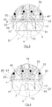
- FIG. 1 illustrates a cross sectional view of an electropneumatic solenoid valve according to an exemplary embodiment of the present disclosure.
- FIG. 2 illustrates a cross sectional view of the electropneumatic solenoid valve of FIG. 1 according to an exemplary embodiment in which the electromagnetic control device is deactivated and the biasing means (e.g., spring) pushes the flapper valve member to the opposite side wall including two air channels.
- the biasing means e.g., spring
- FIG. 3 illustrates a cross sectional view of a solenoid valve according to an exemplary embodiment of the present disclosure having an activated electromagnetic control device.
- FIG. 4 illustrates the cross sectional view of the valve of FIG. 3 with the electromagnetic control device being deactivated.
- FIG. 5 illustrates a cross sectional view of the valve of FIGS. 1 and 2 according to an exemplary embodiment with the electromagnetic control device being activated.
- FIG. 6 illustrates the cross sectional view of FIG. 5 with the electromagnetic control device being deactivated.
- an object of the disclosure is to overcome the disadvantages of the related art, in particular, to improve an electropneumatic solenoid valve or magnet valve for a pneumatically actuated field device.
- an object of the disclosure is to provide a precise working function of the electropneumatic magnet valve of simple design even given different operating conditions.
- an electropneumatic solenoid valve or magnet valve is provided for a pneumatically actuated field device, in particular a positioner, position controller or final control device, of a processing plant.
- a processing plant can include, for example, a chemical plant, a petrochemical plant, a food processing plant (e.g., a brewery), a power plant or the like.
- the magnet valve has an air supply channel, in particular, for attachment to a source of pressurized air (e.g., constant 6 bar).
- a controlled air signal from, for example, an electropneumatic position controller can also be attached to the air supply channel.
- the magnet valve has an air dispensing channel for connecting to, for example, a pneumatic positioning drive, which can be of the single-action or a double-action type.
- the magnet valve can additionally comprise an air exhaust channel.
- the magnet valve defines, partially through its housing structure, an air chamber, into which the air channels mound.
- the air chamber is delimited except for the interior housing structure of the magnet valve, also by structures which are to be magnetized, the particularly axial bore surfaces thereof, which may for example be a coil core or coil coat.
- one of the air channels, such as the air exhaust channel is formed within the coil core.
- the electropneumatic magnet valve For releasing and for closing each respective air channel, the electropneumatic magnet valve according to an exemplary embodiment comprises a flapper valve member, such as a magnetisable flapper plate and an electromagnetic control device.
- the flapper plate defines mutually parallel plane plate sides.
- the electromagnetic control device can be configured to displace the flapper valve member in an axial control direction for ventilating and/or exhausting the air dispensing channel.
- the electromagnetic control device is formed by a coil to be supplied with electricity, the coil radially surrounding the coil core of metal, and having, for the formation of a closed magnetic circuit, a coil core radially surrounding the coil.
- the magnet valve has an additional (mechanical) biasing means, such as a pressure spring, and/or a magnetic biasing means configured to urge the flapper valve member in the control direction into a closed position for closing one of the air channels.
- the electromagnetic control device is configured to move the flapper valve member between two operating positions. A closing positions is where on one side the air supply conduit or air dispensing channel and on the other side the air exhaust channel is sealed in an air tight manner by the flapper valve member.
- the flapper valve member has a closure element particularly being arranged on the control direction axis, the closure element coming into engagement for closing one of the air channels in particular with a delimitation mounding edge of the respective air channel such that the flapper valve member is arranged and held in a circumferential axial distance, in particular in a constant circumferential annular distance, towards the axially adjacent delimitation interior wall of the air chamber such that the flapper valve member remains non-displaceable (or stationary) in the radial direction even in case of radial impacts.
- the flapper valve member sealingly engages exclusively with the delimitation mounding edge for providing for a safe and air-tight closing of the air channel. A further contact to the delimitation interior wall is excluded by the circumferential axial distance.
- the circumferential axial distance occurs when the flapper valve member is arranged in a perpendicular or orthogonal orientation relative to the control direction axis.
- the flapper valve member is dimensioned in relation to the mounding edge of the air channel to be closed such that an involuntary orientation of the flapper valve member is caused during its movement into the closing position in particular under the influence of the electromagnetic forces and/or of the biasing means.
- the air channel to be closed and the mounding edge thereof in the air chamber delimitation wall are realized as a valve seat bore.
- the flapper valve member, the seat bore, in particular opposing seat bores, and in particular, an axial maximal stroke of the flapper valve member in the air chamber are dimensioned/realized such that the flapper valve member is held, in particular, in the area of the seat bores, through the delimitation edge of the housing structure, a core structure of the electromagnetic control device and upon operation, and closing particularly involuntarily centres itself centrally in the seat bore.
- the bore edges of the seat bore form the holding structure against which the flapper valve member meets in order to be held in the radial direction.
- the flapper valve member in another dimensioning of the valve system, it may, due to the float-mounted mounting of the flapper valve member, the flapper valve member may come into an axial contact with the delimitation interior wall of the air chamber in an angled position relative to the control direction axis. This may go along with an exceptional operating condition, such as an impact load onto the magnet valve, which may be only at a small area of contact which, however, does not impair the air tight sealing of the air channel.
- an exceptional operating condition such as an impact load onto the magnet valve
- the flapper plate can be dimensioned and structured relative to the particular plane delimitation interior wall of the air chambers such that a constant circumferential distance in the axial direction towards the delimitation interior wall is set when the plate-shaped flapper valve member is oriented in a desired or vertical orientation relative to the direction axial of the electromagnetic control device.
- the flapper plate is arranged in the air chamber such that a radial contact of the flapper plate to the delimitation wall of the air chamber is avoided.
- a radial contact is to be avoided insofar as an increased amount of friction, which would go along with such a contact, would be negative in view of the functional operation.
- the radial distance between the flapper plate and the delimitation wall of the air chamber is to be chosen (e.g., to be dimensioned) such that no (or little) radial touch or engagement can occur during normal operation of the operator.
- the magnetic flapper plate can be float-mounted for normal operation such that, in the opening condition thereof, the flapper plate exclusively stands in an engaging contact with the biasing means (e.g., spring), and in the closed condition thereof, the flapper plate exclusively stands in an engaging contact on one side with the biasing means and on the other side with a valve seat or the like.
- the biasing means e.g., spring
- the flapper valve member e.g., the magnetic flapper plate
- the flapper valve member is arranged in the air chamber without any further guiding means such that a contact of the flapper valve member with the delimitation wall sections of the air chamber exclusively occurs in the centering area of the flapper valve member.
- contacts of the flapper member, in particular of the flapper plate shall be excluded.
- the omission of any further guidance means, such as guiding pins results in a significant reduction of assembly work, wherein it has surprisingly been shown that the operability of the float-mounted flapper valve is not impaired.
- the closure element is formed as a protrusion that projects on both sided from the plane flapper valve member.
- the protrusion is at least partially convex spherically shaped.
- the closure element is arranged/formed in the axial center of an in particular circular flapper plate of the flapper valve member.
- the closing element is formed as a circular ball mounted separately in the flapper plate and/or made of a non-magnetic material such as ceramics. In an exemplary embodiment, the separately mounted ball consists exclusively of the non-magnetic material.
- the flapper valve member has a radially inner interior stop section diametrically opposite from the coil core of the electromagnetic control device, and an outer end stop section radially outward surrounding the inner end stop section and the outer end stop section lying diametrically opposite to a coil coat of the electromagnetic control device radially outwardly surrounding the coil of the electromagnetic control device or diametrically opposite to a housing section of the magnet valve.
- the outer end stop section does not necessarily need to serve the function of stopping or touching, however, should the float-mounting of the flapper plate, for instance due to a momentarily tilted position in the case of assembly or due to an impact load, be moved away from its usual displacement-position and -direction, an extraordinary outward stop or inward stop is made possible to provide for a short term tilting with limited tilting amplitude. It is the cooperation of the electromagnetic force of the electromagnetic control device and/or of the biasing means in relation to the embodiment of the closure element of the flapper valve member in conjunction with the mounding edge of the channel to be closed, which provides for the alignment/holding of the flapper plate for forming the contact-free axial distance to the delimitation wall.
- one of the air channels such as the air exhaust channel, is formed in the coil core.
- the air channel in the coil core with which the closure section shall cooperate in a tightly sealing manner, it is of advantage that non-magnetic material is provided for the closure element.
- the flapper plate and the corresponding end stop sections are configured, structured and/or dimensioned such that, during sealing occupation of the air channel in the coil core by the closure element of the flapper valve member, the radially outer axial distance of the flapper valve member to the outer end stop section is smaller than the inner axial distance of the flapper valve member to the inner end stop section.
- the radially inner axial distance is, during occupation of the air channel with the coil core by the closure element, smaller than, for example, 0.5 mm, 0.3 mm or 0.1 mm, but is not limited thereto.
- the radially outer axial distance is at least one third or at least one half smaller than the radially inner axial distance. This way, it is ascertained that the tilting amplitude of the float-mounted flapper valve member is limited particularly through the outwardly lying end stop.
- a further air channel such as an air supply channel or air dispensing channel
- the further air channel can be inserted such that the backside of the closure element, the front side of which closes the air channel in the coil core, upon corresponding axial displacement of the flapper valve member under influence of the biasing mean, closes the air channel in the magnet valve housing wall.
- the further air channel can be formed radially offset to the air channel in the magnet valve housing wall, such as the air dispensing channel or air supply channel, which in particular is not closeable by the flapper valve member in any axial control position thereof. The radially offset air channel is in no axial control position of the flapper valve member closeable by the flapper valve member.
- the air chamber is radially limited by an essentially cylindrical chamber interior wall which is at least partially formed by the magnet valve housing.
- the air chamber can be axially limited by an adjacent housing wall in which at least two air channels are inserted and which lies opposite from the magnetisable component of the electromagnetic control device.
- this magnetic structure of the electromagnetic control device which limits the air chamber on the opposite axial side.
- the annular flapper plate of the flapper valve member in particular being of constant flapper plate thickness, can be float-mounted axially movable and in particular like a piston.
- the flapper valve member is exclusively mechanically guided by the biasing means.
- the axial, maximal movement amplitude of the flapper valve member in the axial control direction is as most one tenth to one quarter of the particularly constant axial strength of the flapper plate (the thickness of the flapper plate can lie between, for example, 0.6 mm and 1 mm and the stroke between 0.1 mm and 0.3 mm). In this way, a good air exchange between the two air chamber compartments separated by the flapper valve is provided.
- the flapper plate serves to close each individual air channel and moves axially between the axially opposite limitation walls of the air chamber in which the in particular axially opposite air channels are arranged.
- the axial, particularly maximal, amplitude of movement of the flapper valve member in the axial direction is at least 1/10, at least 1 ⁇ 8, or at least 1 ⁇ 4 of the cross sectional diameter of the nozzle diameter and/or at most 9/10, at most 2 ⁇ 3, at most 1 ⁇ 2 of the nozzle diameter.
- the stroke i.e. the amplitude of movement, amounts to between 0.1 mm and 1.5 mm or between 0.2 mm and 0.6 mm.
- the stroke is 0.4 mm. The present disclosure is not limited to these example values.
- the thickness of the flapper plate (cross section) has a thickness such that even in case of a maximum supply of the magnet core with electric current; the flapper plate does not achieve the magnetic saturation.
- the flapper plate has a thickness of less than 2 mm, or less than 1 mm.
- the flapper plate has a thickness less than 0.5 mm, but is not limited thereto. These thickness keep the mass of the flapper plate small.
- the flapper valve member for arrangement within an air chamber of an electropneumatic solenoid valve or magnet valve is described herein.
- the flapper valve member includes a flapper plate and possibly the aforementioned closure element.
- the flapper plate has an axial closure side, and in some embodiments, two diametrically opposite axial closure sides, which are to face at least one air channel to be closed or to be released.
- the closure side(s) can at least surface-sectionally come into engagement contact with an axial contact wall of the air chamber to be magnetised by the electromagnetic control device of the magnet valve.
- the at least one air channel can be formed.
- the at least one closure outside e.g., both axially diametrically arranged closures outside
- the at least one closure outside is at least surface-sectionally provided with a non-magnetizable material such as, for example, Teflon.
- the surface is provided with a non-magnetizable cover layer, such as a Teflon layer.
- the stickage-avoidance-effect is thus realized by means of a material which is not magnetizable (e.g., cannot be magnetized, or such magnetization is minimal) and provided on the outer contact side of the flapper plate.
- the flapper plate can per se remain magnetizable.
- a non-magnetizable material may form the outside of the flapper plate, whereas at least a core area remains magnetizable and/or magnetizable particles are contained within non-magnetisable materials.
- the electromagnetic solenoid valve is generally designated with reference numeral 1 .
- the electropneumatic solenoid valve 1 comprises a housing 3 with a lid 5 attached to the housing 3 .
- two air channels are inserted into the housing structure, namely an air dispensing channel 11 and an air supply channel 13 .
- Adjacent to the lid 5 a further air channel is worked into the housing structure 3 and indicated with reference numeral 15 .
- This air channel is the air exhaust channel 15 which mounds uninhibited at the outside of the housing 3 .
- the three air channels 11 , 13 , 15 are pneumatically connected to an air chamber 17 , which is at least in part limited by an inner wall section of the housing 3 .
- the air space 17 is cylindrical and additionally limited by a magnetic insert structure of an electromagnetic control device 21 to be detailed below.
- a plate-shaped flapper valve member 23 is movably float-mounted in a piston-like arrangement.
- the flapper valve member 23 comprises a plane flapper plate 25 of a magnetic (e.g., a magnetic soft material).
- the flapper plate 25 can comprises two plane plate surfaces, orthogonal to which the axial control direction S is arranged along which the electromagnetic control device 21 positions the flapper valve member 23 .
- the air supply channel 13 runs coaxially to the axial control direction S wherein the path of the air dispensing channel 11 in the attachment section 7 of the housing 3 also extends in the axial control direction S, however being arranged radially offset with respect to the air supply channel 13 . As indicated above, both air channels 11 , 13 mound into the air chamber 17 .
- an orifice is provided into which a ball-shaped or spherical closure element 31 of a non-magnetic material such as ceramics is inserted and fastened (e.g., pressed in).
- the spherical closure element 31 protrudes on both plate surfaces 27 , 29 in the axial direction; on one side 27 on the radial height of the supply channel 13 , facing same, and on the other side 29 on radial height of the mounding area of the air exhaust channel 15 , the exhaust channel being inserted into a coil core 33 of the electromagnetic control device 21 .
- the semi- or partially spherical protruding closure elements which project from the plane flapper plate 25 are dimensioned such that they can engage essentially air-tight in the corresponding end stop position in the mounding area of the respective air channel 13 , 15 , in order to prevent the venting of the electropneumatic solenoid valve 1 on the one hand (closed air exhaust channel 15 ) and on the other hand in order to avoid any further supply of pressurized pneumatic air from a source (not shown) of pressurized air via the supply line 13 .
- the axial maximal stroke H of the flapper valve member 23 is limited by the axial delimitation walls such that the opposingly projecting closure elements avoid any contact of the flapper plate 25 and the housing, because the respective closure element comes into engaging contact with the mounding edge of the respective air channels 13 or 15 first.
- An axial escape out of the contacting sphere of the mounding edge is excluded in all axial positions of the closure element which is in particular realized through the partially spherical shape of the closure element.
- the electromagnetic control device 21 (also referred to as an electromagnetic controller) comprises a coil 37 which surrounds the coil core 33 in circumferential direction.
- the coil 37 is attached to an electric operator source (e.g., via a control- or positioning-device) and receives electrical control signals to magnetically operate the magnetizable flapper plate 25 of the flapper valve member 23 .
- FIG. 1 the state of attraction is shown in which the coil 37 is activated and can be reached over the magnetic closure on the flapper valve member side-section of the magnetized coil core 33 and the coil coat 39 outwardly surrounding the coil 37 .
- the inactive coil 37 is shown and the flapper valve member 23 is, due to the biasing means (e.g., spring), pushing against the mounding edge of the supply channel 13 to sealingly close it ( FIG. 2 ).
- the flapper valve member 23 is float-mounted within the air chambers 17 such that the only forces acting upon the flapper valve member 23 are the selectively applied electromagnetic force of the control device (when activated), and the constant compression spring force of the spring 41 and the gravitation of the flapper valve member itself (depending upon the orientation of the solenoid valve relative to the directional gravity). In an exemplary embodiment, additional guiding for axially displacing the flapper valve member 23 in the axial control direction S is not necessary.
- the flapper valve member is stationarily arranged in the respective end position (closing the air supply line of the supply channel 13 /closure of the air exhaust channel 15 ) because the spherical closure element 33 self-centeringly fits itself into the mounding channel of the respective air channel.
- no further guidance is provided in order to axially position the control flapper valve member 23 within the air chamber.
- an electromagnetic field is electromagnetically formed/generated to operate the flapper valve 23 depending upon the destination of the electromagnetic control device.
- the solenoid valve in particular the axial movability of the flapper valve member, can easily be examined via an operation control mechanism, which may particularly be realized by an additional permanent magnet 55 which can be brought (e.g., pivoted) from a storage position into an examination position.
- the permanent magnet 55 is configured to bring the magnetizable components of the electromagnetic device into a magnetic field and to examine whether the flapper valve member 23 is thereby caused to be axially positioned.
- supplying the electromagnet control device 21 with electrical energy is not necessary for the functional examination due to the additional application of the permanent magnet 55 .
- the storage position of the permanent magnet 55 is shown in FIG. 1 .
- the active examination condition is not shown in further detail in the figures.
- the permanent magnet 55 is arranged in the axial direction adjacently (above) relative to the electromagnetic control device 22 .
- the permanent magnet 55 in the passive position ( FIG. 1 ), it may be arranged opposite to a soft magnetic fixation element 57 so that the permanent magnet 55 is held in position under the influence of its magnetic force. In order to pivot the permanent magnet 55 into the active position which is not shown in detail, the holding forces must be overcome. In the examination position, in which the permanent magnet 55 is “activated or switched active,” the permanent magnet 55 lies diametrically on the opposite side of the flapper plate 25 and acts upon it magnetically without mechanical contact. Thereby, it can be visually examined whether the flapper plate 25 , depending on the position of the permanent magnet 55 , closes the respective air channel 13 , 15 .
- a circumferential axial slot a, b exists between the front face side 45 , 47 of the coil core 23 or the coil coat 43 , respectively, and an inner end stop plate section 49 or an outer end stop plate section 53 , respectively.
- the end stop plate sections 49 , 53 are not necessarily end stops occurring during normal operation, since the float-mounting is well balanced due to the prevailing forces, so that an engagement or touching is also adapted in view of the design of the closure element 41 and the respective corresponding sections of the air channels 13 , 15 , such that an end stop is not considered.
- an extraordinary load such as an impact load
- a stopping engagement towards one of the plate sections occurs.
- This circumferential slot exists whenever the plate 25 of the flapper valve member 23 is arranged perpendicular relative to the control direction axis S.
- the circumferential axial distance a which is constant in the entire circumferential direction, is slightly smaller than the axial distance b from the flapper plate 25 relative to the head surface 45 of the coil 33 .
- the axial slot a ⁇ (smaller than or equal) half of the axial distance b.
- the axial distance a shall not be formed larger than 0.1 mm, 0.2 mm, 0.3 mm or 1 mm.
- the air supply channel 13 is opened such that the air dispensing channel 11 is exerted to the pressure prevailing in the supply channel 13 .
- the electromagnetic control device 21 is activated such that the electromagnetic attraction force from the coil core 33 , the coil 37 , and the coil coat 43 are larger than the pressure forces of the biasing springs 41 .
- the biasing spring takes over the operation of the flapper valve member 23 and pushes the latter against the inside of the attachment wall section 7 of the housing 3 whereby the proximal spherical closure element 31 engages against the mounding or mouth of the supply channel 13 in an air tight manner.
- the air supply via the air channel 13 is prevented and the dispensing channel 11 is pneumatically connected to the exhaust channel 15 whereby the electropneumatic solenoid valve 1 is exhausted.
- an additional guiding pin 51 is attached to the attachment section 7 and protrudes in the air chamber 17 .
- This guiding pin 51 serves predominantly not for guiding the flapper valve member 23 during normal operation moving the flapper valve member to and from the axial control direction S. Rather, by utilizing the pin, an axial guide 51 shall be provided such that the radial position of the flapper valve member is secured in order to avoid a faulty arrangement of a flapper valve member 23 , in case of impulse-like overload-movements onto the solenoid valve, for example during transport or mounting is avoided.
- these guiding pins 51 can be omitted, even when the radial distance r between the circular and annular outer end of the plate 25 of the flapper plate member 23 and the opposing cylindrical inner wall side of the housing 3 of the air chamber 17 allows only a slight radial movement.
- the present disclosure is not limited to singular pin configurations, and multiple pins could also be provided without providing a guiding function.
- the pins can preferably be dispensed with.
- a radial distance or slot r is smaller than 2 mm. In an exemplary embodiment, the radial distance or slot r is less than, for example, 1 mm, 0.5 mm or 0.2 mm, but is not limited thereto.
- the flapper valve member 23 shown in the figures is made of a magnetic soft material (e.g. metal), including, for example, ferrite, to easier receive attraction forces through the electromagnetic control device.
- a magnetic soft material e.g. metal
- metallic flapper valve members in particular flapper plates 25 , that even in case of de-energizing the coil 37 of the electromagnetic control device 21 , residual magnetic forces act, which cause an adhesion of the flapper valve member 25 to the metal components of the non-electrified control device.
- the magnetic flapper valve member may be provided with a coating of a non-magnetic material, such as Teflon, which avoids such as adhesion.
- the flapper plate 25 can also be realized by a non-metallic material, such as a polymer material and/or plastic material, which may be provided with metallic particles for receiving attraction forces.
- a non-magnetic coating can be omitted in one or more embodiments.
- the air chamber is realized more or less as a cylindrical slot with an axial depth a bit more.
- the axial depth can be, for example, threefold or fourfold smaller than the fivefold of the axial strength of the plate 25 of the flapper valve member 23 . In this way, also wedging of the float-mounted flapper valve member 23 is impaired, particularly during mounting and transporting.
- the radial stops inside of the housing 3 and the axial end stops (e.g. the coil coat 43 and the coil core 33 ), the face sides thereof, as well as the opposite radially extending interior wall sections, do not serve for guiding the flapper valve member.
- the solenoid valve according to the disclosure can be utilized for operation in a position controller and in combination with pneumatic actuators which may be single or double action.
- references in the specification to “one embodiment,” “an embodiment,” “an exemplary embodiment,” etc., indicate that the embodiment described may include a particular feature, structure, or characteristic, but every embodiment may not necessarily include the particular feature, structure, or characteristic. Moreover, such phrases are not necessarily referring to the same embodiment. Further, when a particular feature, structure, or characteristic is described in connection with an embodiment, it is submitted that it is within the knowledge of one skilled in the art to affect such feature, structure, or characteristic in connection with other embodiments whether or not explicitly described.
Abstract
Description
- 1 pneumatic solenoid valve
- 3 housing
- 5 lid
- 7 attachment wall section
- 11 air dispensing channel
- 13 air supply channel
- 15 air exhaust channel
- 17 air space
- 21 electromagnetic control device (or electromagnetic controller)
- 23 plate-shaped flapper valve member
- 25 flapper plate
- 27, 29 plate surfaces
- 31 closure element
- 33 coil core
- 37 coil
- 41 spring
- 43 coil coat
- 45, 47 face area
- 49 inner end stop plate section
- 51 guiding pin
- 53 outer end stop plate section
- 55 permanent magnet
- 57 fixing element
- S axial control direction
- a axial slot
- b axial space
- H movement amplitude/maximum stroke
Claims (15)
Applications Claiming Priority (3)
| Application Number | Priority Date | Filing Date | Title |
|---|---|---|---|
| DE102016106410.6 | 2016-04-07 | ||
| DE102016106410.6A DE102016106410A1 (en) | 2016-04-07 | 2016-04-07 | Electropneumatic solenoid valve, impact valve member for an electropneumatic solenoid valve |
| DE102016106410 | 2016-04-07 |
Publications (2)
| Publication Number | Publication Date |
|---|---|
| US20170292627A1 US20170292627A1 (en) | 2017-10-12 |
| US10724651B2 true US10724651B2 (en) | 2020-07-28 |
Family
ID=58536762
Family Applications (1)
| Application Number | Title | Priority Date | Filing Date |
|---|---|---|---|
| US15/482,127 Active US10724651B2 (en) | 2016-04-07 | 2017-04-07 | Electropneumatic magnet valve, flapper valve member for an electropneumatic magnet valve |
Country Status (4)
| Country | Link |
|---|---|
| US (1) | US10724651B2 (en) |
| EP (1) | EP3228908B1 (en) |
| CN (1) | CN207261672U (en) |
| DE (1) | DE102016106410A1 (en) |
Families Citing this family (4)
| Publication number | Priority date | Publication date | Assignee | Title |
|---|---|---|---|---|
| DE102017106297B4 (en) | 2017-03-23 | 2023-01-19 | Samson Aktiengesellschaft | Electromagnetic flapper assembly |
| DE102018123166B3 (en) * | 2018-09-20 | 2020-03-12 | Samson Aktiengesellschaft | Electric-pneumatic converter |
| DE202023102904U1 (en) | 2023-05-25 | 2023-06-09 | Samson Aktiengesellschaft | Pressure relief solenoid valve and system for a pneumatically operated field device |
| DE202023102911U1 (en) | 2023-05-25 | 2023-06-06 | Samson Aktiengesellschaft | Solenoid valve with swiveling valve plate |
Citations (14)
| Publication number | Priority date | Publication date | Assignee | Title |
|---|---|---|---|---|
| US3921670A (en) * | 1974-07-01 | 1975-11-25 | Clippard Instr Lab Inc | Magnetically operated valve with spider armature |
| US4196751A (en) * | 1976-01-15 | 1980-04-08 | Johnson Controls, Inc. | Electric to fluid signal valve unit |
| US4336823A (en) * | 1979-03-17 | 1982-06-29 | Festo-Maschinenfabrik Gottlieb Stoll | Solenoid valve |
| US4705073A (en) * | 1986-04-23 | 1987-11-10 | Advanced Medical Devices, Inc. | Molded plastic gate valve and sealing means therefor |
| DE9017107U1 (en) | 1990-12-19 | 1992-04-16 | Robert Bosch Gmbh, 7000 Stuttgart, De | |
| US5617894A (en) * | 1994-08-11 | 1997-04-08 | Robert Bosch Gmbh | Valve body |
| DE19636207A1 (en) | 1996-09-06 | 1998-03-12 | Samson Ag | Electrical-fluidic signals converter |
| US20020079007A1 (en) * | 2000-12-21 | 2002-06-27 | Entwistle Richard Thomas | Solenoid valve |
| US20020135451A1 (en) | 2001-03-20 | 2002-09-26 | Dieter Frank | Method for manufacturing a magnet armature |
| US20040261850A1 (en) | 2003-06-26 | 2004-12-30 | Maula Jarmo Ilmari | Diaphragm valve for high-temperature precursor supply in atomic layer deposition |
| US20050115618A1 (en) | 2003-12-01 | 2005-06-02 | Kumar Viraraghavan S. | Co-axial solenoid actuator |
| DE112004001147T5 (en) | 2003-06-26 | 2006-06-29 | Planar Systems, Inc., Beaverton | Diaphragm valve for the deposition of atomic layers |
| US8684036B1 (en) * | 2013-03-07 | 2014-04-01 | Yozo Satoda | Cryogenic valve |
| US8690118B2 (en) * | 2010-01-08 | 2014-04-08 | Caterpillar Inc. | Solenoid actuated device and methods |
Family Cites Families (4)
| Publication number | Priority date | Publication date | Assignee | Title |
|---|---|---|---|---|
| DE4243179C2 (en) * | 1992-12-19 | 2001-08-16 | Bosch Gmbh Robert | Solenoid valve |
| DE19901090A1 (en) * | 1999-01-14 | 2000-07-20 | Bosch Gmbh Robert | Valve for the metered introduction of volatilized fuel |
| DE10340941A1 (en) * | 2003-09-05 | 2005-03-31 | Robert Bosch Gmbh | magnetic valve |
| DE102009038103A1 (en) * | 2009-08-19 | 2011-02-24 | Moeller Gmbh | Electromagnet assembly for hydraulic gate, is provided with fixed, magnetic yoke and anchor, where plastic layers are placed between one of pole faces of magnetic yoke and pole surfaces of anchor |
-
2016
- 2016-04-07 DE DE102016106410.6A patent/DE102016106410A1/en active Pending
-
2017
- 2017-04-06 EP EP17165153.2A patent/EP3228908B1/en active Active
- 2017-04-07 CN CN201720358194.1U patent/CN207261672U/en active Active
- 2017-04-07 US US15/482,127 patent/US10724651B2/en active Active
Patent Citations (15)
| Publication number | Priority date | Publication date | Assignee | Title |
|---|---|---|---|---|
| US3921670A (en) * | 1974-07-01 | 1975-11-25 | Clippard Instr Lab Inc | Magnetically operated valve with spider armature |
| US4196751A (en) * | 1976-01-15 | 1980-04-08 | Johnson Controls, Inc. | Electric to fluid signal valve unit |
| US4336823A (en) * | 1979-03-17 | 1982-06-29 | Festo-Maschinenfabrik Gottlieb Stoll | Solenoid valve |
| US4705073A (en) * | 1986-04-23 | 1987-11-10 | Advanced Medical Devices, Inc. | Molded plastic gate valve and sealing means therefor |
| DE9017107U1 (en) | 1990-12-19 | 1992-04-16 | Robert Bosch Gmbh, 7000 Stuttgart, De | |
| US5617894A (en) * | 1994-08-11 | 1997-04-08 | Robert Bosch Gmbh | Valve body |
| DE19636207A1 (en) | 1996-09-06 | 1998-03-12 | Samson Ag | Electrical-fluidic signals converter |
| US20020079007A1 (en) * | 2000-12-21 | 2002-06-27 | Entwistle Richard Thomas | Solenoid valve |
| US20020135451A1 (en) | 2001-03-20 | 2002-09-26 | Dieter Frank | Method for manufacturing a magnet armature |
| DE10113316A1 (en) | 2001-03-20 | 2002-09-26 | Wabco Gmbh & Co Ohg | Manufacturing process for magnetic armatures |
| US20040261850A1 (en) | 2003-06-26 | 2004-12-30 | Maula Jarmo Ilmari | Diaphragm valve for high-temperature precursor supply in atomic layer deposition |
| DE112004001147T5 (en) | 2003-06-26 | 2006-06-29 | Planar Systems, Inc., Beaverton | Diaphragm valve for the deposition of atomic layers |
| US20050115618A1 (en) | 2003-12-01 | 2005-06-02 | Kumar Viraraghavan S. | Co-axial solenoid actuator |
| US8690118B2 (en) * | 2010-01-08 | 2014-04-08 | Caterpillar Inc. | Solenoid actuated device and methods |
| US8684036B1 (en) * | 2013-03-07 | 2014-04-01 | Yozo Satoda | Cryogenic valve |
Also Published As
| Publication number | Publication date |
|---|---|
| EP3228908A1 (en) | 2017-10-11 |
| US20170292627A1 (en) | 2017-10-12 |
| CN207261672U (en) | 2018-04-20 |
| DE102016106410A1 (en) | 2017-10-12 |
| EP3228908B1 (en) | 2020-06-24 |
Similar Documents
| Publication | Publication Date | Title |
|---|---|---|
| US10724651B2 (en) | Electropneumatic magnet valve, flapper valve member for an electropneumatic magnet valve | |
| US11821539B2 (en) | Gas solenoid valve | |
| US3817488A (en) | Electro-pneumatic device | |
| US7404541B2 (en) | Solenoid valve | |
| US5441233A (en) | Electromagnetic valve | |
| JP2006097900A (en) | Control valve for pressurized fluid, control valve assembly, and function control method of control valve assembly | |
| US8579250B1 (en) | High precision energy efficient valve | |
| KR20000029421A (en) | Solenoid valve | |
| KR101035101B1 (en) | Two-stage air-control valve | |
| EP1959178A3 (en) | Electromagnetically operated valve | |
| US10746318B2 (en) | Electromagnetic impact valve arrangement | |
| US10041598B2 (en) | Coaxially designed, pressure-compensated, directly controlled valve with low pressure losses | |
| US10767665B2 (en) | Pneumatic valve arrangement | |
| US5918856A (en) | Electropneumatic valve | |
| CN110036227B (en) | Valve device | |
| US11754197B2 (en) | Gas solenoid valve | |
| US10234051B2 (en) | Electropneumatic magnet valve | |
| CN112236608B (en) | Valve for fluids, preferably gases | |
| US11885431B2 (en) | Valve module, valve device, valve system | |
| KR102413544B1 (en) | magnet chuck | |
| KR101547950B1 (en) | High speed response solenoid valve | |
| JP2012067875A (en) | Detent-type 3-position electromagnetic selector valve | |
| JP2017150635A (en) | Valve device | |
| JP2019168036A (en) | Valve device | |
| CN203500624U (en) | Non-contact two-way solenoid valve |
Legal Events
| Date | Code | Title | Description |
|---|---|---|---|
| AS | Assignment |
Owner name: SAMSON AKTIENGESELLSCHAFT, GERMANY Free format text: ASSIGNMENT OF ASSIGNORS INTEREST;ASSIGNORS:KOLBENSCHLAG, STEFAN, MR.;PITTELKOW, MICHAEL, MR.;REEL/FRAME:042089/0292 Effective date: 20170411 |
|
| STPP | Information on status: patent application and granting procedure in general |
Free format text: FINAL REJECTION MAILED |
|
| STPP | Information on status: patent application and granting procedure in general |
Free format text: RESPONSE AFTER FINAL ACTION FORWARDED TO EXAMINER |
|
| STPP | Information on status: patent application and granting procedure in general |
Free format text: ADVISORY ACTION MAILED |
|
| STPP | Information on status: patent application and granting procedure in general |
Free format text: DOCKETED NEW CASE - READY FOR EXAMINATION |
|
| STPP | Information on status: patent application and granting procedure in general |
Free format text: NON FINAL ACTION MAILED |
|
| STPP | Information on status: patent application and granting procedure in general |
Free format text: RESPONSE TO NON-FINAL OFFICE ACTION ENTERED AND FORWARDED TO EXAMINER |
|
| STPP | Information on status: patent application and granting procedure in general |
Free format text: FINAL REJECTION MAILED |
|
| STPP | Information on status: patent application and granting procedure in general |
Free format text: RESPONSE AFTER FINAL ACTION FORWARDED TO EXAMINER |
|
| STPP | Information on status: patent application and granting procedure in general |
Free format text: ADVISORY ACTION MAILED |
|
| STPP | Information on status: patent application and granting procedure in general |
Free format text: NOTICE OF ALLOWANCE MAILED -- APPLICATION RECEIVED IN OFFICE OF PUBLICATIONS |
|
| STPP | Information on status: patent application and granting procedure in general |
Free format text: PUBLICATIONS -- ISSUE FEE PAYMENT VERIFIED |
|
| STCF | Information on status: patent grant |
Free format text: PATENTED CASE |
|
| MAFP | Maintenance fee payment |
Free format text: PAYMENT OF MAINTENANCE FEE, 4TH YEAR, LARGE ENTITY (ORIGINAL EVENT CODE: M1551); ENTITY STATUS OF PATENT OWNER: LARGE ENTITY Year of fee payment: 4 |