EP2080942B1 - Dispositif de ventilation doté d'un dispositif de fixation à aimant permanent - Google Patents
Dispositif de ventilation doté d'un dispositif de fixation à aimant permanent Download PDFInfo
- Publication number
- EP2080942B1 EP2080942B1 EP08020780A EP08020780A EP2080942B1 EP 2080942 B1 EP2080942 B1 EP 2080942B1 EP 08020780 A EP08020780 A EP 08020780A EP 08020780 A EP08020780 A EP 08020780A EP 2080942 B1 EP2080942 B1 EP 2080942B1
- Authority
- EP
- European Patent Office
- Prior art keywords
- valve
- axial
- radial
- holding surface
- unit according
- Prior art date
- Legal status (The legal status is an assumption and is not a legal conclusion. Google has not performed a legal analysis and makes no representation as to the accuracy of the status listed.)
- Not-in-force
Links
Images


Classifications
-
- F—MECHANICAL ENGINEERING; LIGHTING; HEATING; WEAPONS; BLASTING
- F16—ENGINEERING ELEMENTS AND UNITS; GENERAL MEASURES FOR PRODUCING AND MAINTAINING EFFECTIVE FUNCTIONING OF MACHINES OR INSTALLATIONS; THERMAL INSULATION IN GENERAL
- F16K—VALVES; TAPS; COCKS; ACTUATING-FLOATS; DEVICES FOR VENTING OR AERATING
- F16K31/00—Actuating devices; Operating means; Releasing devices
- F16K31/12—Actuating devices; Operating means; Releasing devices actuated by fluid
- F16K31/122—Actuating devices; Operating means; Releasing devices actuated by fluid the fluid acting on a piston
-
- F—MECHANICAL ENGINEERING; LIGHTING; HEATING; WEAPONS; BLASTING
- F16—ENGINEERING ELEMENTS AND UNITS; GENERAL MEASURES FOR PRODUCING AND MAINTAINING EFFECTIVE FUNCTIONING OF MACHINES OR INSTALLATIONS; THERMAL INSULATION IN GENERAL
- F16K—VALVES; TAPS; COCKS; ACTUATING-FLOATS; DEVICES FOR VENTING OR AERATING
- F16K11/00—Multiple-way valves, e.g. mixing valves; Pipe fittings incorporating such valves
- F16K11/02—Multiple-way valves, e.g. mixing valves; Pipe fittings incorporating such valves with all movable sealing faces moving as one unit
- F16K11/04—Multiple-way valves, e.g. mixing valves; Pipe fittings incorporating such valves with all movable sealing faces moving as one unit comprising only lift valves
- F16K11/044—Multiple-way valves, e.g. mixing valves; Pipe fittings incorporating such valves with all movable sealing faces moving as one unit comprising only lift valves with movable valve members positioned between valve seats
-
- F—MECHANICAL ENGINEERING; LIGHTING; HEATING; WEAPONS; BLASTING
- F16—ENGINEERING ELEMENTS AND UNITS; GENERAL MEASURES FOR PRODUCING AND MAINTAINING EFFECTIVE FUNCTIONING OF MACHINES OR INSTALLATIONS; THERMAL INSULATION IN GENERAL
- F16K—VALVES; TAPS; COCKS; ACTUATING-FLOATS; DEVICES FOR VENTING OR AERATING
- F16K31/00—Actuating devices; Operating means; Releasing devices
- F16K31/02—Actuating devices; Operating means; Releasing devices electric; magnetic
- F16K31/06—Actuating devices; Operating means; Releasing devices electric; magnetic using a magnet, e.g. diaphragm valves, cutting off by means of a liquid
- F16K31/08—Actuating devices; Operating means; Releasing devices electric; magnetic using a magnet, e.g. diaphragm valves, cutting off by means of a liquid using a permanent magnet
- F16K31/084—Actuating devices; Operating means; Releasing devices electric; magnetic using a magnet, e.g. diaphragm valves, cutting off by means of a liquid using a permanent magnet the magnet being used only as a holding element to maintain the valve in a specific position, e.g. check valves
-
- F—MECHANICAL ENGINEERING; LIGHTING; HEATING; WEAPONS; BLASTING
- F16—ENGINEERING ELEMENTS AND UNITS; GENERAL MEASURES FOR PRODUCING AND MAINTAINING EFFECTIVE FUNCTIONING OF MACHINES OR INSTALLATIONS; THERMAL INSULATION IN GENERAL
- F16K—VALVES; TAPS; COCKS; ACTUATING-FLOATS; DEVICES FOR VENTING OR AERATING
- F16K31/00—Actuating devices; Operating means; Releasing devices
- F16K31/12—Actuating devices; Operating means; Releasing devices actuated by fluid
- F16K31/42—Actuating devices; Operating means; Releasing devices actuated by fluid by means of electrically-actuated members in the supply or discharge conduits of the fluid motor
- F16K31/423—Actuating devices; Operating means; Releasing devices actuated by fluid by means of electrically-actuated members in the supply or discharge conduits of the fluid motor the actuated members consisting of multiple way valves
Definitions
- the invention relates to a valve device, with a in a receiving chamber of a valve housing axially movably arranged valve spool which is switchable by Fluidbeaufschlagung between two stop means predetermined end positions and is releasably retained in at least one of these end positions by a holding means by magnetic forces generated by at least one permanent magnet, wherein the holding device has axially facing first and second axial holding surfaces, of which the first axial holding surface is fixedly arranged on an end portion of the receiving chamber on the valve housing and the opposite second axial holding surface on the valve spool so that first axial magnetic forces can form between the two axial holding surfaces , which hold the valve spool in the end position.
- Pulse valves are multi-way valves whose valve spool for switching between two end positions are impulsively acted upon by means of a fluidic control pressure, wherein the valve spool retains the end position even after the removal of the control pressure. So that the valve spool remains in the end position even with vibrations, is the two End portions of the receiving chamber each associated with a holding device.
- the holding device contains a permanent magnet and causes a releasable retention of the valve spool by means of axial magnetic forces.
- the axial magnetic forces are formed between a valve housing arranged on the first axial support surface and one of these opposite, arranged on the valve spool second axial support surface.
- the first axial holding surface is located on a permanent magnet arranged on the valve housing.
- stop means are provided between the two axial holding surfaces, which predetermine the end position of the valve slide such that a direct contact between the two axial holding surfaces is prevented.
- Such direct contact would result in high mechanical loads when reaching the end position.
- arise in direct contact very high axial magnetic forces that are difficult to overcome by the applied to switch the valve spool control pressure.
- a problem with the known valve device are the tolerances that occur during manufacture and assembly. These can cause the axial distance which the axial holding surfaces have in the end position of the valve slide to vary in size. This effect would be even more pronounced if the stop means were not located directly between the two axial retaining surfaces. The consequence of a varying axial distance between the axial holding surfaces are different high axial magnetic forces, which are effective in the end position. Thus, it may happen that with a plurality of valve devices of the same design different high fluid forces are required to the valve spool from one end position to the other end position switch. As a result, switching times of different lengths can occur, which makes the mutual coordination of several jointly used valve devices more difficult.
- each valve device must be operated with the maximum control pressure, which can still overcome the axial magnetic forces with certainty even when the worst case tolerance case exists.
- a valve spool which is held with only small axial magnetic forces, experiences a high acceleration, so that high loads occur on impact in the other end position.
- the holding device in addition to the first and second axial holding surface, in the end position of the valve slide radially with respect to the longitudinal axis of the receiving chamber opposite first and second radial holding surfaces, of which the first radial holding surface fixed to the valve housing and the second radial holding surface is arranged on the valve slide, such that form the second axial magnetic forces opposite the first axial magnetic forces between the two radial holding surfaces, when the second radial holding surface projects axially beyond the first radial holding surface.
- the second axial magnetic force correspondingly increases and acts increasingly more strongly against the likewise increasing first axial magnetic force , In this way, independent of manufacturing tolerances, relatively uniform magnetic holding force can be ensured in the end position of the valve spool.
- valve device can in particular be designed as a so-called seat valve, in which the valve slide has at least one closure body which cooperates with an axially oriented valve seat, these components forming the stop means.
- poppet valves is the End position of the valve spool to a particular extent tolerance-dependent, because the closure body is usually in the cooperating with the valve seat area of an elastic material that is yielding to some extent.
- the valve device may be equipped with only one holding device in order to fix the valve spool in only one end position by means of magnetic force.
- a configuration in which two holding devices are present is particularly expedient, so that both end positions can be fixed by permanent-magnetic forces. There is then a bistable valve device.
- the stop means should be designed such that in the end position of the valve slide there is an axial air gap between the axial holding surfaces facing each other.
- the radial retaining surfaces are annular, so that they surround coaxially in the end position with a radial distance.
- These are in particular circular cylindrical surfaces.
- the retaining surfaces could also be subdivided into a plurality of surface sections which are around the Longitudinal axis of the receiving chamber are distributed around.
- a symmetrical distribution is advantageous here, so that the resulting radial magnetic forces exert no resulting transverse forces on the valve spool.
- the rear end edge of the first radial holding surface which points axially away from the valve slide, is expediently placed in front of a plane which contains the first axial holding face arranged on the valve housing.
- the second axial holding surface is located on an end face of the valve spool. It may in particular be formed on a holding body, which consists of a permanent magnetic or of a ferromagnetic material. At the same time, the holding body can serve to fasten a drive piston present for applying fluid to the valve slide to a main body of the valve slide.
- a particularly advantageous structural design provides that the first radial support surface is supported by a support projection which protrudes in a radially outwardly of the first axial support surface area in front of a plane which is perpendicular to the longitudinal axis of the receiving chamber and contains the first axial support surface.
- the support projection is preferably formed annular.
- the responsible for the generation of the permanent magnetic magnetic forces at least one permanent magnet is preferably arranged on the valve housing. He is suitably enclosed by a ferromagnetic yoke body having the support projection. Preferably, the yoke body is cup-shaped, wherein it receives the permanent magnet in itself.
- the yoke body rests on the rear end portion of the permanent magnet.
- the rear end portion of the permanent magnet is the end portion facing away from the valve spool.
- the yoke body extends beyond the outside at a radial distance, so that there is a radial air gap between the yoke body and the permanent magnet in this area. Following this air gap, the yoke body is bent or angled radially inward and carries at its end the first radial holding surface.
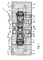
- FIG. 1 shows in a longitudinal section the entirety of a valve device 1 according to the invention, which may be referred to as a bistable valve or as a pulse valve.
- the valve device 1 contains a main valve 2 that can be actuated by fluid power and two pilot control valves 3a, 3b that control its fluid supply and that are electrically actuatable.
- the valve device 1 has a valve housing 4, which consists in the embodiment of a central part 5 and two on opposite end faces attached thereto outer parts 6a, 6b.
- the outer parts 6a, 6b each contain one of the only indicated by dashed lines pilot valves 3a, 3b.
- an elongated receiving chamber 7 extends. It expediently passes through the central part 5 and is closed at both ends by the outer parts 6a, 6b.
- valve housing 4 In the receiving chamber 7 open laterally, at axially spaced locations, a plurality of the valve housing 4 passing through valve channels 8 a. Inside the receiving chamber 7 is a to the receiving chamber 7 coaxial, elongated valve spool 12 which is movable in the axial direction of the longitudinal axis 13 of the receiving chamber 7. In this way, the valve spool 12 between a in FIG. 1 shown first end position and an opposite second end position are switched.
- the switching movement 14 is indicated by a double arrow.
- valve channels 8 are connected to each other in a known manner in a different pattern.
- a to a pressure source connected feed channel 8a alternately connected to one of two leading to a consumer working channels 8b, 8c.
- the working channel 8b, 8c not connected to the feed duct 8a is in communication with one of two exhaust ducts 8d, 8e leading to the atmosphere.
- the valve device 1 of the embodiment is of the type of a poppet valve. Between those sections of the receiving chamber 7 into which the valve channels 8 open, annular valve seats 15 are arranged on the valve housing 4. They are axially oriented and surround the valve spool 12 coaxially with a radial distance. Thus remains between each valve seat 15 and the valve spool 12 an annular gap, which allows a passage of fluid.
- Each valve seat 15 is located on the valve spool 12 arranged closure body 16 axially opposite. Depending on the end position, the closure body 16 may rest on the adjacent valve seat 15 or be lifted off the valve seat 15 in order to prevent or permit fluid to pass through the above-mentioned annular gap.
- the koorper Schlierenden valve seats 15 and closure body 16 simultaneously form stop means 17 which define the two disfigurements of the valve spool 12, that is, in the two end positions between the valve spool 12 and the valve housing 4 assumed axial relative position.
- the switching movement 14 of the valve slide 12 is caused by the fact that arranged on the two end faces of the valve spool 12 drive surfaces 18 are acted upon by a control fluid through the two pilot valves 3a, 3b can be supplied controlled.
- Each drive surface 18 delimits a drive space 22 defined by the associated end section of the receiving chamber 7, into which a pilot control channel 23 connected to one of the pilot control valves 3a, 3b opens.
- Each pilot valve 3a, 3b is also connected via a pilot feed passage 24 to a pilot feed port 25 of the valve housing 4, through which the control fluid is fed.
- each pilot valve 3a, 3b has a discharge opening 26 connected to the atmosphere.
- the control fluid may alternatively be tapped from the feed duct 8a when the pilot feed ducts 24 are connected to this feed duct 18a.
- pilot valves 3a, 3b By electrical actuation signals, which are supplied to the pilot valves 3a, 3b via electrical interface means 27 from an electronic control device, not shown, the pilot valves 3a, 3b can be actuated such that builds up in the associated drive chamber 22 either the switching to the other end position effecting control pressure or the drive chamber 22 is depressurized.
- valve spool 12 is also held securely in its two end positions when both drive chambers 22 are depressurized, each end portion of the receiving chamber 7 is assigned a valve spool 12 in the associated end position by means of magnetic force releasably retaining holding device 28. Since the two holding devices 28 are identical, the further description is limited to the in FIG. 1 Left illustrated holding device 28, which serves to fix the valve spool 12 in the second end position.
- the FIGS. 2 to 8 each refer to this aforementioned left holding device 28th
- the said magnetic forces are generated by at least one permanent magnet 31 and are thus independent of electrical energy.
- the fluid forces exerted by the fire fluid are greater than the magnetic holding forces, so the latter can be overcome to switch the valve spool 12.
- the holding device 28 includes first and second axial holding surfaces 32, 33, the one another in the axial direction of the longitudinal axis 13, that is, axially opposite, wherein they face each other.
- the first axial holding surface 32 is arranged fixedly on the valve housing 4 in the region of the end section of the receiving chamber 7.
- a different width of the axial gap 34 defined between the two axial retaining surfaces 32, 33 results. Under “width "Here are the dimensions in the axial direction of the longitudinal axis 13 to understand.
- the width of the axial gap 34 of the responsible for holding the second end position holding device 28 is a maximum. This is off FIG. 2 seen.
- the minimum width of the axial gap 34 is present when the valve spool 12 occupies the fixable by this holding device 28 second end position ( FIG. 8 ).
- first axial magnetic forces 35 can form, bias the valve spool 12 in the end position and hold in the final position. These first axial magnetic forces 35 are greater, the smaller the width of the axial gap 34 is. In the state of the maximum width of the axial gap 34 according to FIG. 2 are the first axial magnetic forces 35 a minimum or possibly, due to the large distance of the axial support surfaces 32, 33, not present at all.
- the "axial” direction means the axial direction of the longitudinal axis 13 and the "radial direction” the direction transverse to this longitudinal axis 13.
- the second axial holding surface 33 is formed in the embodiment on a front side on the valve spool 12 arranged holding body 37.
- the holding body 37 is designed in particular plate-shaped or disk-shaped. It consists of a ferromagnetic material, but can in principle also consist of a permanent magnetic material.
- the holding body 37 is arranged coaxially to the longitudinal axis 13, wherein its outer peripheral surface forms a second radial holding surface 43 of the holding device 28. This is shaped in particular circular cylindrical.
- the valve spool 12 expediently contains a rod-shaped or bar-shaped main body 44 which carries the closure body 16. On both end faces, a drive piston 45, which defines the drive surface 18, is attached to the base body 44. By means of a fastening element 38, which upstream of the drive piston 45 axially outside is and which is bolted to the base body 44, the drive piston 45 is fixed to the base body 44.
- the second axial holding surface 33 is expediently located on the end face of the abovementioned permanent magnet 31 which axially faces the valve slide 12.
- the permanent magnet 31 is preferably circular-cylindrical and has an axial polarization. It is accommodated in a cup-shaped yoke body 46, which consists of a ferromagnetic material.
- the yoke body 46 is fixed to the valve housing 4. It is oriented so that its opening 37 faces the valve spool 12 and its bottom wall 48 bears against the rear end face 52 of the permanent magnet 31 opposite the first axial holding surface 32. Conveniently, the permanent magnet 31 is glued to the yoke body 46.
- the yoke body 46 is expediently likewise adhesively bonded to the valve housing 4, but may also be fixed by other fastening measures.
- the permanent magnet is flanked by the side wall 53 of the yoke body 46 surrounding it.
- the side wall 53 protrudes axially in the direction of the valve spool 12, wherein it protrudes toward the valve spool 12 via a plane 54 which is perpendicular to the longitudinal axis 13 and contains the first holding surface 32.
- the aforementioned level 54 is referred to below as “reference level 54" for better distinction.
- annular support projection 55 which carries a first radial support surface 42 of the holding device 28. While the above-mentioned second radial support surface 43 faces radially outward, the first radial support surface 42 is oriented radially inward.
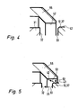
- the radial distance from the longitudinal axis 13 to the second radial support surface 43 is less than to the first radial support surface 42. In this way, it is possible that the second radial support surface 43 immersed in the bounded by the first radial support surface 42 area when the valve spool 12 approaches the second end position. This is off FIG. 5 clearly visible.
- the two radial retaining surfaces 42, 43 are radially opposite with respect to the longitudinal axis 13 and jointly define an annular air gap 56.
- the first radial holding surface 42 is preferably circular-cylindrical. Their radial distance from the longitudinal axis 13 is greater than the radial distance between this longitudinal axis 13 and the radially outer end edge 57 of the first axial support surface 32.
- the two axial support surfaces 32, 33 expediently have the same outline, so that the distance of the second radial support surface 43rd from the longitudinal axis 13 corresponds to the radial distance between the end edge 57 and the longitudinal axis 13.
- the first radial holding surface 42 is formed and arranged so that its rear end edge 58 of the reference plane 54, which is axially remote from the valve slide, is arranged at a distance in front of the valve slide 12 at a distance. This means that between the two axial support surfaces 32, 33 and then an axial gap 34 remains when the second radial support surface 43 overlaps so far in the axial direction with the first radial support surface 42, that its front end edge 59 with the rear end edge 58 of the first radial support surface 42 is at the same axial height. This condition is off FIG. 7 seen.
- the axial gap 34 is expediently a void and can therefore be referred to as an air gap. This is possible because the above-mentioned stop means 17 are arranged outside this axial gap 34.
- the stop means 17 are formed so that the two axial support surfaces 32, 33 do not touch in the end position of the valve spool 12, but an air gap remains. This is important because a direct contact between the two axial support surfaces 32, 33 would result in very high magnetic forces, which would hinder or prevent the switching of the valve spool 12.
- the existing in the end position between the two axial support surfaces 32, 33 intermediate space 34 always has the same measured width in the axial direction.
- the distance between the two axial holding surfaces 32, 33 vary due to tolerances.
- the particular configuration of the holding means 28 now ensures that regardless of variations in the width of the gap 34 which the valve spool 12 in the end position holding axial magnetic forces are relatively uniform and then do not increase excessively when the width of the intermediate space 34 is relatively small.
- FIGS. 4, 5 . 7 and 8 explain. Here are shown states that occur when the valve spool 12 moves from the first end position to the second end position.
- magnetic forces 63 which have an axial force component which coincides with the direction of force of the gradually increasing first axial magnetic forces 35 are provided obliquely in the direction of the end position.
- the second radial holding surface 43 displaces more and more axially beyond the terminating edge 58 of the first radial holding surface 42. As a result, the second radial holding surface 43 projects beyond the first radial holding surface 42 in the axial direction facing away from the valve slide 12.
- the significant effect of this is that between the first radial support surface 42 and the above the first radial support surface 42 projecting longitudinal portion of the second radial support surface 43 an obliquely radially outward and at the same time axially to the valve spool 12 oriented magnetic force sets 64, one opposite to the the first axial magnetic forces 35 acting axial force component includes, which is hereinafter referred to as the second axial magnetic force 36.
- the radial magnetic forces 62 that form between the overlapping portions of the two radial support surfaces 42, 43 are irrelevant.
- the strength of the second axial magnetic forces 36 depends on the axial relative position between the two radial retaining surfaces 42, 43, and in particular also how far the second radial retaining surface 43 axially over the housing-first first radial support surface 42 toward the first axial support surface 32 protrudes.
- the tolerances can be coordinated so that, for example, the two in FIGS. 7 and 8 shown states define the maximum possible and the minimum possible width of the axial gap 34. So these are the tolerance limits.
- the forces acting on the valve spool 12 in the axial direction magnetic holding forces remain relative constant, because with increasing reduction of the existing between the two holding surfaces 32, 33 distance, the then increasing first axial magnetic forces 35 counteracting second axial magnetic forces 36 also increase.
- the described effect can be realized not only with annular self-contained radial holding surfaces 42, 43.
- the radial retaining surfaces 42, 43 could also be subdivided into individual surface sections distributed around the longitudinal axis 13. A symmetrical distribution is sought here, so that the radial magnetic forces 62 compensate and exert no undesirable transverse forces on the valve spool 12.
- the side wall 53 is formed in the region of the front end portion of the permanent magnet 31 so as to be at a radial distance at the outer circumferential surface of the permanent magnet 31 extends past, over the reference plane 54 addition.
- the side wall 53 is bent or angled radially inward to form the support projection 55 and ends with the first radial holding surface 42nd
Landscapes
- Engineering & Computer Science (AREA)
- General Engineering & Computer Science (AREA)
- Mechanical Engineering (AREA)
- Magnetically Actuated Valves (AREA)
Claims (20)
- Dispositif à soupape avec un tiroir de soupape (12) disposé de manière axialement mobile dans une chambre de réception (7) d'une cage de soupape (4), qui peut être commuté par sollicitation fluidique entre deux positions finales prescrites par des moyens de butée (17) et est maintenu de manière détachable dans au moins l'une de ces positions finales par un dispositif de retenue (28) à l'aide de forces magnétiques générées par au moins un aimant permanent (31), le dispositif de retenue (28) présentant des premières et secondes surfaces de retenue (32, 33) axiales, tournées axialement l'une vers l'autre, dont la première surface de retenue axiale (32) est fixement disposée sur une section d'extrémité de la chambre de réception (7) sur la cage de soupape (4) et la seconde surface de retenue axiale opposée (33) sur le tiroir de soupape (12) de sorte qu'entre les deux surfaces de retenue (32, 33) axiales puissent se réaliser des premières forces magnétiques (35) axiales qui maintiennent le tiroir de soupape (12) dans la position finale, caractérisé en ce que le dispositif de retenue (28) présente outre les premières et les secondes surfaces de retenue axiales (32, 33), des premières et secondes surfaces de retenue (42, 43) radiales opposées dans la position finale du tiroir de soupape (12) radialement par rapport à l'axe longitudinal (13) de la chambre de réception (7), dont la première surface de retenue radiale (42) est fixement disposée sur la cage de soupape (4) et la seconde surface de retenue (43) radiale sur le tiroir de soupape (12) de telle sorte qu'entre les deux surfaces de retenue radiales (42, 43) se réalisent des secondes forces magnétiques axiales (36) opposées aux premières forces magnétiques (35) axiales lorsque la seconde surface de retenue radiale (43) dépasse axialement de la première surface de retenue (42) radiale.
- Dispositif à soupape selon la revendication 1, caractérisé en ce que deux dispositifs de retenue (28) associés respectivement à l'une des deux zones d'extrémité de la chambre de réception (7) sont présents pour la fixation détachable des deux positions finales du tiroir de soupape (12).
- Dispositif à soupape selon la revendication 1 ou 2, caractérisé en ce que les moyens de butée (17) prescrivant la position finale sont disposés en dehors de l'espace intermédiaire (34) axial défini entre la première et la seconde surface de retenue (32, 33) axiale.
- Dispositif à soupape selon la revendication 3, caractérisé en ce que les moyens de butée (17) sont formés par au moins un siège de soupape (15) orienté axialement, disposé fixement sur la cage de soupape (4) et un corps de fermeture (16) disposé sur le tiroir de soupape (12), coopérant avec ce siège de soupape (15).
- Dispositif à soupape selon l'une quelconque des revendications 1 à 4, caractérisé en ce que les deux surfaces de retenue (32, 33) axiales peuvent être espacées en fonction des tolérances de manière différente axialement l'une par rapport à l'autre dans la position finale du tiroir de soupape (12), la seconde surface de retenue (43) radiale s'élevant en fonction de cette distance axiale de manière différente au-delà de la première surface de retenue radiale (42).
- Dispositif à soupape selon l'une quelconque des revendications 1 à 5, caractérisé en ce que les moyens de butée (17) sont réalisés de sorte que dans la position finale du tiroir de soupape (12) se trouve un entrefer axial entre les deux surfaces de retenue axiales (32, 33).
- Dispositif à soupape selon l'une quelconque des revendications 1 à 6, caractérisé en ce que la première surface de retenue radiale (42) est tournée radialement vers l'intérieur et la seconde surface de retenue radiale (43) vers l'extérieur.
- Dispositif à soupape selon l'une quelconque des revendications 1 à 7, caractérisé en ce que les surfaces de retenue radiales (42, 43) sont réalisées en forme d'anneau et s'entourent coaxialement dans la position finale du tiroir de soupape (12) à distance radiale.
- Dispositif à soupape selon l'une quelconque des revendications 1 à 8, caractérisé en ce que l'arête de fermeture (58) côté arrière éloignée axialement du tiroir de soupape (12) de la première surface de retenue (42) radiale est montée à distance en amont d'un plan (54) contenant la première surface de retenue axiale (32) vers le tiroir de soupape (12).
- Dispositif à soupape selon l'une quelconque des revendications 1 à 9, caractérisé en ce que la première surface de retenue radiale (42) est disposée à une distance radiale plus grande par rapport à l'axe longitudinal (13) de la chambre de réception (7) que l'arête de fermeture (57) se trouvant radialement à l'extérieur de la première surface de retenue axiale (32).
- Dispositif à soupape selon l'une quelconque des revendications 1 à 10, caractérisé en ce que la seconde surface de retenue axiale (33) est réalisée sur un corps de retenue (37) disposé côté avant sur le tiroir de soupape (12), qui se compose d'un matériau ferromagnétique ou magnétique permanent.
- Dispositif à soupape selon la revendication 11, caractérisé en ce que le corps de retenue (37) est formé par un élément de fixation (38) qui est vissé à un corps de base (44) du tiroir de soupape (12) afin de fixer un piston d'entraînement (45) servant à la sollicitation fluidique.
- Dispositif à soupape selon la revendication 11 ou 12, caractérisé en ce que la seconde surface de retenue (43) radiale est disposée sur la périphérie extérieure du corps de retenue (37).
- Dispositif à soupape selon l'une quelconque des revendications 1 à 13, caractérisé en ce que la première surface de retenue radiale (42) est réalisée sur une saillie porteuse (55) qui s'élève radialement en dehors de la première surface de retenue axiale (32) en direction du tiroir de soupape (12) avant un plan (54) à angles droits par rapport à l'axe longitudinal (13) de la chambre de réception (7), contenant la première surface de retenue axiale (32).
- Dispositif à soupape selon la revendication 14, caractérisé en ce que la saillie porteuse (55) est courbée ou coudée radialement vers l'intérieur, vu en section, vers la première surface de retenue (42) radiale.
- Dispositif à soupape selon la revendication 14 ou 15, caractérisé en ce que la saillie porteuse (55) est réalisée en forme d'anneau et est disposée coaxialement à l'axe longitudinal (13) de la chambre de réception (7).
- Dispositif à soupape selon l'une quelconque des revendications 14 à 16, caractérisé en ce que la saillie porteuse (55) est un constituant d'un corps de culasse (46) ferromagnétique qui entoure un aimant permanent (31) présentant la première surface de retenue axiale (32).
- Dispositif à soupape selon la revendication 17, caractérisé en ce que le corps de culasse (46) est réalisé en forme de pot et reçoit l'aimant permanent (31).
- Dispositif à soupape selon la revendication 17 ou 18, caractérisé en ce que le corps de culasse (46) repose sur la section finale de l'aimant permanent (31) arrière, opposée au tiroir de soupape (12), alors qu'il saisit en passant la section finale avant de l'aimant permanent (31) à distance radiale et est ensuite courbé ou coudé radialement vers l'intérieur.
- Dispositif à soupape selon l'une quelconque des revendications 1 à 19, caractérisé en ce qu'il est réalisé comme une soupape à impulsions.
Applications Claiming Priority (1)
| Application Number | Priority Date | Filing Date | Title |
|---|---|---|---|
| CN2008100046122A CN101493153B (zh) | 2008-01-21 | 2008-01-21 | 包括永久磁性保持装置的阀装置 |
Publications (3)
| Publication Number | Publication Date |
|---|---|
| EP2080942A2 EP2080942A2 (fr) | 2009-07-22 |
| EP2080942A3 EP2080942A3 (fr) | 2009-10-14 |
| EP2080942B1 true EP2080942B1 (fr) | 2010-08-25 |
Family
ID=40456703
Family Applications (1)
| Application Number | Title | Priority Date | Filing Date |
|---|---|---|---|
| EP08020780A Not-in-force EP2080942B1 (fr) | 2008-01-21 | 2008-11-29 | Dispositif de ventilation doté d'un dispositif de fixation à aimant permanent |
Country Status (4)
| Country | Link |
|---|---|
| EP (1) | EP2080942B1 (fr) |
| CN (1) | CN101493153B (fr) |
| AT (1) | ATE479037T1 (fr) |
| DE (1) | DE502008001197D1 (fr) |
Cited By (1)
| Publication number | Priority date | Publication date | Assignee | Title |
|---|---|---|---|---|
| DE102015216766B3 (de) * | 2015-09-02 | 2017-01-12 | Festo Ag & Co. Kg | Antriebsvorrichtung |
Families Citing this family (4)
| Publication number | Priority date | Publication date | Assignee | Title |
|---|---|---|---|---|
| ATE491108T1 (de) * | 2009-03-10 | 2010-12-15 | Festo Ag & Co Kg | Ventileinrichtung |
| EP3236123A1 (fr) * | 2016-04-19 | 2017-10-25 | Primetals Technologies Austria GmbH | Dispositif d'actionnement pour un piston de commande d'une soupape hydraulique |
| CN106618202A (zh) * | 2016-12-30 | 2017-05-10 | 温州益兴机电科技有限公司 | 一种桶盖、饮水机 |
| CN107701210B (zh) * | 2017-10-24 | 2019-09-03 | 北京天地玛珂电液控制系统有限公司 | 一种基于永磁驱动式的液控单向阀控制机构 |
Family Cites Families (5)
| Publication number | Priority date | Publication date | Assignee | Title |
|---|---|---|---|---|
| US3304126A (en) * | 1965-02-15 | 1967-02-14 | Gorman Rupp Co | Material handling apparatus and methods |
| DE2729482A1 (de) * | 1977-06-30 | 1979-01-11 | Herion Werke Kg | Mehrwege-umschaltventil |
| DE3900718A1 (de) * | 1989-01-12 | 1990-07-26 | Depa Ges Fuer Verfahrenstechni | Verfahren und vorrichtung zur steuerung einer druckluftbetriebenen doppelmembranpumpe |
| CN2603254Y (zh) * | 2003-03-12 | 2004-02-11 | 北京威力清矿山控制技术有限公司 | 液控截止阀 |
| ATE380959T1 (de) * | 2005-08-31 | 2007-12-15 | Festo Ag & Co | Vorgesteuertes impulsventil |
-
2008
- 2008-01-21 CN CN2008100046122A patent/CN101493153B/zh not_active Expired - Fee Related
- 2008-11-29 AT AT08020780T patent/ATE479037T1/de active
- 2008-11-29 EP EP08020780A patent/EP2080942B1/fr not_active Not-in-force
- 2008-11-29 DE DE502008001197T patent/DE502008001197D1/de active Active
Cited By (1)
| Publication number | Priority date | Publication date | Assignee | Title |
|---|---|---|---|---|
| DE102015216766B3 (de) * | 2015-09-02 | 2017-01-12 | Festo Ag & Co. Kg | Antriebsvorrichtung |
Also Published As
| Publication number | Publication date |
|---|---|
| CN101493153A (zh) | 2009-07-29 |
| DE502008001197D1 (de) | 2010-10-07 |
| CN101493153B (zh) | 2010-09-29 |
| EP2080942A3 (fr) | 2009-10-14 |
| EP2080942A2 (fr) | 2009-07-22 |
| ATE479037T1 (de) | 2010-09-15 |
Similar Documents
| Publication | Publication Date | Title |
|---|---|---|
| DE602005003421T2 (de) | Pneumatisches Ventil | |
| EP1760376B1 (fr) | Vanne à impulsion servo-commandée | |
| DE102014112110B4 (de) | Fünf-Wege-Schaltventil mit Restdruckablassventil | |
| EP1748238B1 (fr) | Soupape électromagnétique | |
| EP0681128A1 (fr) | Electrovanne | |
| EP3464968B1 (fr) | Dispositif soupape électromagnétique et système | |
| EP2080942B1 (fr) | Dispositif de ventilation doté d'un dispositif de fixation à aimant permanent | |
| DE102012003175A1 (de) | Magnetventil | |
| DE102012001842B4 (de) | Magnetventil | |
| EP3067598B1 (fr) | Vanne multi-voies | |
| EP1508732B1 (fr) | Dispositif de soupape | |
| EP2871394A1 (fr) | Système de vannes | |
| EP2228576B1 (fr) | Dispositif de soupape | |
| DE102011108522B4 (de) | Mehrwegeventil und Verfahren zu dessen Betreiben | |
| EP2110591B1 (fr) | Soupape | |
| EP1345483A2 (fr) | Dispositif de contact pour actionneur de soupape et ensemble soupape ainsi équipé | |
| EP3698383A1 (fr) | Dispositif actionneur électromagnétique et son utilisation | |
| DE102008005834A1 (de) | Ventileinrichtung mit Handhilfsbetätigungseinrichtung | |
| EP0687818A1 (fr) | Valve pneumatique | |
| DE102004037269B3 (de) | Elektropneumatisches Ventil mit pneumatisch betätigtem Steuerkolben | |
| EP2994675B1 (fr) | Vanne | |
| DE102006035568B4 (de) | Arbeitsvorrichtung | |
| EP3146245B1 (fr) | Vanne à plusieurs voies | |
| DE102013016548B3 (de) | Beweglicher Anker eines Magnetventils und damit ausgestattetes Magnetventil | |
| EP2994674B1 (fr) | Vanne |
Legal Events
| Date | Code | Title | Description |
|---|---|---|---|
| PUAI | Public reference made under article 153(3) epc to a published international application that has entered the european phase |
Free format text: ORIGINAL CODE: 0009012 |
|
| AK | Designated contracting states |
Kind code of ref document: A2 Designated state(s): AT BE BG CH CY CZ DE DK EE ES FI FR GB GR HR HU IE IS IT LI LT LU LV MC MT NL NO PL PT RO SE SI SK TR |
|
| AX | Request for extension of the european patent |
Extension state: AL BA MK RS |
|
| PUAL | Search report despatched |
Free format text: ORIGINAL CODE: 0009013 |
|
| AK | Designated contracting states |
Kind code of ref document: A3 Designated state(s): AT BE BG CH CY CZ DE DK EE ES FI FR GB GR HR HU IE IS IT LI LT LU LV MC MT NL NO PL PT RO SE SI SK TR |
|
| AX | Request for extension of the european patent |
Extension state: AL BA MK RS |
|
| 17P | Request for examination filed |
Effective date: 20091106 |
|
| GRAP | Despatch of communication of intention to grant a patent |
Free format text: ORIGINAL CODE: EPIDOSNIGR1 |
|
| AKX | Designation fees paid |
Designated state(s): AT BE BG CH CY CZ DE DK EE ES FI FR GB GR HR HU IE IS IT LI LT LU LV MC MT NL NO PL PT RO SE SI SK TR |
|
| GRAS | Grant fee paid |
Free format text: ORIGINAL CODE: EPIDOSNIGR3 |
|
| GRAA | (expected) grant |
Free format text: ORIGINAL CODE: 0009210 |
|
| AK | Designated contracting states |
Kind code of ref document: B1 Designated state(s): AT BE BG CH CY CZ DE DK EE ES FI FR GB GR HR HU IE IS IT LI LT LU LV MC MT NL NO PL PT RO SE SI SK TR |
|
| REG | Reference to a national code |
Ref country code: GB Ref legal event code: FG4D Free format text: NOT ENGLISH |
|
| REG | Reference to a national code |
Ref country code: CH Ref legal event code: EP |
|
| REG | Reference to a national code |
Ref country code: IE Ref legal event code: FG4D Free format text: LANGUAGE OF EP DOCUMENT: GERMAN |
|
| REF | Corresponds to: |
Ref document number: 502008001197 Country of ref document: DE Date of ref document: 20101007 Kind code of ref document: P |
|
| REG | Reference to a national code |
Ref country code: NL Ref legal event code: VDEP Effective date: 20100825 |
|
| LTIE | Lt: invalidation of european patent or patent extension |
Effective date: 20100825 |
|
| PG25 | Lapsed in a contracting state [announced via postgrant information from national office to epo] |
Ref country code: LT Free format text: LAPSE BECAUSE OF FAILURE TO SUBMIT A TRANSLATION OF THE DESCRIPTION OR TO PAY THE FEE WITHIN THE PRESCRIBED TIME-LIMIT Effective date: 20100825 Ref country code: FI Free format text: LAPSE BECAUSE OF FAILURE TO SUBMIT A TRANSLATION OF THE DESCRIPTION OR TO PAY THE FEE WITHIN THE PRESCRIBED TIME-LIMIT Effective date: 20100825 Ref country code: NO Free format text: LAPSE BECAUSE OF FAILURE TO SUBMIT A TRANSLATION OF THE DESCRIPTION OR TO PAY THE FEE WITHIN THE PRESCRIBED TIME-LIMIT Effective date: 20101125 |
|
| PG25 | Lapsed in a contracting state [announced via postgrant information from national office to epo] |
Ref country code: CY Free format text: LAPSE BECAUSE OF FAILURE TO SUBMIT A TRANSLATION OF THE DESCRIPTION OR TO PAY THE FEE WITHIN THE PRESCRIBED TIME-LIMIT Effective date: 20100825 Ref country code: BG Free format text: LAPSE BECAUSE OF FAILURE TO SUBMIT A TRANSLATION OF THE DESCRIPTION OR TO PAY THE FEE WITHIN THE PRESCRIBED TIME-LIMIT Effective date: 20101125 Ref country code: HR Free format text: LAPSE BECAUSE OF FAILURE TO SUBMIT A TRANSLATION OF THE DESCRIPTION OR TO PAY THE FEE WITHIN THE PRESCRIBED TIME-LIMIT Effective date: 20100825 Ref country code: IS Free format text: LAPSE BECAUSE OF FAILURE TO SUBMIT A TRANSLATION OF THE DESCRIPTION OR TO PAY THE FEE WITHIN THE PRESCRIBED TIME-LIMIT Effective date: 20101225 Ref country code: PL Free format text: LAPSE BECAUSE OF FAILURE TO SUBMIT A TRANSLATION OF THE DESCRIPTION OR TO PAY THE FEE WITHIN THE PRESCRIBED TIME-LIMIT Effective date: 20100825 Ref country code: SI Free format text: LAPSE BECAUSE OF FAILURE TO SUBMIT A TRANSLATION OF THE DESCRIPTION OR TO PAY THE FEE WITHIN THE PRESCRIBED TIME-LIMIT Effective date: 20100825 |
|
| REG | Reference to a national code |
Ref country code: IE Ref legal event code: FD4D |
|
| PG25 | Lapsed in a contracting state [announced via postgrant information from national office to epo] |
Ref country code: NL Free format text: LAPSE BECAUSE OF FAILURE TO SUBMIT A TRANSLATION OF THE DESCRIPTION OR TO PAY THE FEE WITHIN THE PRESCRIBED TIME-LIMIT Effective date: 20100825 Ref country code: GR Free format text: LAPSE BECAUSE OF FAILURE TO SUBMIT A TRANSLATION OF THE DESCRIPTION OR TO PAY THE FEE WITHIN THE PRESCRIBED TIME-LIMIT Effective date: 20101126 Ref country code: SE Free format text: LAPSE BECAUSE OF FAILURE TO SUBMIT A TRANSLATION OF THE DESCRIPTION OR TO PAY THE FEE WITHIN THE PRESCRIBED TIME-LIMIT Effective date: 20100825 Ref country code: LV Free format text: LAPSE BECAUSE OF FAILURE TO SUBMIT A TRANSLATION OF THE DESCRIPTION OR TO PAY THE FEE WITHIN THE PRESCRIBED TIME-LIMIT Effective date: 20100825 |
|
| PG25 | Lapsed in a contracting state [announced via postgrant information from national office to epo] |
Ref country code: DK Free format text: LAPSE BECAUSE OF FAILURE TO SUBMIT A TRANSLATION OF THE DESCRIPTION OR TO PAY THE FEE WITHIN THE PRESCRIBED TIME-LIMIT Effective date: 20100825 Ref country code: IE Free format text: LAPSE BECAUSE OF FAILURE TO SUBMIT A TRANSLATION OF THE DESCRIPTION OR TO PAY THE FEE WITHIN THE PRESCRIBED TIME-LIMIT Effective date: 20100825 |
|
| BERE | Be: lapsed |
Owner name: FESTO A.G. & CO. KG Effective date: 20101130 |
|
| PG25 | Lapsed in a contracting state [announced via postgrant information from national office to epo] |
Ref country code: RO Free format text: LAPSE BECAUSE OF FAILURE TO SUBMIT A TRANSLATION OF THE DESCRIPTION OR TO PAY THE FEE WITHIN THE PRESCRIBED TIME-LIMIT Effective date: 20100825 Ref country code: CZ Free format text: LAPSE BECAUSE OF FAILURE TO SUBMIT A TRANSLATION OF THE DESCRIPTION OR TO PAY THE FEE WITHIN THE PRESCRIBED TIME-LIMIT Effective date: 20100825 Ref country code: SK Free format text: LAPSE BECAUSE OF FAILURE TO SUBMIT A TRANSLATION OF THE DESCRIPTION OR TO PAY THE FEE WITHIN THE PRESCRIBED TIME-LIMIT Effective date: 20100825 Ref country code: EE Free format text: LAPSE BECAUSE OF FAILURE TO SUBMIT A TRANSLATION OF THE DESCRIPTION OR TO PAY THE FEE WITHIN THE PRESCRIBED TIME-LIMIT Effective date: 20100825 |
|
| PG25 | Lapsed in a contracting state [announced via postgrant information from national office to epo] |
Ref country code: ES Free format text: LAPSE BECAUSE OF FAILURE TO SUBMIT A TRANSLATION OF THE DESCRIPTION OR TO PAY THE FEE WITHIN THE PRESCRIBED TIME-LIMIT Effective date: 20101206 Ref country code: MC Free format text: LAPSE BECAUSE OF NON-PAYMENT OF DUE FEES Effective date: 20101130 |
|
| PLBE | No opposition filed within time limit |
Free format text: ORIGINAL CODE: 0009261 |
|
| STAA | Information on the status of an ep patent application or granted ep patent |
Free format text: STATUS: NO OPPOSITION FILED WITHIN TIME LIMIT |
|
| 26N | No opposition filed |
Effective date: 20110526 |
|
| PG25 | Lapsed in a contracting state [announced via postgrant information from national office to epo] |
Ref country code: BE Free format text: LAPSE BECAUSE OF NON-PAYMENT OF DUE FEES Effective date: 20101130 |
|
| REG | Reference to a national code |
Ref country code: DE Ref legal event code: R097 Ref document number: 502008001197 Country of ref document: DE Effective date: 20110526 |
|
| PG25 | Lapsed in a contracting state [announced via postgrant information from national office to epo] |
Ref country code: MT Free format text: LAPSE BECAUSE OF FAILURE TO SUBMIT A TRANSLATION OF THE DESCRIPTION OR TO PAY THE FEE WITHIN THE PRESCRIBED TIME-LIMIT Effective date: 20100825 |
|
| PG25 | Lapsed in a contracting state [announced via postgrant information from national office to epo] |
Ref country code: HU Free format text: LAPSE BECAUSE OF FAILURE TO SUBMIT A TRANSLATION OF THE DESCRIPTION OR TO PAY THE FEE WITHIN THE PRESCRIBED TIME-LIMIT Effective date: 20110226 Ref country code: LU Free format text: LAPSE BECAUSE OF NON-PAYMENT OF DUE FEES Effective date: 20101129 |
|
| PG25 | Lapsed in a contracting state [announced via postgrant information from national office to epo] |
Ref country code: TR Free format text: LAPSE BECAUSE OF FAILURE TO SUBMIT A TRANSLATION OF THE DESCRIPTION OR TO PAY THE FEE WITHIN THE PRESCRIBED TIME-LIMIT Effective date: 20100825 |
|
| REG | Reference to a national code |
Ref country code: CH Ref legal event code: PL |
|
| PG25 | Lapsed in a contracting state [announced via postgrant information from national office to epo] |
Ref country code: LI Free format text: LAPSE BECAUSE OF NON-PAYMENT OF DUE FEES Effective date: 20121130 Ref country code: PT Free format text: LAPSE BECAUSE OF NON-PAYMENT OF DUE FEES Effective date: 20100825 Ref country code: CH Free format text: LAPSE BECAUSE OF NON-PAYMENT OF DUE FEES Effective date: 20121130 |
|
| REG | Reference to a national code |
Ref country code: AT Ref legal event code: MM01 Ref document number: 479037 Country of ref document: AT Kind code of ref document: T Effective date: 20131129 |
|
| PG25 | Lapsed in a contracting state [announced via postgrant information from national office to epo] |
Ref country code: AT Free format text: LAPSE BECAUSE OF NON-PAYMENT OF DUE FEES Effective date: 20131129 |
|
| REG | Reference to a national code |
Ref country code: FR Ref legal event code: PLFP Year of fee payment: 8 |
|
| REG | Reference to a national code |
Ref country code: FR Ref legal event code: PLFP Year of fee payment: 9 |
|
| PGFP | Annual fee paid to national office [announced via postgrant information from national office to epo] |
Ref country code: GB Payment date: 20161109 Year of fee payment: 9 Ref country code: FR Payment date: 20161124 Year of fee payment: 9 |
|
| PGFP | Annual fee paid to national office [announced via postgrant information from national office to epo] |
Ref country code: IT Payment date: 20161129 Year of fee payment: 9 |
|
| GBPC | Gb: european patent ceased through non-payment of renewal fee |
Effective date: 20171129 |
|
| REG | Reference to a national code |
Ref country code: FR Ref legal event code: ST Effective date: 20180731 |
|
| PG25 | Lapsed in a contracting state [announced via postgrant information from national office to epo] |
Ref country code: IT Free format text: LAPSE BECAUSE OF NON-PAYMENT OF DUE FEES Effective date: 20171129 Ref country code: FR Free format text: LAPSE BECAUSE OF NON-PAYMENT OF DUE FEES Effective date: 20171130 |
|
| PG25 | Lapsed in a contracting state [announced via postgrant information from national office to epo] |
Ref country code: GB Free format text: LAPSE BECAUSE OF NON-PAYMENT OF DUE FEES Effective date: 20171129 |
|
| REG | Reference to a national code |
Ref country code: DE Ref legal event code: R082 Ref document number: 502008001197 Country of ref document: DE Representative=s name: PATENTANWAELTE MAGENBAUER & KOLLEGEN PARTNERSC, DE Ref country code: DE Ref legal event code: R081 Ref document number: 502008001197 Country of ref document: DE Owner name: FESTO SE & CO. KG, DE Free format text: FORMER OWNER: FESTO AG & CO. KG, 73734 ESSLINGEN, DE Ref country code: DE Ref legal event code: R081 Ref document number: 502008001197 Country of ref document: DE Owner name: FESTO AG & CO. KG, DE Free format text: FORMER OWNER: FESTO AG & CO. KG, 73734 ESSLINGEN, DE |
|
| PGFP | Annual fee paid to national office [announced via postgrant information from national office to epo] |
Ref country code: DE Payment date: 20201024 Year of fee payment: 13 |
|
| REG | Reference to a national code |
Ref country code: DE Ref legal event code: R119 Ref document number: 502008001197 Country of ref document: DE |
|
| PG25 | Lapsed in a contracting state [announced via postgrant information from national office to epo] |
Ref country code: DE Free format text: LAPSE BECAUSE OF NON-PAYMENT OF DUE FEES Effective date: 20220601 |