EP3228501B1 - Dispositif d'éclairage pour un couvercle extérieur sur un côté d'un véhicule - Google Patents
Dispositif d'éclairage pour un couvercle extérieur sur un côté d'un véhicule Download PDFInfo
- Publication number
- EP3228501B1 EP3228501B1 EP17382116.6A EP17382116A EP3228501B1 EP 3228501 B1 EP3228501 B1 EP 3228501B1 EP 17382116 A EP17382116 A EP 17382116A EP 3228501 B1 EP3228501 B1 EP 3228501B1
- Authority
- EP
- European Patent Office
- Prior art keywords
- light
- film
- arrangement
- photolith
- aperture
- Prior art date
- Legal status (The legal status is an assumption and is not a legal conclusion. Google has not performed a legal analysis and makes no representation as to the accuracy of the status listed.)
- Active
Links
- 230000005540 biological transmission Effects 0.000 claims description 20
- 238000005286 illumination Methods 0.000 claims description 9
- 230000003287 optical effect Effects 0.000 claims description 8
- 239000003973 paint Substances 0.000 claims description 7
- 238000001746 injection moulding Methods 0.000 claims description 3
- 239000000758 substrate Substances 0.000 description 5
- 230000010355 oscillation Effects 0.000 description 4
- 206010015037 epilepsy Diseases 0.000 description 3
- 230000004075 alteration Effects 0.000 description 2
- 230000005672 electromagnetic field Effects 0.000 description 2
- 230000005670 electromagnetic radiation Effects 0.000 description 2
- 230000033001 locomotion Effects 0.000 description 2
- 239000000243 solution Substances 0.000 description 2
- 241000220225 Malus Species 0.000 description 1
- CERQOIWHTDAKMF-UHFFFAOYSA-M Methacrylate Chemical compound CC(=C)C([O-])=O CERQOIWHTDAKMF-UHFFFAOYSA-M 0.000 description 1
- 239000003086 colorant Substances 0.000 description 1
- 230000005684 electric field Effects 0.000 description 1
- 230000005611 electricity Effects 0.000 description 1
- 230000007246 mechanism Effects 0.000 description 1
- 238000000465 moulding Methods 0.000 description 1
- 229920000642 polymer Polymers 0.000 description 1
- 238000011084 recovery Methods 0.000 description 1
Images


Classifications
-
- B—PERFORMING OPERATIONS; TRANSPORTING
- B60—VEHICLES IN GENERAL
- B60Q—ARRANGEMENT OF SIGNALLING OR LIGHTING DEVICES, THE MOUNTING OR SUPPORTING THEREOF OR CIRCUITS THEREFOR, FOR VEHICLES IN GENERAL
- B60Q1/00—Arrangement of optical signalling or lighting devices, the mounting or supporting thereof or circuits therefor
- B60Q1/26—Arrangement of optical signalling or lighting devices, the mounting or supporting thereof or circuits therefor the devices being primarily intended to indicate the vehicle, or parts thereof, or to give signals, to other traffic
- B60Q1/32—Arrangement of optical signalling or lighting devices, the mounting or supporting thereof or circuits therefor the devices being primarily intended to indicate the vehicle, or parts thereof, or to give signals, to other traffic for indicating vehicle sides, e.g. clearance lights
-
- B—PERFORMING OPERATIONS; TRANSPORTING
- B60—VEHICLES IN GENERAL
- B60R—VEHICLES, VEHICLE FITTINGS, OR VEHICLE PARTS, NOT OTHERWISE PROVIDED FOR
- B60R13/00—Elements for body-finishing, identifying, or decorating; Arrangements or adaptations for advertising purposes
-
- G—PHYSICS
- G09—EDUCATION; CRYPTOGRAPHY; DISPLAY; ADVERTISING; SEALS
- G09F—DISPLAYING; ADVERTISING; SIGNS; LABELS OR NAME-PLATES; SEALS
- G09F13/00—Illuminated signs; Luminous advertising
- G09F13/04—Signs, boards or panels, illuminated from behind the insignia
-
- G—PHYSICS
- G09—EDUCATION; CRYPTOGRAPHY; DISPLAY; ADVERTISING; SEALS
- G09F—DISPLAYING; ADVERTISING; SIGNS; LABELS OR NAME-PLATES; SEALS
- G09F21/00—Mobile visual advertising
- G09F21/04—Mobile visual advertising by land vehicles
Definitions
- the present patent application relates to a lighting arrangement comprising an outer cover for a side area of a vehicle according to claim 1.
- the actuating device includes a housing defining a periphery and an interior volume.
- a cover plate is fixedly secured to the housing at the periphery.
- the cover plate defines an inboard surface facing the interior volume and an outboard surface opposite the inboard surface.
- the outboard surface is opaque in standard ambient light conditions.
- the actuating device also includes a switch that is operatively connected to the inboard surface of the cover plate at a defined location for toggling the device between on and off conditions.
- the actuating device also includes a presence sensor identifying when an operator is adjacent to the cover plate. An internal light illuminates the cover plate such that light passes through the cover plate and out the outboard surface to illuminate the switch for the operator.
- This device presents a set of illuminated capacitive actuators for introducing a code for opening the vehicle without a key. It includes LED diodes that emit light in a direction opposite to the direction of projection towards the operator, by filling a light cavity and allowing the light to exit only via an intermediate element with a graphic, located between the sensors and the cover element.
- the cover is tinted black. Note, however, that the generation of light is not optimal: the LEDs emit light in a direction opposite to the direction of projection. The aim is to fill the interior volume with light, resulting in significant loss and inefficiency, leading to low quality in terms of the homogeneity of the projected light, as well as a projected light of low intensity.
- a vehicular trim component with interior and exterior surfaces which comprises: a partially light-transmissive substrate; an adjacent illumination source, the illumination source being actuatable between an illuminated state and a non-illuminated state; and a variably light-transmissive layer on a first surface of the substrate.
- the variably light-transmissive layer includes a non-light-transmissive opaque portion and a light-transmissive portion.
- the light-transmissive portion comprises one or more lines defined through the opaque portion and arranged to define visually perceptible indicia when the illumination source is in the illuminated state. Each line is visually imperceptible to the naked eye when the illumination source is in the non-illuminated state.
- the light of the LED emitter is oriented in the same direction as the direction of projection of the logo, mask or intermediate element with a graphic, allowing light to pass through a transparent zone.
- lighting there are clear differences as regards lighting and the generation of a homogeneous concept of lighting.
- very bright areas just in front of the emitter
- areas not so well lit where there is no emitter directly behind
- Auras and arcs are produced, making it impossible to obtain a homogeneous image.
- an exterior component for a vehicle which includes a first member having a decorative surface provided on an external portion thereof for transmitting light, the first member further including a first engaging portion, a second member having a second engaging portion engaging with the first engaging portion of the first member, the first member and the second member forming a double layered structure. It also includes a light-emitting member. The light is shut off in response to a supply of electricity supplied from the vehicle.
- Figures 3A and 3B show the technical approval requirements for vehicles, according to which there must be no emitter of direct light visible in the following marked areas for a vehicle when running, similar to surface cones, at a distance of 25 m. Therefore, an observer present within the areas marked in Figures 3A and 3B must not see any red light-emitting member (at the front of the vehicle) or white light-emitting member (at the rear of the vehicle) except for those provided for lighting, braking, indicating, etc. Consequently, it is necessary to find a solution that ensures the vehicle complies with the approval requirements while allowing projection of the logo or graphic to be illuminated when said vehicle is running or is in motion.
- a marking display structure for a motor vehicle window arranged to illuminate, from inside, a marking display element so that the marking, which represent the type, model or the like of the motor vehicle, can be recognized not only during day time but also at night.
- a vehicle lighting device comprising at least one light emitter connected to a light transmitting means, a partially translucent upper layer, the light transmitting means being essentially flat and comprising a region having at least one optical structure deviating light towards the upper layer, and an opaque mask having at least one superimposed transparent zone , between the transmitting means and the upper layer, said lighting device comprising a lower reflective layer adjacent the light transmitting means and located on the opposite side of the opaque mask having at least one transparent zone.
- said lighting device is invisible when it is in its off state and has, by design, the ability to emit complex shapes through a surface that, in appearance, is not a luminous element.
- a lighting device for an outer cover on a side of a vehicle in the form of a trim element, in which the light emitted to the exterior is homogeneous, and which complies with the technical approval requirements for the vehicle as regards the projection of light towards the side areas when the vehicle is running.
- the present invention proposes projecting an illuminated logo at any point on the side of the vehicle, preferably the plastic parts of the doors, either front or rear, making the minimum possible alterations to the current structure of said door, by, for example, using an LED emitter that lights up a logo through an opening in the exterior door trim. Consequently, it is not the aim of the present invention to generate a light beam to light up the side area of the vehicle, but to illuminate a logo located on the side of the vehicle so that it can be seen under all kinds of conditions.
- light is transverse electromagnetic radiation, i.e. the oscillation of the electromagnetic field is perpendicular to the propagation thereof.
- the oscillation of the electromagnetic field is perpendicular to the propagation thereof.
- a single direction of oscillation can be filtered, in which state the light is polarized.
- polarized light is light with a predetermined direction of oscillation.
- polarized light There are three types of polarized light: linear, circular and elliptical.
- a polarizing filter may be considered to be a grid that only allows the passage of light that oscillates in the plane parallel to the vector normal to the surface of the grid.
- the light transmitted to the other side of the polarizing element is considered to be polarized light.
- commercial polarizing filters consist of a polymer chain stretched to the limit, so that the molecules act as a grid that strongly absorbs a polarized component of light and is very transparent to the other component, as described by Malus's Law.
- a polarizing element comprises walls that restrict the direction of exit of the light, confining the field in which the light is projected.
- the invention consists of a lighting arrangement with an outer cover for a side area of a vehicle, in which the outer cover comprises a structural panel of the outer cover, in which the structural panel comprises an aperture, and in which the lighting arrangement comprises a lighting device, whereby the lighting device comprises a housing facing the aperture and defining an interior volume between the housing and the aperture in the structural panel, at least one light-emitting member arranged in the interior volume and actuatable in a first on state or a second off state, a photolith film with at least one graphic element, in which the photolith film is arranged between the at least one light-emitting member and the structural panel, and in which the outer cover is partially opaque, so as to enable the at least one graphic element to be displayed, in which the lighting device comprises at least one light orientation means wherein the light orientation means is a polarizing element, such that the direction of the light emitted by the at least one light-emitting member is restricted, confining the field of illumination of light emitted towards the exterior, and
- angle or direction of the light beams may be modified by means of the light orientation means, so that a high homogeneity of the projected light is advantageously achieved in a minimum available space. This requirement is discussed in more detail below.
- the at least one light orientation means comprises a light guide, in which said light guide preferably consists of a flat plate through which a generated image of greater clarity and quality is obtained.
- the light emitted by the at least one light-emitting member is advantageously distributed homogeneously over the entire surface of the light guide. Thus, there are no auras and/or arcs, which make it impossible for the transmitted light to be homogeneous.
- the light guide is an essentially flat plate, in which the light guide comprises at least one light transmission surface and at least one end where the light emitted by the at least one light-emitting member strikes, so that the at least one light transmission surface is substantially parallel to the photolith film.
- the light from the light-emitting member preferably an LED
- the side area of the vehicle generally has very small volumes of space, especially in the direction transverse to the direction of forward travel of the vehicle. Accordingly, and in order to avoid modifying the structure of a door, for example, the lighting device of the present invention must have a small overall thickness.
- the light guide saves on space, especially in the direction of exit of the light beam. Therefore, the light-emitting member emits in a first direction, the light guide distributes the light received homogeneously over the entire transmission surface, and the light is reoriented towards the side of the vehicle in a second direction.
- Light transmission surface means each of the two lateral faces of the flat plate.
- End means each of the four sides of the flat plate.
- the light guide comprises a plurality of optical structures such that the light is dispersed particularly in a direction substantially perpendicular to the at least one light transmission surface. Said substantially perpendicular direction will be either towards the interior of the vehicle, or towards the exterior.
- the light is reoriented, at least partially, from the direction of emission from the light-emitting member to the direction appropriate for the functioning of the present invention, namely towards the exterior of the vehicle body.
- the set of optical structures are arranged inside the light guide, next to the two transmission surfaces, or faces of the flat plate. Said optical structures are preferably created by laser. The position thereof allows the light beams to be dispersed in any direction, especially towards the aperture in the structural panel.
- the lighting device further comprises a reflective element arranged between the housing and the light guide, so that the reflective element is substantially parallel to the at least one light transmission surface of the light guide. Said reflective element bounces, towards the exterior of the vehicle, the beams of light which go in a perpendicular direction opposite to the direction of exit. In this way, greater lighting efficiency is achieved by reorienting most of the light emitted by the light-emitting member towards the aperture in the structural panel, and thus towards the exterior of the vehicle, optimizing the functioning of the lighting device.
- the optical structures are preferably placed on the surface closest to the reflective element so that most of the light beams from the light-emitting member are reoriented towards the exterior without having to bounce off the reflective element itself.
- the reflective element comprises at least one matt white surface. Consequently, at least the surface of the reflective element facing the light guide is matt white. This optimizes recovery of the light directed towards the rear of the device and interior of the vehicle, said light being directed, with minimal loss, towards the front of the device, and exterior of the vehicle, to be illuminated.
- the at least one light orientation means is a polarizing element, for confining the field of illumination of light emitted towards the exterior, in order to comply with the aforementioned approval requirements in terms of restriction of the field of view, so that the lighting device may be turned on, projecting the logo or graphic element of the photolith film while the vehicle is running, in a direction substantially perpendicular to the side of the vehicle. Therefore, the graphic element may only be viewed from a position essentially opposite the lighting device and essentially perpendicular to the direction of forward travel of the vehicle. Thus, an observer positioned head on or at the front of the vehicle, even if he/she is to the side of the vehicle, will not see the illuminated graphic device of the present invention, thus complying with the approval requirements mentioned above.
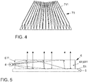
- the polarizing element is a film comprising a plurality of microwalls that restrict the direction of exit of the light. Said microwalls act like a grid that strongly absorbs a polarized component of light, and is very transparent to the other component.
- the photolith film comprises at least one first opaque zone and at least one second transparent zone.
- a graphic element or logo is projected to the exterior thanks to the restriction of the light in the opaque zone, and the transmission of light through the transparent zone.
- the at least one first opaque zone is obtained by applying paint to the photolith film and the at least one second transparent zone is obtained by lasering to remove the paint.
- the paint is removed to allow passage through the transparent zones in the photolith film, which may be a plastic substrate.
- a laser option is more economical than others, and has sufficient accuracy.
- different colours are achieved through a single LED light-emitting member, by providing a plastic substrate of the photolith film with chromatic variation.
- the partially opaque outer cover has a smoked black finish.
- the smoked black finish prevents anyone from seeing the inside and therefore the logo and the rest of the lighting device, whereas, when on, it allows transmission of light, revealing the desired logo lit up.
- the partially opaque outer cover is produced by bi-injection moulding, in which the smoked black finish is injected into an outer face of the structural panel, obtaining said finish simply and without a significant increase in costs.
- the lighting device successively comprises the housing, the reflective element, the light guide and the photolith film, facing the aperture in the structural panel, and covered by the partially opaque outer cover, the reflective element, the light guide, the photolith film and the aperture being superimposed on one another.
- Said arrangement of elements maximizes performance in terms of light efficiency and homogeneity of the photolith film image, i.e. the logo, which is transmitted to the exterior.
- Said arrangement of elements also offers various possibilities as regards the positioning of the light-emitting member, since the latter could be placed facing each of the ends or edges of the light guide in its configuration as a flat plate. Moreover, it helps make the lighting device compact so that it does not take up too much space, especially in the transverse direction, so that the structure of a door, for example, is not affected.
- the lighting device successively comprises the housing, at least one light-emitting member, the photolith film and the polarizing element, facing the aperture in the structural panel, and covered by the partially opaque outer cover, the photolith film, the polarizing element and the aperture being superimposed on one another.
- Said arrangement of elements maximizes performance in terms of confining the field of illumination of the light emitted towards the exterior, to comply with the abovementioned approval requirements so that the lighting device may be switched on while the vehicle is running.
- the lighting device successively comprises the housing, the reflective element, the light guide, the photolith film and the polarizing element, facing the aperture in the structural panel, and covered by the partially opaque outer covering, the reflective element, the light guide, the photolith film, the polarizing element and the aperture being superimposed on one another.
- Said arrangement of elements maximizes performance both in terms of homogeneity and light efficiency, and in terms of confining the field of light emission.
- the invention relates to a lighting arrangement comprising a lighting device intended to be housed in a side area of the vehicle.
- the function of this lighting device is to light up and highlight a logo positioned on a trim on the side of a vehicle.
- a trim usually consists of plastic parts that improve the surface finish of the vehicle and/or hide areas from view from the outside, for example, the plastic covers indicated on the upright A, B or C of the vehicle in Figure 1 .
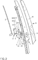
- the lighting arrangement comprises an outer cover 9 on a side area of a vehicle, in which the outer cover 9 comprises a structural panel 1, in which the structural panel 1 comprises an aperture 11, and in which the lighting arrangement comprises a lighting device, whereby the lighting device comprises a housing 3 facing the aperture 11 and defining an interior volume between the housing 3 and the aperture 11 in the structural panel 1, at least one light-emitting member 4 arranged in the interior volume and actuatable in a first on state or a second off state, a photolith film 8 with at least one graphic element 83, in which the photolith film 8 is arranged between the at least one light-emitting member 4 and the structural panel 1, and in which the outer cover 9 is partially opaque, so as to allow the at least one graphic element 83 to be displayed, in which the lighting device comprises at least one light orientation means 6 such that the light emitted by the at least one light-emitting member 4 is reoriented towards the aperture 11 in the structural panel 1, and in which the at least one graphic element 83
- Figure 2 shows a possible use of the present invention for lighting up a logo arranged in the outer cover 9 of an upright B of a vehicle.
- the housing 1 comprises the whole assembly and is used for securing to the internal structure or substrate itself. It also ensures that light does not escape through the ends of the light guide. As can be seen in Figure 2 , it takes the form of a box with a recess that encloses all the intermediate parts so that there is no movement, loss of light, etc.
- the lighting device there are two alternatives for the lighting device, one in which the logo or graphic element 83 is only displayed when the at least one light-emitting member is in a first on state, and another in which the logo or graphic element 83 is also displayed when the at least one light-emitting member is in a second off state, by including, for example, a chrome-plated contour or the like in the photolith film 8.
- the at least one light orientation means 6 comprises a light guide 61.
- said light guide 61 is a methacrylate component with the same geometry as the photolith film 8 to be illuminated, arranged adjacent to and just behind the photolith film 8, in the direction of emission of light towards the aperture 11 in the structural panel 1.
- the light guide 61 is an essentially flat plate, in which the light guide 61 comprises at least one light transmission surface 611 and at least one end 612 where the light emitted by the at least one light-emitting member 4 strikes, so that the at least one light transmission surface 611 is substantially parallel to the photolith film 8.
- the light-emitting member 4 is oriented towards the lower side or end 612 of the light guide, said light-emitting member 4 thus being located at a lower level than said light guide 61.
- the light guide 61 comprises a plurality of optical structures 613 such that the light is dispersed particularly in a direction substantially perpendicular to the at least one light transmission surface 611. The light is thus emitted in a first direction and reflected towards a second direction substantially perpendicular to the first direction.
- the entire light transmission surface 611 is lit up homogeneously, avoiding the creation of auras and divergent light intensities in the logo 8, as well as minimizing the space occupied by the lighting device, especially critical in said transverse direction.
- the lighting device comprises a reflective element 5 arranged between the housing 3 and the light guide 61, so that the reflective element 5 is substantially parallel to the at least one light transmission surface 611 of the light guide 61.
- the reflective element 5 comprises at least one matt white surface 51.
- the at least one light orientation means 6 is a polarizing element 71.
- the polarizing element 71 is a film comprising a plurality of microwalls 711 that restrict the direction of exit of the light.
- the photolith film 8 comprises at least one first opaque zone 81 and at least one second transparent zone 82. It is thus possible to generate, by means of the zones that allow the transmission of light (second transparent zone 82), an element to be illuminated, corresponding to the desired logo or image to be highlighted.
- the at least one first opaque zone 81 is obtained by applying paint to the photolith film 8 and the at least one second transparent zone 82 is obtained by lasering to remove the paint.
- Another alternative to lasering is to make a negative structure similar to the one used in photography. This affords very high definition and precision but, however, is more expensive.
- the partially opaque outer cover 9 has a smoked black finish.
- the invention relates to the illumination of a trim element in such a way that, when the light emitting assembly is off, the lighting system is not visible; the user simply sees a trim element or outer cover 9 with the same quality and appearance as those currently fitted to a motor vehicle. Conversely, when the at least one light-emitting member 4 is in a first on state, the user sees a trim element or moulding with an illuminated figure or logo 8.
- the partially opaque outer cover 9 is produced by bi-injection moulding, in which the smoked black finish is injected into an outer face 91 of the structural panel 1.
- the lighting device successively comprises the housing 3, the reflective element 5, the light guide 61 and the photolith film 8, facing the aperture 11 in the structural panel 1, and covered by the partially opaque outer cover 9, the reflective element 5, the light guide 61, the photolith film 8 and the aperture 11 being superimposed on one another.
- the lighting device successively comprises the housing 3, at least one light-emitting member 4, the photolith film 8 and the polarizing element 71, facing the aperture 11 in the structural panel 1, and covered by the partially opaque outer cover 9, the photolith film 8, the polarizing element 71 and the aperture 11 being superimposed on one another.
- the lighting device successively comprises the housing 3, the reflective element 5, the light guide 61, the photolith film 8 and the polarizing element 71, facing the aperture 11 in the structural panel 1, and covered by the partially opaque outer cover 9, the reflective element 5, the light guide 61, the photolith film 8, the polarizing element 71 and the aperture 11 being superimposed on one another.
- the reflective element 5, the light guide 61 and photolith film 8 are substantially similar in size.
Landscapes
- Engineering & Computer Science (AREA)
- Mechanical Engineering (AREA)
- Physics & Mathematics (AREA)
- General Physics & Mathematics (AREA)
- Theoretical Computer Science (AREA)
- Business, Economics & Management (AREA)
- Accounting & Taxation (AREA)
- Marketing (AREA)
- Arrangements Of Lighting Devices For Vehicle Interiors, Mounting And Supporting Thereof, Circuits Therefore (AREA)
- Lighting Device Outwards From Vehicle And Optical Signal (AREA)
Claims (13)
- Agencement d'éclairage comprenant un couvercle externe (9) pour une zone latérale d'un véhicule, dans lequel le couvercle externe (9) comprend :
un panneau structurel (1) dans lequel le panneau structurel (1) comprend une ouverture (11), et dans lequel l'agencement comprend un dispositif d'éclairage, dans lequel le dispositif d'éclairage comprend :un boîtier (3) faisant face à l'ouverture (11) et définissant un volume intérieur entre le boîtier (3) et l'ouverture (11),au moins un élément d'émission de lumière (4) agencé dans le volume intérieur et pouvant être actionné dans un premier état activé ou un second état désactivé,un film photolithique (8) avec au moins un élément graphique (83), dans lequel le film photolithique (8) est agencé entre le au moins un élément d'émission de lumière (4) et le panneau structurel (1), et dans lequel le couvercle externe (9) est partiellement opaque, afin de permettre d'afficher le au moins un élément graphique (83),caractérisé en ce que le dispositif d'éclairage comprend au moins un moyen d'orientation de lumière (6), dans lequel le au moins un moyen d'orientation de lumière (6) est un élément polarisant (71), de sorte que la direction de la lumière émise par le au moins un élément d'émission de lumière (4) est limitée, confinant le champ d'éclairage de lumière émise vers l'extérieur, et dans lequel le au moins un moyen d'orientation (6) et le film photolithique (8) sont logés dans le volume intérieur entre le boîtier (3) et l'ouverture (11) et sont agencés parallèlement entre eux et superposés l'un sur l'autre. - Agencement selon la revendication 1, caractérisé en ce que le au moins un moyen d'orientation de lumière (6) comprend en outre un guide de lumière (61).
- Agencement selon la revendication 2, caractérisé en ce que le guide de lumière (61) est une plaque essentiellement plate, dans lequel le guide de lumière (61) comprend au moins une surface de transmission de lumière (611) et au moins une extrémité (612) où la lumière émise par le au moins un élément d'émission de lumière (4) se heurte, de sorte que la au moins une surface de transmission de lumière (611) est sensiblement parallèle au film photolithique (8).
- Agencement selon la revendication 2, caractérisé en ce que le guide de lumière (61) comprend une pluralité de structures optiques (613) de sorte que la lumière est dispersée en particulier dans une direction sensiblement perpendiculaire à la au moins une surface de transmission de lumière (611).
- Agencement selon la revendication 2, caractérisé en ce que le dispositif d'éclairage comprend un élément réfléchissant (5) agencé entre le boîtier (3) et le guide de lumière (61), de sorte que l'élément réfléchissant (5) est sensiblement parallèle à la au moins une surface de transmission de lumière (611) du guide de lumière (61).
- Agencement selon la revendication 5, caractérisé en ce que l'élément réfléchissant (5) comprend au moins une surface blanc mat (51).
- Agencement selon la revendication 1, caractérisé en ce que l'élément polarisant (71) est un film comprenant une pluralité de micro-parois (711) qui limitent la direction de sortie de la lumière.
- Agencement selon la revendication 1, caractérisé en ce que le film photolithique (8) comprend au moins une première zone opaque (81) et au moins une seconde zone transparente (82).
- Agencement selon la revendication 8, caractérisé en ce que la au moins une première zone opaque (81) est obtenue en appliquant de la peinture sur le film photolithique (8) et la au moins une seconde zone transparente (82) est obtenue en utilisant un laser pour retirer la peinture.
- Agencement selon la revendication 1, caractérisé en ce que le couvercle externe (9) partiellement opaque a un fini noir fumé.
- Agencement selon la revendication 10, caractérisé en ce que le couvercle externe (9) partiellement opaque est produit par moulage par bi-injection, dans lequel le fini noir fumé est injecté dans une face externe (91) du panneau structurel (1).
- Agencement selon la revendication 1, caractérisé en ce qu'il comprend successivement le boîtier (3), au moins un élément d'émission de lumière (4), le film photolithique (8) et l'élément polarisant (71), faisant face à l'ouverture (11) dans le panneau structurel (1) et recouvert par le couvercle externe (9) partiellement opaque, le film photolithique (8), l'élément polarisant (71) et l'ouverture (11) qui sont superposés les uns sur les autres.
- Agencement selon les revendications 1, 2 et 5, caractérisé en ce qu'il comprend successivement le boîtier (3), l'élément réfléchissant (5), le guide de lumière (61), le film photolithique (8) et l'élément polarisant (71), faisant face à l'ouverture (11) dans le panneau structurel (1) et recouvert par le couvercle externe (9) partiellement opaque, l'élément réfléchissant (5), le guide de lumière (61), le film photolithique (8), l'élément polarisant (71) et l'ouverture (11) qui sont superposés les uns sur les autres.
Applications Claiming Priority (1)
| Application Number | Priority Date | Filing Date | Title |
|---|---|---|---|
| ES201630315A ES2578525B2 (es) | 2016-03-17 | 2016-03-17 | Dispositivo de iluminación para cubierta exterior de un lateral de un vehículo |
Publications (2)
| Publication Number | Publication Date |
|---|---|
| EP3228501A1 EP3228501A1 (fr) | 2017-10-11 |
| EP3228501B1 true EP3228501B1 (fr) | 2022-05-04 |
Family
ID=56418658
Family Applications (1)
| Application Number | Title | Priority Date | Filing Date |
|---|---|---|---|
| EP17382116.6A Active EP3228501B1 (fr) | 2016-03-17 | 2017-03-07 | Dispositif d'éclairage pour un couvercle extérieur sur un côté d'un véhicule |
Country Status (2)
| Country | Link |
|---|---|
| EP (1) | EP3228501B1 (fr) |
| ES (1) | ES2578525B2 (fr) |
Families Citing this family (2)
| Publication number | Priority date | Publication date | Assignee | Title |
|---|---|---|---|---|
| US11346523B2 (en) | 2018-03-13 | 2022-05-31 | Motherson Innovations Company Limited | Light emitting system, a design element, a rear view device, a covering device, and a body component of a vehicle |
| EP3848628A1 (fr) * | 2020-01-09 | 2021-07-14 | Motherson Innovations Company Limited | Système émetteur de lumière, élément de conception, dispositif de vision arrière, dispositif de revêtement et composant de carrosserie d'un véhicule |
Citations (2)
| Publication number | Priority date | Publication date | Assignee | Title |
|---|---|---|---|---|
| EP2062784A2 (fr) * | 2007-11-21 | 2009-05-27 | Aisin Seiki Kabushiki Kaisha | Composant extérieur pour véhicule |
| US9016910B2 (en) * | 2011-06-10 | 2015-04-28 | Adac Plastics, Inc. | Vehicular component incorporating concealable indicia with controlled light transmission |
Family Cites Families (10)
| Publication number | Priority date | Publication date | Assignee | Title |
|---|---|---|---|---|
| JPS5856942A (ja) * | 1981-09-29 | 1983-04-04 | Nissan Motor Co Ltd | 車両用ウインドガラスにおけるマ−ク表示構造 |
| JP4596100B2 (ja) * | 2000-09-28 | 2010-12-08 | 豊田合成株式会社 | 照明装置 |
| US20040090767A1 (en) * | 2002-11-12 | 2004-05-13 | Fu-Cheng Hou | Decorative electro-luminescent strip for automobiles |
| US7901120B2 (en) * | 2007-08-22 | 2011-03-08 | Ccl Design Gmbh | Decorative unit with illuminable decorative elements |
| US8400265B2 (en) * | 2007-09-17 | 2013-03-19 | Magna International Inc. | Touchless keyless entry keypad integrated with electroluminescence backlight |
| JP5115284B2 (ja) * | 2008-04-02 | 2013-01-09 | 豊田合成株式会社 | スカッフプレート |
| JP4945622B2 (ja) * | 2009-10-22 | 2012-06-06 | 株式会社ホンダアクセス | サイドシルガーニッシュ |
| DE102011115685A1 (de) * | 2011-10-11 | 2013-04-11 | GM Global Technology Operations LLC (n. d. Gesetzen des Staates Delaware) | Kraftfahrzeug, insbesondere Personenkraftwagen |
| TWM467584U (zh) * | 2013-09-04 | 2013-12-11 | Chao Wei Prec Co Ltd | 車輛指示燈 |
| ES2500740B1 (es) * | 2014-03-10 | 2015-07-29 | Seat, S.A. | Dispositivo de iluminación para un vehículo |
-
2016
- 2016-03-17 ES ES201630315A patent/ES2578525B2/es active Active
-
2017
- 2017-03-07 EP EP17382116.6A patent/EP3228501B1/fr active Active
Patent Citations (2)
| Publication number | Priority date | Publication date | Assignee | Title |
|---|---|---|---|---|
| EP2062784A2 (fr) * | 2007-11-21 | 2009-05-27 | Aisin Seiki Kabushiki Kaisha | Composant extérieur pour véhicule |
| US9016910B2 (en) * | 2011-06-10 | 2015-04-28 | Adac Plastics, Inc. | Vehicular component incorporating concealable indicia with controlled light transmission |
Non-Patent Citations (1)
| Title |
|---|
| YAO PO-HUNG ET AL: "Polarized backlight with constrained angular divergence for enhancement of light extraction efficiency from wire grid polarizer References and links", J. OPT. SOC. KOREA APPL. PHYS. LETT. J. OPT. SOC. AM. A JPN. J. APPL. PHYS. J. APPL. PHYS. OPT. EXPRESS J. OPT. SOC. KOREA J. DISP. TECHNOL. NOV JAN JAN OPTICS EXPRESS OPT. EXPRESS OPT. LETT. AM. J. PHYS. OPT. LETT, 1 January 2009 (2009-01-01), pages 152 - 157, XP055822939, Retrieved from the Internet <URL:https://www.osapublishing.org/DirectPDFAccess/7DE5F4FB-71C7-4930-98E8588E63851D07_227652/oe-20-5-4819.pdf?da=1&id=227652&seq=0&mobile=no> [retrieved on 20210709] * |
Also Published As
| Publication number | Publication date |
|---|---|
| ES2578525B2 (es) | 2017-01-31 |
| ES2578525A1 (es) | 2016-07-27 |
| EP3228501A1 (fr) | 2017-10-11 |
Similar Documents
| Publication | Publication Date | Title |
|---|---|---|
| US11904762B2 (en) | Vehicular exterior rearview mirror assembly with illumination module | |
| JP5451425B2 (ja) | 車両室内意匠の発光構造 | |
| KR101918467B1 (ko) | 자동차용 기능부품 | |
| US20070159837A1 (en) | Illuminable information unit | |
| JP2016131151A (ja) | 自動車用のアプリケーション構成 | |
| EP3228501B1 (fr) | Dispositif d'éclairage pour un couvercle extérieur sur un côté d'un véhicule | |
| CN112601678A (zh) | 用于机动车的照明装置 | |
| JP2019200937A (ja) | 車両用灯具 | |
| JP4218643B2 (ja) | 指針計器 | |
| JP2007085858A (ja) | 車両用指針計器 | |
| JP2014094656A (ja) | 加飾照明装置 | |
| EP3783259B1 (fr) | Dispositif d'éclairage pour véhicule | |
| US11237318B1 (en) | Light for a motor vehicle | |
| JP2009051277A (ja) | 車両用照明装置 | |
| JP2019131029A (ja) | 乗物用照明装置 | |
| KR100879128B1 (ko) | 입체 식별기능을 갖는 계기판 | |
| JP2018199388A (ja) | 乗物用照明装置 | |
| US20210005120A1 (en) | Lamp assembly | |
| JP4615974B2 (ja) | 車両用指針計器 | |
| JP4259480B2 (ja) | 車両用計器 | |
| JP4265514B2 (ja) | 車両用指針計器 | |
| JP7223532B2 (ja) | 道路の照明、信号の発信、又は、内部照明のための発光デバイス | |
| CN218986517U (zh) | 一种车门内拉手及车辆 | |
| JP7139140B2 (ja) | 車両用照明装置、車両用灯具、車両用灯具付きウィンドウパネル、車載ディスプレイ | |
| JP2019001239A (ja) | 車両用照明装置 |
Legal Events
| Date | Code | Title | Description |
|---|---|---|---|
| PUAI | Public reference made under article 153(3) epc to a published international application that has entered the european phase |
Free format text: ORIGINAL CODE: 0009012 |
|
| STAA | Information on the status of an ep patent application or granted ep patent |
Free format text: STATUS: THE APPLICATION HAS BEEN PUBLISHED |
|
| AK | Designated contracting states |
Kind code of ref document: A1 Designated state(s): AL AT BE BG CH CY CZ DE DK EE ES FI FR GB GR HR HU IE IS IT LI LT LU LV MC MK MT NL NO PL PT RO RS SE SI SK SM TR |
|
| AX | Request for extension of the european patent |
Extension state: BA ME |
|
| STAA | Information on the status of an ep patent application or granted ep patent |
Free format text: STATUS: REQUEST FOR EXAMINATION WAS MADE |
|
| 17P | Request for examination filed |
Effective date: 20180411 |
|
| TPAC | Observations filed by third parties |
Free format text: ORIGINAL CODE: EPIDOSNTIPA |
|
| TPAC | Observations filed by third parties |
Free format text: ORIGINAL CODE: EPIDOSNTIPA |
|
| STAA | Information on the status of an ep patent application or granted ep patent |
Free format text: STATUS: EXAMINATION IS IN PROGRESS |
|
| STAA | Information on the status of an ep patent application or granted ep patent |
Free format text: STATUS: EXAMINATION IS IN PROGRESS |
|
| 17Q | First examination report despatched |
Effective date: 20201103 |
|
| GRAP | Despatch of communication of intention to grant a patent |
Free format text: ORIGINAL CODE: EPIDOSNIGR1 |
|
| STAA | Information on the status of an ep patent application or granted ep patent |
Free format text: STATUS: GRANT OF PATENT IS INTENDED |
|
| INTG | Intention to grant announced |
Effective date: 20211018 |
|
| GRAS | Grant fee paid |
Free format text: ORIGINAL CODE: EPIDOSNIGR3 |
|
| GRAA | (expected) grant |
Free format text: ORIGINAL CODE: 0009210 |
|
| STAA | Information on the status of an ep patent application or granted ep patent |
Free format text: STATUS: THE PATENT HAS BEEN GRANTED |
|
| AK | Designated contracting states |
Kind code of ref document: B1 Designated state(s): AL AT BE BG CH CY CZ DE DK EE ES FI FR GB GR HR HU IE IS IT LI LT LU LV MC MK MT NL NO PL PT RO RS SE SI SK SM TR |
|
| REG | Reference to a national code |
Ref country code: GB Ref legal event code: FG4D |
|
| REG | Reference to a national code |
Ref country code: CH Ref legal event code: EP |
|
| REG | Reference to a national code |
Ref country code: AT Ref legal event code: REF Ref document number: 1488723 Country of ref document: AT Kind code of ref document: T Effective date: 20220515 |
|
| REG | Reference to a national code |
Ref country code: IE Ref legal event code: FG4D Ref country code: DE Ref legal event code: R096 Ref document number: 602017056847 Country of ref document: DE |
|
| REG | Reference to a national code |
Ref country code: LT Ref legal event code: MG9D |
|
| REG | Reference to a national code |
Ref country code: NL Ref legal event code: MP Effective date: 20220504 |
|
| REG | Reference to a national code |
Ref country code: AT Ref legal event code: MK05 Ref document number: 1488723 Country of ref document: AT Kind code of ref document: T Effective date: 20220504 |
|
| PG25 | Lapsed in a contracting state [announced via postgrant information from national office to epo] |
Ref country code: SE Free format text: LAPSE BECAUSE OF FAILURE TO SUBMIT A TRANSLATION OF THE DESCRIPTION OR TO PAY THE FEE WITHIN THE PRESCRIBED TIME-LIMIT Effective date: 20220504 Ref country code: PT Free format text: LAPSE BECAUSE OF FAILURE TO SUBMIT A TRANSLATION OF THE DESCRIPTION OR TO PAY THE FEE WITHIN THE PRESCRIBED TIME-LIMIT Effective date: 20220905 Ref country code: NO Free format text: LAPSE BECAUSE OF FAILURE TO SUBMIT A TRANSLATION OF THE DESCRIPTION OR TO PAY THE FEE WITHIN THE PRESCRIBED TIME-LIMIT Effective date: 20220804 Ref country code: NL Free format text: LAPSE BECAUSE OF FAILURE TO SUBMIT A TRANSLATION OF THE DESCRIPTION OR TO PAY THE FEE WITHIN THE PRESCRIBED TIME-LIMIT Effective date: 20220504 Ref country code: LT Free format text: LAPSE BECAUSE OF FAILURE TO SUBMIT A TRANSLATION OF THE DESCRIPTION OR TO PAY THE FEE WITHIN THE PRESCRIBED TIME-LIMIT Effective date: 20220504 Ref country code: HR Free format text: LAPSE BECAUSE OF FAILURE TO SUBMIT A TRANSLATION OF THE DESCRIPTION OR TO PAY THE FEE WITHIN THE PRESCRIBED TIME-LIMIT Effective date: 20220504 Ref country code: GR Free format text: LAPSE BECAUSE OF FAILURE TO SUBMIT A TRANSLATION OF THE DESCRIPTION OR TO PAY THE FEE WITHIN THE PRESCRIBED TIME-LIMIT Effective date: 20220805 Ref country code: FI Free format text: LAPSE BECAUSE OF FAILURE TO SUBMIT A TRANSLATION OF THE DESCRIPTION OR TO PAY THE FEE WITHIN THE PRESCRIBED TIME-LIMIT Effective date: 20220504 Ref country code: ES Free format text: LAPSE BECAUSE OF FAILURE TO SUBMIT A TRANSLATION OF THE DESCRIPTION OR TO PAY THE FEE WITHIN THE PRESCRIBED TIME-LIMIT Effective date: 20220504 Ref country code: BG Free format text: LAPSE BECAUSE OF FAILURE TO SUBMIT A TRANSLATION OF THE DESCRIPTION OR TO PAY THE FEE WITHIN THE PRESCRIBED TIME-LIMIT Effective date: 20220804 Ref country code: AT Free format text: LAPSE BECAUSE OF FAILURE TO SUBMIT A TRANSLATION OF THE DESCRIPTION OR TO PAY THE FEE WITHIN THE PRESCRIBED TIME-LIMIT Effective date: 20220504 |
|
| PG25 | Lapsed in a contracting state [announced via postgrant information from national office to epo] |
Ref country code: RS Free format text: LAPSE BECAUSE OF FAILURE TO SUBMIT A TRANSLATION OF THE DESCRIPTION OR TO PAY THE FEE WITHIN THE PRESCRIBED TIME-LIMIT Effective date: 20220504 Ref country code: PL Free format text: LAPSE BECAUSE OF FAILURE TO SUBMIT A TRANSLATION OF THE DESCRIPTION OR TO PAY THE FEE WITHIN THE PRESCRIBED TIME-LIMIT Effective date: 20220504 Ref country code: LV Free format text: LAPSE BECAUSE OF FAILURE TO SUBMIT A TRANSLATION OF THE DESCRIPTION OR TO PAY THE FEE WITHIN THE PRESCRIBED TIME-LIMIT Effective date: 20220504 Ref country code: IS Free format text: LAPSE BECAUSE OF FAILURE TO SUBMIT A TRANSLATION OF THE DESCRIPTION OR TO PAY THE FEE WITHIN THE PRESCRIBED TIME-LIMIT Effective date: 20220904 |
|
| PG25 | Lapsed in a contracting state [announced via postgrant information from national office to epo] |
Ref country code: SM Free format text: LAPSE BECAUSE OF FAILURE TO SUBMIT A TRANSLATION OF THE DESCRIPTION OR TO PAY THE FEE WITHIN THE PRESCRIBED TIME-LIMIT Effective date: 20220504 Ref country code: SK Free format text: LAPSE BECAUSE OF FAILURE TO SUBMIT A TRANSLATION OF THE DESCRIPTION OR TO PAY THE FEE WITHIN THE PRESCRIBED TIME-LIMIT Effective date: 20220504 Ref country code: RO Free format text: LAPSE BECAUSE OF FAILURE TO SUBMIT A TRANSLATION OF THE DESCRIPTION OR TO PAY THE FEE WITHIN THE PRESCRIBED TIME-LIMIT Effective date: 20220504 Ref country code: EE Free format text: LAPSE BECAUSE OF FAILURE TO SUBMIT A TRANSLATION OF THE DESCRIPTION OR TO PAY THE FEE WITHIN THE PRESCRIBED TIME-LIMIT Effective date: 20220504 Ref country code: DK Free format text: LAPSE BECAUSE OF FAILURE TO SUBMIT A TRANSLATION OF THE DESCRIPTION OR TO PAY THE FEE WITHIN THE PRESCRIBED TIME-LIMIT Effective date: 20220504 Ref country code: CZ Free format text: LAPSE BECAUSE OF FAILURE TO SUBMIT A TRANSLATION OF THE DESCRIPTION OR TO PAY THE FEE WITHIN THE PRESCRIBED TIME-LIMIT Effective date: 20220504 |
|
| REG | Reference to a national code |
Ref country code: DE Ref legal event code: R097 Ref document number: 602017056847 Country of ref document: DE |
|
| PLBE | No opposition filed within time limit |
Free format text: ORIGINAL CODE: 0009261 |
|
| STAA | Information on the status of an ep patent application or granted ep patent |
Free format text: STATUS: NO OPPOSITION FILED WITHIN TIME LIMIT |
|
| PG25 | Lapsed in a contracting state [announced via postgrant information from national office to epo] |
Ref country code: AL Free format text: LAPSE BECAUSE OF FAILURE TO SUBMIT A TRANSLATION OF THE DESCRIPTION OR TO PAY THE FEE WITHIN THE PRESCRIBED TIME-LIMIT Effective date: 20220504 |
|
| 26N | No opposition filed |
Effective date: 20230207 |
|
| PGFP | Annual fee paid to national office [announced via postgrant information from national office to epo] |
Ref country code: FR Payment date: 20230323 Year of fee payment: 7 |
|
| PG25 | Lapsed in a contracting state [announced via postgrant information from national office to epo] |
Ref country code: SI Free format text: LAPSE BECAUSE OF FAILURE TO SUBMIT A TRANSLATION OF THE DESCRIPTION OR TO PAY THE FEE WITHIN THE PRESCRIBED TIME-LIMIT Effective date: 20220504 |
|
| P01 | Opt-out of the competence of the unified patent court (upc) registered |
Effective date: 20230527 |
|
| PG25 | Lapsed in a contracting state [announced via postgrant information from national office to epo] |
Ref country code: MC Free format text: LAPSE BECAUSE OF FAILURE TO SUBMIT A TRANSLATION OF THE DESCRIPTION OR TO PAY THE FEE WITHIN THE PRESCRIBED TIME-LIMIT Effective date: 20220504 |
|
| REG | Reference to a national code |
Ref country code: CH Ref legal event code: PL |
|
| REG | Reference to a national code |
Ref country code: BE Ref legal event code: MM Effective date: 20230331 |
|
| PG25 | Lapsed in a contracting state [announced via postgrant information from national office to epo] |
Ref country code: LU Free format text: LAPSE BECAUSE OF NON-PAYMENT OF DUE FEES Effective date: 20230307 |
|
| REG | Reference to a national code |
Ref country code: IE Ref legal event code: MM4A |
|
| PG25 | Lapsed in a contracting state [announced via postgrant information from national office to epo] |
Ref country code: LI Free format text: LAPSE BECAUSE OF NON-PAYMENT OF DUE FEES Effective date: 20230331 Ref country code: IT Free format text: LAPSE BECAUSE OF FAILURE TO SUBMIT A TRANSLATION OF THE DESCRIPTION OR TO PAY THE FEE WITHIN THE PRESCRIBED TIME-LIMIT Effective date: 20220504 Ref country code: IE Free format text: LAPSE BECAUSE OF NON-PAYMENT OF DUE FEES Effective date: 20230307 Ref country code: CH Free format text: LAPSE BECAUSE OF NON-PAYMENT OF DUE FEES Effective date: 20230331 |
|
| PG25 | Lapsed in a contracting state [announced via postgrant information from national office to epo] |
Ref country code: BE Free format text: LAPSE BECAUSE OF NON-PAYMENT OF DUE FEES Effective date: 20230331 |
|
| PGFP | Annual fee paid to national office [announced via postgrant information from national office to epo] |
Ref country code: DE Payment date: 20240328 Year of fee payment: 8 Ref country code: GB Payment date: 20240319 Year of fee payment: 8 |