EP3228443A1 - Verfahren zum ablängen eines reifenbauteiles - Google Patents
Verfahren zum ablängen eines reifenbauteiles Download PDFInfo
- Publication number
- EP3228443A1 EP3228443A1 EP16164011.5A EP16164011A EP3228443A1 EP 3228443 A1 EP3228443 A1 EP 3228443A1 EP 16164011 A EP16164011 A EP 16164011A EP 3228443 A1 EP3228443 A1 EP 3228443A1
- Authority
- EP
- European Patent Office
- Prior art keywords
- tire
- tire component
- servicer
- building drum
- component
- Prior art date
- Legal status (The legal status is an assumption and is not a legal conclusion. Google has not performed a legal analysis and makes no representation as to the accuracy of the status listed.)
- Granted
Links
Images
Classifications
-
- B—PERFORMING OPERATIONS; TRANSPORTING
- B29—WORKING OF PLASTICS; WORKING OF SUBSTANCES IN A PLASTIC STATE IN GENERAL
- B29D—PRODUCING PARTICULAR ARTICLES FROM PLASTICS OR FROM SUBSTANCES IN A PLASTIC STATE
- B29D30/00—Producing pneumatic or solid tyres or parts thereof
- B29D30/06—Pneumatic tyres or parts thereof (e.g. produced by casting, moulding, compression moulding, injection moulding, centrifugal casting)
- B29D30/38—Textile inserts, e.g. cord or canvas layers, for tyres; Treatment of inserts prior to building the tyre
- B29D30/46—Cutting textile inserts to required shape
-
- B—PERFORMING OPERATIONS; TRANSPORTING
- B26—HAND CUTTING TOOLS; CUTTING; SEVERING
- B26D—CUTTING; DETAILS COMMON TO MACHINES FOR PERFORATING, PUNCHING, CUTTING-OUT, STAMPING-OUT OR SEVERING
- B26D1/00—Cutting through work characterised by the nature or movement of the cutting member or particular materials not otherwise provided for; Apparatus or machines therefor; Cutting members therefor
- B26D1/01—Cutting through work characterised by the nature or movement of the cutting member or particular materials not otherwise provided for; Apparatus or machines therefor; Cutting members therefor involving a cutting member which does not travel with the work
- B26D1/04—Cutting through work characterised by the nature or movement of the cutting member or particular materials not otherwise provided for; Apparatus or machines therefor; Cutting members therefor involving a cutting member which does not travel with the work having a linearly-movable cutting member
-
- B—PERFORMING OPERATIONS; TRANSPORTING
- B26—HAND CUTTING TOOLS; CUTTING; SEVERING
- B26D—CUTTING; DETAILS COMMON TO MACHINES FOR PERFORATING, PUNCHING, CUTTING-OUT, STAMPING-OUT OR SEVERING
- B26D3/00—Cutting work characterised by the nature of the cut made; Apparatus therefor
- B26D3/003—Cutting work characterised by the nature of the cut made; Apparatus therefor specially adapted for cutting rubber
-
- B—PERFORMING OPERATIONS; TRANSPORTING
- B26—HAND CUTTING TOOLS; CUTTING; SEVERING
- B26D—CUTTING; DETAILS COMMON TO MACHINES FOR PERFORATING, PUNCHING, CUTTING-OUT, STAMPING-OUT OR SEVERING
- B26D7/00—Details of apparatus for cutting, cutting-out, stamping-out, punching, perforating, or severing by means other than cutting
- B26D7/01—Means for holding or positioning work
- B26D7/02—Means for holding or positioning work with clamping means
- B26D7/025—Means for holding or positioning work with clamping means acting upon planar surfaces
-
- B—PERFORMING OPERATIONS; TRANSPORTING
- B29—WORKING OF PLASTICS; WORKING OF SUBSTANCES IN A PLASTIC STATE IN GENERAL
- B29D—PRODUCING PARTICULAR ARTICLES FROM PLASTICS OR FROM SUBSTANCES IN A PLASTIC STATE
- B29D30/00—Producing pneumatic or solid tyres or parts thereof
- B29D30/06—Pneumatic tyres or parts thereof (e.g. produced by casting, moulding, compression moulding, injection moulding, centrifugal casting)
- B29D30/38—Textile inserts, e.g. cord or canvas layers, for tyres; Treatment of inserts prior to building the tyre
- B29D30/46—Cutting textile inserts to required shape
- B29D2030/463—Holding the textile inserts during cutting; means therefor
Definitions
- the invention relates to a method for cutting a tire component.
- Tire components in the form of rubber strips are fixed along a cutting strip before a cutting operation.
- the fixation of the tire component is therefore important in order to achieve a straight cutting edge on the tire component.
- the object of the invention was to provide a method with which conventional cutting processes for tire components are improved.
- An advantage of the invention is to be seen in particular in that the cutting quality on the tire component to be cut is considerably improved by the method according to the invention.
- the tire component is pressed on its upper side with the flexible hold-down against the top of the Servicers.
- the hold-down is characterized by a particularly high degree of flexibility, since the individual fingers are each flexibly connected to the comb-shaped main body of the hold-down device with individual tubular connection means. Thereby, the tire component is pressed against the Servicer only with such a high contact pressure, as is necessary for the cutting process.
- Another advantage is that the beginning and end of the tire component on the servicer are always in the same place in a straight line to allow automatic assembly. This results in a cycle time improvement of 10% to 15%.
- the tubular connecting means consist of a flexible plastic material.
- the tubular connecting means has optimum rigidity.
- the individual fingers are connected both firmly and flexibly to the main body of the hold-down.
- the individual fingers have a length of 30 to 40 mm. As a result, the individual fingers can optimally adapt to the contour of the tire component.
- the individual fingers have a width of 6 to 7 mm. In this way, the fingers can exert sufficient contact pressure on the tire component.
- the tire component is a side wall for a vehicle tire. Due to the special cross-sectional contour of the side wall, a secure fixation on the servicer is required.
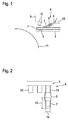
- the Fig. 1 shows an embodiment of the method.
- a side view of the hold-down 4 with the tire component 1 and the servicer 5 is shown.
- the tire component 1 which is preferably a side wall for a vehicle tire, is conveyed after a cutting operation with the servicer 5 in the direction of the schematically illustrated carcass drum 11. On the top of the servicer 5, the tire component 1 is applied.
- the front end of the tire component 1 is gripped by vacuum cups 12 and on the Top 11 of the schematically illustrated Karkasstrommel positioned.
- On the carcass drum other tire components, such as the inner tire and the fabric are already wound.
- the carcass drum then rotates, winding the sidewall onto the carcass drum.
- the hold-down 4 presses the tire component 1 with a plurality of individual fingers 7 against the upper side of the servicer 5 to prepare the cutting operation of the tire component 1.
- the hold-down device 4 consists of a comb-shaped main body 9, tubular connecting means 8 and individual fingers 7.
- the fingers 7 are connected to each other with a tubular connecting means 8, with the base body 9 in the manner shown.
- the rear end of the finger 7 is in the front end of the tubular connecting means 8.
- the front of the comb-shaped body is in the rear end of the tubular connecting means 8.
- the hold-down 4 is connected at the rear with a lifting and lowering device 10. After the cutting operation, the fixation of the tire component on the servicer is not released, wherein the lifting device 10 always presses with the hold-down 4 on the tire component 1. As a result, the tire component 1 can no longer move, so that the beginning and the end are always positioned in the same direction in the lateral direction and the tire component can not slip backwards.
- the cutting device 6 is then also moved back to a waiting position.
- vacuum testers 3 are schematically illustrated, which fix the tire component 1 via a vacuum with the top side of the servicer 5.
- the FIG. 2 shows the hold-4 in a plan.
- the comb-shaped main body 9 has a plurality of individual projections 15.
- the front end of the projection 15 is in the upper end of the tubular connecting means 8.
- the rear end of the finger 7 is in the lower end of the tubular connecting means 8.
- the individual fingers 7 are connected to the projection 15 on the main body 9 with a high degree of flexibility.
- single fingers 7 are arranged in the same way. To simplify the illustration, only one finger 7 is shown.
- the hold-down device 4 generally has between 15 and 30 individual fingers, which are each arranged parallel to the main body 9 of the hold-down 4.
- the length 13 of each finger is between 30 and 40 mm.
- the width 14 of the fingers 7 is about 6 mm.
Landscapes
- Engineering & Computer Science (AREA)
- Mechanical Engineering (AREA)
- Life Sciences & Earth Sciences (AREA)
- Forests & Forestry (AREA)
- Textile Engineering (AREA)
- Tyre Moulding (AREA)
Abstract
Description
- Die Erfindung betrifft ein Verfahren zum Ablängen eines Reifenbauteiles.
- Reifenbauteile in Form von Gummistreifen werden vor einem Schneidvorgang entlang einer Schneidleiste fixiert.
Die Fixierung des Reifenbauteiles ist deshalb wichtig, um eine gerade Schnittkante am Reifenbauteil zu erzielen. Es gibt unterschiedliche Vorrichtungen und Verfahren das Reifenbauteil vor dem Schneidvorgang einzuklemmen. - Der Erfindung lag die Aufgabe zugrunde, ein Verfahren bereitzustellen, mit dem herkömmliche Schneidverfahren für Reifenbauteile verbessert werden.
- Gelöst wird die Aufgabe durch ein Verfahren mit folgenden Schritten:
- a) Transportieren eines vorderen Endabschnittes eines Reifenbauteiles (1) zu einer Reifenbautrommel,
wobei der vordere Endabschnittes des Reifenbauteiles (1) mit einem Transportmittel (12) auf der Oberseite der Reifenbautrommel (11) positioniert wird,
wobei nachfolgend die Reifenbautrommel durch Rotation das Reifenbauteil auf der Reifenbautrommel aufwickelt und das abzulängende Reifenbauteil (1) auf einem Servicer (5) gefördert wird, - b) Positionieren des abzulängenden Reifenbauteiles (1) auf dem Servicer (1) unter einer Schneidvorrichtung (6),
- c) Fixierung des Reifenbauteiles (1) gegen die Oberseite des vorderen Ende des Servicers (5) mit einer im Wesentlichen gleichmäßigen Druckkraft,
wobei das Reifenbauteil (1) an seiner Oberseite mit einem flexiblen Niederhalter (4) gegen die Oberseite des Servicers (5) gedrückt wird,
wobei der Niederhalter (4) in Form eines Kammes ausgebildet ist,
einzelne Finger (7) aufweist und die einzelnen Finger (7) jeweils mit einzelnen schlauchförmigen Verbindungsmittel (8) flexibel mit dem Grundkörper (9) des Niederhalter (4) verbunden sind, - d) Durchführen des Schneidvorganges mit einer Schneidvorrichtung (6),
wobei die Schneidvorrichtung (1) mit einer im Wesentlichen gleichbleibenden Geschwindigkeit entlang der Schneidleiste geführt wird und dabei das Reifenbauteil (1) durchtrennt, - e) Transport des abgelängten hinteren Ende des Reifenbauteiles (1) zu der Reifenaufbautrommel (11),
wobei das hintere Ende des Reifenbauteiles (1) mit einem Transportmittel (12) an das vordere Ende des Reifenbauteiles auf der Reifenaufbautrommel (11) angelegt wird. - Ein Vorteil der Erfindung ist insbesondere darin zu sehen, dass durch das erfindungsgemäße Verfahren die Schnittqualität am abzulängenden Reifenbauteil erheblich verbesssert wird.
Das Reifenbauteil wird an seiner Oberseite mit dem flexiblen Niederhalter gegen die Oberseite des Servicers gedrückt. Der Niederhalter zeichnet sich durch eine besonders hohe Flexibilität aus, da die einzelnen Finger jeweils mit einzelnen schlauchförmigen Verbindungsmitteln flexibel mit dem kammförmigen Grundkörper des Niederhalters verbunden sind. Dadurch wird das Reifenbauteil nur mit einem so hohen Anpressdruck gegen den Servicer gedrückt, wie es für den Schneidvorgang notwendig ist.
Ein weiterer Vorteil besteht darin, dass der Anfang und das Ende des Reifenbauteiles auf dem Servicer immer am gleichen Ort in eine grade Linie liegen, um das automatische Zusammensetzen zu ermöglichen. Dadurch kommt es zu einer Zykluszeitverbesserung von 10 % bis 15%. - In einer vorteilhaften Weiterbildung der Erfindung ist vorgesehen, dass die schlauchförmigen Verbindungsmittel aus einem flexiblen Kunststoffmaterial bestehen.
- Dadurch besitzt das schlauchförmige Verbindungsmittel eine optimale Steifigkeit. Dadurch werden die einzelnen Finger sowohl fest, als auch flexibel mit dem Grundkörper des Niederhalters verbunden.
- In einer weiteren vorteilhaften Weiterbildung der Erfindung ist vorgesehen, dass die einzelnen Finger eine Länge von 30 bis 40 mm aufweisen.
Dadurch können sich die einzelnen Finger optimal der Kontur des Reifenbauteiles anpassen. - In einer weiteren vorteilhaften Weiterbildung der Erfindung ist vorgesehen, dass die einzelnen Finger eine Breite von 6 bis 7 mm aufweisen.
Auf diese Weise können die Finger einen ausreichenden Anpressdruck auf das Reifenbauteil ausüben. - In einer weiteren vorteilhaften Weiterbildung der Erfindung ist vorgesehen, dass das Reifenbauteil eine Seitenwand für einen Fahrzeugreifen ist.
Aufgrund der speziellen Querschnittskontur der Seitenwand ist eine sichere Fixierung auf dem Servicer erforderlich. - Anhand eines Ausführungsbeispiels soll die Erfindung näher erläutert werden. Es zeigt:
- Fig. 1:
- ein Ausführungsbeispiel des erfindungsgemäßen Verfahrens,
- Fig. 2:
- einen Ausschnitt des Niederhalters in einer Aufsicht.
- Die
Fig. 1 zeigt ein Ausführungsbeispiel des Verfahrens. - Es ist eine Seitenansicht des Niederhalters 4 mit dem Reifenbauteil 1 und dem Servicer 5 dargestellt. Das Reifenbauteil 1, bei dem es sich vorzugsweise um eine Seitenwand für ein Fahrzeugreifen handelt, wird nach einem Schneidvorgang mit dem Servicer 5 in Richtung der schematisch dargestellten Karkasstrommel 11 gefördert. Auf der Oberseite des Servicers 5 liegt das Reifenbauteil 1 an.
- Das vordere Ende des Reifenbauteiles 1 wird von Vakuumsaugern 12 gegriffen und auf die Oberseite 11 der schematisch dargestellten Karkasstrommel positioniert. Auf der Karkasstrommel sind bereits weitere Reifenbauteile, wie beispielsweise die Reifeninnenseele und das Gewebe aufgewickelt. Anschließend rotiert die Karkasstrommel und wickelt dabei die Seitenwand auf die Karkasstrommel auf.
- Der Niederhalter 4 drückt das Reifenbauteil 1 mit einer Vielzahl von einzelnen Fingern 7 gegen die Oberseite des Servicers 5 an, um den Schneidvorgang des Reifenbauteiles 1 vorzubereiten. Der Niederhalter 4 besteht aus einem kammförmigen Grundkörper 9, schlauchförmigen Verbindungsmitteln 8 und einzelnen Fingern 7. Die Finger 7 sind jeweils mit einem schlauchförmigen Verbindungsmittel 8, mit dem Grundkörper 9 in der dargestellten Weise miteinander verbunden. Das hintere Ende des Fingers 7 steckt im vorderen Ende des schlauchförmigen Verbindungsmittels 8. Die Vorderseite des kammförmigen Grundkörper steckt im hinteren Ende des schlauchförmigen Verbindungsmittels 8. Durch diese Art der Verbindung besitzt der Niederhalter 4 eine hohe Flexibilität. Das Reifenbauteil 1 kann dadurch mit einem optimalen Anpressdruck gegen den Servicer 5 gedrückt werden, um anschließend den Schneidvorgang durchzuführen. Der Niederhalter 4 ist an der Rückseite mit einer Hebe- und Senkvorrichtung 10 verbunden. Nach dem Schneidvorgang wird die Fixierung des Reifenbauteiles auf dem Servicer nicht gelöst, wobei die Hebevorrichtung 10 mit dem Niederhalter 4 immer auf das Reifenbauteil 1 drückt.
Das Reifenbauteil 1 kann sich dadurch nicht mehr bewegen, so dass der Anfang und das Ende immer in lateraler Richtung gleich positioniert sind und das Reifenbauteil nicht nach hinten rutschen kann.
Die Schneidvorrichtung 6 wird dann ebenfalls in eine Warteposition zurück verfahren. Am vorderen Ende des Servicers 5 sind schematisch Vakuumnester 3 dargestellt, die das Reifenbauteil 1 über ein Vakuum mit der Oberseite des Servicers 5 fixieren. - Die
Figur 2 zeigt den Niederhalter 4 in einer Aufsicht. Der kammförmige Grundkörper 9 weist eine Vielzahl von einzelnen Vorsprüngen 15 auf. Das vordere Ende des Vorsprunges 15 steckt im oberen Ende des schlauchförmigen Verbindungsmittels 8. Das hintere Ende des Fingers 7 steckt im unteren Ende des schlauchförmigen Verbindungsmittels 8. Dadurch sind die einzelnen Finger 7 mit einer hohen Flexibilität mit dem Vorsprung 15 am Grundkörper 9 verbunden. An den weiteren Vorsprüngen 15 sind in gleicherweise einzelne Finger 7 angeordnet. Zur Vereinfachung der Darstellung ist nur ein Finger 7 dargestellt. Der Niederhalter 4 weist im Allgemeinen zwischen 15 und 30 einzelne Finger auf, die jeweils parallel am Grundkörper 9 des Niederhalters 4 angeordnet sind. Die Länge 13 der einzelnen Finger beträgt zwischen 30 und 40 mm. Die Breite 14 der Finger 7 beträgt ca. 6 mm. -
- 1
- Reifenbauteil (Reifenseitenwand)
- 2
- Schneidleiste
- 3
- Vakuumnester
- 4
- Niederhalter
- 5
- Servicer
- 6
- Schneidvorrichtung (Schneidmesser)
- 7
- Einzelner Finger
- 8
- schlauchförmiges Verbindungsmittel
- 9
- Grundkörper des Niederhalters
- 10
- Hebevorrichtung
- 11
- Oberseite der schematisch dargestellten Karkasstrommel
- 12
- Vakuumsauger
- 13
- Länge des Fingers
- 14
- Breite des Fingers
- 15
- Vorsprünge am Grundkörper
Claims (5)
- Verfahren zum Ablängen eines Reifenbauteiles (1) aus einem Elastomer für die Herstellung eines Reifenrohlings, mit folgenden Schritten:a) Transportieren eines vorderen Endabschnittes eines Reifenbauteiles (1) zu einer Reifenbautrommel,
wobei der vordere Endabschnittes des Reifenbauteiles (1) mit einem Transportmittel (12) auf der Oberseite der Reifenbautrommel (11) positioniert wird,
wobei nachfolgend die Reifenbautrommel durch Rotation das Reifenbauteil auf der Reifenbautrommel aufwickelt und das abzulängende Reifenbauteil (1) auf einem Servicer (5) gefördert wird,b) Positionieren des abzulängenden Reifenbauteiles (1) auf dem Servicer (1) unter einer Schneidvorrichtung (6),c) Fixierung des Reifenbauteiles (1) gegen die Oberseite des vorderen Ende des Servicers (5) mit einer im Wesentlichen gleichmäßigen Druckkraft,
wobei das Reifenbauteil (1) an seiner Oberseite mit einem flexiblen Niederhalter (4) gegen die Oberseite des Servicers (5) gedrückt wird,
wobei der Niederhalter (4) in Form eines Kammes ausgebildet ist,
einzelne Finger (7) aufweist und die einzelnen Finger (7) jeweils mit einzelnen schlauchförmigen Verbindungsmittel (8) flexibel mit dem Grundkörper (9) des Niederhalter (4) verbunden sind,d) Durchführen des Schneidvorganges mit einer Schneidvorrichtung (6),
wobei die Schneidvorrichtung (1) mit einer im Wesentlichen gleichbleibenden Geschwindigkeit entlang der Schneidleiste geführt wird und dabei das Reifenbauteil (1) durchtrennt,e) Transport des abgelängten hinteren Ende des Reifenbauteiles (1) zu der Reifenaufbautrommel (11),
wobei das hintere Ende des Reifenbauteiles (1) mit einem Transportmittel (12) an das vordere Ende des Reifenbauteiles auf der Reifenaufbautrommel (11) angelegt wird. - Verfahren nach Anspruch 1,
dadurch gekennzeichnet, dass
die schlauchförmigen Verbindungsmittel (8) aus einem flexiblen Kunststoffmaterial bestehen. - Verfahren nach einem der vorhergehenden Ansprüche,
dadurch gekennzeichnet, dass
die einzelnen Finger (7) eine Länge von 30 bis 40 mm aufweisen. - Verfahren nach einem der vorhergehenden Ansprüche,
dadurch gekennzeichnet, dass
die einzelnen Finger (7) eine Breite von 6 bis 7 mm aufweisen. - Verfahren nach einem der vorhergehenden Ansprüche,
dadurch gekennzeichnet, dass
das Reifenbauteil (1) eine Seitenwand für einen Fahrzeugreifen ist.
Priority Applications (1)
| Application Number | Priority Date | Filing Date | Title |
|---|---|---|---|
| EP16164011.5A EP3228443B1 (de) | 2016-04-06 | 2016-04-06 | Verfahren zum ablängen eines reifenbauteiles |
Applications Claiming Priority (1)
| Application Number | Priority Date | Filing Date | Title |
|---|---|---|---|
| EP16164011.5A EP3228443B1 (de) | 2016-04-06 | 2016-04-06 | Verfahren zum ablängen eines reifenbauteiles |
Publications (2)
| Publication Number | Publication Date |
|---|---|
| EP3228443A1 true EP3228443A1 (de) | 2017-10-11 |
| EP3228443B1 EP3228443B1 (de) | 2020-11-04 |
Family
ID=55699473
Family Applications (1)
| Application Number | Title | Priority Date | Filing Date |
|---|---|---|---|
| EP16164011.5A Active EP3228443B1 (de) | 2016-04-06 | 2016-04-06 | Verfahren zum ablängen eines reifenbauteiles |
Country Status (1)
| Country | Link |
|---|---|
| EP (1) | EP3228443B1 (de) |
Citations (6)
| Publication number | Priority date | Publication date | Assignee | Title |
|---|---|---|---|---|
| JPS58191138A (ja) * | 1982-05-04 | 1983-11-08 | Yokohama Rubber Co Ltd:The | 帯状材料の切断方法 |
| DE3823269A1 (de) * | 1987-07-09 | 1989-01-26 | Bridgestone Corp | Vorrichtung zum greifen von enden eines gurtes, bandes od. dgl. |
| EP0387455A2 (de) * | 1989-03-11 | 1990-09-19 | Bridgestone Corporation | Verfahren und Vorrichtung zum Anheften eines riemenförmigen Teiles auf einer Formtrommel |
| US4975134A (en) * | 1985-06-14 | 1990-12-04 | The Yokohama Rubber Co. | Method for supplying tire constituent material |
| JPH0825510A (ja) * | 1994-07-13 | 1996-01-30 | Ohtsu Tire & Rubber Co Ltd :The | 軟質帯状材の定寸供給方法及び定寸供給装置 |
| DE102007027557A1 (de) * | 2007-06-15 | 2008-12-18 | Continental Aktiengesellschaft | Verfahren zum Aufwickeln und Spleißen eines Kernprofiles für einen Fahrzeugreifen mit einer Wickeltrommel |
-
2016
- 2016-04-06 EP EP16164011.5A patent/EP3228443B1/de active Active
Patent Citations (6)
| Publication number | Priority date | Publication date | Assignee | Title |
|---|---|---|---|---|
| JPS58191138A (ja) * | 1982-05-04 | 1983-11-08 | Yokohama Rubber Co Ltd:The | 帯状材料の切断方法 |
| US4975134A (en) * | 1985-06-14 | 1990-12-04 | The Yokohama Rubber Co. | Method for supplying tire constituent material |
| DE3823269A1 (de) * | 1987-07-09 | 1989-01-26 | Bridgestone Corp | Vorrichtung zum greifen von enden eines gurtes, bandes od. dgl. |
| EP0387455A2 (de) * | 1989-03-11 | 1990-09-19 | Bridgestone Corporation | Verfahren und Vorrichtung zum Anheften eines riemenförmigen Teiles auf einer Formtrommel |
| JPH0825510A (ja) * | 1994-07-13 | 1996-01-30 | Ohtsu Tire & Rubber Co Ltd :The | 軟質帯状材の定寸供給方法及び定寸供給装置 |
| DE102007027557A1 (de) * | 2007-06-15 | 2008-12-18 | Continental Aktiengesellschaft | Verfahren zum Aufwickeln und Spleißen eines Kernprofiles für einen Fahrzeugreifen mit einer Wickeltrommel |
Also Published As
| Publication number | Publication date |
|---|---|
| EP3228443B1 (de) | 2020-11-04 |
Similar Documents
| Publication | Publication Date | Title |
|---|---|---|
| DE2038913B2 (de) | Vorrichtung zum Abschneiden streifenförmiger Abschnitte von einer Reifenverstärkungsbahn und zum Aufbringen der abgeschnittenen Abschnitte auf eine Reifenaufbautrommel | |
| DE102019204477A1 (de) | Längsschneidung mit integrierter Förderrolle | |
| DE2411300C2 (de) | Einrichtung zum Zusammenlegen einer unteren Decklage, einer Mittellage und einer oberen Decklage zu einem Stapel im Zuge der Herstellung von vergüteten Trägerplatten und dgl | |
| DE3918023A1 (de) | Verfahren und vorrichtung zum automatischen wickeln eines haftenden bandartigen materials | |
| DE3141034A1 (de) | Verstaerkter aufbau | |
| EP3034313A1 (de) | Verfahren und vorrichtung zum anbringen von abschnitten eines hinterklebematerials an den rücken eines buchblocks | |
| EP3228443B1 (de) | Verfahren zum ablängen eines reifenbauteiles | |
| DE2024607A1 (de) | Verfahren und Vorrichtung zum Anordnen eines endlosen Fadens bzw. einer Schnur auf einer Unterlage | |
| DE29610697U1 (de) | Reparaturpflaster für Luftreifen | |
| DE2123628C3 (de) | Verfahren und Vorrichtung zum Herstellen von Metallblechplatten mit rohrartigen Längsdurchgängen für strömende Medien | |
| EP2801474B1 (de) | Verfahren zur Herstellung von Fahrzeugreifen | |
| DE102007027557A1 (de) | Verfahren zum Aufwickeln und Spleißen eines Kernprofiles für einen Fahrzeugreifen mit einer Wickeltrommel | |
| DE2653759A1 (de) | Verfahren und vorrichtung zum ausrichten von nutzen | |
| EP2650113B1 (de) | Verfahren zum automatisierten Trennen von Kernverbänden für Fahrzeugreifen und Separatoren | |
| DE202013105378U1 (de) | Abschneider für gepresste Stränge | |
| DE3247441A1 (de) | Verfahren und vorrichtung zum herstellen von wulstkernen fuer luftreifen | |
| EP4183563B1 (de) | Verfahren und vorrichtung zur herstellung eines fahrzeugreifens umfassend mindestens eine seitenwand mit mindestens zwei abschnitten und fahrzeugreifen | |
| DE1174493B (de) | Vorrichtung zum Herstellen von Guerteln fuer Kraftfahrzeugluftreifen | |
| DE102004037738B4 (de) | Verfahren und Vorrichtung zum Auflegen von vorabgelängten Materialstreifen für Reifenbauteile auf eine Reifenaufbautrommel | |
| AT522336B1 (de) | Vorrichtung zum digitalen Bedrucken einer Profilleiste | |
| DE102007001151A1 (de) | Vorrichtung zum Schneiden und Spleissen von Bandabschnitten eines klebrigen Kordbandes | |
| DE2839241A1 (de) | Vorrichtung zum aufbringen einer guertelartigen verstaerkungslage fuer fahrzeugluftreifen auf eine aufbauflaeche | |
| DE102005023925A1 (de) | Verfahren und Vorrichtung einsetzbar im automatisiert ablaufenden Aufbau eines Fahrzeugluftreifens | |
| EP1769905A2 (de) | Verfahren zum Aufspulen von Gummistreifen aus einer Rohgummimischung auf einen Reifenrohling | |
| DE102012111598A1 (de) | Verfahren zur Herstellung eines Fahrzeugreifens |
Legal Events
| Date | Code | Title | Description |
|---|---|---|---|
| PUAI | Public reference made under article 153(3) epc to a published international application that has entered the european phase |
Free format text: ORIGINAL CODE: 0009012 |
|
| STAA | Information on the status of an ep patent application or granted ep patent |
Free format text: STATUS: THE APPLICATION HAS BEEN PUBLISHED |
|
| AK | Designated contracting states |
Kind code of ref document: A1 Designated state(s): AL AT BE BG CH CY CZ DE DK EE ES FI FR GB GR HR HU IE IS IT LI LT LU LV MC MK MT NL NO PL PT RO RS SE SI SK SM TR |
|
| AX | Request for extension of the european patent |
Extension state: BA ME |
|
| STAA | Information on the status of an ep patent application or granted ep patent |
Free format text: STATUS: REQUEST FOR EXAMINATION WAS MADE |
|
| 17P | Request for examination filed |
Effective date: 20180411 |
|
| RBV | Designated contracting states (corrected) |
Designated state(s): AL AT BE BG CH CY CZ DE DK EE ES FI FR GB GR HR HU IE IS IT LI LT LU LV MC MK MT NL NO PL PT RO RS SE SI SK SM TR |
|
| GRAP | Despatch of communication of intention to grant a patent |
Free format text: ORIGINAL CODE: EPIDOSNIGR1 |
|
| STAA | Information on the status of an ep patent application or granted ep patent |
Free format text: STATUS: GRANT OF PATENT IS INTENDED |
|
| INTG | Intention to grant announced |
Effective date: 20200722 |
|
| GRAS | Grant fee paid |
Free format text: ORIGINAL CODE: EPIDOSNIGR3 |
|
| GRAA | (expected) grant |
Free format text: ORIGINAL CODE: 0009210 |
|
| STAA | Information on the status of an ep patent application or granted ep patent |
Free format text: STATUS: THE PATENT HAS BEEN GRANTED |
|
| AK | Designated contracting states |
Kind code of ref document: B1 Designated state(s): AL AT BE BG CH CY CZ DE DK EE ES FI FR GB GR HR HU IE IS IT LI LT LU LV MC MK MT NL NO PL PT RO RS SE SI SK SM TR |
|
| REG | Reference to a national code |
Ref country code: GB Ref legal event code: FG4D Free format text: NOT ENGLISH |
|
| REG | Reference to a national code |
Ref country code: CH Ref legal event code: EP |
|
| REG | Reference to a national code |
Ref country code: AT Ref legal event code: REF Ref document number: 1330278 Country of ref document: AT Kind code of ref document: T Effective date: 20201115 |
|
| REG | Reference to a national code |
Ref country code: DE Ref legal event code: R096 Ref document number: 502016011584 Country of ref document: DE |
|
| REG | Reference to a national code |
Ref country code: IE Ref legal event code: FG4D Free format text: LANGUAGE OF EP DOCUMENT: GERMAN |
|
| RAP2 | Party data changed (patent owner data changed or rights of a patent transferred) |
Owner name: CONTINENTAL REIFEN DEUTSCHLAND GMBH |
|
| REG | Reference to a national code |
Ref country code: NL Ref legal event code: MP Effective date: 20201104 |
|
| PG25 | Lapsed in a contracting state [announced via postgrant information from national office to epo] |
Ref country code: NO Free format text: LAPSE BECAUSE OF FAILURE TO SUBMIT A TRANSLATION OF THE DESCRIPTION OR TO PAY THE FEE WITHIN THE PRESCRIBED TIME-LIMIT Effective date: 20210204 Ref country code: FI Free format text: LAPSE BECAUSE OF FAILURE TO SUBMIT A TRANSLATION OF THE DESCRIPTION OR TO PAY THE FEE WITHIN THE PRESCRIBED TIME-LIMIT Effective date: 20201104 Ref country code: PT Free format text: LAPSE BECAUSE OF FAILURE TO SUBMIT A TRANSLATION OF THE DESCRIPTION OR TO PAY THE FEE WITHIN THE PRESCRIBED TIME-LIMIT Effective date: 20210304 Ref country code: RS Free format text: LAPSE BECAUSE OF FAILURE TO SUBMIT A TRANSLATION OF THE DESCRIPTION OR TO PAY THE FEE WITHIN THE PRESCRIBED TIME-LIMIT Effective date: 20201104 Ref country code: GR Free format text: LAPSE BECAUSE OF FAILURE TO SUBMIT A TRANSLATION OF THE DESCRIPTION OR TO PAY THE FEE WITHIN THE PRESCRIBED TIME-LIMIT Effective date: 20210205 |
|
| PG25 | Lapsed in a contracting state [announced via postgrant information from national office to epo] |
Ref country code: BG Free format text: LAPSE BECAUSE OF FAILURE TO SUBMIT A TRANSLATION OF THE DESCRIPTION OR TO PAY THE FEE WITHIN THE PRESCRIBED TIME-LIMIT Effective date: 20210204 Ref country code: SE Free format text: LAPSE BECAUSE OF FAILURE TO SUBMIT A TRANSLATION OF THE DESCRIPTION OR TO PAY THE FEE WITHIN THE PRESCRIBED TIME-LIMIT Effective date: 20201104 Ref country code: IS Free format text: LAPSE BECAUSE OF FAILURE TO SUBMIT A TRANSLATION OF THE DESCRIPTION OR TO PAY THE FEE WITHIN THE PRESCRIBED TIME-LIMIT Effective date: 20210304 Ref country code: LV Free format text: LAPSE BECAUSE OF FAILURE TO SUBMIT A TRANSLATION OF THE DESCRIPTION OR TO PAY THE FEE WITHIN THE PRESCRIBED TIME-LIMIT Effective date: 20201104 Ref country code: PL Free format text: LAPSE BECAUSE OF FAILURE TO SUBMIT A TRANSLATION OF THE DESCRIPTION OR TO PAY THE FEE WITHIN THE PRESCRIBED TIME-LIMIT Effective date: 20201104 Ref country code: ES Free format text: LAPSE BECAUSE OF FAILURE TO SUBMIT A TRANSLATION OF THE DESCRIPTION OR TO PAY THE FEE WITHIN THE PRESCRIBED TIME-LIMIT Effective date: 20201104 |
|
| REG | Reference to a national code |
Ref country code: LT Ref legal event code: MG9D |
|
| PG25 | Lapsed in a contracting state [announced via postgrant information from national office to epo] |
Ref country code: HR Free format text: LAPSE BECAUSE OF FAILURE TO SUBMIT A TRANSLATION OF THE DESCRIPTION OR TO PAY THE FEE WITHIN THE PRESCRIBED TIME-LIMIT Effective date: 20201104 |
|
| PG25 | Lapsed in a contracting state [announced via postgrant information from national office to epo] |
Ref country code: EE Free format text: LAPSE BECAUSE OF FAILURE TO SUBMIT A TRANSLATION OF THE DESCRIPTION OR TO PAY THE FEE WITHIN THE PRESCRIBED TIME-LIMIT Effective date: 20201104 Ref country code: CZ Free format text: LAPSE BECAUSE OF FAILURE TO SUBMIT A TRANSLATION OF THE DESCRIPTION OR TO PAY THE FEE WITHIN THE PRESCRIBED TIME-LIMIT Effective date: 20201104 Ref country code: LT Free format text: LAPSE BECAUSE OF FAILURE TO SUBMIT A TRANSLATION OF THE DESCRIPTION OR TO PAY THE FEE WITHIN THE PRESCRIBED TIME-LIMIT Effective date: 20201104 Ref country code: SM Free format text: LAPSE BECAUSE OF FAILURE TO SUBMIT A TRANSLATION OF THE DESCRIPTION OR TO PAY THE FEE WITHIN THE PRESCRIBED TIME-LIMIT Effective date: 20201104 Ref country code: SK Free format text: LAPSE BECAUSE OF FAILURE TO SUBMIT A TRANSLATION OF THE DESCRIPTION OR TO PAY THE FEE WITHIN THE PRESCRIBED TIME-LIMIT Effective date: 20201104 Ref country code: RO Free format text: LAPSE BECAUSE OF FAILURE TO SUBMIT A TRANSLATION OF THE DESCRIPTION OR TO PAY THE FEE WITHIN THE PRESCRIBED TIME-LIMIT Effective date: 20201104 |
|
| REG | Reference to a national code |
Ref country code: DE Ref legal event code: R097 Ref document number: 502016011584 Country of ref document: DE |
|
| PG25 | Lapsed in a contracting state [announced via postgrant information from national office to epo] |
Ref country code: DK Free format text: LAPSE BECAUSE OF FAILURE TO SUBMIT A TRANSLATION OF THE DESCRIPTION OR TO PAY THE FEE WITHIN THE PRESCRIBED TIME-LIMIT Effective date: 20201104 |
|
| PLBE | No opposition filed within time limit |
Free format text: ORIGINAL CODE: 0009261 |
|
| STAA | Information on the status of an ep patent application or granted ep patent |
Free format text: STATUS: NO OPPOSITION FILED WITHIN TIME LIMIT |
|
| 26N | No opposition filed |
Effective date: 20210805 |
|
| PG25 | Lapsed in a contracting state [announced via postgrant information from national office to epo] |
Ref country code: AL Free format text: LAPSE BECAUSE OF FAILURE TO SUBMIT A TRANSLATION OF THE DESCRIPTION OR TO PAY THE FEE WITHIN THE PRESCRIBED TIME-LIMIT Effective date: 20201104 Ref country code: IT Free format text: LAPSE BECAUSE OF FAILURE TO SUBMIT A TRANSLATION OF THE DESCRIPTION OR TO PAY THE FEE WITHIN THE PRESCRIBED TIME-LIMIT Effective date: 20201104 Ref country code: NL Free format text: LAPSE BECAUSE OF FAILURE TO SUBMIT A TRANSLATION OF THE DESCRIPTION OR TO PAY THE FEE WITHIN THE PRESCRIBED TIME-LIMIT Effective date: 20201104 |
|
| PG25 | Lapsed in a contracting state [announced via postgrant information from national office to epo] |
Ref country code: SI Free format text: LAPSE BECAUSE OF FAILURE TO SUBMIT A TRANSLATION OF THE DESCRIPTION OR TO PAY THE FEE WITHIN THE PRESCRIBED TIME-LIMIT Effective date: 20201104 Ref country code: MC Free format text: LAPSE BECAUSE OF FAILURE TO SUBMIT A TRANSLATION OF THE DESCRIPTION OR TO PAY THE FEE WITHIN THE PRESCRIBED TIME-LIMIT Effective date: 20201104 |
|
| GBPC | Gb: european patent ceased through non-payment of renewal fee |
Effective date: 20210406 |
|
| PG25 | Lapsed in a contracting state [announced via postgrant information from national office to epo] |
Ref country code: LU Free format text: LAPSE BECAUSE OF NON-PAYMENT OF DUE FEES Effective date: 20210406 |
|
| REG | Reference to a national code |
Ref country code: BE Ref legal event code: MM Effective date: 20210430 |
|
| PG25 | Lapsed in a contracting state [announced via postgrant information from national office to epo] |
Ref country code: LI Free format text: LAPSE BECAUSE OF NON-PAYMENT OF DUE FEES Effective date: 20210430 Ref country code: CH Free format text: LAPSE BECAUSE OF NON-PAYMENT OF DUE FEES Effective date: 20210430 Ref country code: GB Free format text: LAPSE BECAUSE OF NON-PAYMENT OF DUE FEES Effective date: 20210406 |
|
| PG25 | Lapsed in a contracting state [announced via postgrant information from national office to epo] |
Ref country code: IE Free format text: LAPSE BECAUSE OF NON-PAYMENT OF DUE FEES Effective date: 20210406 |
|
| PG25 | Lapsed in a contracting state [announced via postgrant information from national office to epo] |
Ref country code: IS Free format text: LAPSE BECAUSE OF FAILURE TO SUBMIT A TRANSLATION OF THE DESCRIPTION OR TO PAY THE FEE WITHIN THE PRESCRIBED TIME-LIMIT Effective date: 20210304 |
|
| REG | Reference to a national code |
Ref country code: AT Ref legal event code: MM01 Ref document number: 1330278 Country of ref document: AT Kind code of ref document: T Effective date: 20210406 |
|
| PG25 | Lapsed in a contracting state [announced via postgrant information from national office to epo] |
Ref country code: BE Free format text: LAPSE BECAUSE OF NON-PAYMENT OF DUE FEES Effective date: 20210430 |
|
| PG25 | Lapsed in a contracting state [announced via postgrant information from national office to epo] |
Ref country code: AT Free format text: LAPSE BECAUSE OF NON-PAYMENT OF DUE FEES Effective date: 20210406 |
|
| PG25 | Lapsed in a contracting state [announced via postgrant information from national office to epo] |
Ref country code: HU Free format text: LAPSE BECAUSE OF FAILURE TO SUBMIT A TRANSLATION OF THE DESCRIPTION OR TO PAY THE FEE WITHIN THE PRESCRIBED TIME-LIMIT; INVALID AB INITIO Effective date: 20160406 |
|
| PG25 | Lapsed in a contracting state [announced via postgrant information from national office to epo] |
Ref country code: CY Free format text: LAPSE BECAUSE OF FAILURE TO SUBMIT A TRANSLATION OF THE DESCRIPTION OR TO PAY THE FEE WITHIN THE PRESCRIBED TIME-LIMIT Effective date: 20201104 |
|
| REG | Reference to a national code |
Ref country code: DE Ref legal event code: R081 Ref document number: 502016011584 Country of ref document: DE Owner name: CONTINENTAL REIFEN DEUTSCHLAND GMBH, DE Free format text: FORMER OWNER: CONTINENTAL REIFEN DEUTSCHLAND GMBH, 30165 HANNOVER, DE |
|
| PG25 | Lapsed in a contracting state [announced via postgrant information from national office to epo] |
Ref country code: MK Free format text: LAPSE BECAUSE OF FAILURE TO SUBMIT A TRANSLATION OF THE DESCRIPTION OR TO PAY THE FEE WITHIN THE PRESCRIBED TIME-LIMIT Effective date: 20201104 |
|
| PG25 | Lapsed in a contracting state [announced via postgrant information from national office to epo] |
Ref country code: TR Free format text: LAPSE BECAUSE OF FAILURE TO SUBMIT A TRANSLATION OF THE DESCRIPTION OR TO PAY THE FEE WITHIN THE PRESCRIBED TIME-LIMIT Effective date: 20201104 |
|
| PG25 | Lapsed in a contracting state [announced via postgrant information from national office to epo] |
Ref country code: MT Free format text: LAPSE BECAUSE OF FAILURE TO SUBMIT A TRANSLATION OF THE DESCRIPTION OR TO PAY THE FEE WITHIN THE PRESCRIBED TIME-LIMIT Effective date: 20201104 |
|
| PGFP | Annual fee paid to national office [announced via postgrant information from national office to epo] |
Ref country code: DE Payment date: 20250430 Year of fee payment: 10 |
|
| PGFP | Annual fee paid to national office [announced via postgrant information from national office to epo] |
Ref country code: FR Payment date: 20250425 Year of fee payment: 10 |