EP3225881A1 - Spannungswellengetriebe - Google Patents
Spannungswellengetriebe Download PDFInfo
- Publication number
- EP3225881A1 EP3225881A1 EP17163621.0A EP17163621A EP3225881A1 EP 3225881 A1 EP3225881 A1 EP 3225881A1 EP 17163621 A EP17163621 A EP 17163621A EP 3225881 A1 EP3225881 A1 EP 3225881A1
- Authority
- EP
- European Patent Office
- Prior art keywords
- rolling elements
- row
- rolling
- ring gear
- wave transmission
- Prior art date
- Legal status (The legal status is an assumption and is not a legal conclusion. Google has not performed a legal analysis and makes no representation as to the accuracy of the status listed.)
- Pending
Links
Images

Classifications
-
- F—MECHANICAL ENGINEERING; LIGHTING; HEATING; WEAPONS; BLASTING
- F16—ENGINEERING ELEMENTS AND UNITS; GENERAL MEASURES FOR PRODUCING AND MAINTAINING EFFECTIVE FUNCTIONING OF MACHINES OR INSTALLATIONS; THERMAL INSULATION IN GENERAL
- F16H—GEARING
- F16H49/00—Other gearings
- F16H49/001—Wave gearings, e.g. harmonic drive transmissions
-
- F—MECHANICAL ENGINEERING; LIGHTING; HEATING; WEAPONS; BLASTING
- F16—ENGINEERING ELEMENTS AND UNITS; GENERAL MEASURES FOR PRODUCING AND MAINTAINING EFFECTIVE FUNCTIONING OF MACHINES OR INSTALLATIONS; THERMAL INSULATION IN GENERAL
- F16C—SHAFTS; FLEXIBLE SHAFTS; ELEMENTS OR CRANKSHAFT MECHANISMS; ROTARY BODIES OTHER THAN GEARING ELEMENTS; BEARINGS
- F16C19/00—Bearings with rolling contact, for exclusively rotary movement
- F16C19/02—Bearings with rolling contact, for exclusively rotary movement with bearing balls essentially of the same size in one or more circular rows
- F16C19/04—Bearings with rolling contact, for exclusively rotary movement with bearing balls essentially of the same size in one or more circular rows for radial load mainly
- F16C19/08—Bearings with rolling contact, for exclusively rotary movement with bearing balls essentially of the same size in one or more circular rows for radial load mainly with two or more rows of balls
-
- F—MECHANICAL ENGINEERING; LIGHTING; HEATING; WEAPONS; BLASTING
- F16—ENGINEERING ELEMENTS AND UNITS; GENERAL MEASURES FOR PRODUCING AND MAINTAINING EFFECTIVE FUNCTIONING OF MACHINES OR INSTALLATIONS; THERMAL INSULATION IN GENERAL
- F16C—SHAFTS; FLEXIBLE SHAFTS; ELEMENTS OR CRANKSHAFT MECHANISMS; ROTARY BODIES OTHER THAN GEARING ELEMENTS; BEARINGS
- F16C2361/00—Apparatus or articles in engineering in general
- F16C2361/61—Toothed gear systems, e.g. support of pinion shafts
-
- F—MECHANICAL ENGINEERING; LIGHTING; HEATING; WEAPONS; BLASTING
- F16—ENGINEERING ELEMENTS AND UNITS; GENERAL MEASURES FOR PRODUCING AND MAINTAINING EFFECTIVE FUNCTIONING OF MACHINES OR INSTALLATIONS; THERMAL INSULATION IN GENERAL
- F16C—SHAFTS; FLEXIBLE SHAFTS; ELEMENTS OR CRANKSHAFT MECHANISMS; ROTARY BODIES OTHER THAN GEARING ELEMENTS; BEARINGS
- F16C2370/00—Apparatus relating to physics, e.g. instruments
Definitions
- the invention relates to a stress wave transmission, which has a shaft generator, which is rotatably mounted in a radially flexible, externally toothed sleeve, and which has a first rigid, internally toothed ring gear whose toothing meshes with the external toothing of the radially flexible, externally toothed sleeve and a second rigid, internally toothed ring gear whose teeth are also in meshing engagement with the external teeth of the radially flexible externally toothed sleeve.
- a voltage wave transmission of this kind is for example off EP 2 184 514 B1 known.
- this patent discloses a voltage wave transmission with a shaft generator for generating a rotational movement and a Flexspline on the inner circumference or outer circumference at least one component which transmits the rotational movement of the wave generator on the Flexspline, the Flexspline with its outer circumference or inner circumference on a circular spline and a Dynamic Spline attacks.
- the Circular Spline and the Dynamic Spline are each formed as a hollow ring, on the inner circumference of each of the Flexspline engages with those portions which are deformed by the wave generator in each case radially outward.
- the first ring gear preferably essentially and mainly, is supported on the shaft generator via the radially flexible, externally toothed sleeve and the first rolling bodies of the first row of rolling elements of the roller bearing and / or in that the axial portion of the radially flexible sleeve, which meshes with the first ring gear, preferably substantially and mainly via the first rolling elements of the first row of rolling elements of the rolling bearing supported on the shaft generator.
- the second ring gear in particular essentially and mainly, is supported on the shaft generator via the radially flexible, externally toothed sleeve and the second rolling elements of the second rolling element row of the roller bearing and / or that the axial subregion of the radially flexible one Sleeve which is in meshing engagement with the second ring gear, preferably substantially and mainly, supported on the shaft generator via the second rolling elements of the second row of rolling elements of the roller bearing.
- the aforementioned embodiments have the very special technical effect that the radially flexible sleeve over its entire width or at least over the width of their teeth is securely and reliably supported in such a way that it can come to any radial dodging. In that regard, meshing disorders, especially a disturbing noise due to meshing disorders, effectively avoided.
- the invention proposed use of a single rolling bearing with two rows of rolling has the very special advantage that a relative movement of individual, separate bearings, in particular a relative movement of the outer rings of separate rolling bearings, as it can occur under high loads is excluded. Rather, it is advantageously ensured in the present invention that the radially flexible sleeve in the region of both ring gears, in particular by the two rows of rolling elements common outer ring and / or the two Wälz stressesschn common inner ring, is particularly well supported, because the individual rows of rolling elements are coupled via the at least one component and therefore can not move axially relative to each other or only insignificantly at most.
- the outer ring for the rolling elements of each row of rolling elements each has its own outer guide groove.
- the inner ring for the rolling elements of each row of rolling elements each has its own inner guide groove.
- a common WälzArchitectufig in particular ball cage may be present, with which the first rolling elements of the first row of rolling elements and the second rolling elements of the second row of rolling elements are in direct contact.
- the shaft generator is rotatably mounted relative to the radially flexible, externally toothed sleeve by means of a single radially flexible rolling bearing having a first row of rolling elements with first rolling elements and at least one second, axially offset to the first row of rolling elements, second row of rolling elements with second rolling elements.
- the first rolling elements of the first row of rolling elements of the rolling bearing are arranged in a direction perpendicular to the axial direction of the stress wave transmission first cross-sectional plane in which the first ring gear is arranged.
- the second rolling elements of the second row of rolling elements of the rolling bearing in are arranged perpendicular to the axial direction of the stress wave transmission second cross-sectional plane in which the second ring gear is arranged.
- first ring gear and the axially associated part of the sleeve is primarily supported by the rolling elements of the first row of rolling elements, while the second ring gear and the associated part of the radially flexible sleeve, with which the second ring gear is in meshing, primarily is supported via the second rolling elements of the second row of rolling elements.
- the first ring gear and the second ring gear are arranged parallel to each other and / or coaxially with each other.
- a bearing in particular a sliding bearing, be present, which ensures that the ring gears can rotate undisturbed relative to each other.
- the toothing of the first ring gear has a first number of teeth which is greater than the number of teeth of the toothing of the second ring gear.
- one of the two ring gears has the same number of teeth as the externally toothed sleeve.
- both ring gears have a different number of teeth than the teeth of the radially flexible sleeve.
- the number of first rolling elements of the first row of rolling elements is selected as a function of the number of teeth of the first ring gear.
- the number of first rolling elements of the first row of rolling elements in the range of 16 to 25 is particularly advantageous.
- the number of second rolling elements of the second row of rolling elements may advantageously be in the range of 16 to 25.
- the number of second rolling elements of the second row of rolling elements is greater than the fifth part of the number of teeth of the second ring gear, in particular larger than the third part of the number of teeth of the second ring gear.
- the number of first rolling elements of the first row of rolling elements is the same as the number of second rolling elements of the second row of rolling elements.
- the number of first rolling elements of the first row of rolling elements is different from the number of rolling elements of the second row of rolling elements.
- the number of first rolling elements of the first row of rolling elements is greater than the number of second rolling elements of the second row of rolling elements.
- the number of first rolling elements of the first row of rolling elements is exactly one greater than the number of second rolling elements of a second row of rolling elements.
- At least one WälzMechhimfig in particular a ball cage, is present, which ensures that the rolling elements of the individual rows of rolling elements in the tangential direction remain equidistant from each other.
- a separate ball cage (WälzERAzufig) is present.
- These Wälz stressesurafige can be designed in particular as snap cages. In particular, such a snap cage axially from be plugged outside.
- a common rolling element cage in particular a ball cage, is provided for the rolling elements of both rows of rolling elements.
- the rolling elements may be formed in particular as balls. However, it is also possible, for example, that the rolling elements are designed as needles.
- the number of rolling elements of the first row of rolling elements is straight. It is also possible that the number of second rolling elements of the second row of rolling elements is even.
- the number of first rolling elements of the first row of rolling elements is even while the number of second rolling elements of the second row of rolling elements is odd.
- the number of first rolling elements of the first row of rolling elements is odd, while the number of second rolling elements of the second row of rolling elements is straight.
- the rolling bearing has at least a third row of rolling elements with third rolling elements.
- a third row of rolling elements with third rolling elements.
- Such an embodiment can be offered, for example, if one of the ring gears is wider than the other ring gear.
- both the first ring gear with its axially associated portion of the radially flexible sleeve, and the second ring gear are supported with its axially associated portion of the radially flexible sleeve, respectively over the rolling elements of two rows of rolling elements, so that the rolling bearing a total of four Having rows of rolling elements.
- the individual rows of rolling elements have mutually different numbers of rolling elements.
- the first rolling elements are arranged offset in the tangential direction to the second rolling elements.
- the rolling bearing has an outer ring, each having a guide groove for the rolling elements of each row of rolling elements.
- the rolling bearing in this embodiment in addition to an inner ring, each having a guide groove for the rolling elements of each row of rolling elements.
- the outer ring is a separate from the radially flexible sleeve and / or separately manufactured component. In particular, the outer ring is not made in one piece with the radially flexible sleeve or part of the radially flexible sleeve.
- the inner ring is a separate from the wave generator and / or separately manufactured component. In particular, the inner ring is not integral with the Wave generator made or component of the wave generator.
- the rolling bearing the outer ring, in particular with one owned accommodationsnut for the rolling elements of each row of rolling elements, and in which the rolling bearing has no inner ring, but an outer peripheral surface of the wave generator each having an inner guide groove for the rolling elements of each row of rolling elements
- the rolling bearing has an inner ring, each having an inner guide groove for the rolling elements of each row of rolling elements, while no outer ring is present, but an inner peripheral surface of the radially flexible sleeve each having an inner guide groove for the rolling elements of each row of rolling elements.
- a particularly secure support of the ring gears and the radially flexible sleeve is achieved in an embodiment in which the axial width of the rolling bearing is greater than the sum of the axial widths of the first and the second ring gear.
- the axial width of the rolling bearing is greater than the sum of the axial widths of the teeth of the first and second ring gear or that the axial width of the rolling bearing is greater than the sum of the axial widths of the Teeth of the radially flexible sleeve in meshing portions of the teeth of the first and second ring gear.
- an actuator which has a voltage wave transmission according to the invention.
- a drive motor of the actuator the voltage wave transmission according to the invention can be downstream of the drive technology.
- a steering actuator which is equipped with a voltage wave transmission according to the invention.
- the Steering actuator can serve in particular to superimpose additional steering movements in a motor vehicle to the steering movements that the driver exerts.
- an internal combustion engine which is equipped with an actuator which includes a voltage wave transmission according to the invention.
- the actuator can serve, for example, as a camshaft adjuster or as an actuator for adjusting an expansion stroke or the size of a displacement.
- an actuator for driving an adjusting shaft for adjusting the expansion stroke and / or the compression ratio of an internal combustion engine wherein the actuator comprises a drive motor and a drive shaft downstream of the drive motor according to the invention, voltage wave transmission.
- the transmission output side is connected to the transmission on the one hand radially flexible and / or transversely to the axial direction bendable and torsionally stiff coupling on the other hand.
- the chassis actuator may be part of an active chassis and serve to prevent or minimize rolling and / or pitching movements of a vehicle.
- the voltage wave transmission according to the invention may advantageously be part of a vehicle, in particular of a motor vehicle.
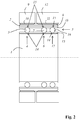
- FIG. 1 shows an embodiment of a voltage wave transmission according to the invention, comprising a wave generator 1, which is rotatably mounted in a radially flexible externally toothed sleeve 2.
- the wave generator 1 is rotatably supported relative to the radially flexible externally toothed sleeve 2 by means of a radially flexible rolling bearing 3, the rolling bearing having a first row of rolling elements 4 with first rolling elements 5 and a second axially spaced from the first row of rolling elements 4 second row of rolling elements 6 with second rolling elements 7
- the external toothing 8 of the radially flexible sleeve 2 is in meshing engagement with a first, rigid, internally toothed ring gear 9 on two tooth engagement points which circulate in operation and lie in the plane of the large vertical axis of the elliptical wave generator 1.
- the external toothing 8 is in meshing engagement with the internal toothing 11 of a second ring gear 12, likewise at two opposite points which rotate in operation.
- the radially flexible rolling bearing 3 has, as the component with which the first Rolling elements 5 of the first row of rolling elements 4 and the second rolling elements 7 of the second row of rolling elements 6 are in direct contact, an inner ring 13 and as a further component, with which the first rolling elements 5 of the first row of rolling elements 4 and the second rolling elements 7 of the second row of rolling elements 6 directly in contact stand, an outer ring 18.
- the inner ring 13 has two circumferential guide grooves 14 for the rolling elements 5, 7 of the two Wälz Eisenschn 4, 6.
- the outer ring 18 has similarly also two circumferential grooves 15 for the rolling elements 5, 7 of the two rows of rolling elements 4, 6.
- FIG. 2 shows another embodiment of a voltage wave transmission according to the invention, in which the first ring gear 9 is formed axially narrower than the second ring gear 12.
- the second ring gear 12 via the rolling elements 7 a second row of rolling elements 6 and additionally on the third rolling elements 16 of a third Rolling element 17 of the rolling bearing 3 supported.
- the radially flexible rolling bearing 3 as a component, with which the first rolling elements 5 of the first row of rolling elements 4 and the second rolling elements 7 of the second row of rolling elements 6 and the third rolling elements 16 of the third row of rolling elements 17 are in direct contact, has an inner ring with three circumferential guide grooves 14 for the rolling elements 5, 7, 16 of the individual rows of rolling elements 4, 6, 17.
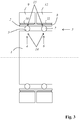
- FIG. 3 shows a third embodiment in which the rolling bearing 3 by the rolling elements 5, 7 of the plurality of Wälzschreibn 4, 6 and by the radially flexible sleeve 2, which has on its inner peripheral surface in each case a guide groove 15 for the rolling elements of each row of rolling elements 4, 6, and formed by the wave generator 1, which has on its outer circumferential surface in each case a guide groove 14 for the rolling elements 5, 7 of each row of rolling elements.
- no inner ring 13 and no outer ring 18 is present.
- the wave generator 1 and the radially flexible sleeve 2 function in this embodiment.
Landscapes
- Engineering & Computer Science (AREA)
- General Engineering & Computer Science (AREA)
- Mechanical Engineering (AREA)
- Retarders (AREA)
- Power Steering Mechanism (AREA)
- Rolling Contact Bearings (AREA)
Applications Claiming Priority (1)
| Application Number | Priority Date | Filing Date | Title |
|---|---|---|---|
| LU93010A LU93010B1 (de) | 2016-03-30 | 2016-03-30 | Spannungswellengetriebe |
Publications (1)
| Publication Number | Publication Date |
|---|---|
| EP3225881A1 true EP3225881A1 (de) | 2017-10-04 |
Family
ID=55802412
Family Applications (1)
| Application Number | Title | Priority Date | Filing Date |
|---|---|---|---|
| EP17163621.0A Pending EP3225881A1 (de) | 2016-03-30 | 2017-03-29 | Spannungswellengetriebe |
Country Status (6)
| Country | Link |
|---|---|
| US (1) | US10801599B2 (enExample) |
| EP (1) | EP3225881A1 (enExample) |
| JP (1) | JP6912242B2 (enExample) |
| CN (1) | CN207178462U (enExample) |
| DE (1) | DE102017106712A1 (enExample) |
| LU (1) | LU93010B1 (enExample) |
Cited By (1)
| Publication number | Priority date | Publication date | Assignee | Title |
|---|---|---|---|---|
| EP4443022A1 (en) * | 2023-04-05 | 2024-10-09 | Goodrich Actuation Systems Limited | Gear system |
Families Citing this family (5)
| Publication number | Priority date | Publication date | Assignee | Title |
|---|---|---|---|---|
| JP6552571B2 (ja) * | 2017-09-29 | 2019-07-31 | 株式会社ハーモニック・ドライブ・システムズ | デュアルタイプの波動歯車装置 |
| CN110630717B (zh) * | 2019-08-30 | 2021-11-16 | 浙江来福谐波传动股份有限公司 | 一款高扭矩高刚性长寿命谐波减速器及其安装方法 |
| LU500057B1 (de) | 2021-04-19 | 2022-10-19 | Ovalo Gmbh | Spannungswellengetriebe |
| DE102021109838A1 (de) | 2021-04-19 | 2022-10-20 | Ovalo Gmbh | Spannungswellengetriebe |
| CN114370487B (zh) * | 2022-01-24 | 2023-12-12 | 王瑞松 | 谐波减速器及传动装置 |
Citations (7)
| Publication number | Priority date | Publication date | Assignee | Title |
|---|---|---|---|---|
| SU1525367A2 (ru) * | 1987-07-22 | 1989-11-30 | Харьковский авиационный институт им.Н.Е.Жуковского | Волнова зубчата передача А.И.Полетучего |
| US4909098A (en) * | 1983-12-29 | 1990-03-20 | Mitsubishi Denki Kabushiki Kaisha | Harmonic drive apparatus |
| WO2009157607A1 (en) * | 2008-06-24 | 2009-12-30 | Korea Institute Of Science And Technology | Harmonic drive using profile shifted gear |
| EP2184514A1 (de) * | 2008-10-30 | 2010-05-12 | Ovalo GmbH | Spannungswellengetriebe |
| WO2012060609A1 (ko) * | 2010-11-01 | 2012-05-10 | 주식회사 에스비비테크 | 조화감속기 |
| DE102011004074A1 (de) * | 2011-02-14 | 2012-08-16 | Schaeffler Technologies Gmbh & Co. Kg | Wellgetriebe mit steifigkeitsoptimiertem Wellgenerator |
| US20150049975A1 (en) * | 2013-08-14 | 2015-02-19 | Mao-Tu Lee | Speed-reduction transmission bearing |
Family Cites Families (6)
| Publication number | Priority date | Publication date | Assignee | Title |
|---|---|---|---|---|
| US3091979A (en) * | 1961-05-08 | 1963-06-04 | United Shoe Machinery Corp | Power transmission |
| US3469463A (en) * | 1967-11-06 | 1969-09-30 | United Shoe Machinery Corp | Frictional drive speed changer |
| US4601216A (en) * | 1982-06-18 | 1986-07-22 | Matsushita Electric Industrial Co., Ltd. | Reduction gear |
| JP2503027B2 (ja) * | 1987-09-21 | 1996-06-05 | 株式会社ハーモニック・ドライブ・システムズ | 撓みかみ合い式歯車装置 |
| DE19713245C2 (de) * | 1997-03-29 | 2001-02-15 | Mercedes Benz Lenkungen Gmbh | Kraftfahrzeug mit zumindest einem über wenigstens einen Bedienhebel in Form eines sogenannten Side-stick steuerbaren Teil |
| DE10194857D2 (de) * | 2000-11-07 | 2003-10-23 | Luk Lamellen & Kupplungsbau | Elektromotorstellglied für Getriebe |
-
2016
- 2016-03-30 LU LU93010A patent/LU93010B1/de active IP Right Grant
-
2017
- 2017-03-29 US US15/473,055 patent/US10801599B2/en active Active
- 2017-03-29 DE DE102017106712.4A patent/DE102017106712A1/de not_active Withdrawn
- 2017-03-29 EP EP17163621.0A patent/EP3225881A1/de active Pending
- 2017-03-30 CN CN201720328823.6U patent/CN207178462U/zh not_active Expired - Fee Related
- 2017-03-30 JP JP2017066597A patent/JP6912242B2/ja active Active
Patent Citations (8)
| Publication number | Priority date | Publication date | Assignee | Title |
|---|---|---|---|---|
| US4909098A (en) * | 1983-12-29 | 1990-03-20 | Mitsubishi Denki Kabushiki Kaisha | Harmonic drive apparatus |
| SU1525367A2 (ru) * | 1987-07-22 | 1989-11-30 | Харьковский авиационный институт им.Н.Е.Жуковского | Волнова зубчата передача А.И.Полетучего |
| WO2009157607A1 (en) * | 2008-06-24 | 2009-12-30 | Korea Institute Of Science And Technology | Harmonic drive using profile shifted gear |
| EP2184514A1 (de) * | 2008-10-30 | 2010-05-12 | Ovalo GmbH | Spannungswellengetriebe |
| EP2184514B1 (de) | 2008-10-30 | 2014-12-24 | Ovalo GmbH | Spannungswellengetriebe |
| WO2012060609A1 (ko) * | 2010-11-01 | 2012-05-10 | 주식회사 에스비비테크 | 조화감속기 |
| DE102011004074A1 (de) * | 2011-02-14 | 2012-08-16 | Schaeffler Technologies Gmbh & Co. Kg | Wellgetriebe mit steifigkeitsoptimiertem Wellgenerator |
| US20150049975A1 (en) * | 2013-08-14 | 2015-02-19 | Mao-Tu Lee | Speed-reduction transmission bearing |
Cited By (2)
| Publication number | Priority date | Publication date | Assignee | Title |
|---|---|---|---|---|
| EP4443022A1 (en) * | 2023-04-05 | 2024-10-09 | Goodrich Actuation Systems Limited | Gear system |
| US12442440B2 (en) | 2023-04-05 | 2025-10-14 | Goodrich Actuation Systems Limited | Gear system |
Also Published As
| Publication number | Publication date |
|---|---|
| US10801599B2 (en) | 2020-10-13 |
| CN207178462U (zh) | 2018-04-03 |
| US20170284527A1 (en) | 2017-10-05 |
| LU93010B1 (de) | 2017-10-23 |
| JP6912242B2 (ja) | 2021-08-04 |
| DE102017106712A1 (de) | 2017-10-05 |
| JP2017187172A (ja) | 2017-10-12 |
Similar Documents
| Publication | Publication Date | Title |
|---|---|---|
| EP3225881A1 (de) | Spannungswellengetriebe | |
| DE102007017757B4 (de) | Oszillierendes innen eingreifendes Planetengetriebesystem | |
| AT513613B1 (de) | Zahnradanordnung | |
| DE102019125310A1 (de) | Planetenwälzgetriebe | |
| DE102008053914A1 (de) | Wellengenerator für ein Spannungswellengetriebe sowie Spannungswellengetriebe | |
| WO2012120005A1 (de) | Planetengetriebe einer windkraftanlage | |
| EP2161478B1 (de) | Zahnradanordnung | |
| DE102018200056A1 (de) | Planetengetriebe | |
| DE10002026B4 (de) | Schrägverzahntes Zahnrad mit einem Loslager | |
| EP3230627A1 (de) | Stufenplanet | |
| DE102004004351B4 (de) | Umlaufgetriebe für eine Windenergieanlage | |
| EP4086477A1 (de) | Getriebe | |
| DE102014222771A1 (de) | Zahnrad sowie Zahnradpaarung mit dem Zahnrad | |
| EP3728897B1 (de) | Zahnradgetriebe | |
| DE102014214331A1 (de) | Planetengetriebe | |
| EP3892889A1 (de) | Spannungswellengetriebe | |
| DE102008063107A1 (de) | Differenzialgetriebe | |
| DE102009013038B4 (de) | Tripodegelenkrolle und Tripodegelenk | |
| DE102019111153A1 (de) | Aktuator für eine Hinterachslenkung eines Fahrzeugs sowie Hinterachslenkung mit einem solchen Aktuator | |
| WO2015083040A2 (de) | Planeten-schraubenrad-getriebe | |
| WO2023237143A1 (de) | Getriebevorrichtung mit einem spielfreien untersetzungsgetriebe | |
| DE102021104842A1 (de) | Gewindetrieb | |
| WO2017092748A1 (de) | Lageranordnung für einen stufenplaneten, sowie hiermit ausgestattetes umlaufrädergetriebe für eine kraftfahrzeugantriebseinheit | |
| DE2351830C2 (de) | Kugelschraubgetriebe | |
| DE102016220944A1 (de) | Wellgetriebe für eine Wellenverstellvorrichtung sowie Wellenverstellvorrichtung mit dem Wellgetriebe |
Legal Events
| Date | Code | Title | Description |
|---|---|---|---|
| PUAI | Public reference made under article 153(3) epc to a published international application that has entered the european phase |
Free format text: ORIGINAL CODE: 0009012 |
|
| STAA | Information on the status of an ep patent application or granted ep patent |
Free format text: STATUS: THE APPLICATION HAS BEEN PUBLISHED |
|
| AK | Designated contracting states |
Kind code of ref document: A1 Designated state(s): AL AT BE BG CH CY CZ DE DK EE ES FI FR GB GR HR HU IE IS IT LI LT LU LV MC MK MT NL NO PL PT RO RS SE SI SK SM TR |
|
| AX | Request for extension of the european patent |
Extension state: BA ME |
|
| STAA | Information on the status of an ep patent application or granted ep patent |
Free format text: STATUS: REQUEST FOR EXAMINATION WAS MADE |
|
| 17P | Request for examination filed |
Effective date: 20180326 |
|
| RBV | Designated contracting states (corrected) |
Designated state(s): AL AT BE BG CH CY CZ DE DK EE ES FI FR GB GR HR HU IE IS IT LI LT LU LV MC MK MT NL NO PL PT RO RS SE SI SK SM TR |
|
| STAA | Information on the status of an ep patent application or granted ep patent |
Free format text: STATUS: EXAMINATION IS IN PROGRESS |
|
| 17Q | First examination report despatched |
Effective date: 20190618 |