EP3223597B2 - Outil électroportatif, et en particulier sécateur électrique à dissipateur thermique - Google Patents
Outil électroportatif, et en particulier sécateur électrique à dissipateur thermique Download PDFInfo
- Publication number
- EP3223597B2 EP3223597B2 EP15804167.3A EP15804167A EP3223597B2 EP 3223597 B2 EP3223597 B2 EP 3223597B2 EP 15804167 A EP15804167 A EP 15804167A EP 3223597 B2 EP3223597 B2 EP 3223597B2
- Authority
- EP
- European Patent Office
- Prior art keywords
- motor
- portable electric
- tool according
- electric tool
- handle
- Prior art date
- Legal status (The legal status is an assumption and is not a legal conclusion. Google has not performed a legal analysis and makes no representation as to the accuracy of the status listed.)
- Active
Links
Images
Classifications
-
- A—HUMAN NECESSITIES
- A01—AGRICULTURE; FORESTRY; ANIMAL HUSBANDRY; HUNTING; TRAPPING; FISHING
- A01G—HORTICULTURE; CULTIVATION OF VEGETABLES, FLOWERS, RICE, FRUIT, VINES, HOPS OR SEAWEED; FORESTRY; WATERING
- A01G3/00—Cutting implements specially adapted for horticultural purposes; Delimbing standing trees
- A01G3/02—Secateurs; Flower or fruit shears
- A01G3/033—Secateurs; Flower or fruit shears having motor-driven blades
- A01G3/037—Secateurs; Flower or fruit shears having motor-driven blades the driving means being an electric motor
-
- A—HUMAN NECESSITIES
- A01—AGRICULTURE; FORESTRY; ANIMAL HUSBANDRY; HUNTING; TRAPPING; FISHING
- A01D—HARVESTING; MOWING
- A01D46/00—Picking of fruits, vegetables, hops, or the like; Devices for shaking trees or shrubs
- A01D46/24—Devices for picking apples or like fruit
- A01D46/253—Portable motorised fruit pickers
-
- B—PERFORMING OPERATIONS; TRANSPORTING
- B26—HAND CUTTING TOOLS; CUTTING; SEVERING
- B26B—HAND-HELD CUTTING TOOLS NOT OTHERWISE PROVIDED FOR
- B26B15/00—Hand-held shears with motor-driven blades
-
- A—HUMAN NECESSITIES
- A01—AGRICULTURE; FORESTRY; ANIMAL HUSBANDRY; HUNTING; TRAPPING; FISHING
- A01G—HORTICULTURE; CULTIVATION OF VEGETABLES, FLOWERS, RICE, FRUIT, VINES, HOPS OR SEAWEED; FORESTRY; WATERING
- A01G3/00—Cutting implements specially adapted for horticultural purposes; Delimbing standing trees
- A01G3/02—Secateurs; Flower or fruit shears
- A01G3/033—Secateurs; Flower or fruit shears having motor-driven blades
-
- F—MECHANICAL ENGINEERING; LIGHTING; HEATING; WEAPONS; BLASTING
- F28—HEAT EXCHANGE IN GENERAL
- F28D—HEAT-EXCHANGE APPARATUS, NOT PROVIDED FOR IN ANOTHER SUBCLASS, IN WHICH THE HEAT-EXCHANGE MEDIA DO NOT COME INTO DIRECT CONTACT
- F28D21/00—Heat-exchange apparatus not covered by any of the groups F28D1/00 - F28D20/00
- F28D2021/0019—Other heat exchangers for particular applications; Heat exchange systems not otherwise provided for
- F28D2021/0028—Other heat exchangers for particular applications; Heat exchange systems not otherwise provided for for cooling heat generating elements, e.g. for cooling electronic components or electric devices
- F28D2021/0029—Heat sinks
-
- F—MECHANICAL ENGINEERING; LIGHTING; HEATING; WEAPONS; BLASTING
- F28—HEAT EXCHANGE IN GENERAL
- F28F—DETAILS OF HEAT-EXCHANGE AND HEAT-TRANSFER APPARATUS, OF GENERAL APPLICATION
- F28F2215/00—Fins
Definitions
- the present invention relates to a portable electric tool and in particular to an electric motor pruner which can be used for pruning and harvesting work, and in particular for pruning vines and fruit trees. It relates in particular to a pruner provided with a remote electrical power source, for example, a battery power source that can be worn on the belt or on the back.
- a remote electrical power source for example, a battery power source that can be worn on the belt or on the back.
- the invention can also be implemented for pruning shears with an integrated power source. More generally, the invention relates to portable power tools, and in particular tools having a plastic or composite material shell.
- Document D1 shows a pruner having a casing, in the form of a hollow body, part of which forms a handle, and inside which are housed in particular an electric motor and a transmission which connects the motor to a moving blade.
- the main function of the transmission is to communicate the movement of the motor, rotary, to a movable blade which is pivotally mounted on the housing.
- the mobile blade can pivot from an open position to a closed position on a fixed blade.
- the transmission comprises various components such as a reducer, connected to the motor shaft, a ball nut screw mechanism, mounted at the output of the reducer to convert the rotational movement of the motor into a translational movement, then connecting rods which connect a nut of the ball screw-nut mechanism to a cam of the movable blade.
- the electric motor is powered by a remote power source comprising an electric storage battery.
- a remote power source comprising an electric storage battery.
- the remote power source can be worn in particular on the belt or on the back. It is then connected to the shears by an appropriate power cable.
- the use of a remote power supply not only makes it possible to increase the autonomy of use of the pruning shears but also makes it possible to increase the power of the motor, in comparison with tools with an integrated battery.
- the electrical power consumed by the motor is more or less high.
- the electrical power absorbed is, for example, high in the case of pruning fruit trees or for pruning vine shoots of large section. It can reach peak values of the order of a kilowatt.
- the dissipated heat ends up heating the handle of the tool unacceptably.
- the housing materials are preferably light and comfortable materials for gripping the tool such as plastic materials which do not promote the dissipation of heat.
- the user's hand on the handle of the tool, and therefore on the housing, also constitutes a barrier to the evacuation of heat. All these factors contribute to increasing the temperature of the tool, and in particular of its handle, and make its use uncomfortable.
- a first reason is a particularly compact construction. Indeed, a part of the casing forming the handle of the shears is dimensioned so as to be able to be easily held by the hand. Thus the space available in the housing is limited. The same goes for the organs which are housed therein, and in particular the engine and its transmission which generate and transmit the power necessary for the operation of the tool.
- a second reason is related to requirements for comfort in gripping the tool, and lightness. These requirements are intended to limit user fatigue likely to use the tool for several hours. On the other hand, they dictate a choice of materials for the production of the casing.
- the object of the invention is to obviate the difficulties mentioned above and to propose a pruning shear with improved thermal comfort for the user's hand, despite intensive use.
- One aim is in particular to provide a pruning shear having a structure which greatly limits the heating of the handle.
- a goal is also to offer such a pruner allowing improved assembly and a particularly solid and durable construction.
- the invention proposes a portable electric pruner as defined by claim 1.
- the subsequent claims indicate particular embodiments.
- the intermediate casing can be made in one piece, or preferably in two adjacent removable parts, for example two half-shells.
- the term “transmission” is understood to mean all of the components which contribute to transmitting the movement of the engine to the cutting component.
- the transmission may include, for example, a reducer, a ball screw-nut mechanism, connecting rods, and a cam. It can be used to convert the rotational movement of the motor into a translational movement and the translational movement into a pivoting movement of a blade of the cutting member.
- the cutting member may in fact comprise at least one movable blade. It includes, for example, a movable blade pivoting relative to a fixed blade.
- the motor may include a stator, a rotor and rolling bearings supporting the rotation of the motor.
- the intermediate casing is in contact with the motor when it is in contact with a casing of the motor or directly with the stator, and/or the bearings of the motor.
- the intermediate casing can also be in thermal contact with transmission components. It is, for example, a reducer, mounted on the motor shaft, a ring gear of a reducer or a bearing of the transmission.
- a main function of the intermediate casing is to conduct a large part of the heat produced by various parts of the engine and/or the transmission towards the heat sink. This avoids overheating of the main housing and therefore of the handle.
- Another function of the intermediate casing can also be the assembly and the maintenance of the cohesion of different parts of the engine, and/or of the transmission.
- the latter can take the form of a casing or a sheath, in which are inserted the casing of a motor, a reduction gear and/or other elements of the transmission.
- the insertion of the different parts in the sheath is preferably adjusted to promote heat exchange.
- the intermediate casing can serve as a casing for the motor components, and/or a reduction gear coupled to the motor.
- the motor does not have its own envelope.
- the motor stator and bearings are housed directly in the intermediate casing.
- the intermediate casing can be designed to receive and maintain all the organs having a rotating part in rotation along the same axis as the motor shaft.
- the intermediate casing then preferably comprises several parts, for example two half-shells, which are assembled after the integration of the engine components and/or transmission components.
- the half-shells can be assembled by screwing. They can also be assembled at each of their ends by an elastic ring.
- the elastic ring of at least one of the ends can be, for example, an elastic ring of the “Circlips” type.
- the intermediate casing may also include a flange for assembly of a reduction gear on the motor. This is the case, in particular, when the reducer comprises a case of its own.
- the flange may be constituted by a part of the intermediate casing which extends relative to the motor and which surrounds the reduction gear.
- the intermediate casing can constitute a means of fixing the reducer to the motor or can directly constitute a common holding box for the components of the motor and of the reducer. It is thus possible to test or adjust the parameters of the assembly formed by the motor and the reduction gear before it is mounted in the main housing. These measures increase the manufacturing efficiency of the secados, and make it possible to eliminate defective elements before final assembly. They also make it possible to minimize the size of all the mechanical parts or at least to optimize the size of all the functional parts (motor, reducer, etc.) to optimize the mechanical performance of the tool.
- the intermediate casing which is a good heat conductor, is preferably made of a light metal such as aluminum or magnesium. It is housed in the main casing, and can extend in particular in a part of the main casing forming the handle of the shears.
- the main housing can be metallic or, preferably, of plastic material. It comprises, for example, a shell in two parts screwed on one another and dimensioned so as to receive and hold the internal components of the pruner and in particular the intermediate casing.
- the main housing also has a handle portion. This may be provided, where appropriate, with a control member such as a trigger.
- the heat sink is connected to the intermediate casing. It can be attached to the intermediate casing or be made in one piece with the intermediate casing.
- part of the dissipator can be formed on each of these half-shells.
- each half-shell can be provided with a heatsink fin. The heatsink protrudes outside the main housing when the intermediate housing is mounted in the main housing.
- the heat collected by the intermediate casing is transmitted by conduction to the dissipator. It is then dissipated outside the shears by radiation or by convection in contact with the ambient air.
- the heat can also be dissipated by conduction in other external organs of the shears, such as a guard.
- Several heatsinks, or a multi-part heatsink can be provided.
- the main housing thus has one or more passages for the dissipator. It may in particular have openings, for example slots, through which extend two fins of the dissipator.
- the dissipator is preferably provided in a part of the pruner which is not used as a handle. It is provided, for example, at one end of the handle. It can then constitute a guard or part of the guard, that is to say a mechanical protection for the hand of the user.
- the pruner may be provided with a guard extending along the handle and forming a bridge around the trigger.
- the heatsink can be used as a means of fixing the guard.
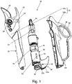
- the figure 1 shows a secateur 10 with a main casing 12 forming a handle 14.
- the main casing 12 preferably made of plastic material, or of a composite material, comprises an upper shell 12a and a lower shell 12b assembled by screwing onto the upper shell 12a.
- the main housing also serves to fix the cutting device.
- a fixing lug for a fixed blade 20 is screwed onto the upper shell.
- the casing also has the function of receiving and maintaining the organs of the pruner. It thus absorbs the forces of the cutting member and the forces generated by the internal organs.
- a motor 30, a planetary reduction gear 32 and a ball screw-nut mechanism 34 Inside the main casing 12 are notably housed a motor 30, a planetary reduction gear 32 and a ball screw-nut mechanism 34.
- the ball screw-nut mechanism 34 transforms the rotational movement of the motor into a movement of translation. It is connected by rods 36 to a cam 22 of a movable blade 24. The cam is moved by the rods and causes the movable blade 24 to pivot around a pivot 26 which connects it to the fixed blade 20.
- the movable blade 24 can in particular pivot from a rest position, open, to a closed position on the fixed blade, and vice versa.
- the movement of the blade is controlled by a trigger 16 provided at the front of the handle 14.
- the trigger 16 is associated with a position sensor and an electronic card configured to generate commands for the motor.
- the motor and the reduction gear are mounted in an intermediate casing 40.
- the intermediate casing comprises a first part 42 fitted to the motor, and in thermal contact with the motor.
- the first part 42 can be formed, for example, in the manner of a sleeve in which the motor is received with an interference fit.
- a second part 44 of the intermediate casing serves as a flange for fixing the reducer 32 to the motor.
- the second part 44 of the intermediate casing can also be formed in the manner of a sheath - for receiving the reducer.
- the reducer may not be received in the intermediate casing.
- the assembly formed by the motor and the reduction gear it is advantageous for the assembly formed by the motor and the reduction gear to be mounted in the intermediate casing. This is then used not only as a heat sink, but also as a fixing to hold the reduction gear on the motor.
- the motor 30 may comprise a casing which is specific to it and which is inserted into the first part 42 of the intermediate casing.
- the intermediate casing can also serve as a casing or support for the components constituting the motor and/or the reduction gear. This other possibility is described with reference to the figure 2 .
- the intermediate casing 40 is provided with a heat sink 50.
- the heat sink 50 comprises two cooling fins 52a, 52b, which project outside of the main casing 12 through suitable cutouts.
- the fins of the dissipator are formed at one end of the main casing, or of the tool body, opposite the end which carries the blades 20, 24 of the cutting member.
- the main function of the fins is a cooling function.
- the fins in fact favor the dissipation of the thermal energy produced by the motor and/or the reducer, and transmitted to the intermediate casing.
- the dissipation of thermal energy in the cooling fins 52a, 52b reduces the temperature inside the main casing 12 and limits the overheating of the handle 14.
- the cooling fins 52a, 52b, located at the rear of the handle, have a curved shape in the direction of the handle with a radius of curvature adapted to the hand of a user.
- the dissipator 50 also constitutes a first protective guard for the handle and more precisely for the hand of a user holding the handle.
- a second guard 54 extends the first guard formed by the heat sink 50 as far as the front part of the pruner receiving the cutting member.
- the second guard 54 can be made of metal or plastic. It runs along the handle 14 and forms a trigger guard 56 of the trigger 16.
- the second guard 54 is attached to the main housing 12 forward of the trigger 16. It is also attached to the heatsink 50 by means of a stud 58.
- the use of the heatsink as a fixing element for the guard provides a solid anchorage of the latter and contributes to the general solidity of the shears.
- a connector 60 is located at the rear of the pruner close to the motor 30. It makes it possible to connect the pruner 10 to a remote electric power supply source, by means of a power cable.
- the electrical energy supply source for example an accumulator battery, as well as the cable, are not represented on the figure 1 .
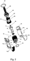
- the picture 2 shows a particular embodiment of the intermediate casing and of a motor-reduction unit housed in the intermediate casing 40.
- the crankcase 40 of the figure 2 takes the form of two half-shells 40a, 40b which serve directly as a casing for the organs of the motor 30 and of the reducer 32.
- a first part 42 of the intermediate casing is designed to house a stator 64 of the motor.
- stator 64 pins 62 which are the pins of the connector 60 mentioned with reference to the figure 1 .
- the second part 44 of the intermediate casing 40 no longer simply serves as a flange for fixing a reduction gear, as in the figure 1 , but serves as a housing for the reducer components.
- a ring gear 80 of the reducer is directly housed and fixed in the second part 44 of the intermediate casing.
- the reduction gear does not have its own casing but its components are directly received in the intermediate casing.
- the reducer comprises three satellites 82, rolling in the crown 80.
- the satellites 82 received on a planet carrier 84, are driven in rotation by a pinion 68 integral with the shaft of the rotor 66.
- the planet carrier 84 is mounted on a screw 86, coaxial with the motor shaft, which is part of the screw-ball nut mechanism mentioned with reference to the figure 1 .
- the two half-shells 40a, 40b of the intermediate casing are assembled by means of a first elastic ring 90, received on a shoulder 91 of the half-shells, and by means of a second elastic ring 92 received in a groove 93 of the half-shells. -shells.
- the second ring is of the “Circlips” type.
- each half-shell 40a, 40b is formed in one piece respectively with one of the fins 52a, 52b of the heat sink.
Landscapes
- Life Sciences & Earth Sciences (AREA)
- Forests & Forestry (AREA)
- Environmental Sciences (AREA)
- Biodiversity & Conservation Biology (AREA)
- Ecology (AREA)
- Engineering & Computer Science (AREA)
- Mechanical Engineering (AREA)
- Scissors And Nippers (AREA)
- Harvester Elements (AREA)
- Motor Or Generator Cooling System (AREA)
Description
- La présente invention concerne un outil électroportatif et en particulier un sécateur à moteur électrique utilisable pour des travaux de taille et de récolte, et notamment pour la taille de vignes et d'arbres fruitiers. Elle concerne notamment un sécateur pourvu d'une source d'alimentation électrique distante, par exemple, une source d'alimentation à batteries pouvant être portée à la ceinture ou dans le dos. L'invention peut aussi être mise en oeuvre pour les sécateurs à source d'alimentation intégrée. De manière plus générale, l'invention concerne des outils électroportatifs, et en particulier des outils ayant une coque en matière plastique ou composite.
- Les documents D1, D2, D3 et D4 dont les références sont précisées à la fin de la description, décrivent des sécateurs utilisables pour des travaux de récolte et de taille.
- Le document D1 montre un sécateur présentant un carter, sous la forme d'un corps évidé, dont une partie forme une poignée, et à l'intérieur duquel sont logés notamment un moteur électrique et une transmission qui relie le moteur à une lame mobile. La transmission a pour fonction essentielle de communiquer le mouvement du moteur, rotatif, à une lame mobile qui est montée pivotante sur le carter. La lame mobile peut pivoter d'une position ouverte à une position refermée sur une lame fixe.
- La transmission comporte différents organes tels qu'un réducteur, relié à l'arbre du moteur, un mécanisme de vis écrou à bille, monté à la sortie du réducteur pour convertir le mouvement de rotation du moteur en un mouvement de translation, puis des biellettes qui relient une noix du mécanisme de vis-écrou à billes à une came de la lame mobile.
- Le moteur électrique est alimenté par une source d'alimentation distante comprenant une batterie d'accumulateurs électriques. Comme le montre le document D2, la source d'alimentation distante peut être portée notamment à la ceinture ou au dos. Elle est alors reliée au sécateur par un câble d'alimentation approprié.
- L'utilisation d'une alimentation distante permet non seulement d'augmenter l'autonomie d'utilisation du sécateur mais permet également d'augmenter la puissance du moteur, en comparaison avec des outils à batterie intégrée.
- Selon le type d'utilisation du sécateur, la puissance électrique consommée par le moteur est plus ou moins élevée. La puissance électrique absorbée est par exemple élevée dans le cas de la taille d'arbres fruitiers ou pour la taille de sarments de vigne de section importante. Elle peut atteindre des valeurs de crête de l'ordre du kilowatt.
- En dépit d'un rendement élevé des sécateurs, et de frottements particulièrement réduits, une partie de la puissance électrique consommée par l'outil est inévitablement transformée en chaleur. Les principales sources de chaleur dans le sécateur sont le moteur, les paliers de son rotor et le réducteur de la transmission. Or, ces éléments se trouvent généralement logés dans une partie de l'outil qui forme sa poignée.
- Dans le cas d'une utilisation intensive et prolongée de l'outil, rendue possible par des sources d'alimentation de forte capacité, la chaleur dissipée finit par chauffer de manière inacceptable la poignée de l'outil. Ce phénomène est accentué par le choix des matériaux utilisés pour le carter. En effet, les matériaux du carter sont de préférence des matériaux légers et confortables pour la préhension de l'outil tels que des matières plastiques qui ne favorisent pas la dissipation de la chaleur. La main de l'utilisateur sur la poignée de l'outil, et donc sur le carter, constitue également une barrière à l'évacuation de la chaleur. Tous ces facteurs contribuent à augmenter la température de l'outil, et en particulier de sa poignée, et rendent son utilisation inconfortable.
- Le problème de la génération de chaleur n'est pas propre aux sécateurs mais se pose de manière particulière pour ces outils. En effet, les possibilités de modification de la structure des sécateurs en vue d'un échauffement moindre sont limitées pour plusieurs raisons.
- Une première raison est une construction particulièrement compacte. En effet, une partie du carter formant la poignée du sécateur est dimensionnée de manière à pouvoir être aisément tenue par la main. Ainsi l'espace disponible dans le carter est limité. Il en va de même pour les organes qui y sont logés, et notamment le moteur et sa transmission qui génèrent et transmettent la puissance nécessaire au fonctionnement de l'outil.
- Une seconde raison est liée à des exigences de confort de la préhension de l'outil, et de légèreté. Ces exigences visent à limiter la fatigue de l'utilisateur susceptible d'utiliser l'outil pendant plusieurs heures. Elles dictent en revanche un choix de matériaux pour la réalisation du carter.
- Enfin, une troisième raison est liée à la nécessité d'un assemblage robuste et fiable des éléments de l'outil, tout en autorisant un démontage partiel, pour des opérations de maintenance ou de nettoyage.
- L'invention a pour but d'obvier aux difficultés mentionnées ci-dessus et de proposer un sécateur avec un confort thermique amélioré pour la main de l'utilisateur, en dépit d'un usage intensif.
- Un but est en particulier de proposer un sécateur disposant d'une structure limitant fortement l'échauffement de la poignée.
- Un but est aussi de proposer un tel sécateur autorisant un assemblage amélioré et une construction particulièrement solide et endurante.
- Pour atteindre ces buts, l'invention propose un sécateur électroportatif tel que défini par la revendication 1. Les revendications subséquentes indiquent des modes de réalisation particuliers.
- Le carter intermédiaire peut être réalisé d'une seule pièce, ou, de préférence en deux parties adjacentes démontables, par exemple deux demi-coques.
- On entend par transmission l'ensemble des organes qui contribuent à transmettre le mouvement du moteur à l'organe de coupe. La transmission peut comporter, par exemple, un réducteur, un mécanisme de vis-écrou à billes, des biellettes, et une came. Elle peut être utilisée pour convertir le mouvement de rotation du moteur, en un mouvement de translation et le mouvement de translation en un mouvement de pivotement d'une lame de l'organe de coupe.
- L'organe de coupe peut comporter en effet au moins une lame mobile. Il comprend, par exemple, une lame mobile pivotant par rapport à une lame fixe.
- Le moteur peut comporter un stator, un rotor et des paliers de roulement supportant la rotation du moteur.
- On considère que le carter intermédiaire est en contact avec le moteur lorsqu'il est en contact avec un boîtier du moteur ou directement avec le stator, et/ou les paliers du moteur.
- Le carter intermédiaire peut aussi être en contact thermique avec des organes de la transmission. Il s'agit, par exemple, d'un réducteur, monté sur l'arbre du moteur, d'une couronne d'un réducteur ou d'un palier de la transmission.
- Une fonction principale du carter intermédiaire est de conduire une grande partie de la chaleur produite par différents organes du moteur et/ou de la transmission vers le dissipateur thermique. Ceci évite un échauffement du carter principal et donc de la poignée.
- Une autre fonction du carter intermédiaire, peut aussi être l'assemblage et le maintien de la cohésion de différentes parties du moteur, et/ou de la transmission.
- Dans une réalisation très simple du carter intermédiaire, celui-ci peut se présenter comme un étui ou un fourreau, dans lequel sont insérés, le boîtier d'un moteur, un réducteur et/ou d'autres éléments de la transmission. L'insertion des différentes parties dans le fourreau est de préférence ajustée pour favoriser les échanges thermiques.
- Dans une autre réalisation, particulièrement compacte, le carter intermédiaire peut servir de boîtier pour les organes du moteur, et/ou d'un réducteur couplé au moteur. Dans ce cas, le moteur n'a pas d'enveloppe propre. Le stator et les paliers du moteur sont directement logés dans le carter intermédiaire. De manière générale le carter intermédiaire peut être conçu pour recevoir et maintenir tous les organes ayant une pièce tournante en rotation selon le même axe que l'arbre du moteur.
- Le carter intermédiaire comprend alors de préférence plusieurs parties, par exemple deux demi-coques, qui sont assemblées après l'intégration des organes du moteur et/ou d'organes de la transmission. Les demi-coques peuvent être assemblées par vissage. Elles peuvent aussi être assemblées à chacune de leur extrémité par un anneau élastique. L'anneau élastique d'au moins une des extrémités peut être, par exemple, un anneau élastique de type « Circlips ».
- Le carter intermédiaire peut encore comporter une bride pour un assemblage d'un réducteur sur le moteur. Ceci est le cas, notamment, lorsque le réducteur comprend un boîtier qui lui est propre. La bride peut être constituée par une partie du carter intermédiaire qui se prolonge par rapport au moteur et qui entoure le réducteur.
- Comme il ressort de ce qui précède, le carter intermédiaire peut constituer un moyen de fixation du réducteur sur le moteur ou peut constituer directement un boîtier de maintien commun pour des organes du moteur et du réducteur. Il est ainsi possible de tester ou de régler les paramètres de l'ensemble formé par le moteur et le réducteur avant son montage dans le carter principal. Ces mesures augmentent le rendement de fabrication du sécateur, et permettent d'éliminer les éléments défectueux avant l'assemblage final. Elles permettent aussi de minimiser l'encombrement de l'ensemble des pièces mécaniques ou tout au moins d'optimiser la taille de toutes les pièces fonctionnelles (moteur, réducteur, ...) pour optimiser les performances mécaniques de l'outil.
- Le carter intermédiaire, bon conducteur de la chaleur, est de préférence en un métal léger tel que l'aluminium ou le magnésium. Il est logé dans le carter principal, et peut s'étendre notamment dans une partie du carter principal formant la poignée du sécateur.
- Le carter principal peut être métallique ou, de préférence, en matière plastique. Il comprend, par exemple, une coque en deux parties vissées l'une sur l'autre et dimensionnées de manière à recevoir et maintenir les composants internes du sécateur et notamment le carter intermédiaire. Le carter principal présente également une partie formant poignée. Celle-ci peut être pourvue, le cas échéant, d'un organe de commande tel qu'une gâchette.
- Le dissipateur thermique est relié au carter intermédiaire. Il peut être rapporté sur le carter intermédiaire ou être fabriqué d'une seule pièce avec le carter intermédiaire. Lorsque le carter intermédiaire est lui-même formé de deux demi-coques assemblées, une partie du dissipateur peut être formée sur chacune de ces demi-coques. Par exemple, chaque demi-coque peut être pourvue d'une ailette du dissipateur. Le dissipateur fait saillie à l'extérieur du carter principal lorsque le carter intermédiaire est monté dans le carter principal.
- La chaleur recueillie par le carter intermédiaire est transmise par conduction vers le dissipateur. Elle est ensuite dissipée à l'extérieur du sécateur par rayonnement ou par convection au contact de l'air ambiant. La chaleur peut aussi être dissipée par conduction dans d'autres organes extérieurs du sécateur, tels qu'une garde. Plusieurs dissipateurs, ou un dissipateur en plusieurs parties peuvent être prévus. Le carter principal présente ainsi un ou plusieurs passages pour le dissipateur. Il peut notamment présenter des ajourages, par exemple des fentes, à travers lesquelles s'étendent deux ailettes du dissipateur.
- Le dissipateur est de préférence ménagé en une partie du sécateur qui n'est pas utilisée comme poignée. Il est ménagé, par exemple, en une extrémité de la poignée. Il peut alors constituer une garde ou une partie de garde, c'est-à-dire une protection mécanique pour la main de l'utilisateur.
- Le sécateur peut être pourvu d'une garde s'étendant le long de la poignée et formant un pontet autour de la gâchette. Dans ce cas, le dissipateur peut être utilisé comme un moyen de fixation de la garde.
- D'autres caractéristiques et avantages de l'invention ressortent de la description des figures qui suit. Cette description est donnée à titre d'illustration et non de limitation.
-
- La
figure 1 est un éclaté partiel d'un sécateur conforme à l'invention. - La
figure 2 est un éclaté d'un carter intermédiaire du sécateur de lafigure 1 et d'un ensemble moteur-réducteur qui y est logé. - La
figure 1 montre un sécateur 10 avec un carter principal 12 formant une poignée 14. Le carter principal 12, de préférence en matière plastique, ou en un matériau composite, comprend une coque supérieure 12a et une coque inférieure 12b assemblée par vissage sur la coque supérieure 12a. Outre la fonction de poignée, le carter principal sert aussi à la fixation de l'organe de coupe. Par exemple, une patte de fixation d'une lame fixe 20 est vissée sur la coque supérieure. Le carter a encore pour fonction de recevoir et de maintenir les organes du sécateur. Il reprend ainsi les efforts de l'organe de coupe et les efforts générés par les organes internes. - A l'intérieur du carter principal 12 sont notamment logés un moteur 30, un réducteur à planétaire 32 et un mécanisme de vis-écrou à billes 34. Le mécanisme de vis-écrou à billes 34 transforme le mouvement de rotation du moteur en un mouvement de translation. Il est relié par des biellettes 36 à une came 22 d'une lame mobile 24. La came est mue par les biellettes et fait pivoter la lame mobile 24 autour d'un pivot 26 qui la relie à la lame fixe 20. La lame mobile 24 peut en particulier pivoter d'une position de repos, ouverte, vers une position refermée sur la lame fixe, et inversement. Le mouvement de la lame est commandé par une gâchette 16 ménagée à l'avant de la poignée 14.
- La gâchette 16 est associée à un capteur de position et à une carte électronique configurée pour générer des commandes pour le moteur.
- Sur la
figure 1 , le moteur et le réducteur sont montés dans un carter intermédiaire 40. Le carter intermédiaire comprend une première partie 42 ajustée au moteur, et en contact thermique avec le moteur. La première partie 42 peut être formée, par exemple, à la manière d'un fourreau dans lequel le moteur est reçu à ajustement serré. Une deuxième partie 44 du carter intermédiaire sert de bride de fixation du réducteur 32 sur le moteur. La deuxième partie 44 du carter intermédiaire peut également être formée à la manière d'un fourreau - pour la réception du réducteur. - Dans une version plus simple, le réducteur peut ne pas être reçu dans le carter intermédiaire. Toutefois, il est avantageux que l'ensemble formé par le moteur et le réducteur soit monté dans le carter intermédiaire. Celui-ci sert alors, non seulement de dissipateur thermique, mais aussi de fixation pour maintenir le réducteur sur le moteur. Le moteur 30 peut comporter un boîtier qui lui est propre et qui est inséré dans la première partie 42 du carter intermédiaire. Le carter intermédiaire peut encore servir de boîtier ou de support pour les organes constituant le moteur et/ou le réducteur. Cette autre possibilité est décrite en référence à la
figure 2 . - Comme évoqué précédemment, il est possible, grâce au carter intermédiaire, de tester l'ensemble moteur-réducteur avant son assemblage avec les autres organes du sécateur et avant son montage dans le carter principal.
- Par retour à la
figure 1 , on peut observer que le carter intermédiaire 40 est pourvu d'un dissipateur thermique 50. Le dissipateur thermique 50 comprend deux ailettes de refroidissement 52a, 52b, qui font saillie à l'extérieur du carter principal 12 à travers des ajourages adaptés. Les ailettes du dissipateur sont ménagées en une extrémité du carter principal, ou du corps d'outil, opposée à l'extrémité qui porte les lames 20, 24 de l'organe de coupe. La fonction principale des ailettes est une fonction de refroidissement. Les ailettes favorisent en effet la dissipation de l'énergie thermique produite par le moteur et/ou le réducteur, et transmise à au carter intermédiaire. La dissipation de l'énergie thermique dans les ailettes de refroidissement 52a, 52b réduit la température à l'intérieur du carter principal 12 et limite l'échauffement de la poignée 14. - Les ailettes de refroidissement 52a, 52b, situées à l'arrière de la poignée, présentent une forme incurvée en direction de la poignée avec un rayon de courbure adapté à la main d'un utilisateur. Ainsi le dissipateur 50 constitue également une première garde de protection de la poignée et plus précisément de la main d'un utilisateur tenant la poignée. Une deuxième garde 54, prolonge la première garde formée par le dissipateur thermique 50 jusqu'à la partie avant du sécateur recevant l'organe de coupe. La deuxième garde 54 peut être en métal ou en matière plastique. Elle longe la poignée 14 et forme un pontet 56 de la gâchette 16.
- La deuxième garde 54 est fixée au carter principal 12 à l'avant de la gâchette 16. Elle est également fixée au dissipateur 50 au moyen d'un goujon 58. L'utilisation du dissipateur comme élément de fixation pour la garde procure un ancrage solide de cette dernière et participe à la solidité générale du sécateur.
- Un connecteur 60 se situe à l'arrière du sécateur à proximité du moteur 30. Il permet de relier le sécateur 10 à une source d'alimentation en énergie électrique distante, au moyen d'un câble d'alimentation. La source d'alimentation en énergie électrique, par exemple une batterie d'accumulateurs, de même que le câble, ne sont pas représentés sur la
figure 1 . - La
figure 2 montre une réalisation particulière du carter intermédiaire et d'un ensemble moteur-réducteur logé dans le carter intermédiaire 40. - Le carter 40 de la
figure 2 se présente sous la forme de deux demi-coques 40a, 40b qui servent directement de boîtier pour les organes du moteur 30 et du réducteur 32. En particulier une première partie 42 du carter intermédiaire est conçue pour loger un stator 64 du moteur. On peut observer à l'arrière du stator 64 des broches 62 qui sont les broches du connecteur 60 évoqué en référence à lafigure 1 . - Un rotor 66 du moteur, concentrique au stator 64, est monté sur des roulements 70, 72 qui sont reçus respectivement dans des logements correspondants 71, 73 du carter intermédiaire 40.
- De la même manière, la deuxième partie 44 du carter intermédiaire 40 ne sert plus simplement de bride de fixation d'un réducteur, comme dans la
figure 1 , mais sert de boîtier pour les organes du réducteur. En particulier, une couronne 80 du réducteur est directement logée et fixée dans la deuxième partie 44 du carter intermédiaire. En d'autres termes, le réducteur n'a pas de boîtier propre mais ses organes sont directement reçus dans le carter intermédiaire. - Dans l'exemple de la
figure 2 , le réducteur comprend trois satellites 82, roulant dans la couronne 80. Les satellites 82, reçus sur un porte satellite 84, sont entraînés en rotation par un pignon 68 solidaire de l'arbre du rotor 66. Le porte satellite 84 est monté sur une vis 86, coaxiale à l'arbre du moteur, qui fait partie du mécanisme de vis-écrou à billes évoqué en référence à lafigure 1 . - Les deux demi-coques 40a, 40b du carter intermédiaires sont assemblées au moyen d'un premier anneau élastique 90, reçu sur un épaulement 91 des demi-coques, et au moyen d'un deuxième anneau élastique 92 reçu dans une gorge 93 des demi-coques. Le deuxième anneau est de type « Circlips ».
- On peut encore observer que chaque demi-coque 40a, 40b est formée d'une seule pièce respectivement avec l'une des ailettes 52a, 52b du dissipateur thermique.
-
- D1 :
FR 2614568 - D2 :
G8614677 - D3 :
EP 2156732 - D4 :
CN 203537937 U .
Claims (14)
- Sécateur électroportatif comprenant un moteur électrique (30), un organe de coupe (20, 24), et une transmission (32, 34, 36) reliant le moteur électrique à l'organe de coupe, le moteur et la transmission étant logés dans un carter principal (12) formant une poignée (14),le sécateur électroportatif comprenant également :• un carter intermédiaire (40, 42, 44) en un matériau conducteur thermique, logé dans le carter principal (12) et s'étendant à l'intérieur de la poignée (14),• au moins un dissipateur thermique (50), relié au carter intermédiaire (40, 42, 44), et faisant saillie à l'extérieur du carter principal (12),le sécateur électroportatif étant caractérisé en ce que :• le carter principal (12), outre la fonction de poignée (14), sert aussi à la fixation de l'organe de coupe (20, 24),• le carter intermédiaire (40, 42, 44) est en contact thermique avec le moteur électrique (30).
- Outil électroportatif selon la revendication 1, dans lequel le carter intermédiaire (40, 42, 44) comprend deux parties (40a, 40b) adjacentes et démontables.
- Outil électroportatif selon la revendication 1, dans lequel le carter intermédiaire (40, 42, 44) est réalisé d'une seule pièce.
- Outil électroportatif selon l'une des revendications précédentes, dans lequel le carter intermédiaire (40) est en outre en contact thermique avec au moins un organe de la transmission.
- Outil électroportatif selon l'une des revendications précédentes, dans lequel la transmission comprend un réducteur (32) et dans lequel le carter intermédiaire (40) est en contact thermique avec le réducteur (32).
- Outil électroportatif selon la revendication 5, dans lequel le réducteur (32) comprend une couronne (80) directement fixée dans le carter intermédiaire (40).
- Outil électroportatif selon l'une des revendications précédentes, dans lequel le carter intermédiaire (40) comprend une bride (44) pour un assemblage du réducteur sur le moteur.
- Outil électroportatif selon l'une des revendications précédentes, dans lequel le moteur comprend un stator (64) et des paliers de roulement (70, 72), le stator et les paliers de roulement étant directement fixés dans le carter intermédiaire (40).
- Outil électroportatif selon l'une des revendications précédentes, dans lequel le moteur présente un boîtier inséré dans le carter intermédiaire.
- Outil électroportatif selon l'une des revendications précédentes dans lequel le dissipateur (50) est formé d'une seule pièce avec le carter intermédiaire (40).
- Outil électroportatif selon l'une des revendications précédentes, dans lequel l'organe de coupe (20, 24) est solidaire d'une première extrémité du carter principal (12) et dans lequel le dissipateur (50) fait saillie à l'extérieur du carter principal en une deuxième extrémité du carter principal sensiblement opposée à la première extrémité.
- Outil électroportatif selon l'une des revendications précédentes dans lequel le dissipateur thermique (50) présente deux ailettes (52a, 52b).
- Outil électroportatif selon la revendication 10, dans lequel la poignée (14) est pourvue d'une garde (54), la garde étant reliée au dissipateur thermique (50).
- Outil électroportatif selon la revendication 10, dans lequel le dissipateur thermique (50) est ménagé à proximité de la poignée (14) du sécateur pour former une garde de protection de la poignée.
Applications Claiming Priority (2)
| Application Number | Priority Date | Filing Date | Title |
|---|---|---|---|
| FR1461405A FR3028716B1 (fr) | 2014-11-25 | 2014-11-25 | Outil electroportatif, et en particulier secateur electrique a dissipateur thermique. |
| PCT/FR2015/052964 WO2016083695A1 (fr) | 2014-11-25 | 2015-11-03 | Outil électroportatif, et en particulier sécateur électrique à dissipateur thermique |
Publications (3)
| Publication Number | Publication Date |
|---|---|
| EP3223597A1 EP3223597A1 (fr) | 2017-10-04 |
| EP3223597B1 EP3223597B1 (fr) | 2019-01-09 |
| EP3223597B2 true EP3223597B2 (fr) | 2022-10-26 |
Family
ID=52392090
Family Applications (1)
| Application Number | Title | Priority Date | Filing Date |
|---|---|---|---|
| EP15804167.3A Active EP3223597B2 (fr) | 2014-11-25 | 2015-11-03 | Outil électroportatif, et en particulier sécateur électrique à dissipateur thermique |
Country Status (9)
| Country | Link |
|---|---|
| US (1) | US10091947B2 (fr) |
| EP (1) | EP3223597B2 (fr) |
| JP (1) | JP6557350B2 (fr) |
| KR (1) | KR102516682B1 (fr) |
| CN (1) | CN106998656B (fr) |
| BR (1) | BR112017007573B1 (fr) |
| ES (1) | ES2718942T5 (fr) |
| FR (1) | FR3028716B1 (fr) |
| WO (1) | WO2016083695A1 (fr) |
Families Citing this family (14)
| Publication number | Priority date | Publication date | Assignee | Title |
|---|---|---|---|---|
| JP2020069259A (ja) * | 2018-11-01 | 2020-05-07 | 株式会社マキタ | 充電式シャー |
| FR3106953B1 (fr) | 2020-02-12 | 2022-04-01 | Innovation Fabrication Commercialisation Infaco | Sécateur à ventilation forcée |
| JP6830558B1 (ja) * | 2020-04-21 | 2021-02-17 | アルスコーポレーション株式会社 | 電動剪定鋏 |
| CN111791194B (zh) * | 2020-06-30 | 2025-09-09 | 浙江动一新能源动力科技股份有限公司 | 一种电动工具壳体及电动工具 |
| CN111730644A (zh) * | 2020-07-22 | 2020-10-02 | 惠州果颗科技有限公司 | 一种便于散热的改进型电动剪刀 |
| WO2022036216A1 (fr) * | 2020-08-13 | 2022-02-17 | Saudi Arabian Oil Company | Procédé de déploiement d'une injection de mousse de dioxyde de carbone dans un gisement de pétrole |
| US12202155B2 (en) | 2020-09-10 | 2025-01-21 | Techtronic Cordless Gp | Blade change mechanism for power tool |
| AU2021104983A4 (en) | 2020-09-10 | 2021-09-30 | Techtronic Cordless Gp | Blade replacement mechanism of electric instrument |
| KR102524087B1 (ko) * | 2020-12-11 | 2023-04-19 | 심상용 | 순치기용 자동 절단장치 |
| CN112514673A (zh) * | 2020-12-24 | 2021-03-19 | 东莞市嘉航实业有限公司 | 电剪刀刀片双向驱动机构及电动剪刀 |
| USD1000243S1 (en) * | 2021-07-09 | 2023-10-03 | Suzhou Ailixi Brushless Motor Co., Ltd. | Electric scissors |
| WO2023065028A1 (fr) | 2021-10-22 | 2023-04-27 | Ring Rescue Inc. | Coupe-bague destiné à couper en toute sécurité une bague coincée sur un appendice |
| USD1003137S1 (en) * | 2022-03-25 | 2023-10-31 | Innovation Fabrication Commercialisation Infaco | Hedge trimmer |
| USD1089340S1 (en) | 2023-06-22 | 2025-08-19 | Ring Rescue Inc. | Ring cutter |
Citations (5)
| Publication number | Priority date | Publication date | Assignee | Title |
|---|---|---|---|---|
| EP2036681A1 (fr) † | 2007-09-14 | 2009-03-18 | Alexander Kipfelsberger | Visseuse, en particulier visseuse de court-circuit |
| US20110001368A1 (en) † | 2009-07-03 | 2011-01-06 | James Ching Sik Lau | Power tool |
| US20110006621A1 (en) † | 2009-07-08 | 2011-01-13 | Johnson Electric S.A. | Power tool |
| WO2013093619A2 (fr) † | 2011-12-19 | 2013-06-27 | Carine Elen | Outil motorisé de nettoyage, frottage et polissage |
| EP2659764A1 (fr) † | 2012-05-04 | 2013-11-06 | Felco SA | Outil électroportatif et procédé d'assemblage d'un tel outil électroportatif |
Family Cites Families (33)
| Publication number | Priority date | Publication date | Assignee | Title |
|---|---|---|---|---|
| US1755511A (en) * | 1928-05-28 | 1930-04-22 | Frank A Miller | Power shears |
| US1758485A (en) * | 1929-02-28 | 1930-05-13 | Frank D Vartanian | Power shears |
| US2020567A (en) * | 1934-08-10 | 1935-11-12 | Noske Rudolf | Mechanical movement shears |
| US2287347A (en) * | 1941-05-06 | 1942-06-23 | Daniel F Young | Electric scissors |
| US2621404A (en) * | 1952-02-21 | 1952-12-16 | Carl M Koons | Motor-driven shear means |
| US3971132A (en) * | 1971-09-17 | 1976-07-27 | Rockwell International Corporation | Saber saw |
| US3945120A (en) * | 1974-04-25 | 1976-03-23 | Milwaukee Electric Tool Corporation | Vibration dampening and heat sink mechanism for a reciprocating power saw |
| DE8614677U1 (de) | 1986-05-30 | 1986-07-17 | NIKO Nippert Maschinenbau, 77815 Bühl | Maschinelle Handschere, insbesondere für die Landwirtschaft |
| FR2614568B1 (fr) | 1987-04-28 | 1989-07-28 | Pellenc & Motte | Outil electrique portable a asservissement en position |
| US6634107B2 (en) * | 1999-03-12 | 2003-10-21 | Hitachi Koki Co., Ltd. | Cutting mechanism for a saber saw |
| AU2197002A (en) * | 2000-12-05 | 2002-06-18 | Hispaes S A | Portable, motor-powered shears |
| US6646341B2 (en) * | 2002-02-20 | 2003-11-11 | Hewelett-Packard Development Company, L.P. | Heat sink apparatus utilizing the heat sink shroud to dissipate heat |
| DE202005001674U1 (de) * | 2005-02-03 | 2005-04-14 | Kmk Kunststoff- Und Montagetechnik Gmbh | Handgeführtes Gartengerät mit einem elektromotorischen Antriebssystem mit Mehrphasenmotor |
| JP5034348B2 (ja) | 2006-07-20 | 2012-09-26 | マックス株式会社 | 電動式ハサミ |
| US20080173138A1 (en) * | 2006-08-15 | 2008-07-24 | Dayton Douglas C | Systems and methods of a vacuum cup bulb changer power tool system with interchangeable functional attachments |
| AT504324B8 (de) * | 2007-04-20 | 2008-09-15 | Strube Karl | Elektrische schere |
| US20090014251A1 (en) * | 2007-07-11 | 2009-01-15 | Mccracken Oliver Wendell | Positioning system |
| US20090049694A1 (en) * | 2007-08-21 | 2009-02-26 | Gary Jay Morris | Electric shaver apparatus with actively cooled surface |
| FR2935175B1 (fr) * | 2008-08-22 | 2011-02-11 | Pellenc Sa | Dispositif permettant de determiner la position relative entre deux organes dont l'un au moins est mobile, et machines et appareils en faisant application |
| FR2935106B1 (fr) * | 2008-08-22 | 2010-09-17 | Pellenc Sa | Outil electroportatif a commande par gachette |
| FR2935284B1 (fr) * | 2008-08-26 | 2010-09-17 | Pellenc Sa | Outil electroportatif mecanise a deux manches |
| KR101132328B1 (ko) * | 2009-03-23 | 2012-04-05 | 로아텍 주식회사 | 방아쇠가 구비된 전동 전지가위 |
| CN201493868U (zh) * | 2009-09-08 | 2010-06-02 | 南京德朔实业有限公司 | 电动剪刀 |
| US20110214292A1 (en) * | 2010-03-02 | 2011-09-08 | Moon Heh | Electric scissors having a replaceable blade |
| FR2957834B1 (fr) | 2010-03-24 | 2012-03-09 | Infaco | Dispositif de controle positionnel de deux elements l'un par rapport a l'autre tel que lames d'outils de coupe du genre secateur et outil de coupe le comportant |
| US20130263456A1 (en) * | 2010-12-15 | 2013-10-10 | Positec Power Tools (Suzhou) Co., Ltd. | Cutting accessory and an oscillating power tool using the cutting accessory |
| US20120174416A1 (en) * | 2011-01-07 | 2012-07-12 | Ci, Llc | Electric pruning device |
| JP5632884B2 (ja) * | 2012-08-15 | 2014-11-26 | 株式会社マキタ | 動力工具 |
| JP2013166244A (ja) | 2013-04-01 | 2013-08-29 | Max Co Ltd | 電動工具 |
| CN203537937U (zh) * | 2013-09-26 | 2014-04-16 | 宁波市镇海长城汽车摩托车部件厂 | 一种新型电动果树修枝剪 |
| US9796099B2 (en) * | 2014-04-08 | 2017-10-24 | Terry Sandefur | Cutting apparatus |
| US20150313089A1 (en) * | 2014-04-30 | 2015-11-05 | Remo Francesco CECCHI | Cutting system |
| CN104094782A (zh) * | 2014-06-20 | 2014-10-15 | 宁波大叶园林设备有限公司 | 一种含冷却护套以防护电池的锂电链锯 |
-
2014
- 2014-11-25 FR FR1461405A patent/FR3028716B1/fr not_active Expired - Fee Related
-
2015
- 2015-11-03 KR KR1020177017620A patent/KR102516682B1/ko active Active
- 2015-11-03 ES ES15804167T patent/ES2718942T5/es active Active
- 2015-11-03 EP EP15804167.3A patent/EP3223597B2/fr active Active
- 2015-11-03 CN CN201580063718.8A patent/CN106998656B/zh active Active
- 2015-11-03 WO PCT/FR2015/052964 patent/WO2016083695A1/fr not_active Ceased
- 2015-11-03 JP JP2017546047A patent/JP6557350B2/ja active Active
- 2015-11-03 BR BR112017007573-3A patent/BR112017007573B1/pt not_active IP Right Cessation
- 2015-11-03 US US15/513,292 patent/US10091947B2/en active Active
Patent Citations (5)
| Publication number | Priority date | Publication date | Assignee | Title |
|---|---|---|---|---|
| EP2036681A1 (fr) † | 2007-09-14 | 2009-03-18 | Alexander Kipfelsberger | Visseuse, en particulier visseuse de court-circuit |
| US20110001368A1 (en) † | 2009-07-03 | 2011-01-06 | James Ching Sik Lau | Power tool |
| US20110006621A1 (en) † | 2009-07-08 | 2011-01-13 | Johnson Electric S.A. | Power tool |
| WO2013093619A2 (fr) † | 2011-12-19 | 2013-06-27 | Carine Elen | Outil motorisé de nettoyage, frottage et polissage |
| EP2659764A1 (fr) † | 2012-05-04 | 2013-11-06 | Felco SA | Outil électroportatif et procédé d'assemblage d'un tel outil électroportatif |
Non-Patent Citations (1)
| Title |
|---|
| DOUGLAS C. GIANCOLI: "Physics for Scientists & Engineers", PEARSON INTERNATIONAL EDITION, 2000, pages 449 - 450, ISBN: 0-13-017975-E † |
Also Published As
| Publication number | Publication date |
|---|---|
| EP3223597B1 (fr) | 2019-01-09 |
| ES2718942T3 (es) | 2019-07-05 |
| BR112017007573A2 (pt) | 2018-01-30 |
| CN106998656A (zh) | 2017-08-01 |
| CN106998656B (zh) | 2020-05-29 |
| FR3028716A1 (fr) | 2016-05-27 |
| JP2017536136A (ja) | 2017-12-07 |
| BR112017007573B1 (pt) | 2021-02-09 |
| KR20170088423A (ko) | 2017-08-01 |
| EP3223597A1 (fr) | 2017-10-04 |
| FR3028716B1 (fr) | 2016-11-25 |
| JP6557350B2 (ja) | 2019-08-07 |
| US10091947B2 (en) | 2018-10-09 |
| WO2016083695A1 (fr) | 2016-06-02 |
| US20170251607A1 (en) | 2017-09-07 |
| ES2718942T5 (es) | 2023-03-10 |
| KR102516682B1 (ko) | 2023-03-31 |
Similar Documents
| Publication | Publication Date | Title |
|---|---|---|
| EP3223597B2 (fr) | Outil électroportatif, et en particulier sécateur électrique à dissipateur thermique | |
| EP2734345B1 (fr) | Outil électromécanique portatif | |
| EP3223599A1 (fr) | Outil électroportatif à transmission protégée | |
| FR2855462A1 (fr) | Vehicule electrique | |
| EP3223600B1 (fr) | Outil de coupe motorisé à garde | |
| WO2017055713A1 (fr) | Dispositif de montage d'une couronne d'un train epicycloidal | |
| FR2957628A1 (fr) | Reducteur et actionneur electrique comprenant un tel reducteur | |
| FR2959953A3 (fr) | Outil portatif a percussion en angle | |
| WO2021111060A1 (fr) | Module electrique pour une turbomachine d'aeronef | |
| EP2723995A1 (fr) | Relais d'accessoires a duree de vie amelioree | |
| FR2991210A3 (fr) | Machine-outil de petite dimension | |
| EP2957938B1 (fr) | Câble longitudinal et procédé d'installation d'un tel câble | |
| FR3068578B1 (fr) | Baton de randonnee comprenant un dispositif de creation de courant electrique | |
| FR3094962A1 (fr) | Motorisation electrique pour un aeronef | |
| FR2953208A1 (fr) | Appareil menager multifonction associant une poignee motorisee autonome en energie et un jeu d'instruments interchangeables | |
| FR2624316A1 (fr) | Collecteur rotatif pour l'alimentation du moteur electrique des dispositifs enrouleurs de toile ou autre organe de fermeture a manoeuvre de secours integree | |
| FR3026790A1 (fr) | Demarreur pour moteur | |
| FR3096960A1 (fr) | Drone comprenant au moins une pale pourvue d’une portion interne en matériau alvéolaire moussé logeant une batterie électrique | |
| EP3864955A1 (fr) | Sécateur à ventilation forcée | |
| EP2186990A1 (fr) | Actionneur pour écran d'occultation enroulable | |
| BE502143A (fr) | ||
| FR3065581A1 (fr) | Nappe de teg connectes mecaniquement | |
| FR2714742A1 (fr) | Horloge murale. | |
| CH705489B1 (fr) | Ensemble barillet d'horlogerie à diamètre de bonde réduit. | |
| FR2978886A1 (fr) | Systeme de source d'energie electrique autonome pour vehicule(s) ou autre(s) |
Legal Events
| Date | Code | Title | Description |
|---|---|---|---|
| STAA | Information on the status of an ep patent application or granted ep patent |
Free format text: STATUS: THE INTERNATIONAL PUBLICATION HAS BEEN MADE |
|
| PUAI | Public reference made under article 153(3) epc to a published international application that has entered the european phase |
Free format text: ORIGINAL CODE: 0009012 |
|
| STAA | Information on the status of an ep patent application or granted ep patent |
Free format text: STATUS: REQUEST FOR EXAMINATION WAS MADE |
|
| 17P | Request for examination filed |
Effective date: 20170504 |
|
| AK | Designated contracting states |
Kind code of ref document: A1 Designated state(s): AL AT BE BG CH CY CZ DE DK EE ES FI FR GB GR HR HU IE IS IT LI LT LU LV MC MK MT NL NO PL PT RO RS SE SI SK SM TR |
|
| AX | Request for extension of the european patent |
Extension state: BA ME |
|
| DAV | Request for validation of the european patent (deleted) | ||
| DAX | Request for extension of the european patent (deleted) | ||
| RIC1 | Information provided on ipc code assigned before grant |
Ipc: A01G 3/037 20060101AFI20180612BHEP Ipc: B26B 15/00 20060101ALI20180612BHEP |
|
| GRAP | Despatch of communication of intention to grant a patent |
Free format text: ORIGINAL CODE: EPIDOSNIGR1 |
|
| STAA | Information on the status of an ep patent application or granted ep patent |
Free format text: STATUS: GRANT OF PATENT IS INTENDED |
|
| INTG | Intention to grant announced |
Effective date: 20180725 |
|
| GRAS | Grant fee paid |
Free format text: ORIGINAL CODE: EPIDOSNIGR3 |
|
| RAP1 | Party data changed (applicant data changed or rights of an application transferred) |
Owner name: PELLENC |
|
| GRAA | (expected) grant |
Free format text: ORIGINAL CODE: 0009210 |
|
| STAA | Information on the status of an ep patent application or granted ep patent |
Free format text: STATUS: THE PATENT HAS BEEN GRANTED |
|
| AK | Designated contracting states |
Kind code of ref document: B1 Designated state(s): AL AT BE BG CH CY CZ DE DK EE ES FI FR GB GR HR HU IE IS IT LI LT LU LV MC MK MT NL NO PL PT RO RS SE SI SK SM TR |
|
| REG | Reference to a national code |
Ref country code: GB Ref legal event code: FG4D Free format text: NOT ENGLISH |
|
| REG | Reference to a national code |
Ref country code: CH Ref legal event code: EP Ref country code: AT Ref legal event code: REF Ref document number: 1086180 Country of ref document: AT Kind code of ref document: T Effective date: 20190115 |
|
| REG | Reference to a national code |
Ref country code: IE Ref legal event code: FG4D Free format text: LANGUAGE OF EP DOCUMENT: FRENCH |
|
| REG | Reference to a national code |
Ref country code: DE Ref legal event code: R096 Ref document number: 602015023347 Country of ref document: DE |
|
| REG | Reference to a national code |
Ref country code: SE Ref legal event code: TRGR |
|
| REG | Reference to a national code |
Ref country code: NL Ref legal event code: MP Effective date: 20190109 |
|
| REG | Reference to a national code |
Ref country code: LT Ref legal event code: MG4D |
|
| PG25 | Lapsed in a contracting state [announced via postgrant information from national office to epo] |
Ref country code: NL Free format text: LAPSE BECAUSE OF FAILURE TO SUBMIT A TRANSLATION OF THE DESCRIPTION OR TO PAY THE FEE WITHIN THE PRESCRIBED TIME-LIMIT Effective date: 20190109 |
|
| REG | Reference to a national code |
Ref country code: ES Ref legal event code: FG2A Ref document number: 2718942 Country of ref document: ES Kind code of ref document: T3 Effective date: 20190705 |
|
| REG | Reference to a national code |
Ref country code: AT Ref legal event code: MK05 Ref document number: 1086180 Country of ref document: AT Kind code of ref document: T Effective date: 20190109 |
|
| PG25 | Lapsed in a contracting state [announced via postgrant information from national office to epo] |
Ref country code: PT Free format text: LAPSE BECAUSE OF FAILURE TO SUBMIT A TRANSLATION OF THE DESCRIPTION OR TO PAY THE FEE WITHIN THE PRESCRIBED TIME-LIMIT Effective date: 20190509 Ref country code: FI Free format text: LAPSE BECAUSE OF FAILURE TO SUBMIT A TRANSLATION OF THE DESCRIPTION OR TO PAY THE FEE WITHIN THE PRESCRIBED TIME-LIMIT Effective date: 20190109 Ref country code: NO Free format text: LAPSE BECAUSE OF FAILURE TO SUBMIT A TRANSLATION OF THE DESCRIPTION OR TO PAY THE FEE WITHIN THE PRESCRIBED TIME-LIMIT Effective date: 20190409 Ref country code: LT Free format text: LAPSE BECAUSE OF FAILURE TO SUBMIT A TRANSLATION OF THE DESCRIPTION OR TO PAY THE FEE WITHIN THE PRESCRIBED TIME-LIMIT Effective date: 20190109 Ref country code: PL Free format text: LAPSE BECAUSE OF FAILURE TO SUBMIT A TRANSLATION OF THE DESCRIPTION OR TO PAY THE FEE WITHIN THE PRESCRIBED TIME-LIMIT Effective date: 20190109 |
|
| PG25 | Lapsed in a contracting state [announced via postgrant information from national office to epo] |
Ref country code: IS Free format text: LAPSE BECAUSE OF FAILURE TO SUBMIT A TRANSLATION OF THE DESCRIPTION OR TO PAY THE FEE WITHIN THE PRESCRIBED TIME-LIMIT Effective date: 20190509 Ref country code: LV Free format text: LAPSE BECAUSE OF FAILURE TO SUBMIT A TRANSLATION OF THE DESCRIPTION OR TO PAY THE FEE WITHIN THE PRESCRIBED TIME-LIMIT Effective date: 20190109 Ref country code: HR Free format text: LAPSE BECAUSE OF FAILURE TO SUBMIT A TRANSLATION OF THE DESCRIPTION OR TO PAY THE FEE WITHIN THE PRESCRIBED TIME-LIMIT Effective date: 20190109 Ref country code: GR Free format text: LAPSE BECAUSE OF FAILURE TO SUBMIT A TRANSLATION OF THE DESCRIPTION OR TO PAY THE FEE WITHIN THE PRESCRIBED TIME-LIMIT Effective date: 20190410 Ref country code: RS Free format text: LAPSE BECAUSE OF FAILURE TO SUBMIT A TRANSLATION OF THE DESCRIPTION OR TO PAY THE FEE WITHIN THE PRESCRIBED TIME-LIMIT Effective date: 20190109 Ref country code: BG Free format text: LAPSE BECAUSE OF FAILURE TO SUBMIT A TRANSLATION OF THE DESCRIPTION OR TO PAY THE FEE WITHIN THE PRESCRIBED TIME-LIMIT Effective date: 20190409 |
|
| REG | Reference to a national code |
Ref country code: DE Ref legal event code: R026 Ref document number: 602015023347 Country of ref document: DE |
|
| PLBI | Opposition filed |
Free format text: ORIGINAL CODE: 0009260 |
|
| PG25 | Lapsed in a contracting state [announced via postgrant information from national office to epo] |
Ref country code: CZ Free format text: LAPSE BECAUSE OF FAILURE TO SUBMIT A TRANSLATION OF THE DESCRIPTION OR TO PAY THE FEE WITHIN THE PRESCRIBED TIME-LIMIT Effective date: 20190109 Ref country code: RO Free format text: LAPSE BECAUSE OF FAILURE TO SUBMIT A TRANSLATION OF THE DESCRIPTION OR TO PAY THE FEE WITHIN THE PRESCRIBED TIME-LIMIT Effective date: 20190109 Ref country code: AT Free format text: LAPSE BECAUSE OF FAILURE TO SUBMIT A TRANSLATION OF THE DESCRIPTION OR TO PAY THE FEE WITHIN THE PRESCRIBED TIME-LIMIT Effective date: 20190109 Ref country code: EE Free format text: LAPSE BECAUSE OF FAILURE TO SUBMIT A TRANSLATION OF THE DESCRIPTION OR TO PAY THE FEE WITHIN THE PRESCRIBED TIME-LIMIT Effective date: 20190109 Ref country code: DK Free format text: LAPSE BECAUSE OF FAILURE TO SUBMIT A TRANSLATION OF THE DESCRIPTION OR TO PAY THE FEE WITHIN THE PRESCRIBED TIME-LIMIT Effective date: 20190109 Ref country code: AL Free format text: LAPSE BECAUSE OF FAILURE TO SUBMIT A TRANSLATION OF THE DESCRIPTION OR TO PAY THE FEE WITHIN THE PRESCRIBED TIME-LIMIT Effective date: 20190109 Ref country code: SK Free format text: LAPSE BECAUSE OF FAILURE TO SUBMIT A TRANSLATION OF THE DESCRIPTION OR TO PAY THE FEE WITHIN THE PRESCRIBED TIME-LIMIT Effective date: 20190109 |
|
| 26 | Opposition filed |
Opponent name: FELCO MOTION SA Effective date: 20191004 |
|
| PG25 | Lapsed in a contracting state [announced via postgrant information from national office to epo] |
Ref country code: SM Free format text: LAPSE BECAUSE OF FAILURE TO SUBMIT A TRANSLATION OF THE DESCRIPTION OR TO PAY THE FEE WITHIN THE PRESCRIBED TIME-LIMIT Effective date: 20190109 |
|
| PLAX | Notice of opposition and request to file observation + time limit sent |
Free format text: ORIGINAL CODE: EPIDOSNOBS2 |
|
| PG25 | Lapsed in a contracting state [announced via postgrant information from national office to epo] |
Ref country code: SI Free format text: LAPSE BECAUSE OF FAILURE TO SUBMIT A TRANSLATION OF THE DESCRIPTION OR TO PAY THE FEE WITHIN THE PRESCRIBED TIME-LIMIT Effective date: 20190109 |
|
| PG25 | Lapsed in a contracting state [announced via postgrant information from national office to epo] |
Ref country code: TR Free format text: LAPSE BECAUSE OF FAILURE TO SUBMIT A TRANSLATION OF THE DESCRIPTION OR TO PAY THE FEE WITHIN THE PRESCRIBED TIME-LIMIT Effective date: 20190109 |
|
| PLBB | Reply of patent proprietor to notice(s) of opposition received |
Free format text: ORIGINAL CODE: EPIDOSNOBS3 |
|
| PG25 | Lapsed in a contracting state [announced via postgrant information from national office to epo] |
Ref country code: LU Free format text: LAPSE BECAUSE OF NON-PAYMENT OF DUE FEES Effective date: 20191103 Ref country code: MC Free format text: LAPSE BECAUSE OF FAILURE TO SUBMIT A TRANSLATION OF THE DESCRIPTION OR TO PAY THE FEE WITHIN THE PRESCRIBED TIME-LIMIT Effective date: 20190109 |
|
| PG25 | Lapsed in a contracting state [announced via postgrant information from national office to epo] |
Ref country code: IE Free format text: LAPSE BECAUSE OF NON-PAYMENT OF DUE FEES Effective date: 20191103 |
|
| PLAB | Opposition data, opponent's data or that of the opponent's representative modified |
Free format text: ORIGINAL CODE: 0009299OPPO |
|
| R26 | Opposition filed (corrected) |
Opponent name: FELCO SA Effective date: 20191004 |
|
| PGFP | Annual fee paid to national office [announced via postgrant information from national office to epo] |
Ref country code: SE Payment date: 20201125 Year of fee payment: 6 Ref country code: GB Payment date: 20201127 Year of fee payment: 6 |
|
| PGFP | Annual fee paid to national office [announced via postgrant information from national office to epo] |
Ref country code: BE Payment date: 20201127 Year of fee payment: 6 |
|
| PG25 | Lapsed in a contracting state [announced via postgrant information from national office to epo] |
Ref country code: CY Free format text: LAPSE BECAUSE OF FAILURE TO SUBMIT A TRANSLATION OF THE DESCRIPTION OR TO PAY THE FEE WITHIN THE PRESCRIBED TIME-LIMIT Effective date: 20190109 |
|
| PG25 | Lapsed in a contracting state [announced via postgrant information from national office to epo] |
Ref country code: HU Free format text: LAPSE BECAUSE OF FAILURE TO SUBMIT A TRANSLATION OF THE DESCRIPTION OR TO PAY THE FEE WITHIN THE PRESCRIBED TIME-LIMIT; INVALID AB INITIO Effective date: 20151103 Ref country code: MT Free format text: LAPSE BECAUSE OF FAILURE TO SUBMIT A TRANSLATION OF THE DESCRIPTION OR TO PAY THE FEE WITHIN THE PRESCRIBED TIME-LIMIT Effective date: 20190109 |
|
| PLBP | Opposition withdrawn |
Free format text: ORIGINAL CODE: 0009264 |
|
| PG25 | Lapsed in a contracting state [announced via postgrant information from national office to epo] |
Ref country code: MK Free format text: LAPSE BECAUSE OF FAILURE TO SUBMIT A TRANSLATION OF THE DESCRIPTION OR TO PAY THE FEE WITHIN THE PRESCRIBED TIME-LIMIT Effective date: 20190109 |
|
| GBPC | Gb: european patent ceased through non-payment of renewal fee |
Effective date: 20211103 |
|
| PG25 | Lapsed in a contracting state [announced via postgrant information from national office to epo] |
Ref country code: SE Free format text: LAPSE BECAUSE OF NON-PAYMENT OF DUE FEES Effective date: 20211104 Ref country code: BE Free format text: LAPSE BECAUSE OF NON-PAYMENT OF DUE FEES Effective date: 20211130 |
|
| REG | Reference to a national code |
Ref country code: BE Ref legal event code: MM Effective date: 20211130 |
|
| PUAH | Patent maintained in amended form |
Free format text: ORIGINAL CODE: 0009272 |
|
| STAA | Information on the status of an ep patent application or granted ep patent |
Free format text: STATUS: PATENT MAINTAINED AS AMENDED |
|
| 27A | Patent maintained in amended form |
Effective date: 20221026 |
|
| AK | Designated contracting states |
Kind code of ref document: B2 Designated state(s): AL AT BE BG CH CY CZ DE DK EE ES FI FR GB GR HR HU IE IS IT LI LT LU LV MC MK MT NL NO PL PT RO RS SE SI SK SM TR |
|
| REG | Reference to a national code |
Ref country code: DE Ref legal event code: R102 Ref document number: 602015023347 Country of ref document: DE |
|
| PG25 | Lapsed in a contracting state [announced via postgrant information from national office to epo] |
Ref country code: GB Free format text: LAPSE BECAUSE OF NON-PAYMENT OF DUE FEES Effective date: 20211103 |
|
| REG | Reference to a national code |
Ref country code: ES Ref legal event code: DC2A Ref document number: 2718942 Country of ref document: ES Kind code of ref document: T5 Effective date: 20230310 |
|
| PGFP | Annual fee paid to national office [announced via postgrant information from national office to epo] |
Ref country code: ES Payment date: 20231201 Year of fee payment: 9 |
|
| PGFP | Annual fee paid to national office [announced via postgrant information from national office to epo] |
Ref country code: DE Payment date: 20231129 Year of fee payment: 9 Ref country code: CH Payment date: 20231201 Year of fee payment: 9 |
|
| REG | Reference to a national code |
Ref country code: DE Ref legal event code: R119 Ref document number: 602015023347 Country of ref document: DE |
|
| REG | Reference to a national code |
Ref country code: CH Ref legal event code: PL |
|
| REG | Reference to a national code |
Ref country code: CH Ref legal event code: PL |
|
| PG25 | Lapsed in a contracting state [announced via postgrant information from national office to epo] |
Ref country code: CH Free format text: LAPSE BECAUSE OF NON-PAYMENT OF DUE FEES Effective date: 20241130 |
|
| PG25 | Lapsed in a contracting state [announced via postgrant information from national office to epo] |
Ref country code: DE Free format text: LAPSE BECAUSE OF NON-PAYMENT OF DUE FEES Effective date: 20250603 |
|
| REG | Reference to a national code |
Ref country code: ES Ref legal event code: FD2A Effective date: 20251230 |
|
| PGFP | Annual fee paid to national office [announced via postgrant information from national office to epo] |
Ref country code: IT Payment date: 20251119 Year of fee payment: 11 |
|
| PGFP | Annual fee paid to national office [announced via postgrant information from national office to epo] |
Ref country code: FR Payment date: 20251001 Year of fee payment: 11 |
|
| PG25 | Lapsed in a contracting state [announced via postgrant information from national office to epo] |
Ref country code: ES Free format text: LAPSE BECAUSE OF NON-PAYMENT OF DUE FEES Effective date: 20241104 |