EP3221068B2 - Verfahren zur herstellung eines rotationssymmetrischen formkörpers - Google Patents
Verfahren zur herstellung eines rotationssymmetrischen formkörpers Download PDFInfo
- Publication number
- EP3221068B2 EP3221068B2 EP15794913.2A EP15794913A EP3221068B2 EP 3221068 B2 EP3221068 B2 EP 3221068B2 EP 15794913 A EP15794913 A EP 15794913A EP 3221068 B2 EP3221068 B2 EP 3221068B2
- Authority
- EP
- European Patent Office
- Prior art keywords
- hub
- bell
- forming
- blank
- circular blank
- Prior art date
- Legal status (The legal status is an assumption and is not a legal conclusion. Google has not performed a legal analysis and makes no representation as to the accuracy of the status listed.)
- Active
Links
Images
Classifications
-
- B—PERFORMING OPERATIONS; TRANSPORTING
- B21—MECHANICAL METAL-WORKING WITHOUT ESSENTIALLY REMOVING MATERIAL; PUNCHING METAL
- B21D—WORKING OR PROCESSING OF SHEET METAL OR METAL TUBES, RODS OR PROFILES WITHOUT ESSENTIALLY REMOVING MATERIAL; PUNCHING METAL
- B21D22/00—Shaping without cutting, by stamping, spinning, or deep-drawing
- B21D22/14—Spinning
- B21D22/16—Spinning over shaping mandrels or formers
-
- B—PERFORMING OPERATIONS; TRANSPORTING
- B21—MECHANICAL METAL-WORKING WITHOUT ESSENTIALLY REMOVING MATERIAL; PUNCHING METAL
- B21D—WORKING OR PROCESSING OF SHEET METAL OR METAL TUBES, RODS OR PROFILES WITHOUT ESSENTIALLY REMOVING MATERIAL; PUNCHING METAL
- B21D53/00—Making other particular articles
- B21D53/10—Making other particular articles parts of bearings; sleeves; valve seats or the like
-
- F—MECHANICAL ENGINEERING; LIGHTING; HEATING; WEAPONS; BLASTING
- F16—ENGINEERING ELEMENTS AND UNITS; GENERAL MEASURES FOR PRODUCING AND MAINTAINING EFFECTIVE FUNCTIONING OF MACHINES OR INSTALLATIONS; THERMAL INSULATION IN GENERAL
- F16D—COUPLINGS FOR TRANSMITTING ROTATION; CLUTCHES; BRAKES
- F16D3/00—Yielding couplings, i.e. with means permitting movement between the connected parts during the drive
- F16D3/16—Universal joints in which flexibility is produced by means of pivots or sliding or rolling connecting parts
- F16D3/20—Universal joints in which flexibility is produced by means of pivots or sliding or rolling connecting parts one coupling part entering a sleeve of the other coupling part and connected thereto by sliding or rolling members
- F16D3/22—Universal joints in which flexibility is produced by means of pivots or sliding or rolling connecting parts one coupling part entering a sleeve of the other coupling part and connected thereto by sliding or rolling members the rolling members being balls, rollers, or the like, guided in grooves or sockets in both coupling parts
- F16D3/223—Universal joints in which flexibility is produced by means of pivots or sliding or rolling connecting parts one coupling part entering a sleeve of the other coupling part and connected thereto by sliding or rolling members the rolling members being balls, rollers, or the like, guided in grooves or sockets in both coupling parts the rolling members being guided in grooves in both coupling parts
-
- F—MECHANICAL ENGINEERING; LIGHTING; HEATING; WEAPONS; BLASTING
- F16—ENGINEERING ELEMENTS AND UNITS; GENERAL MEASURES FOR PRODUCING AND MAINTAINING EFFECTIVE FUNCTIONING OF MACHINES OR INSTALLATIONS; THERMAL INSULATION IN GENERAL
- F16D—COUPLINGS FOR TRANSMITTING ROTATION; CLUTCHES; BRAKES
- F16D2250/00—Manufacturing; Assembly
- F16D2250/0023—Shaping by pressure
Definitions
- the invention relates to a method for producing a rotationally symmetrical shaped body according to the preamble of claim 1.
- Such molded bodies are used in a wide variety of areas.
- One example is the production of an axle or pivot pin, as used in the EN 10 2013 101 555 B3 is revealed.
- the production of the known molded body made of metal, in particular steel, which has a bell-shaped lower part with an inner contour in addition to a molded-on hub, is preferably carried out using a tube as a semi-finished product, wherein the formed hub is closed at its outer end by deformation, so that the molded body in its final configuration is a component that is open on one side.
- axle journal which has a bell-shaped lower part that is open on one side and a hub that is open to the outside and adjoins the lower part
- the corresponding formation of the hub as well as that of the lower part has been carried out by forging and subsequent machining of the hub in order to create an internal bore.
- a method for producing a rotationally symmetrical molded body is also discussed, which has a cylindrical hub closed on one side by forming a round blank.
- cylindrical mold sections are produced by forming using spinning rollers, with the molded hub being closed on the side facing away from the cylindrical mold section, so that overall a blind bore is created that extends axially through the cylindrical mold sections and the hub.
- the invention is based on the object of further developing a method of the generic type in such a way that a production and material-optimized manufacture of the rotationally symmetrical molded body is possible.
- a rotationally symmetrical shaped body can be produced by known spinning using a spinning roller using a closed metal disc according to the invention, i.e. a disc without a center hole, which can be further processed into end products with different configurations. Since there is no center hole, a blind hole is advantageously and easily formed within the hub, which is advantageous if the area within the hub is closed, for example if a fat deposit is to be formed.
- the starting product for further processing is the rotationally symmetrical shaped body produced according to the method described above, which in its simplest design consists of a radially extending flange that is flat on both sides and an adjoining hub that is in the form of a hollow cylinder with a closed bottom and open on the side facing away from the flange.
- the hub is provided with an internal and/or external toothing, whereby this is also done without cutting and preferably during the hub formation.
- the pre-setter is provided with a corresponding profile on the outside, while for forming an external toothing a tool is provided which engages the outside of the formed hub and is also equipped with a corresponding profile. Furthermore, the pre-setter is driven at the same rotation as the rotating disk.
- the formation of the hub is particularly easy if the blank is heated to a temperature of about 400° - 1200°C before or during the formation of the hub.
- the radial flange of the round blank or the formed part adjoining the hub can be formed into a bell-shaped lower part, whereby an exemplary and preferred configuration of the initially mentioned EN 10 2013 101 555 B3 can be removed.
- the bottom of the blind hole is preferably located between the hub and the bell-shaped lower part.
- this deformation also takes place after heating, preferably in a temperature range below a hardening temperature.
- the bell-shaped lower part can be formed by pressing using a suitable pressing tool or by pressing with the help of a rotating pressing roller in conjunction with a contour mandrel.
- the bell-shaped lower part of which has cage and ball tracks is preferably partially heated in the areas that are formed during the subsequent shaping by pressing against the contour mandrel to form the cage tracks. This heating can preferably also be carried out to a temperature between about 400° C and 1200° C.
- the cage tracks are formed by means of embossing bars that move linearly in opposite directions, between which the molded body is positioned on the contour mandrel as a blank for this process step, the contour mandrel on the one hand and the embossing bars on the other hand each being provided with a profile that corresponds to one another insofar as the contour of the cage track is formed.
- the cage tracks can be hardened by press hardening, whereby a further advantage of this process step is that the cage tracks can be dimensioned to a target size or with an allowance if, for example, hard machining is to be carried out subsequently.
- the ball tracks required for the intended use of the pivot pin are also formed using the embossing bars and, if necessary, post-hardened.
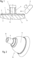
- FIG. 1 the method according to the invention is illustrated, with which a rotationally symmetrical shaped body 1 having a concentric hub 4 is produced by forming, wherein the axially extending hub 4 is closed on one side.
- a closed and, in a preferred embodiment, flat circular blank 2 is provided, indicated by dash-dotted lines. This is then inserted into a tool 5, which has an abutment chuck 9 around its circumference, on which the circular blank 2 can and then is supported with its outer edge during the subsequent process.
- a setter 6 stands on the disc 2, which has a stop shoulder 7 at a distance.
- a rotating pressure roller 8 engages the rotating round blank 2 from the outer edge with radial feed in a process step, with which the material is pressed from the outside to the inside, preferably with radial movement of the pressure roller 8, while reducing the thickness of the round blank 2 - in the area over which the pressure roller 8 travels.
- the pressure roller 8 preferably initially plunges axially into the round blank 2 close to the outer edge of the round blank 2 and is then moved radially inwards. During the first plunge, the round blank 2 preferably expands slightly and rests against the abutment chuck 9.
- the material is then pressed against the pre-setter 6 to form the hub 4.
- the thickness of the round blank 2 is reduced in some areas, resulting in a radially extending flange 3 shown in solid line in this area.
- the material used is a metal.
- the material pressed against the pre-setter 6 is guided or flows to the stop shoulder 7, so that the stop shoulder 7 forms a length limitation for the hub 4.
- a blind hole 12 with a closed bottom 13 is formed when the hub 4 is formed ( Figure 3 ).
- the blind hole 12 is formed inside the hub 4.
- the hub 4 is open at the end facing away from the flange 3 and base 13 of the blind hole 12.
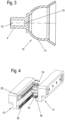
- a blank 10 with a bell-shaped lower part 11 is formed from the flange 3.
- the blank 10 also has the hub 4.
- the flange is formed or placed on this, e.g. by means of one or more pressure rollers in a pressure forming process or by means of a press in a pressing process.
- the blank 10 thus formed is in the Figures 2 and 3 Especially in the Figure 3 it can be clearly seen that the base 13 closes the blind hole 12 towards the bell-shaped lower part 11. This is particularly advantageous.
- the Figures 2 and 3 thus show an exemplary and preferred bell shape.
- the bell-shaped lower part 11 extends on one side of the base 13.
- the hub 4 extends axially on the other side of the base 13.
- the hub 4 and the bell-shaped lower part 11 are separated from each other by the base 13.
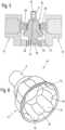
- a pivot pin is shown as a finished end product, with an inner contour, consisting in the example of six ball tracks 15 and adjacent cage tracks 16, whereby the ball tracks 15 serve to accommodate rolling balls, while the cage tracks 16 form a positive-locking holder for the rolling balls.
- embossing bars 17 which can be moved linearly in opposite directions and parallel are provided, with molding strips 20 arranged on their sides facing each other.
- these molding strips 20 are used to form the ball tracks 15 and the cage tracks 16 onto the blank 10 placed on a mold core 21 with the hub 4 and the bell-shaped lower part 11.
- the molding strips 20 each form a female mold and the mold core 21 forms a male mold with respect to the inner contour of the bell-shaped lower part 11.
- the mold core 21 is rotated with the blank 10.
- the molding strips are moved tangentially on the blank 10 so that the ball tracks 15 and the cage tracks 16 are formed.
- the blank 10 with its bell-shaped lower part 11 lies between the molding strips 20, which are pressed against the bell-shaped lower part 11 during their movement, so that the inner contour with the ball and cage tracks 15, 16 is formed.
- an internal toothing can be introduced into the hub 4, with the teeth extending in the axial direction of the hub 4.
- a corresponding shaping of the pre-setter 6 is then required, which moreover rotates together with the disk 2.
- Toothing can also be introduced into the outer surface of the hub 4, whereby both the inner and the outer toothing can also be introduced when forming the inner contour of the bell-shaped lower part 11, provided the embossing bars 17 are designed accordingly.
- the individual process steps can be carried out on a device comprising a single machine which is converted for the various successive process steps or on a device comprising several machines arranged side by side on which the individual process steps are carried out.
Landscapes
- Engineering & Computer Science (AREA)
- Mechanical Engineering (AREA)
- General Engineering & Computer Science (AREA)
- Rolling Contact Bearings (AREA)
- Forging (AREA)
- Shaping Metal By Deep-Drawing, Or The Like (AREA)
Description
- Die Erfindung betrifft ein Verfahren zur Herstellung eines rotationssymmetrischen Formkörpers nach dem Oberbegriff des Anspruchs 1.
- Derartige Formkörper finden in unterschiedlichsten Bereichen Verwendung. Exemplarisch sei hier die Herstellung eines Achs- oder Gelenkzapfens genannt, wie er beispielsweise in der
DE 10 2013 101 555 B3 offenbart ist. - Die Herstellung des daraus bekannten aus Metall, insbesondere Stahl bestehenden Formkörpers, der neben einer angeformten Nabe ein glockenförmiges, mit einer innenseitigen Konturierung versehenes Unterteil aufweist, erfolgt bevorzugt unter Einsatz eines Rohres als Halbzeug, wobei die ausgebildete Nabe in ihrem äußeren Ende durch Verformen verschlossen wird, so dass der Formkörper in seiner Endkonfiguration als einseitig offenes Bauteil vorliegt.
- Zwar wird in der genannten Literatur der Einsatz einer Ronde als Halbzeug erwähnt, jedoch sind weitere Angaben dazu nicht entnehmbar.
- Allerdings sind Einsatzfälle für einen solchen Achs- oder Gelenkzapfen vorgesehen, bei dem die Nabe beispielsweise mit einer Innenverzahnung versehen sein muss, in die ein von außen einführbares Korrespondenzteil eingreift. Dabei soll der Innenraum des Formkörpers lediglich auf der der Nabe gegenüberliegenden Seite offen sein, im Übrigen jedoch geschlossen, um ein Depot für Fett zu bilden, das zum Betrieb von Wälzkörpern dient, die in Funktion des Formteiles im Innenraum positioniert sind.
- Um einen solchen Achszapfen bereitzustellen, der also ein einseitig offenes glockenförmiges Unterteil und eine nach außen hin offene, sich an das Unterteil anschließende Nabe aufweist, erfolgt bislang die entsprechende Ausbildung der Nabe ebenso wie die des Unterteiles durch Schmieden und nachfolgendes spanendes Bearbeiten der Nabe, um eine Innenbohrung einzubringen.
- Diese Art der Fertigung ist jedoch nur mit einem hohen Aufwand zu betreiben, aus dem sich inakzeptable Fertigungskosten ergeben, die vor allem deshalb beklagenswert sind, als derartige Formteile als Serienprodukte in großen Stückzahlen Verwendung finden.
- Darüber hinaus fordert das Schmieden zu einem solchen Formteil einen hohen Materialeinsatz, der zum einen gleichfalls die Herstellungskosten nachteilig beeinflusst, und zum anderen, insbesondere bei Gelenk- oder Achszapfen, die in Kraftfahrzeugen eingesetzt werden, kontraproduktiv zu einer stets geforderten Gewichtsreduzierung, d.h., -optimierung ist.
- Ein gattungsgemäßes Verfahren ist aus der
US 2001/035036 A1 bekannt. - In der
EP 2 653 244 A1 ist ebenfalls ein Verfahren zur Herstellung eines rotationssymmetrischen Formkörpers thematisiert, der durch Umformen einer Ronde eine einseitig geschlossene, zylinderförmige Nabe aufweist. Bei einer Variante sind durch Umformen mittels Drückrollen zylindrische Formabschnitte hergestellt, wobei die angeformte Nabe auf der dem zylindrischen Formabschnitt abgewandten Seite geschlossen ist, so dass sich insgesamt eine Sackbohrung ergibt, die sich axial durch die zylindrischen Formabschnitte und die Nabe erstreckt. - Aus der
DE 101 21 546 A1 ist ein Verfahren entnehmbar, bei dem aus einer Ronde ein Getriebeteil mit einer Nabe durch Drücken mittels einer Drückrolle sowie ein die Nabe umhüllender, zylindrischer Zahnkranz geformt wird. Entgegen der Gattung weist die Nabe kein Sackloch auf, sondern eine Durchgangsbohrung. - Der Erfindung liegt die Aufgabe zugrunde, ein Verfahren der gattungsgemäßen Art so weiterzuentwickeln, dass eine fertigungs- und materialoptimierte Herstellung des rotationssymmetrischen Formkörpers möglich ist.
- Diese Aufgabe wird durch ein Verfahren mit den Merkmalen des Anspruchs 1 gelöst.
- Wie sich überraschend gezeigt hat, kann durch an sich bekanntes Drückwalzen mittels einer Drückrolle unter erfindungsgemäßem Einsatz einer geschlossenen metallischen Ronde, d. h. einer Ronde ohne ein Mittelloch, ein rotationssymmetrischer Formkörper hergestellt werden, der zu unterschiedlich konfigurierten Endprodukten weiterbearbeitet werden kann. Da kein Mittelloch vorhanden ist, wird innerhalb der Nabe vorteilhaft und einfach ein Sackloch ausgebildet, was vorteilhaft ist, wenn der Bereich innerhalb der Nabe geschlossen ausgebildet ist, beispielsweise, wenn ein Fettdepot gebildet werden soll.
- Das Ausgangsprodukt für die weitere Bearbeitung ist dabei der nach dem vorstehend beschriebenen Verfahren hergestellte rotationssymmetrische Formkörper, der in einfachster Gestaltung aus einem radial sich erstreckenden beidseitig planebenen Flansch sowie einer sich daran anschließenden, als Hohlzylinder mit geschlossenem Boden und zur dem Flansch abgewandten Seite hin offenen Nabe vorliegt.
- Eine spanende Bearbeitung zur Herstellung dieser Nabe ist somit nicht mehr erforderlich, woraus sich nicht nur die erwähnten fertigungstechnischen Vorteile ergeben, sondern auch solche hinsichtlich der Belastbarkeit. Dies insbesondere aufgrund der fehlenden Kerbwirkung durch den beim Umformen im Sinne der Erfindung ununterbrochenen Faserverlauf.
- Nach einem weiteren Gedanken der Erfindung ist vorgesehen, die Nabe mit einer Innen- und/oder Außenverzahnung zu versehen, wobei dies gleichfalls spanlos erfolgt und zwar bevorzugt während der Nabenausformung. Hierzu ist der Vorsetzer mit einer außenseitigen entsprechenden Profilierung versehen, während zur Formung einer Außenverzahnung ein außenseitig an die geformte Nabe angreifendes, gleichfalls mit einer entsprechenden Profilierung ausgestattetes Werkzeug vorgesehen ist. Im Übrigen wird der Vorsetzer mit der gleichen Umdrehung angetrieben wie die rotierende Ronde.
- Wie sich überraschend gezeigt hat, gestaltet sich die Ausbildung der Nabe besonders einfach, wenn die Ronde vor oder während der Anformung der Nabe auf eine Temperatur von etwa 400° - 1200°C erwärmt.
- In einem folgenden Arbeitsschritt kann der sich an die Nabe anschließende radiale Flansch der Ronde bzw. des gebildeten Formteils zu einem glockenförmigen Unterteil geformt werden, wobei eine beispielhafte und bevorzugte Konfiguration der eingangs genannten
DE 10 2013 101 555 B3 entnehmbar ist. Der Boden des Sacklochs liegt vorzugsweise zwischen der Nabe und dem glockenförmigen Unterteil. - Bevorzugt erfolgt diese Umformung gleichfalls nach einer Erwärmung, vorzugsweise in einem Temperaturbereich unterhalb einer Härtetemperatur.
- Die Ausformung des glockenförmigen Unterteils kann durch Pressen mittels eines geeigneten Presswerkzeuges erfolgen oder durch Drücken mit Hilfe einer rotierenden Drückrolle im Zusammenwirken mit einem Konturdorn.
- Bei einer spanlosen Bearbeitung des Formkörpers hin zu einem Achs- oder Gelenkzapfen, dessen glockenförmiges Unterteil Käfig- und Kugelbahnen aufweist, wird das als Rohling vorliegende glockenförmige Unterteil in den Bereichen partiell vorzugsweise auf erwärmt, die bei der folgenden Formgebung durch Drücken gegen den Konturdorn zu den Käfigbahnen herausgebildet werden. Dieses Erwärmen kann vorzugsweise auch auf eine Temperatur zwischen etwa 400° C und 1200° C erfolgen.
- Die Ausprägung der Käfigbahnen erfolgt gemäß einer Weiterbildung der Erfindung mittels gegenläufig linear bewegten Prägebalken, zwischen denen der Formkörper als Rohling dieses Verfahrensschrittes auf dem Konturdorn positioniert ist, wobei der Konturdorn einerseits und die Prägebalken andererseits jeweils mit einer Profilierung versehen sind, die insoweit miteinander korrespondieren, als sich die Kontur der Käfigbahn ausbildet.
- Dabei können gleichzeitig mit der Ausbildung die Käfigbahnen durch Presshärten gehärtet werden, wobei ein weiterer Vorteil dieses Verfahrensschritts darin liegt, die Käfigbahnen bereits maßlich auf ein Sollmaß zu bringen oder mit Aufmaß, wenn eine beispielsweise Hartbearbeitung nachträglich erfolgen soll.
- Auch die für den bestimmungsgemäßen Einsatz des Gelenkzapfens notwendigen Kugelbahnen werden mittels der Prägebalken ebenfalls ausgeformt und gegebenenfalls nachgehärtet.
- Weitere vorteilhafte Ausbildungen der Erfindung sind in den Unteransprüchen gekennzeichnet.
- Das erfindungsgemäße Verfahren wird nachfolgend anhand der beigefügten Zeichnungen nochmals näher erläutert.
- Es zeigen:
- Figur 1
- eine Vorrichtung zur Durchführung des Verfahrens in einer geschnittenen schematischen Seitenansicht
- Figur 2
- den in einem weiteren Verfahrensschritt zu einem Rohling geformten Formkörper in perspektivischer Ansicht
- Figur 3
- den Formkörper nach
Fig. 2 in einem Längsschnitt - Figuren 4 und 5
- eine Vorrichtung zur Weiterbearbeitung des Rohlings nach
Fig. 2 in verschiedenen Ansichten - Figur 6
- einen hinsichtlich seiner Formgebung komplettierten Formkörper in einer perspektivischen Ansicht.
- In der
Figur 1 ist das Verfahren nach der Erfindung veranschaulicht, mit dem ein rotationssymmetrischer, eine konzentrische Nabe 4 aufweisender Formkörper 1 durch Umformen hergestellt wird, wobei die sich axial erstreckende Nabe 4 einseitig geschlossen ist. - Hierzu wird eine strichpunktiert angedeutete, geschlossene und hier in bevorzugter Ausgestaltung planebene Ronde 2 bereitgestellt. Diese wird sodann in ein Werkzeug 5 eingelegt, das umfänglich ein Widerlagerfutter 9 aufweist, an dem sich die Ronde 2 mit ihrem außenseitigen Rand während des nachfolgenden Verfahrens abstützen kann und dann abstützt.
- Auf der dem Werkzeug 5 abgewandten Seite steht ein Vorsetzer 6 auf der Ronde 2 auf, der mit Abstand eine Anschlagschulter 7 aufweist.
- Die Ronde 2 wird sodann in Drehung versetzt. Zur Ausbildung der Nabe greift in einem Verfahrensschritt an die rotierende Ronde 2 vom äußeren Rand her unter radialer Zustellung eine drehbare Drückrolle 8 an, mit der unter Dickenreduzierung der Ronde 2 - in dem von der Drückrolle 8 überfahrenen Bereich - das Material vorzugsweise unter radialer Bewegung der Drückkrolle 8 von außen nach innen gedrückt wird. Die Drückrolle 8 taucht vorzugsweise zunächst nach nahe zum äußeren Rand der Ronde 2 axial in die Ronde 2 ein und wird dann/dabei radial nach innen bewegt. Beim ersten Eintauchen weitet sich die Ronde 2 vorzugsweise etwas auf und legt sich an das Widerlagerfutter 9 an.
- Das Material wird dabei sodann gegen den Vorsetzer 6 unter Ausbildung der Nabe 4 gedrückt. Dabei wird die Ronde 2 bereichsweise in ihrer Dicke reduziert, wodurch sich in diesem Bereich ein sich radial erstreckender, in Volllinie dargestellter, Flansch 3 ergibt. Das verwendete Material ist ein Metall.
- Das an den Vorsetzer 6 gedrückte Material wird bis zur Anschlagschulter 7 geführt bzw. fließt bis dort, so dass die Anschlagschulter 7 damit eine Längenbegrenzung für die Nabe 4 bildet.
- Durch die durchgehend geschlossene Ronde 2 bildet sich bei der Ausformung der Nabe 4 ein Sackloch 12 mit einem geschlossenen Boden 13 aus (
Figur 3 ). Das Sackloch 12 ist innerhalb der Nabe 4 ausgebildet. Der Boden 13, welcher die Nabe 4 axial einseitig verschließt, so dass sich das Sackloch 12 bildet, erstreckt sich radial von der Nabe radial nach innen. An dem vom Flansch 3 und Boden 13 des Sackloches 12 abgewandten Ende ist die Nabe 4 offen. - In einem folgenden Verfahrensschritt wird aus dem Flansch 3 ein Rohling 10 mit einem glockenförmigen Unterteil 11 geformt. Der Rohling 10 weist zudem die Nabe 4 auf. Dazu kann vorzugsweise ein nicht dargestellter, jedoch in der
DE 10 2013 101 555 B3 beschriebener Konturdorn verwendet werden. An diesen wird der Flansch angeformt bzw. gelegt, z.B. mittels einer oder mehreren Drückwalzen im Drückumformverfahren oder mittels einer Presse in einem Pressverfahren. - Der derart ausgebildete Rohling 10 ist in den
Figuren 2 und3 abgebildet. Vor allem in derFigur 3 ist deutlich zu erkennen, dass der Boden 13 das Sackloch 12 zum glockenförmigen Unterteil 11 hin verschließt. Dies ist besonders vorteilhaft. DieFiguren 2 und3 zeigen damit eine beispielhafte und bevorzugte Glockenform. Auf der einen Seite des Bodens 13 erstreckt sich das glockenförmige Unterteil 11. Auf der anderen Seite des Bodens 13 erstreckt sich axial die Nabe 4. Nabe 4 und glockenförmiges Unterteil 11 werden sozusagen durch en Boden 13 voneinander getrennt - In der
Figur 6 ist als ein fertiges Endprodukt ein Gelenkzapfen abgebildet, mit einer inneren Konturierung, bestehend aus im Beispiel sechs Kugelbahnen 15 und dazu benachbarten Käfigbahnen 16, wobei die Kugelbahnen 15 der Aufnahme von Wälzkugeln dienen, während die Käfigbahnen 16 eine formschlüssige Halterung der Wälzkugeln bilden. - Zur Ausbildung der Kugelbahnen 15 und der Käfigbahnen 16 an der Innenseite des glockenförmigen Unterteils 11 sind, entsprechend den Darstellungen in den
Figuren 4 und5 , gegenläufig parallel linear verfahrbare Prägebalken 17 vorgesehen, mit auf ihren einander zugewandten Seiten angeordneten Formleisten 20. Mittels dieser Formleisten 20 werden in einem weiteren Verfahrensschritt an den auf einen Formkern 21 aufgesetzten Rohling 10 mit der Nabe 4 und dem glockenförmigen Unterteil 11 die Kugelbahnen 15 und die Käfigbahnen 16 angeformt. Dabei bilden die Formleisten 20, bezogen auf die Innenkonturierung des glockenförmigen Unterteils 11, jeweils eine Matrize und der Formkern 21 eine Patrize bilden. Der Formkern 21 wird dabei mit dem Rohling 10 gedreht. Die Formleisten werden tangential an dem Rohling 10 bewegt, so dass sich die Kugelbahnen 15 und die Käfigbahnen 16 ausbilden. - Dabei liegt der Rohling 10 mit seinem glockenförmigen Unterteil 11 zwischen den Formleisten 20, die bei ihrer Bewegung gegen das glockenförmige Unterteil 11 gepresst werden, so dass sich die Innenkontur mit den Kugel- und Käfigbahnen 15, 16 herausbilden.
- Für eine synchrone Verstellung der beiden Prägebalken 17 weisen diese jeweils auf ihren einander zugewandten Seiten hier eine Zahnstange 18 auf, die mit einem Zahnrad 19 des Formkerns 21 kämmen, wobei der Rohling 10 drehfest auf dem Formkern 21 gehalten ist.
- Bereits bei der Herstellung des Formkörpers 1 kann in die Nabe 4 eine Innenverzahnung eingebracht sein, wobei die Zähne sich in Achsrichtung der Nabe 4 erstrecken. Hierzu ist dann eine entsprechende Formgebung des Vorsetzers 6 erforderlich, der im Übrigen gemeinsam mit der Ronde 2 rotiert.
- Auch in die äußere Mantelfläche der Nabe 4 kann eine Verzahnung eingebracht werden, wobei sowohl die Innen- wie auch die Außenverzahnung, bei entsprechender Ausgestaltung der Prägebalken 17, auch beim Ausformen der Innenkontur des glockenförmigen Unterteils 11 eingebracht werden kann.
- Anzumerken ist, dass die einzelnen Verfahrensschritte auf einer Vorrichtung ausgeführt werden können, die eine einzige Maschine aufweist, die für die verschiedenen aufeinander folgenden Verfahrensschritte umgerüstet wird oder auf einer Vorrichtung mit mehreren nebeneinander angeordneten Maschinen, auf denen die einzelnen Verfahrensschritte ausgeführt werden.
-
- 1
- Formkörper
- 2
- Ronde
- 3
- Flansch
- 4
- Nabe
- 5
- Werkzeug
- 6
- Vorsetzer
- 7
- Anschlagschulter
- 8
- Drückrolle
- 9
- Widerlagerfutter
- 10
- Rohling
- 11
- Unterteil
- 12
- Sackloch
- 13
- Boden
- 14
- Gelenkzapfen
- 15
- Kugelbahn
- 16
- Käfigbahn
- 17
- Prägebalken
- 18
- Zahnstange
- 19
- Zahnrad
- 20
- Formleiste
- 21
- Formkern
Claims (9)
- Verfahren zur Herstellung eines eine durch Umformen hergestellte, axial einseitig geschlossene, zylinderförmig ausgebildete konzentrische Nabe (4) aufweisenden rotationssymmetrischen Formkörpers (1), wobei an eine rotierende, geschlossene und vorzugsweise planebene Ronde (2) aus Blech mindestens eine Drückrolle (8) angreift, mit der unter Dickenreduzierung der Ronde (2) das Material radial von außen nach innen unter Ausformung der Nabe (4), mit einem Sackloch (12), gegen einen auf der Ronde (2) aufstehenden Vorsetzer (6) gedrückt wird, dadurch gekennzeichnet, dass aus einem sich radial an die Nabe (4) anschließenden Flansch (3) ein Rohling (10) in Form eines glockenförmigen Unterteils (11) durch Drücken oder Pressen gebildet wird und das Sackloch (12) einen Boden (13) aufweist, der zwischen der Nabe (4) und dem glockenförmigen Unterteil (11) liegt, wobei sich auf der einen Seite des Bodens (13) das glockenförmige Unterteil (11) und auf der anderen Seite des Bodens (13) die Nabe (4) axial erstreckt, wobei das glockenförmige Unterteil (11) mit einer Innenkontur, bestehend aus Kugelbahnen (15) zur Aufnahme von Wälzkörpern und dazu benachbarten Käfigbahnen (16) durch spanloses Anformen versehen wird und die Kugelbahnen (15) nach ihrer Ausformung gehärtet werden.
- Verfahren nach Anspruch 1, dadurch gekennzeichnet, dass die Ronde (2) vor oder während der Ausformung der Nabe erwärmt wird, vorzugsweise auf eine Temperatur von etwa 400° - 1200°C.
- Verfahren nach einem der vorstehenden Ansprüche, dadurch gekennzeichnet, dass die Nabe (4) mit einer Innen- und/oder Außenverzahnung versehen wird, wobei sich die Zähne jeweils in Achsrichtung der Nabe (4) erstrecken.
- Verfahren nach einem der vorstehenden Ansprüche, dadurch gekennzeichnet, dass die Kugelbahnen (15) und die Käfigbahnen (16) mittels parallel linear und gegenläufig bewegbaren Formleisten (20) in Korrespondenz mit einem den Rohling (10) verdrehsicher haltenden Formkern (21), unter Bildung eines Gelenkzapfens (14) ausgeformt werden.
- Verfahren nach einem der vorstehenden Ansprüche, dadurch gekennzeichnet, dass zumindest der sich an die Nabe (4) anschließende Randbereich des Flansches (3) vor oder während der Anformung des glockenförmigen Unterteils (11) erwärmt wird, vorzugsweise unter Härtetemperatur.
- Verfahren nach einem der vorstehenden Ansprüche, dadurch gekennzeichnet, dass das glockenförmige Unterteil (11) vor oder während der Ausformung der Käfigbahn (16) in deren auszubildenden Bereich auf Härtetemperatur erwärmt wird.
- Verfahren nach einem der vorstehenden Ansprüche, dadurch gekennzeichnet, dass die Formleisten (20) an den Rohling (10) angepresst werden.
- Verfahren nach einem der vorstehenden Ansprüche, dadurch gekennzeichnet, dass die Innen- und/oder Außenverzahnung beim Formen der Nabe (4) ausgeformt wird.
- Verfahren nach einem der vorstehenden Ansprüche, dadurch gekennzeichnet, dass das Sackloch (12) axial innerhalb der Nabe (4) ausgebildet wird.
Priority Applications (1)
| Application Number | Priority Date | Filing Date | Title |
|---|---|---|---|
| PL15794913T PL3221068T3 (pl) | 2014-11-17 | 2015-11-13 | Sposób wytwarzania kształtki obrotowo-symetrycznej |
Applications Claiming Priority (2)
| Application Number | Priority Date | Filing Date | Title |
|---|---|---|---|
| DE102014116786.4A DE102014116786A1 (de) | 2014-11-17 | 2014-11-17 | Verfahren zur Herstellung eines rotationssymmetrischen Formkörpers |
| PCT/EP2015/076587 WO2016079024A1 (de) | 2014-11-17 | 2015-11-13 | Verfahren zur herstellung eines rotationssymmetrischen formkörpers |
Publications (3)
| Publication Number | Publication Date |
|---|---|
| EP3221068A1 EP3221068A1 (de) | 2017-09-27 |
| EP3221068B1 EP3221068B1 (de) | 2021-04-14 |
| EP3221068B2 true EP3221068B2 (de) | 2024-06-12 |
Family
ID=54545139
Family Applications (1)
| Application Number | Title | Priority Date | Filing Date |
|---|---|---|---|
| EP15794913.2A Active EP3221068B2 (de) | 2014-11-17 | 2015-11-13 | Verfahren zur herstellung eines rotationssymmetrischen formkörpers |
Country Status (8)
| Country | Link |
|---|---|
| US (1) | US10160020B2 (de) |
| EP (1) | EP3221068B2 (de) |
| KR (1) | KR102435358B1 (de) |
| CN (1) | CN107206465B (de) |
| DE (1) | DE102014116786A1 (de) |
| ES (1) | ES2877401T3 (de) |
| PL (1) | PL3221068T3 (de) |
| WO (1) | WO2016079024A1 (de) |
Families Citing this family (3)
| Publication number | Priority date | Publication date | Assignee | Title |
|---|---|---|---|---|
| CN107096820A (zh) * | 2016-08-12 | 2017-08-29 | 鼎镁(昆山)新材料科技有限公司 | 轮圈旋压制造方法 |
| US10944669B1 (en) | 2018-02-09 | 2021-03-09 | GoTenna, Inc. | System and method for efficient network-wide broadcast in a multi-hop wireless network using packet echos |
| CN110947816A (zh) * | 2019-12-27 | 2020-04-03 | 上海交运汽车动力系统有限公司 | 一种转子支架端面旋压设备及转子支架端面旋压加工方法 |
Citations (7)
| Publication number | Priority date | Publication date | Assignee | Title |
|---|---|---|---|---|
| DE19701565A1 (de) † | 1997-01-17 | 1997-08-14 | Leico Werkzeugmaschb Gmbh & Co | Verfahren zur Herstellung eines Getriebeteils |
| EP0824049A1 (de) † | 1996-08-15 | 1998-02-18 | The Gates Corporation | Riemenscheibe mit verdickter Nabe und Verfahren zu ihrer Herstellung |
| DE19801491A1 (de) † | 1998-01-16 | 1998-07-16 | Leico Werkzeugmaschb Gmbh & Co | Verfahren und Vorrichtung zur Herstellung von Hohlkörpern durch Querwalzen |
| EP1108483A2 (de) † | 1999-12-15 | 2001-06-20 | Leico GmbH & Co. Werkzeugmaschinenbau | Verfahren und Vorrichtung zum Drückwalzen |
| EP1136150A2 (de) † | 2000-03-14 | 2001-09-26 | Nissan Motor Co., Ltd. | Verfahren zum Formen eines integralen Vorsprunges in einem Teil durch Fliessdrehen und dadurch hergestelltes Produkt |
| DE102007054754A1 (de) † | 2007-01-31 | 2008-08-07 | Wf-Maschinenbau Und Blechformtechnik Gmbh & Co Kg | Rotationssymmetrisches Getriebeteil sowie Verfahren zu dessen Herstellung |
| EP2653244A1 (de) † | 2012-04-20 | 2013-10-23 | Leifeld Metal Spinning AG | Verfahren und Vorrichtung zum Umformen eines Werkstücks |
Family Cites Families (15)
| Publication number | Priority date | Publication date | Assignee | Title |
|---|---|---|---|---|
| US4485657A (en) * | 1982-02-10 | 1984-12-04 | Ex-Cell-O Corporation | Tooth forming tool and method for splining tubular elements |
| US4694676A (en) * | 1982-07-28 | 1987-09-22 | General Motors Corporation | Method of manufacturing tri-pot universal joint housings |
| DE4425033C2 (de) | 1994-07-15 | 1999-07-29 | Fraunhofer Ges Forschung | Verfahren und Vorrichtung zum Drückumformen von Werkstücken |
| JPH10244344A (ja) | 1997-02-28 | 1998-09-14 | Unisia Jecs Corp | カップ状ソケット部材の成形装置 |
| DE19820472A1 (de) * | 1997-03-20 | 1998-10-15 | Leico Werkzeugmaschb Gmbh & Co | Verfahren zur Herstellung von profilierten Hohlkörpern |
| JP3860889B2 (ja) * | 1997-09-17 | 2006-12-20 | 本田技研工業株式会社 | しごき加工方法およびその装置 |
| DE29906427U1 (de) | 1999-02-16 | 1999-06-02 | Wf-Maschinenbau Und Blechformtechnik Gmbh & Co Kg, 48324 Sendenhorst | Vorrichtung zur Herstellung einer Nabe |
| DE19958343A1 (de) | 1999-12-03 | 2001-06-21 | Peter Groche | Verfahren zur Herstellung einer hohlen Welle mit Außenverzahnungen und Lagersitzen |
| US6427329B2 (en) | 2000-04-26 | 2002-08-06 | A. J. Rose Manufacturing Co. | Method of forming a hub with blind bore |
| DE10033244A1 (de) * | 2000-07-10 | 2002-01-24 | Wf Maschinenbau Blechformtech | Verfahren zur Herstellung eines eine Nabe aufweisenden Getriebeteiles |
| DE10121546B4 (de) | 2001-05-03 | 2006-05-24 | Leifeld Metal Spinning Gmbh | Verfahren und Drückrolle zum Anformen einer Nabe |
| DE102007022012A1 (de) | 2007-05-08 | 2008-11-13 | Andreas Thomas | Drückmaschine zur Verarbeitung von blechförmigen Materialien mit verschwenkbar gelagertem Drückwerkzeug |
| DE102007023972A1 (de) | 2007-05-23 | 2008-11-27 | Wf-Maschinenbau Und Blechformtechnik Gmbh & Co Kg | Verfahren zur Herstellung einer Nabe im Drückverfahren mittels wenigstens einer drehbaren Drückrolle |
| JP5359877B2 (ja) * | 2007-10-02 | 2013-12-04 | 日本精工株式会社 | 転がり軸受ユニット用軌道輪部材の製造方法 |
| DE102013101555B3 (de) | 2013-02-15 | 2014-05-22 | Thyssenkrupp Steel Europe Ag | Verfahren und Vorrichtung zur Herstellung eines Achszapfens |
-
2014
- 2014-11-17 DE DE102014116786.4A patent/DE102014116786A1/de not_active Ceased
-
2015
- 2015-11-13 PL PL15794913T patent/PL3221068T3/pl unknown
- 2015-11-13 CN CN201580061468.4A patent/CN107206465B/zh not_active Expired - Fee Related
- 2015-11-13 ES ES15794913T patent/ES2877401T3/es active Active
- 2015-11-13 KR KR1020177016539A patent/KR102435358B1/ko active Active
- 2015-11-13 WO PCT/EP2015/076587 patent/WO2016079024A1/de not_active Ceased
- 2015-11-13 EP EP15794913.2A patent/EP3221068B2/de active Active
- 2015-11-13 US US15/527,075 patent/US10160020B2/en active Active
Patent Citations (8)
| Publication number | Priority date | Publication date | Assignee | Title |
|---|---|---|---|---|
| EP0824049A1 (de) † | 1996-08-15 | 1998-02-18 | The Gates Corporation | Riemenscheibe mit verdickter Nabe und Verfahren zu ihrer Herstellung |
| DE19701565A1 (de) † | 1997-01-17 | 1997-08-14 | Leico Werkzeugmaschb Gmbh & Co | Verfahren zur Herstellung eines Getriebeteils |
| DE19801491A1 (de) † | 1998-01-16 | 1998-07-16 | Leico Werkzeugmaschb Gmbh & Co | Verfahren und Vorrichtung zur Herstellung von Hohlkörpern durch Querwalzen |
| EP1108483A2 (de) † | 1999-12-15 | 2001-06-20 | Leico GmbH & Co. Werkzeugmaschinenbau | Verfahren und Vorrichtung zum Drückwalzen |
| EP1136150A2 (de) † | 2000-03-14 | 2001-09-26 | Nissan Motor Co., Ltd. | Verfahren zum Formen eines integralen Vorsprunges in einem Teil durch Fliessdrehen und dadurch hergestelltes Produkt |
| US20010039864A1 (en) † | 2000-03-14 | 2001-11-15 | Nissan Motor Co., Ltd | Method of forming an integral tubluar projection in a work by spinning and a product produced by the same |
| DE102007054754A1 (de) † | 2007-01-31 | 2008-08-07 | Wf-Maschinenbau Und Blechformtechnik Gmbh & Co Kg | Rotationssymmetrisches Getriebeteil sowie Verfahren zu dessen Herstellung |
| EP2653244A1 (de) † | 2012-04-20 | 2013-10-23 | Leifeld Metal Spinning AG | Verfahren und Vorrichtung zum Umformen eines Werkstücks |
Also Published As
| Publication number | Publication date |
|---|---|
| DE102014116786A1 (de) | 2016-05-19 |
| ES2877401T3 (es) | 2021-11-16 |
| CN107206465B (zh) | 2020-06-26 |
| KR20170092584A (ko) | 2017-08-11 |
| US20170333973A1 (en) | 2017-11-23 |
| CN107206465A (zh) | 2017-09-26 |
| WO2016079024A1 (de) | 2016-05-26 |
| KR102435358B1 (ko) | 2022-08-22 |
| EP3221068B1 (de) | 2021-04-14 |
| EP3221068A1 (de) | 2017-09-27 |
| PL3221068T3 (pl) | 2021-10-25 |
| US10160020B2 (en) | 2018-12-25 |
Similar Documents
| Publication | Publication Date | Title |
|---|---|---|
| EP2127775B1 (de) | Verfahren zur Fertigung von Werkstücken und Drückwalzmaschine dazu | |
| EP1108483B1 (de) | Verfahren und Vorrichtung zum Drückwalzen | |
| DE102014017407A1 (de) | Verfahren zur Herstellung einer profilierten Hohlwelle für eine teleskopierbare Lenkwelle und teleskopierbare Lenkwelle | |
| EP2641673B1 (de) | Verfahren und Vorrichtung zur Herstellung eines Verbindungsabschnitts als Teil eines Werkzeugs | |
| DE102012005106A1 (de) | Verfahren zur Herstellung einer Hohlwelle und Vorrichtung hierfür | |
| EP2484462A2 (de) | Verwendung eines Warmstauchverfahrens, Verwendung eines Umformwerkzeugs, Verfahren zum Erzeugen einer Schmiedevorform und Umformvorrichtung oder Warmstauchvorrichtung | |
| AT17771U1 (de) | Werkzeug und verfahren zur herstellung eines schrägverzahnten sektorzahnrads und zugehöriges schrägsektorzahnrad | |
| EP3436208B1 (de) | Verfahren zur herstellung eines eine nabe aufweisenden formkörpers sowie vorrichtung zur durchführung des verfahrens | |
| EP0955110B1 (de) | Verfahren zum Drückwalzen und Drückwalzvorrichtung | |
| EP3221068B2 (de) | Verfahren zur herstellung eines rotationssymmetrischen formkörpers | |
| EP2723516B1 (de) | Schmiedeverfahren zur herstellung eines kolbens bzw. kolbenschafts | |
| EP1356891A1 (de) | Verfahren zur Herstellung von Schiebemuffen für Schaltgetriebe | |
| EP3010667B1 (de) | Verfahren und vorrichtung zur herstellung rotationssymmetrischer metallbauteile | |
| EP2561938B1 (de) | Verfahren zum Herstellen eines Synchronrings | |
| DE2808198A1 (de) | Verfahren und vorrichtung zur bildung eines achsschenkels an einem hohlen achsrohling | |
| DE102008023696A1 (de) | Verfahren zur Herstellung von Hohlwellengrundkörpern sowie nach dem Verfahren hergestellte Hohlwellengrundkörper | |
| EP3023171B1 (de) | Drückwalzen von lagerringen | |
| EP0997210B1 (de) | Verfahren zum Formen eines scheibenförmigen Teiles mit Nabe und Umformrolle für das Verfahren | |
| DE102008038127B3 (de) | Verfahren und Vorrichtung zur Herstellung von hochgenauen innen- und außenverzahnten, topfförmigen Blechteilen | |
| DE4321779B4 (de) | Verfahren zur Herstellung eines Starterkranz-Zahnrads aus Blech und nach dem Verfahren hergestelltes Starterkranz-Zahnrad | |
| EP2771137B1 (de) | Kombination einer vorrichtung und einer vorform und verfahren zum herstellen eines leicht-metallrades | |
| EP1136225A2 (de) | Spritzgiesswerkzeug und Verfahren zum Herstellen eines inneren Formteils desselben | |
| DE102009059265A1 (de) | Verfahren und Vorrichtung zur Herstellung einer Innenverzahnung eines Getriebeteiles | |
| DE102016115791A1 (de) | Verfahren zur spanlosen Herstellung eines rotationssymmetrischen Körpers aus einer Blechronde | |
| EP0893177B1 (de) | Verfahren zur Herstellung eines stirnverzahnten Werkstückes |
Legal Events
| Date | Code | Title | Description |
|---|---|---|---|
| STAA | Information on the status of an ep patent application or granted ep patent |
Free format text: STATUS: THE INTERNATIONAL PUBLICATION HAS BEEN MADE |
|
| PUAI | Public reference made under article 153(3) epc to a published international application that has entered the european phase |
Free format text: ORIGINAL CODE: 0009012 |
|
| STAA | Information on the status of an ep patent application or granted ep patent |
Free format text: STATUS: REQUEST FOR EXAMINATION WAS MADE |
|
| 17P | Request for examination filed |
Effective date: 20170601 |
|
| AK | Designated contracting states |
Kind code of ref document: A1 Designated state(s): AL AT BE BG CH CY CZ DE DK EE ES FI FR GB GR HR HU IE IS IT LI LT LU LV MC MK MT NL NO PL PT RO RS SE SI SK SM TR |
|
| AX | Request for extension of the european patent |
Extension state: BA ME |
|
| RIN1 | Information on inventor provided before grant (corrected) |
Inventor name: GOEVERT, MICHAEL Inventor name: OHLSCHER, HEIKO |
|
| DAV | Request for validation of the european patent (deleted) | ||
| DAX | Request for extension of the european patent (deleted) | ||
| TPAC | Observations filed by third parties |
Free format text: ORIGINAL CODE: EPIDOSNTIPA |
|
| STAA | Information on the status of an ep patent application or granted ep patent |
Free format text: STATUS: EXAMINATION IS IN PROGRESS |
|
| 17Q | First examination report despatched |
Effective date: 20190304 |
|
| TPAC | Observations filed by third parties |
Free format text: ORIGINAL CODE: EPIDOSNTIPA |
|
| TPAC | Observations filed by third parties |
Free format text: ORIGINAL CODE: EPIDOSNTIPA |
|
| GRAP | Despatch of communication of intention to grant a patent |
Free format text: ORIGINAL CODE: EPIDOSNIGR1 |
|
| STAA | Information on the status of an ep patent application or granted ep patent |
Free format text: STATUS: GRANT OF PATENT IS INTENDED |
|
| INTG | Intention to grant announced |
Effective date: 20201123 |
|
| GRAS | Grant fee paid |
Free format text: ORIGINAL CODE: EPIDOSNIGR3 |
|
| GRAA | (expected) grant |
Free format text: ORIGINAL CODE: 0009210 |
|
| STAA | Information on the status of an ep patent application or granted ep patent |
Free format text: STATUS: THE PATENT HAS BEEN GRANTED |
|
| AK | Designated contracting states |
Kind code of ref document: B1 Designated state(s): AL AT BE BG CH CY CZ DE DK EE ES FI FR GB GR HR HU IE IS IT LI LT LU LV MC MK MT NL NO PL PT RO RS SE SI SK SM TR |
|
| REG | Reference to a national code |
Ref country code: GB Ref legal event code: FG4D Free format text: NOT ENGLISH |
|
| REG | Reference to a national code |
Ref country code: CH Ref legal event code: EP |
|
| REG | Reference to a national code |
Ref country code: DE Ref legal event code: R096 Ref document number: 502015014571 Country of ref document: DE |
|
| REG | Reference to a national code |
Ref country code: IE Ref legal event code: FG4D Free format text: LANGUAGE OF EP DOCUMENT: GERMAN |
|
| REG | Reference to a national code |
Ref country code: AT Ref legal event code: REF Ref document number: 1381859 Country of ref document: AT Kind code of ref document: T Effective date: 20210515 |
|
| REG | Reference to a national code |
Ref country code: LT Ref legal event code: MG9D |
|
| REG | Reference to a national code |
Ref country code: SK Ref legal event code: T3 Ref document number: E 37401 Country of ref document: SK |
|
| REG | Reference to a national code |
Ref country code: NL Ref legal event code: MP Effective date: 20210414 |
|
| PG25 | Lapsed in a contracting state [announced via postgrant information from national office to epo] |
Ref country code: LT Free format text: LAPSE BECAUSE OF FAILURE TO SUBMIT A TRANSLATION OF THE DESCRIPTION OR TO PAY THE FEE WITHIN THE PRESCRIBED TIME-LIMIT Effective date: 20210414 Ref country code: NL Free format text: LAPSE BECAUSE OF FAILURE TO SUBMIT A TRANSLATION OF THE DESCRIPTION OR TO PAY THE FEE WITHIN THE PRESCRIBED TIME-LIMIT Effective date: 20210414 Ref country code: FI Free format text: LAPSE BECAUSE OF FAILURE TO SUBMIT A TRANSLATION OF THE DESCRIPTION OR TO PAY THE FEE WITHIN THE PRESCRIBED TIME-LIMIT Effective date: 20210414 Ref country code: BG Free format text: LAPSE BECAUSE OF FAILURE TO SUBMIT A TRANSLATION OF THE DESCRIPTION OR TO PAY THE FEE WITHIN THE PRESCRIBED TIME-LIMIT Effective date: 20210714 Ref country code: HR Free format text: LAPSE BECAUSE OF FAILURE TO SUBMIT A TRANSLATION OF THE DESCRIPTION OR TO PAY THE FEE WITHIN THE PRESCRIBED TIME-LIMIT Effective date: 20210414 |
|
| REG | Reference to a national code |
Ref country code: ES Ref legal event code: FG2A Ref document number: 2877401 Country of ref document: ES Kind code of ref document: T3 Effective date: 20211116 |
|
| PG25 | Lapsed in a contracting state [announced via postgrant information from national office to epo] |
Ref country code: RS Free format text: LAPSE BECAUSE OF FAILURE TO SUBMIT A TRANSLATION OF THE DESCRIPTION OR TO PAY THE FEE WITHIN THE PRESCRIBED TIME-LIMIT Effective date: 20210414 Ref country code: SE Free format text: LAPSE BECAUSE OF FAILURE TO SUBMIT A TRANSLATION OF THE DESCRIPTION OR TO PAY THE FEE WITHIN THE PRESCRIBED TIME-LIMIT Effective date: 20210414 Ref country code: PT Free format text: LAPSE BECAUSE OF FAILURE TO SUBMIT A TRANSLATION OF THE DESCRIPTION OR TO PAY THE FEE WITHIN THE PRESCRIBED TIME-LIMIT Effective date: 20210816 Ref country code: NO Free format text: LAPSE BECAUSE OF FAILURE TO SUBMIT A TRANSLATION OF THE DESCRIPTION OR TO PAY THE FEE WITHIN THE PRESCRIBED TIME-LIMIT Effective date: 20210714 Ref country code: LV Free format text: LAPSE BECAUSE OF FAILURE TO SUBMIT A TRANSLATION OF THE DESCRIPTION OR TO PAY THE FEE WITHIN THE PRESCRIBED TIME-LIMIT Effective date: 20210414 Ref country code: GR Free format text: LAPSE BECAUSE OF FAILURE TO SUBMIT A TRANSLATION OF THE DESCRIPTION OR TO PAY THE FEE WITHIN THE PRESCRIBED TIME-LIMIT Effective date: 20210715 Ref country code: IS Free format text: LAPSE BECAUSE OF FAILURE TO SUBMIT A TRANSLATION OF THE DESCRIPTION OR TO PAY THE FEE WITHIN THE PRESCRIBED TIME-LIMIT Effective date: 20210814 |
|
| REG | Reference to a national code |
Ref country code: DE Ref legal event code: R026 Ref document number: 502015014571 Country of ref document: DE |
|
| PLBI | Opposition filed |
Free format text: ORIGINAL CODE: 0009260 |
|
| PLAX | Notice of opposition and request to file observation + time limit sent |
Free format text: ORIGINAL CODE: EPIDOSNOBS2 |
|
| PG25 | Lapsed in a contracting state [announced via postgrant information from national office to epo] |
Ref country code: SM Free format text: LAPSE BECAUSE OF FAILURE TO SUBMIT A TRANSLATION OF THE DESCRIPTION OR TO PAY THE FEE WITHIN THE PRESCRIBED TIME-LIMIT Effective date: 20210414 Ref country code: EE Free format text: LAPSE BECAUSE OF FAILURE TO SUBMIT A TRANSLATION OF THE DESCRIPTION OR TO PAY THE FEE WITHIN THE PRESCRIBED TIME-LIMIT Effective date: 20210414 Ref country code: DK Free format text: LAPSE BECAUSE OF FAILURE TO SUBMIT A TRANSLATION OF THE DESCRIPTION OR TO PAY THE FEE WITHIN THE PRESCRIBED TIME-LIMIT Effective date: 20210414 Ref country code: RO Free format text: LAPSE BECAUSE OF FAILURE TO SUBMIT A TRANSLATION OF THE DESCRIPTION OR TO PAY THE FEE WITHIN THE PRESCRIBED TIME-LIMIT Effective date: 20210414 |
|
| 26 | Opposition filed |
Opponent name: LEIFELD METAL SPINNING GMBH Effective date: 20220112 |
|
| PLAF | Information modified related to communication of a notice of opposition and request to file observations + time limit |
Free format text: ORIGINAL CODE: EPIDOSCOBS2 |
|
| PLAS | Information related to reply of patent proprietor to notice(s) of opposition deleted |
Free format text: ORIGINAL CODE: EPIDOSDOBS3 |
|
| PLBB | Reply of patent proprietor to notice(s) of opposition received |
Free format text: ORIGINAL CODE: EPIDOSNOBS3 |
|
| PG25 | Lapsed in a contracting state [announced via postgrant information from national office to epo] |
Ref country code: IS Free format text: LAPSE BECAUSE OF FAILURE TO SUBMIT A TRANSLATION OF THE DESCRIPTION OR TO PAY THE FEE WITHIN THE PRESCRIBED TIME-LIMIT Effective date: 20210814 Ref country code: AL Free format text: LAPSE BECAUSE OF FAILURE TO SUBMIT A TRANSLATION OF THE DESCRIPTION OR TO PAY THE FEE WITHIN THE PRESCRIBED TIME-LIMIT Effective date: 20210414 |
|
| PG25 | Lapsed in a contracting state [announced via postgrant information from national office to epo] |
Ref country code: MC Free format text: LAPSE BECAUSE OF FAILURE TO SUBMIT A TRANSLATION OF THE DESCRIPTION OR TO PAY THE FEE WITHIN THE PRESCRIBED TIME-LIMIT Effective date: 20210414 |
|
| REG | Reference to a national code |
Ref country code: CH Ref legal event code: PL |
|
| GBPC | Gb: european patent ceased through non-payment of renewal fee |
Effective date: 20211113 |
|
| PLBB | Reply of patent proprietor to notice(s) of opposition received |
Free format text: ORIGINAL CODE: EPIDOSNOBS3 |
|
| PG25 | Lapsed in a contracting state [announced via postgrant information from national office to epo] |
Ref country code: LU Free format text: LAPSE BECAUSE OF NON-PAYMENT OF DUE FEES Effective date: 20211113 Ref country code: BE Free format text: LAPSE BECAUSE OF NON-PAYMENT OF DUE FEES Effective date: 20211130 |
|
| REG | Reference to a national code |
Ref country code: BE Ref legal event code: MM Effective date: 20211130 |
|
| PG25 | Lapsed in a contracting state [announced via postgrant information from national office to epo] |
Ref country code: IE Free format text: LAPSE BECAUSE OF NON-PAYMENT OF DUE FEES Effective date: 20211113 Ref country code: GB Free format text: LAPSE BECAUSE OF NON-PAYMENT OF DUE FEES Effective date: 20211113 |
|
| PGFP | Annual fee paid to national office [announced via postgrant information from national office to epo] |
Ref country code: SK Payment date: 20220908 Year of fee payment: 8 Ref country code: CZ Payment date: 20220908 Year of fee payment: 8 |
|
| PGFP | Annual fee paid to national office [announced via postgrant information from national office to epo] |
Ref country code: PL Payment date: 20220822 Year of fee payment: 8 |
|
| REG | Reference to a national code |
Ref country code: AT Ref legal event code: MM01 Ref document number: 1381859 Country of ref document: AT Kind code of ref document: T Effective date: 20211113 |
|
| PG25 | Lapsed in a contracting state [announced via postgrant information from national office to epo] |
Ref country code: AT Free format text: LAPSE BECAUSE OF NON-PAYMENT OF DUE FEES Effective date: 20211113 |
|
| PGFP | Annual fee paid to national office [announced via postgrant information from national office to epo] |
Ref country code: IT Payment date: 20221130 Year of fee payment: 8 Ref country code: FR Payment date: 20221110 Year of fee payment: 8 Ref country code: ES Payment date: 20221202 Year of fee payment: 8 |
|
| PG25 | Lapsed in a contracting state [announced via postgrant information from national office to epo] |
Ref country code: HU Free format text: LAPSE BECAUSE OF FAILURE TO SUBMIT A TRANSLATION OF THE DESCRIPTION OR TO PAY THE FEE WITHIN THE PRESCRIBED TIME-LIMIT; INVALID AB INITIO Effective date: 20151113 |
|
| PG25 | Lapsed in a contracting state [announced via postgrant information from national office to epo] |
Ref country code: CY Free format text: LAPSE BECAUSE OF FAILURE TO SUBMIT A TRANSLATION OF THE DESCRIPTION OR TO PAY THE FEE WITHIN THE PRESCRIBED TIME-LIMIT Effective date: 20210414 |
|
| PG25 | Lapsed in a contracting state [announced via postgrant information from national office to epo] |
Ref country code: LI Free format text: LAPSE BECAUSE OF NON-PAYMENT OF DUE FEES Effective date: 20220630 Ref country code: CH Free format text: LAPSE BECAUSE OF NON-PAYMENT OF DUE FEES Effective date: 20220630 |
|
| PG25 | Lapsed in a contracting state [announced via postgrant information from national office to epo] |
Ref country code: MK Free format text: LAPSE BECAUSE OF FAILURE TO SUBMIT A TRANSLATION OF THE DESCRIPTION OR TO PAY THE FEE WITHIN THE PRESCRIBED TIME-LIMIT Effective date: 20210414 |
|
| PUAH | Patent maintained in amended form |
Free format text: ORIGINAL CODE: 0009272 |
|
| STAA | Information on the status of an ep patent application or granted ep patent |
Free format text: STATUS: PATENT MAINTAINED AS AMENDED |
|
| 27A | Patent maintained in amended form |
Effective date: 20240612 |
|
| AK | Designated contracting states |
Kind code of ref document: B2 Designated state(s): AL AT BE BG CH CY CZ DE DK EE ES FI FR GB GR HR HU IE IS IT LI LT LU LV MC MK MT NL NO PL PT RO RS SE SI SK SM TR |
|
| REG | Reference to a national code |
Ref country code: DE Ref legal event code: R102 Ref document number: 502015014571 Country of ref document: DE |
|
| PG25 | Lapsed in a contracting state [announced via postgrant information from national office to epo] |
Ref country code: CZ Free format text: LAPSE BECAUSE OF NON-PAYMENT OF DUE FEES Effective date: 20231113 |
|
| PG25 | Lapsed in a contracting state [announced via postgrant information from national office to epo] |
Ref country code: SK Free format text: LAPSE BECAUSE OF NON-PAYMENT OF DUE FEES Effective date: 20231113 |
|
| PG25 | Lapsed in a contracting state [announced via postgrant information from national office to epo] |
Ref country code: SK Free format text: LAPSE BECAUSE OF NON-PAYMENT OF DUE FEES Effective date: 20231113 Ref country code: CZ Free format text: LAPSE BECAUSE OF NON-PAYMENT OF DUE FEES Effective date: 20231113 |
|
| PG25 | Lapsed in a contracting state [announced via postgrant information from national office to epo] |
Ref country code: MT Free format text: LAPSE BECAUSE OF FAILURE TO SUBMIT A TRANSLATION OF THE DESCRIPTION OR TO PAY THE FEE WITHIN THE PRESCRIBED TIME-LIMIT Effective date: 20210414 |
|
| PG25 | Lapsed in a contracting state [announced via postgrant information from national office to epo] |
Ref country code: FR Free format text: LAPSE BECAUSE OF NON-PAYMENT OF DUE FEES Effective date: 20231130 |
|
| PG25 | Lapsed in a contracting state [announced via postgrant information from national office to epo] |
Ref country code: ES Free format text: LAPSE BECAUSE OF FAILURE TO SUBMIT A TRANSLATION OF THE DESCRIPTION OR TO PAY THE FEE WITHIN THE PRESCRIBED TIME-LIMIT Effective date: 20240612 |
|
| PG25 | Lapsed in a contracting state [announced via postgrant information from national office to epo] |
Ref country code: FR Free format text: LAPSE BECAUSE OF NON-PAYMENT OF DUE FEES Effective date: 20231130 Ref country code: ES Free format text: LAPSE BECAUSE OF FAILURE TO SUBMIT A TRANSLATION OF THE DESCRIPTION OR TO PAY THE FEE WITHIN THE PRESCRIBED TIME-LIMIT Effective date: 20240612 |
|
| PG25 | Lapsed in a contracting state [announced via postgrant information from national office to epo] |
Ref country code: IT Free format text: LAPSE BECAUSE OF NON-PAYMENT OF DUE FEES Effective date: 20231113 |
|
| PG25 | Lapsed in a contracting state [announced via postgrant information from national office to epo] |
Ref country code: IT Free format text: LAPSE BECAUSE OF NON-PAYMENT OF DUE FEES Effective date: 20231113 |
|
| PGFP | Annual fee paid to national office [announced via postgrant information from national office to epo] |
Ref country code: DE Payment date: 20251010 Year of fee payment: 11 |
|
| PG25 | Lapsed in a contracting state [announced via postgrant information from national office to epo] |
Ref country code: PL Free format text: LAPSE BECAUSE OF NON-PAYMENT OF DUE FEES Effective date: 20231113 |