EP3217412B1 - Interrupteur pour une machine-outil portative - Google Patents
Interrupteur pour une machine-outil portative Download PDFInfo
- Publication number
- EP3217412B1 EP3217412B1 EP17158010.3A EP17158010A EP3217412B1 EP 3217412 B1 EP3217412 B1 EP 3217412B1 EP 17158010 A EP17158010 A EP 17158010A EP 3217412 B1 EP3217412 B1 EP 3217412B1
- Authority
- EP
- European Patent Office
- Prior art keywords
- actuator
- locking element
- switch
- locking
- actuating
- Prior art date
- Legal status (The legal status is an assumption and is not a legal conclusion. Google has not performed a legal analysis and makes no representation as to the accuracy of the status listed.)
- Active
Links
- 210000003811 finger Anatomy 0.000 description 5
- 238000003754 machining Methods 0.000 description 3
- 238000003801 milling Methods 0.000 description 2
- 239000004033 plastic Substances 0.000 description 2
- 230000007704 transition Effects 0.000 description 2
- 238000004146 energy storage Methods 0.000 description 1
- 230000029142 excretion Effects 0.000 description 1
- 230000002349 favourable effect Effects 0.000 description 1
- 210000005224 forefinger Anatomy 0.000 description 1
- 230000003287 optical effect Effects 0.000 description 1
- 230000001681 protective effect Effects 0.000 description 1
- 210000003813 thumb Anatomy 0.000 description 1
Images

Classifications
-
- H—ELECTRICITY
- H01—ELECTRIC ELEMENTS
- H01H—ELECTRIC SWITCHES; RELAYS; SELECTORS; EMERGENCY PROTECTIVE DEVICES
- H01H9/00—Details of switching devices, not covered by groups H01H1/00 - H01H7/00
- H01H9/02—Bases, casings, or covers
- H01H9/06—Casing of switch constituted by a handle serving a purpose other than the actuation of the switch, e.g. by the handle of a vacuum cleaner
-
- H—ELECTRICITY
- H01—ELECTRIC ELEMENTS
- H01H—ELECTRIC SWITCHES; RELAYS; SELECTORS; EMERGENCY PROTECTIVE DEVICES
- H01H13/00—Switches having rectilinearly-movable operating part or parts adapted for pushing or pulling in one direction only, e.g. push-button switch
- H01H13/02—Details
- H01H13/04—Cases; Covers
- H01H13/08—Casing of switch constituted by a handle serving a purpose other than the actuation of the switch
-
- H—ELECTRICITY
- H01—ELECTRIC ELEMENTS
- H01H—ELECTRIC SWITCHES; RELAYS; SELECTORS; EMERGENCY PROTECTIVE DEVICES
- H01H3/00—Mechanisms for operating contacts
- H01H3/02—Operating parts, i.e. for operating driving mechanism by a mechanical force external to the switch
- H01H3/20—Operating parts, i.e. for operating driving mechanism by a mechanical force external to the switch wherein an auxiliary movement thereof, or of an attachment thereto, is necessary before the main movement is possible or effective, e.g. for unlatching, for coupling
-
- H—ELECTRICITY
- H01—ELECTRIC ELEMENTS
- H01H—ELECTRIC SWITCHES; RELAYS; SELECTORS; EMERGENCY PROTECTIVE DEVICES
- H01H21/00—Switches operated by an operating part in the form of a pivotable member acted upon directly by a solid body, e.g. by a hand
- H01H21/02—Details
- H01H21/18—Movable parts; Contacts mounted thereon
- H01H21/36—Driving mechanisms
- H01H21/50—Driving mechanisms with indexing or latching means, e.g. indexing by ball and spring; with means to ensure stopping at intermediate operative positions
-
- H—ELECTRICITY
- H01—ELECTRIC ELEMENTS
- H01H—ELECTRIC SWITCHES; RELAYS; SELECTORS; EMERGENCY PROTECTIVE DEVICES
- H01H9/00—Details of switching devices, not covered by groups H01H1/00 - H01H7/00
- H01H9/20—Interlocking, locking, or latching mechanisms
- H01H9/22—Interlocking, locking, or latching mechanisms for interlocking between casing, cover, or protective shutter and mechanism for operating contacts
Definitions
- the invention relates to a switch for an electrical device in the form of a hand-held machine tool, a mobile table-top machine tool or a vacuum cleaner or as part of such an electrical device, according to the preamble of claim 1.
- Such a switch is for example in EP 2 884 515 A1 described.
- Such switches are configured, for example, as a slide switch or pressure switch, with which electrical contacts can be closed or opened to turn on or off the electrical device.
- the switch is loaded in the open position by a spring, especially in safety-related devices.
- the device such as a sawing machine, turns off when the operator releases the switch.
- it is allowed to block the switch in the closed position by means of a slider,
- the switch allows ergonomic operation, namely because the locking element is mounted on the actuator.
- the locking element is thus movable together with the actuator so that it is available for locking the actuator, so to speak in place, namely the desired position of the actuator available.
- the actuator In the active position, the actuator actuates the contact arrangement expediently in the closed position.
- the contact arrangement When the actuator is in the active position, the contact arrangement is advantageously held in the closed position. For example, actuates the actuator in its active position, an actuating element of the contact arrangement in the closed position.
- the actuator In the inactive position, the actuator allows, for example, an adjustment of the contact arrangement in the open position, in particular by a spring, the contact arrangement, in particular an actuating element of the contact arrangement, adjusted to the off position. It is also possible that the actuator in the inactive position or during the adjustment in the inactive position actively actuates or takes away the contact arrangement in the off position.
- the locking element forms an actuating element for adjusting the actuator between the active position and the inactive position and has the actuating surface.
- the actuator can be operated on the basis of the locking element between the active position and the inactive position.
- the locking element forms the exclusive or sole actuating element, with which the actuator between the active position and the inactive position is adjustable, in particular from the inactive position in the direction of the active position or the closed position of the switch.
- the actuating arrangement and / or the actuating surface are preferably provided exclusively on the locking element.
- the actuator has no actuating area or no actuating area.
- the actuator expediently has no by an operator operable actuating surface. It is particularly advantageous if the actuator has no actuating surface or actuating contour that can be directly actuated or gripped by the operator.
- the actuator and ultimately the contact assembly is operated by the locking element in a function as an actuator or is operable by the locking element.
- the locking element expediently forms the sole and / or exclusive actuating element for actuating the switch and / or the single component of the switch, which has the or an actuating surface.
- the actuator is adjustable solely by means of the locking element, which forms an actuating element, by the operator between the inactive position and the active position, in particular in the direction of the active position.
- the actuator bearing and / or the locking element bearing comprises a sliding bearing, a pivot bearing or a combination thereof. It is particularly preferred if one or both of the bearings is designed as a pivot bearing or are.
- a respective bearing, the actuator bearing and / or the locking element bearing is preferably a bearing with at least one bearing axis element, which is received in a bearing receptacle pivotally and / or displaceably.
- one or both bearings it is also possible for one or both bearings to have a flexible connecting section between, for example, the switch base and the actuator (in the case of the actuator bearing) or the actuator and the locking element (in the case of the locking element bearing).
- at least one of the bearings may be a flexurally flexible connection between the bearings formed by the bearing relative to each other movable components.
- the actuator is advantageous with respect to the switch base about a first pivot axis and the latch member with respect to the actuator about a second pivot axis pivoted.
- these two adjusting axes can run parallel to one another.
- the adjusting axes include an angle, in particular a shallow angle of about 1 ° to 40 ° or 5-20 °.
- the locking element is thus preferably mounted in the manner of a tiltable or pivotable component on the actuator, so that it is movable between a locking position and an unlocked position.
- the actuator expediently comprises a pivoting arm projecting from the actuator bearing or is formed thereby, on which the locking element is movably mounted on the basis of the locking element bearing.
- the locking element has, for example, a T-shaped side view.
- the actuator and the locking element as a whole form a T-shaped configuration.
- the actuator forms or comprises the base leg of this configuration, on which the locking element forms or has the transverse section.
- the locking element may form a portion of the base leg. It is advantageous if the locking element bearing is arranged at this base leg or at the transition region between the base leg and the locking element.
- Ergonomically favorable is the following actuation concept:
- An unlocking operation direction or an unlocking operation path, in particular an unlocking operation axis, for adjusting the locking element from a locking position locking the actuator in an opening provided for adjusting the actuator unlocking position and a switching operation direction or a switching operation path, in particular a switching operation axis , for adjusting the actuator between the off position and the closed position are advantageous to each other at an angle, in particular approximately at right angles.
- the respective actuating direction can be oriented along an actuating axis or even a curved actuating path.
- the actuating track can be rectilinear thus represent an actuating axis.
- unlocking-actuating direction or unlocking-actuating track approximately radially with respect to a pivot axis of the locking element bearing or parallel to an emanating from the locking element bearing radius line runs. In a switching operation of the locking element this pivots, for example, about a pivot axis of the actuator bearing and thus takes the actuator with in the direction of the active position.
- switching actuating direction or switching actuating path or switching actuating axis runs tangentially or arcuately about a pivot axis of the actuator bearing.
- the tangential or arcuate force direction or switching actuation direction or switching actuation axis makes it easier for the locking element, as it were, to pivot about the own pivot axis or the pivot axis of the actuator bearing, without the locking element about its own pivot axis, the pivot axis of the locking element Bearing swings.
- the operator Due to the different force directions, which are necessary for adjusting the locking element between its locking position and an unlocking position and for adjusting the actuator between the active position and the inactive position, the operator has a haptic and / or optical feedback via its respective operating action. In addition, this provides increased security because the operator, for example, does not inadvertently unlock the switch and simultaneously activate or turn on the device.
- the actuating surface expediently has the unlocking of the switch and the adjustment of the switch in the active position and / or inactive position associated actuating portions, which are in particular arranged directly adjacent to each other.
- the actuating portions are preferably configured so that an operator can actuate the actuating portion associated with the adjustment of the switch in the active position and / or the inactive position during operation of the actuating portion associated with the unlocking with a hand or a finger at the same time.
- actuation axes or actuation paths advantageously enforce the actuation sections or their surfaces at right angles or are oriented at right angles thereto.
- the operating sections or their Surfaces expediently perpendicular to a respective actuating path or actuation axis. Since the actuation sections are expediently connected to one another or merge with one another, in particular in the manner of depressions, the entire actuation sections do not have to be at right angles to the respective actuation axis or actuation path.
- the actuating portions are advantageously angular to each other.
- an angle between the operating portions of about 80-150 °, in particular about 120 ° is advantageous.
- the actuation sections may, for example, form sections of a trough and / or be located laterally next to a trough.
- the trough may, for example, have the contour of a fingertip, so that it can be easily found and operated by the operator.
- a preferred concept provides that the actuating surface has an adjustment of the actuator in the active position and / or the inactive position associated switching actuating portion.
- the shift operating portion is radially or substantially or approximately radially aligned with respect to a pivot axis of the locking element bearing and / or the actuator bearing.
- the switching operating portion is thus expediently in a plane which is aligned radially or approximately radially with respect to the pivot axis of the locking element bearing and / or the pivot axis of the actuator bearing.
- smaller angular deviations are quite possible, especially when the shift operating section deflected becomes.
- the angular position of the shift operating portion may change when the locking member is moved out of the locking position or moved into the locking position.
- the switching actuating portion or the actuating surface is aligned as a whole so that an actuating force acting on the switching operation portion for adjusting the actuator in the active position and / or the inactive position in the sense of an adjustment of the locking element in a the actuator in the active position or the inactive position locking locking position acts.
- the locking element is preferably loaded by a spring arrangement in a locking position locking the actuator. It is possible that the spring assembly is supported on the switch base and the locking element. Advantageously, however, it is provided that the spring arrangement is arranged between the locking element and actuator that support the actuator and the locking element spring arrangement.
- the locking element has a spring arm which is supported on the spring arrangement and an actuating arm which has the actuating surface. Between the spring arm and the actuating arm, the locking element bearing is preferably arranged. Thus, therefore, the spring arm and the actuating body are at opposite or mutually angled sides of the locking element bearing from. Furthermore, it is advantageous that the spring arm and the actuating arm form a T-shaped configuration.
- the actuator is expediently loaded by a spring or spring arrangement in the direction of the inactive position.
- the spring arrangement can be supported, for example, on the switch base.
- the spring arrangement comprises a spring which forms a part of the contact arrangement or is arranged on the contact arrangement.
- the spring for example, loads an actuator of the contact arrangement in the direction of the switch-off position.
- the actuator is provided for adjusting the contact arrangement between the open position and the closed position and actuated by the actuator of the actuator assembly.
- the contact arrangement on a sliding member or pressure actuator which is displaceable by the actuator in the direction of the closed position of the contact arrangement.
- a pivot member would be possible, which is actuated by the actuator in the direction of the closed position.
- springs or spring arrangements which act on the locking element or the actuator, suitably comprise metallic springs, in particular coil springs.
- metallic springs in particular coil springs.
- elastic cushion or elastic buffer for example, plastic, rubber or the like.
- the locking element engages, for example, in a locking contour with respect to the active position or with respect to the inactive position or both.
- the locking contour comprises, for example, a locking receptacle, in particular a locking recess or the like.
- the locking element itself expediently has a locking projection, a hook or the like or is formed thereby.
- At least one locking contour into which the locking element engages in a locking position locking the actuator in the active position or inactive position, is arranged on an outside area of the switch base or a housing of the hand-held power tool or of the switch which can be viewed by the operator.
- the basic idea is that the locking contour for the operator is visually recognizable. The operator can thus easily recognize where the lock will take place. The operation of the switch appears logical.
- locking contours can be provided on a guide slot or guide surface.
- the contacts of the contact arrangement or at least two contacts of the contact arrangement occupy an electrically conductive closed position in the closed position. But it is also possible that a pair of contacts are separated from each other when the switch or the contact arrangement occupy the closed position.
- a logic circuit in particular a microcontroller arrangement, may be provided in the switch or the device, which evaluates the contacts of the contact arrangement remote from one another as the switched-on position of the switch.
- the support base comprises a guide slot for guiding the locking element and / or the actuator.
- the locking element penetrates the guide slot or is received in the guide slot with a link follower.
- the guide slot preferably extends about a pivot axis about which the actuator is pivotally mounted with respect to the switch base.
- the guide slot preferably has a substantially constant radius with respect to this pivot axis.
- At least one locking contour for example a locking receptacle or a locking projection, is expediently provided on the guide slot, into which the locking element engages in a locking position locking the actuator in the active position or inactive position.
- a locking receptacle or a locking projection is expediently provided on the guide slot, into which the locking element engages in a locking position locking the actuator in the active position or inactive position.
- a corresponding locking projection in the guide slot is expediently provided on the guide slot, into which the locking element engages in a locking position locking the actuator in the active position or inactive position.
- the guide slot is preferably at least one end stop, expediently two end stops are provided, on which the locking element and / or the actuator strikes in one of the active position or the inactive position of the actuator associated adjusting position.
- the locking element penetrates the guide slot. It can be provided that the guide slot has a guide slot which is penetrated by the locking element.
- the locking element is guided in the guide slot.
- the guide slot suitably comprises a slide track, which extends arcuately about the pivot axis of the actuator bearing and / or the pivot axis of the locking element bearing.
- the locking element is guided in the guide slot along a curved path which extends around the pivot axis of the actuator bearing and / or the pivot axis of the locking element bearing.
- the hand-held machine tool ceiling or wall grinder is designed.
- this does not play a significant role, since it is readily readily suitable for other types of hand tool machines, such as sawing machines, milling machines, drills and the like.
- the switch according to the invention can also be used in vacuum cleaners or mobile machine tools, for example table saws or table milling machines.
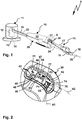
- a hand-held power tool 10 forms an exemplary electrical device 9, which is switchable with a switch 30.
- the hand-held power tool 10 has, for example, a housing designed as a machining head 11, in which an electric drive motor 12 is arranged.
- the drive motor 12 drives directly or via a gear, not shown, a tool holder 14 to which a machining tool 13 is releasably fastened.
- the handle member 15 From the processing head 11 is a handle member 15 from which can be grasped by an operator.
- the handle member 15 includes, for example, a handle bar with bar sections 16 and 17 that can be gripped or grasped by an operator.
- the rod portion 16 is fixed or articulated via a hinge assembly, not shown, in particular gimbal, with connected to the processing head 11.
- the machining head 11 can move relative to the handle member 16 so that it can be conveniently guided along a surface to be machined.
- the hand-held machine tool 10 is designed as a ceiling or wall grinder.
- an electrical connection 18 for an electrical power supply of the hand-held power tool 10 is provided.
- a power supply cable 26 can be connected to the connection 18 for connection to an electrical power supply network.
- a mobile energy storage for example a battery pack, for powering the hand-held power tool 10 would be readily possible.
- the switch 30 From the terminal 18 lead electrical lines 24 to the switch 30, with which the drive motor 12 can be turned on or off.
- the switch 30 is connected via lines 21 to a power supply device 22, which in turn is connected via lines 23 to the drive motor 12 to its power supply.
- the switch 30 is received, for example, in a switch receptacle 25 of a handle housing 20, which is arranged between the bar sections 16 and 17.
- the switch 30 may be conveniently operated by a user grasping the rod portion 17, that is, grasping the hand-held power tool 10 at a handle portion with a finger, in particular, his or her thumb or forefinger. In this case, a special operating safety is given, namely because measures against unintentional switching on the hand-held machine tool 10 are made, but this is still easily switchable.
- a contact arrangement 35 with electrical contacts 34, 36 is arranged, which are switchable between a closed position E and a switch-off position A, wherein they are in the closed position E are in electrical contact with each other.
- the contacts 34, 36 each comprise pairs of contacts, ie in each case two electrical surfaces, in particular contact lugs, which can be actuated by a sliding member 37. It is understood that one of the contact pairs 34 or 36 is completely sufficient to turn on or off the power supply device 22 and / or the drive motor 12.
- the second contact pair can serve, for example, as a redundant contact pair or security contact pair.
- a spring 38 adjusts the sliding member 37 in a position in which the contacts 34, 36 are electrically isolated from each other, so take the switch-off position A.
- the contacts 34, 36 and the slide member 37 are housed protected or housed protected in a housing 33 of the contact assembly 35.
- the housing 33 is advantageously at least dust-tight, expediently also at least partially sealed against moisture.
- the sliding member 37 is in a sealed guide and / or below a cover 37A, for example made of elastic plastic or rubber.
- the cover 37A is designed, for example, in the manner of a protective hood, but allows a displaceability of the sliding member 37 along an adjusting axis, for example for a switch-on movement SE.
- the contact arrangement 35 can be actuated by an actuating arrangement 60 in the closed position E.
- the actuating arrangement 60 does not act on the sliding member 37, so that it can be actuated by the spring 38 in the direction of the switch-off position A, in which the contacts 34, 36 are not connected to each other.
- the power supply device 22 has a logic circuit, so that, for example, when the contacts 34, 36 are separated or at least one of the pairs of contacts 34, 36, which serves to switch the power supply device 22, in the closed position E from each other having separate electrical contacts, these Switch position interpreted as switch-on position.
- the switch base 31 has, for the housing 33 of the contact arrangement 35, a receptacle which is provided, for example, on a base body 32 of the switch base 31.
- a bearing receptacle 39 for a pivot bearing of an actuator 61 of the actuator assembly 60, namely for an actuator bearing 71 is provided on the switch base 31.
- the actuator 61 pivots about a pivot axis S1 of the actuator bearing 71 between an inactive position IS ( FIGS. 3, 4 ) via an intermediate position Z away in an active position AS, wherein the actuator 61, the slide member 37, thus an actuator of the contact assembly 35, actuated from the open position A in the closed position E.
- the actuator 61 can be locked by a locking element 62 in the active position AS and in the inactive position IS.
- the contact arrangement 35 or the switch 30 as a whole in the closed position E and the open position A can be locked.
- the locking element 62 in turn is mounted on the actuator 71 pivotally about a pivot axis S2 based on a locking element bearing 72. By a pivoting movement about the pivot axis S2, the locking element 62 can be adjusted from a locking position to an unlocked position. Since an unlocking position and a locking position are possible both in the switch-on position E and in the switch-off position A, the locking element 62 can be adjusted so that the switch 30 is a switch-off locking position AV occupies ( FIG. 3 ) from which the switch 30 can be unlocked, so that it assumes a switch-off unlocking position AE. For example, an operator actuates an actuation portion 76 of an actuation surface 74 on the latch member 62.
- the operator presses an actuation force 73 in an unlock actuation direction P1 and / or along an unlock actuation axis or actuation trajectory A1 on an actuation arm 73 projecting from the pivot axis S2 in which the actuating surface 74 is arranged at least in sections, namely with its actuating portion 76, in order to adjust the locking element 62 from the switch-off locking position AV to the switch-off unlocking position AE.
- the locking element 62 pivots about the pivot axis S2.
- a locking projection 80 of the locking element 62 is disengaged from a locking contour 42 on the switch base 31.
- the locking projection 80 has, for example, a rear engagement surface 81, which is supported on the locking contour 42 configured, for example, as a recess or as a projection in the locking position.
- the locking projection 80 is provided for example on a locking arm 75, which is an extension of the actuating arm 73, so to speak.
- the locking projection 80 projects, for example, toward the pivot axis S1 and / or S2 in front of the locking arm 75.
- the locking projection 80 is provided at a free end portion of the lock arm 75.
- the actuating arm 73 and the locking arm 75 are, for example, components of an approximately arcuately extending about the pivot axis S1 actuating body 82nd
- the contact arrangement 35 is in the switch-off unlocking position AE in the switch-off position A.
- the actuating arrangement 60 and therefore the contact arrangement 35 or the switch 30 can, however, starting from this position via an intermediate position Z (FIG. FIG. 5 ) are adjusted to the switch-on position E.
- the operator presses, for example, according to a switching actuation direction P2 and / or along a switching actuation path A2 or switching actuation axis to a switching actuation portion 77 of the actuation surface 74 approximately tangentially to the pivot axis S1 and / or to the pivot axis S2, whereby the locking element 62 together with the actuator 61 pivots about the pivot axis S1.
- FIG. 5 By way of example, the intermediate position Z during this adjustment path between the switch-off position A and the switch-on position E is shown.
- the locking projection 80 is pivoted past a locking contour 43 assigned to the switch-on position E ( FIG. 6 ) and then takes a switch-off unlocking AE a.
- the locking contour 43 is for example as a locking receptacle or recess ( FIG. 2 ) designed.
- the locking contour 43 is easily recognizable by the operator.
- a guide portion 44 is expediently provided, on which the locking projection 80 can slide during the adjustment of the actuating arrangement 60 between the active position AS and the inactive position IS along.
- the actuating arrangement 60 can not be locked in these intermediate positions, the switch 30 is accordingly adjustable.
- the locking projection 80 engages with the locking contour 43, so that the locking element 62 and thus the switch 30 as a whole is locked in the closed position E and the switch-on Locking position EV takes ( FIG. 7 ).
- the drive motor 12 is permanently energized, ie the hand-held power tool 10 is, so to speak, in a continuous operating position.
- the switch 30 is unlocked by a simple unlocking of the actuator body 82 or the locking element 62 by pressing the unlocking operation portion 76 and then by another operation in an angular, for example, approximately right-angled force direction, from the open position A in the Closed position E is adjusted.
- a trough 83 is provided, into which a finger or a fingertip of a finger of a hand of the operator can engage comfortably.
- the operator can first act on the locking element 62 in a direction of force corresponding to the unlocking actuating direction P1 and then in a direction of force corresponding to the switching actuating direction P2 in order to first unlock the switch 30 and then to the closed position E. adjust.
- the switch-off position A and the switch-on position E are visually displayed to the operator by a marking 84 on the actuating body 82.
- the marking 84 contains, for example, a symbol 0 for the switch-off position A and a symbol I for the switch-on position E.
- the marking 84 is preferably visually clearly visible directly next to the actuating surface 74, in particular on the locking arm 75.
- a springs or spring arrangements are provided:
- the actuator 61 acts with an actuating contour 65 on the slide member 37 of the contact assembly 35.
- the slide member 37 is acted upon opposite to this direction of actuation by the spring 38, so that the slide member 37 actuates the actuator 61 from the active position AS in the direction of the inactive position IS.
- the locking element 62 tends so to speak to an automatic locking. It is in fact received by a spring 69 which is received in a spring receiver 68 is loaded in the direction of a respective locking position EV or AV.
- the spring receptacle 68 is located, for example, on a pivot arm 63 of the actuator 61, which protrudes from a bearing portion 64 of the actuator 61.
- the spring receptacle 68 is provided, for example, in a housing 67, which protrudes from the pivot arm 63, in particular in the direction of the contact arrangement 35 or the sliding member 37.
- the actuating contour 65 is provided on an outer side of a bottom wall of the housing 67, on which the spring 69 is supported with respect to the actuator 61.
- the spring 69 is further supported on a spring arm 79, the angle from the actuator body 82, for example, approximately at right angles or at an angle of 80-110 °, protrudes.
- a bearing receptacle 78 of the locking element bearing 72 is provided on the spring arm 79.
- the bearing receptacle 78 is expediently located on a foot region or transition region between the spring arm 79 and the actuating body 82 of the locking element 62.
- the spring arm 79 pivots about the pivot axis S2 (as a curved arrow in FIG. 6 drawn), if it is represented by an R restoring force (as arrow in FIG. 6 drawn) of the spring 69 is loaded in the direction of one of the two locking position in AV or EV.
- the locking projection 80 is loaded by the spring 69 in the direction of a locking position, ie in the direction of engagement in the locking contours 42 or 43.
- the locking element bearing 72 is located at a free end region 66 of the pivot arm 69.
- the actuating body 82 thus pivots on the free end region 66 of the pivot arm 69.
- the locking element 62 is also guided on a guide slot 40.
- the spring arm 79 in particular in the area of the bearing receptacle 78 (a another location would be possible) guided on the guide slot 40.
- the spring arm 79 or the locking element 62 passes through a corresponding guide slot 48, which forms the guide slot 40 or a part thereof.
- the switch-off position A is also assigned an end stop 41.
- the end stop 41 is, for example, a longitudinal end portion or a longitudinal end of the guide slot 40, on which the spring arm 79 in the position according to FIG. 3 , ie in the off-unlocking position AE or the off-lock position AV abuts.
- the operation of the power-off machine switch 30 proceeds as follows: the operator makes an unlocking movement by pressing the unlock operation portion 76 in the unlock operation direction P1, thereby disengaging the lock projection 80 Engagement with the locking contour 43 passes.
- the spring 69 is tensioned, namely because the spring arm 79 presses on the spring 69.
- the thus unlocked switch 30 can be brought into the open position A, for example, by the spring 37, the actuator 61 and together with this the locking element 61 in the direction inactive position IS adjusted.
- the operator can operate the switch 30 by a corresponding additional application of force in the sense of pulling or pressing in the direction of the inactive position IS in the direction of the switch-off position A (counter to the switch actuating direction P2).
- it helps a corrugation or other structuring 85 on the actuating surface 74.
- the structuring 85 also supports when adjusting the switch 30 from the open position A in the direction of the closed position E.
- the main body 32 of the switch base 31 is preferably in two parts.
- it consists of two half-shell-like designed housing parts 45 and / or a housing 46th
- the guide slot 48 of the guide slot 40 may be formed or arranged.
- portions 49 of the housing parts 45 form a total of a cover 47, on which the guide slot 48 is arranged.
- the cover 47 may also be formed by at least one wall surface which does not form part of a housing.
- the cover 47 need not be in two parts, but could also be one-piece, if a corresponding guide slot or a passage opening for the locking element is present.
- the cover 47 is in fact penetrated by the locking element 62, wherein the actuator 61 and on the other hand the actuating surface 74 are arranged on opposite sides on the one hand.
- the cover 47 covers, so to speak, the actuator 61, which is arranged in the interior of the housing 46 of the switch 30 and / or in the interior of the hand-held power tool 10, that is, in the interior of the housing 11. Only the outside of the cover 47 protruding components of the locking element 62, in particular the actuating arm 73 and the locking arm 75, are visible to the operator and operable. As a result, in particular the mechanical components of the switch 30 are protected, while the components and contours of the switch 30 necessary for the operation are easily graspable and / or actuatable by the operator.
- the bearings 71, 72 have, inter alia, the bearing receptacle 39, 78 and other unspecified bearing receptacles of the respective other element of the actuator 61 and locking element 62. In these bearing bolts unspecified or other Lagerachsisse are also pivotally added.
Claims (15)
- Interrupteur pour un appareil électrique (9) sous la forme d'une machine-outil portative (10), d'une machine-outil de table mobile ou d'un aspirateur ou en tant que composant d'un tel appareil électrique (9), dans lequel l'interrupteur (30) présente un agencement de contact (35) présentant des contacts électriques (34, 36), réglable par un dispositif d'actionnement (60) entre une position fermée (E) prévue pour le fonctionnement de l'appareil électrique (9) et une position ouverte (A) prévue pour la mise hors tension de l'appareil électrique (9), dans lequel l'agencement d'actionnement (60) présente une surface d'actionnement (74) pour un actionnement manuel par un opérateur, dans lequel l'agencement d'actionnement (60) présente un organe de réglage (61) logé de manière réglable au niveau d'une base d'interrupteur (31) de l'interrupteur (30) à l'aide d'un palier d'organe de réglage (71) pour le réglage de l'agencement de contact (35) entre la position fermée (E) et la position ouverte (A) et un élément de verrouillage (62) réglable au niveau de l'organe de réglage (61) à l'aide d'un palier d'élément de verrouillage (72) par rapport à l'organe de réglage (61), à l'aide duquel l'organe de réglage (61) est verrouillable dans une position active (AS) associée à la position fermée (E) et/ou dans une position inactive (IS) associée à la position ouverte (A), caractérisé en ce que l'organe de réglage (61) est réglable par l'opérateur entre la position inactive (IS) et la position active (AS) exclusivement à l'aide de l'élément de verrouillage (62) formant un élément d'actionnement.
- Interrupteur selon la revendication 1, caractérisé en ce que l'élément de verrouillage (62) forme un élément d'actionnement, en particulier exclusif ou unique, pour le réglage de l'organe de réglage (61) entre la position active (AS) et la position inactive (IS) et présente la surface d'actionnement (74).
- Interrupteur selon la revendication 1 ou 2, caractérisé en ce que le palier d'élément de verrouillage (72) et/ou le palier d'organe de réglage (71) comprend ou est un palier pivotant et/ou que le palier d'élément de verrouillage (72) et/ou le palier d'organe de réglage (71) présente au moins un élément d'axe de palier et un logement de palier (78) pour le logement pivotant de l'élément d'axe de palier et/ou une section de liaison souple en flexion entre les composants reliés les uns aux autres de manière mobile par le palier ou est ainsi formé.
- Interrupteur selon l'une quelconque des revendications précédentes, caractérisé en ce que l'organe de réglage (61) est pivotant par rapport à la base d'interrupteur (31) autour d'un premier axe de pivotement (S1) et l'élément de verrouillage (62) est pivotant par rapport à l'organe de réglage (61) autour d'un deuxième axe de pivotement (S2), dans lequel le premier axe de pivotement (S1) et le deuxième axe de pivotement (S2) sont parallèles l'un à l'autre de manière appropriée.
- Interrupteur selon l'une quelconque des revendications précédentes, caractérisé en ce que l'organe de réglage (61) présente un bras pivotant faisant saillie du palier d'organe de réglage (71), au niveau duquel l'élément de verrouillage (62) est logé mobile à l'aide du palier d'élément de verrouillage (72) et/ou l'élément de verrouillage (62) et l'organe de réglage (61) forment une configuration en forme de T.
- Interrupteur selon l'une quelconque des revendications précédentes, caractérisé en ce qu'une direction d'actionnement de déverrouillage (P1) ou voie d'actionnement de déverrouillage (A1) pour le réglage de l'élément de verrouillage (62) d'une position de verrouillage (AV, EV) verrouillant l'organe de réglage (61) à une position de déverrouillage (AE, EE) prévue pour le réglage de l'organe de réglage (61) et une direction d'actionnement de commutation (P2) ou voie d'actionnement de déverrouillage (A2) pour le réglage de l'organe de réglage (61) entre la position ouverte (A) et la position fermée (E) forment un angle l'une par rapport à l'autre, sont en particulier à peu près à angle droit, et/ou la direction d'actionnement de commutation (P2) ou voie d'actionnement de commutation (A2) s'étend de manière tangentielle ou en forme d'arc autour d'un axe de pivotement (S2) du palier d'organe de réglage (71) et la direction d'actionnement de déverrouillage (P1) ou voie d'actionnement de déverrouillage (A1) s'étend à peu près radialement par rapport à un axe de pivotement (S1, S2) du palier d'élément de verrouillage (72) et/ou du palier d'organe de réglage (71) ou parallèlement à une ligne radiale, qui s'éloigne de l'axe de pivotement (S1, S2).
- Interrupteur selon l'une quelconque des revendications précédentes, caractérisé en ce que la surface d'actionnement (74) présente une section d'actionnement de déverrouillage (76) associée au déverrouillage de l'élément de verrouillage (62) et une section d'actionnement de commutation (77) associée au réglage de l'organe de réglage (61) dans la position active (AS) et/ou position inactive (IS), dans lequel il est prévu de manière avantageuse que la section d'actionnement de déverrouillage (76) et la section d'actionnement de commutation (77) forment un angle l'une par rapport à l'autre et/ou forment des sections d'un creux (83) et/ou se trouvent latéralement à côté d'un creux (83).
- Interrupteur selon l'une quelconque des revendications précédentes, caractérisé en ce que la surface d'actionnement (74) présente une section d'actionnement de commutation (77) associée au réglage de l'organe de réglage (61) dans la position active (AS) et/ou la position inactive (IS), dans lequel la section d'actionnement de commutation (77) est orientée radialement ou sensiblement radialement par rapport à un axe de pivotement (S1, S2) du palier d'élément de verrouillage (72) et/ou du palier d'organe de réglage (71) et/ou est orientée de sorte qu'une force d'actionnement agissant sur la section d'actionnement de commutation (77) agit pour le réglage de l'organe de réglage (61) dans la position active (AS) et/ou la position inactive (IS) dans le sens d'un réglage de l'élément de verrouillage (62) dans une position de verrouillage (AV, EV) verrouillant l'organe de réglage (61) dans la position active (AS) ou la position inactive (IS).
- Interrupteur selon l'une quelconque des revendications précédentes, caractérisé en ce que l'élément de verrouillage (62) est sollicité par un agencement de ressort s'appuyant en particulier sur l'organe de réglage (61) et sur l'élément de verrouillage (62) dans une position de verrouillage (AV, EV) verrouillant l'organe de réglage (61) et/ou que l'élément de verrouillage (62) présente un bras ressort (79) s'appuyant sur le ou un agencement de ressort et un bras d'actionnement (73) présentant la surface d'actionnement (74), entre lesquels le palier d'élément de verrouillage (72) est agencé.
- Interrupteur selon l'une quelconque des revendications précédentes, caractérisé en ce que l'organe de réglage (61) est sollicité par un ressort (38) formant en particulier un composant de l'agencement de contact (35) en direction de la position inactive (IS) et/ou que l'agencement de contact (35) présente un organe d'actionnement, en particulier organe coulissant ou organe d'actionnement par pression, qui est coulissant ou peut être pivoté par l'organe de réglage (61) en direction de la position fermée (E) de l'agencement de contact (35).
- Interrupteur selon l'une quelconque des revendications précédentes, caractérisé en ce qu'au moins un contour de verrouillage (42, 43), dans lequel l'élément de verrouillage (62) entre en prise dans une position de verrouillage (AV, EV) verrouillant l'organe de réglage (61) dans la position active (AS) ou la position inactive (IS), est agencé au niveau d'une zone extérieure visible par l'opérateur de la base d'interrupteur (31) ou d'un boîtier (11, 46) de la machine-outil portative (10) ou de l'interrupteur (30) et/ou que l'organe de réglage (61) est recouvert par un recouvrement (47) de manière au moins sensiblement non visible pour l'opérateur, dans lequel l'organe de réglage (61) et une surface d'actionnement (74) de l'élément de verrouillage (62) actionnable par l'opérateur sont agencés sur des côtés opposés l'un à l'autre du recouvrement (47).
- Interrupteur selon l'une quelconque des revendications précédentes, caractérisé en ce que la base d'interrupteur (31) présente une coulisse de guidage (40) pour le guidage de l'élément de verrouillage (62) et/ou de l'organe de réglage (61).
- Interrupteur selon la revendication 12, caractérisé en ce qu'au niveau de la coulisse de guidage (40) est agencé au moins un contour de verrouillage (42, 43), dans lequel l'élément de verrouillage (62) entre en prise dans une position de verrouillage (AV, EV) verrouillant l'organe de réglage (61) dans la position active (AS) ou position inactive (IS), et/ou au moins une butée d'extrémité (41), contre laquelle l'élément de verrouillage (62) et/ou l'organe de réglage (61) vient buter dans une position de réglage associée à la position active (AS) ou à la position inactive (IS) de l'organe de réglage (61).
- Interrupteur selon la revendication 12 ou 13, caractérisé en ce que la coulisse de guidage (40) s'étend en forme d'arc ou d'anneau circulaire autour d'un axe de pivotement (S1) du palier d'organe de réglage (71) et/ou l'élément de verrouillage (62) traverse la coulisse de guidage (40) et/ou le palier d'élément de verrouillage (72) est guidé dans la coulisse de guidage (40) et/ou la coulisse de guidage présente une fente de guidage (48), qui est traversée par l'élément de verrouillage (62).
- Machine-outil portative (10), en particulier ponceuse, avec un interrupteur (30) selon l'une quelconque des revendications précédentes ainsi qu'un moteur d'entraînement (12) commutable par l'interrupteur (30).
Applications Claiming Priority (1)
| Application Number | Priority Date | Filing Date | Title |
|---|---|---|---|
| DE102016104213 | 2016-03-08 |
Publications (2)
| Publication Number | Publication Date |
|---|---|
| EP3217412A1 EP3217412A1 (fr) | 2017-09-13 |
| EP3217412B1 true EP3217412B1 (fr) | 2019-03-20 |
Family
ID=58185356
Family Applications (1)
| Application Number | Title | Priority Date | Filing Date |
|---|---|---|---|
| EP17158010.3A Active EP3217412B1 (fr) | 2016-03-08 | 2017-02-24 | Interrupteur pour une machine-outil portative |
Country Status (2)
| Country | Link |
|---|---|
| EP (1) | EP3217412B1 (fr) |
| DE (1) | DE102017103964A1 (fr) |
Families Citing this family (3)
| Publication number | Priority date | Publication date | Assignee | Title |
|---|---|---|---|---|
| EP3552760A1 (fr) * | 2018-04-09 | 2019-10-16 | HILTI Aktiengesellschaft | Commutateur pour appareil de meulage et logique de commutation |
| EP3812089A1 (fr) | 2019-10-23 | 2021-04-28 | Black & Decker Inc. | Ponceuse à manche |
| US11867224B2 (en) | 2021-01-27 | 2024-01-09 | Black & Decker Inc. | Locking mechanism for two telescoping poles of a power tool |
Family Cites Families (4)
| Publication number | Priority date | Publication date | Assignee | Title |
|---|---|---|---|---|
| US4006334A (en) * | 1975-03-17 | 1977-02-01 | Mcgraw-Edison Company | Safety switch for power tool |
| DE29514330U1 (de) * | 1995-09-07 | 1995-11-02 | Atlas Copco Elektrowerkzeuge | Betätigungsvorrichtung für einen Schalter einer Werkzeugmaschine |
| US5577600A (en) * | 1995-11-21 | 1996-11-26 | Emerson Electric Co. | Switch lock-out device for power tool |
| EP2884515A1 (fr) * | 2013-12-16 | 2015-06-17 | HILTI Aktiengesellschaft | Commutateur d'appareil pour outils électriques avec blocage du commutateur |
-
2017
- 2017-02-24 EP EP17158010.3A patent/EP3217412B1/fr active Active
- 2017-02-24 DE DE102017103964.3A patent/DE102017103964A1/de active Pending
Non-Patent Citations (1)
| Title |
|---|
| None * |
Also Published As
| Publication number | Publication date |
|---|---|
| EP3217412A1 (fr) | 2017-09-13 |
| DE102017103964A1 (de) | 2017-09-14 |
Similar Documents
| Publication | Publication Date | Title |
|---|---|---|
| DE19546328B4 (de) | Handwerkzeugmaschine mit einem drehbaren Handgriff | |
| DE19938523B4 (de) | Beweglicher Handgriff für ein angetriebenes Handwerkzeug | |
| DE60005074T2 (de) | Batteriebetriebene Handwerkzeugmaschine | |
| EP1075905B1 (fr) | Marteau electrique à main | |
| DE69937377T2 (de) | Sperrmechanismus für kraftbetriebenes Werkzeug | |
| EP2101340B1 (fr) | Commutateur électrique, notamment commutateur d'outil électrique | |
| EP3217412B1 (fr) | Interrupteur pour une machine-outil portative | |
| DE202010008031U1 (de) | Verriegelungs-Schaltervorrichtung für ein Kraftwerkzeug | |
| DE102014214982A1 (de) | Elektrowerkzeugmaschine | |
| DE2548656A1 (de) | Verriegelungseinrichtung fuer einen schalter eines elektrischen geraetes | |
| WO2006024560A1 (fr) | Outil electrique a double interrupteur | |
| DE102008056563B4 (de) | Elektrowerkzeug, insbesondere Säge | |
| EP2881229B1 (fr) | Machine-outil manuelle dotée d'un dispositif de sécurisation | |
| DE60316633T2 (de) | Ausverriegelung für Schalter von Werkzeugen | |
| EP1062673B1 (fr) | Commutateur electrique | |
| DE60100298T2 (de) | Pflanzenschneidevorrichtung | |
| EP2140466B1 (fr) | Prise électrique | |
| EP0718859A1 (fr) | Dispositif pour la commutation d'un moteur électrique, en particulier pour le freinage d'un outil électrique | |
| EP2846346A2 (fr) | Élément de blocage pour un commutateur électrique | |
| DE19958297B4 (de) | Elektrowerkzeug mit verbesserter Schaltervorrichtung | |
| DE602004002438T2 (de) | Abriegelungsmechanismus für eine schwenkbare Griffanordnung eines Kraftwerkzeugs | |
| DE602004000897T2 (de) | Betätigungsmechanismus für ein Kraftwerkzeug | |
| DE602004001103T2 (de) | Abriegelungsmechanismus für eine schwenkbare Griffanordnung eines Kraftwerkzeugs | |
| DE4421746A1 (de) | Motorisch angetriebene Heckenschere mit Zweihand-Sicherheitsbedienung | |
| DE102021213886A1 (de) | Handgehaltenes Elektrorotationswerkzeug |
Legal Events
| Date | Code | Title | Description |
|---|---|---|---|
| PUAI | Public reference made under article 153(3) epc to a published international application that has entered the european phase |
Free format text: ORIGINAL CODE: 0009012 |
|
| STAA | Information on the status of an ep patent application or granted ep patent |
Free format text: STATUS: THE APPLICATION HAS BEEN PUBLISHED |
|
| AK | Designated contracting states |
Kind code of ref document: A1 Designated state(s): AL AT BE BG CH CY CZ DE DK EE ES FI FR GB GR HR HU IE IS IT LI LT LU LV MC MK MT NL NO PL PT RO RS SE SI SK SM TR |
|
| AX | Request for extension of the european patent |
Extension state: BA ME |
|
| STAA | Information on the status of an ep patent application or granted ep patent |
Free format text: STATUS: REQUEST FOR EXAMINATION WAS MADE |
|
| 17P | Request for examination filed |
Effective date: 20180306 |
|
| RBV | Designated contracting states (corrected) |
Designated state(s): AL AT BE BG CH CY CZ DE DK EE ES FI FR GB GR HR HU IE IS IT LI LT LU LV MC MK MT NL NO PL PT RO RS SE SI SK SM TR |
|
| GRAP | Despatch of communication of intention to grant a patent |
Free format text: ORIGINAL CODE: EPIDOSNIGR1 |
|
| STAA | Information on the status of an ep patent application or granted ep patent |
Free format text: STATUS: GRANT OF PATENT IS INTENDED |
|
| RIC1 | Information provided on ipc code assigned before grant |
Ipc: H01H 21/50 20060101ALN20180926BHEP Ipc: H01H 9/22 20060101ALN20180926BHEP Ipc: H01H 9/06 20060101AFI20180926BHEP Ipc: H01H 13/08 20060101ALI20180926BHEP Ipc: H01H 3/20 20060101ALI20180926BHEP |
|
| INTG | Intention to grant announced |
Effective date: 20181017 |
|
| GRAJ | Information related to disapproval of communication of intention to grant by the applicant or resumption of examination proceedings by the epo deleted |
Free format text: ORIGINAL CODE: EPIDOSDIGR1 |
|
| STAA | Information on the status of an ep patent application or granted ep patent |
Free format text: STATUS: REQUEST FOR EXAMINATION WAS MADE |
|
| GRAR | Information related to intention to grant a patent recorded |
Free format text: ORIGINAL CODE: EPIDOSNIGR71 |
|
| GRAS | Grant fee paid |
Free format text: ORIGINAL CODE: EPIDOSNIGR3 |
|
| STAA | Information on the status of an ep patent application or granted ep patent |
Free format text: STATUS: GRANT OF PATENT IS INTENDED |
|
| INTC | Intention to grant announced (deleted) | ||
| GRAA | (expected) grant |
Free format text: ORIGINAL CODE: 0009210 |
|
| STAA | Information on the status of an ep patent application or granted ep patent |
Free format text: STATUS: THE PATENT HAS BEEN GRANTED |
|
| RIC1 | Information provided on ipc code assigned before grant |
Ipc: H01H 9/22 20060101ALN20190111BHEP Ipc: H01H 21/50 20060101ALN20190111BHEP Ipc: H01H 13/08 20060101ALI20190111BHEP Ipc: H01H 3/20 20060101ALI20190111BHEP Ipc: H01H 9/06 20060101AFI20190111BHEP |
|
| INTG | Intention to grant announced |
Effective date: 20190118 |
|
| AK | Designated contracting states |
Kind code of ref document: B1 Designated state(s): AL AT BE BG CH CY CZ DE DK EE ES FI FR GB GR HR HU IE IS IT LI LT LU LV MC MK MT NL NO PL PT RO RS SE SI SK SM TR |
|
| REG | Reference to a national code |
Ref country code: GB Ref legal event code: FG4D Free format text: NOT ENGLISH |
|
| REG | Reference to a national code |
Ref country code: SE Ref legal event code: TRGR |
|
| REG | Reference to a national code |
Ref country code: CH Ref legal event code: EP |
|
| REG | Reference to a national code |
Ref country code: DE Ref legal event code: R096 Ref document number: 502017000941 Country of ref document: DE |
|
| REG | Reference to a national code |
Ref country code: AT Ref legal event code: REF Ref document number: 1111347 Country of ref document: AT Kind code of ref document: T Effective date: 20190415 |
|
| REG | Reference to a national code |
Ref country code: IE Ref legal event code: FG4D Free format text: LANGUAGE OF EP DOCUMENT: GERMAN |
|
| REG | Reference to a national code |
Ref country code: NL Ref legal event code: FP |
|
| PG25 | Lapsed in a contracting state [announced via postgrant information from national office to epo] |
Ref country code: LT Free format text: LAPSE BECAUSE OF FAILURE TO SUBMIT A TRANSLATION OF THE DESCRIPTION OR TO PAY THE FEE WITHIN THE PRESCRIBED TIME-LIMIT Effective date: 20190320 Ref country code: NO Free format text: LAPSE BECAUSE OF FAILURE TO SUBMIT A TRANSLATION OF THE DESCRIPTION OR TO PAY THE FEE WITHIN THE PRESCRIBED TIME-LIMIT Effective date: 20190620 |
|
| REG | Reference to a national code |
Ref country code: LT Ref legal event code: MG4D |
|
| PG25 | Lapsed in a contracting state [announced via postgrant information from national office to epo] |
Ref country code: RS Free format text: LAPSE BECAUSE OF FAILURE TO SUBMIT A TRANSLATION OF THE DESCRIPTION OR TO PAY THE FEE WITHIN THE PRESCRIBED TIME-LIMIT Effective date: 20190320 Ref country code: HR Free format text: LAPSE BECAUSE OF FAILURE TO SUBMIT A TRANSLATION OF THE DESCRIPTION OR TO PAY THE FEE WITHIN THE PRESCRIBED TIME-LIMIT Effective date: 20190320 Ref country code: GR Free format text: LAPSE BECAUSE OF FAILURE TO SUBMIT A TRANSLATION OF THE DESCRIPTION OR TO PAY THE FEE WITHIN THE PRESCRIBED TIME-LIMIT Effective date: 20190621 Ref country code: LV Free format text: LAPSE BECAUSE OF FAILURE TO SUBMIT A TRANSLATION OF THE DESCRIPTION OR TO PAY THE FEE WITHIN THE PRESCRIBED TIME-LIMIT Effective date: 20190320 Ref country code: BG Free format text: LAPSE BECAUSE OF FAILURE TO SUBMIT A TRANSLATION OF THE DESCRIPTION OR TO PAY THE FEE WITHIN THE PRESCRIBED TIME-LIMIT Effective date: 20190620 |
|
| PG25 | Lapsed in a contracting state [announced via postgrant information from national office to epo] |
Ref country code: EE Free format text: LAPSE BECAUSE OF FAILURE TO SUBMIT A TRANSLATION OF THE DESCRIPTION OR TO PAY THE FEE WITHIN THE PRESCRIBED TIME-LIMIT Effective date: 20190320 Ref country code: PT Free format text: LAPSE BECAUSE OF FAILURE TO SUBMIT A TRANSLATION OF THE DESCRIPTION OR TO PAY THE FEE WITHIN THE PRESCRIBED TIME-LIMIT Effective date: 20190720 Ref country code: ES Free format text: LAPSE BECAUSE OF FAILURE TO SUBMIT A TRANSLATION OF THE DESCRIPTION OR TO PAY THE FEE WITHIN THE PRESCRIBED TIME-LIMIT Effective date: 20190320 Ref country code: RO Free format text: LAPSE BECAUSE OF FAILURE TO SUBMIT A TRANSLATION OF THE DESCRIPTION OR TO PAY THE FEE WITHIN THE PRESCRIBED TIME-LIMIT Effective date: 20190320 Ref country code: CZ Free format text: LAPSE BECAUSE OF FAILURE TO SUBMIT A TRANSLATION OF THE DESCRIPTION OR TO PAY THE FEE WITHIN THE PRESCRIBED TIME-LIMIT Effective date: 20190320 Ref country code: SK Free format text: LAPSE BECAUSE OF FAILURE TO SUBMIT A TRANSLATION OF THE DESCRIPTION OR TO PAY THE FEE WITHIN THE PRESCRIBED TIME-LIMIT Effective date: 20190320 Ref country code: AL Free format text: LAPSE BECAUSE OF FAILURE TO SUBMIT A TRANSLATION OF THE DESCRIPTION OR TO PAY THE FEE WITHIN THE PRESCRIBED TIME-LIMIT Effective date: 20190320 |
|
| PG25 | Lapsed in a contracting state [announced via postgrant information from national office to epo] |
Ref country code: SM Free format text: LAPSE BECAUSE OF FAILURE TO SUBMIT A TRANSLATION OF THE DESCRIPTION OR TO PAY THE FEE WITHIN THE PRESCRIBED TIME-LIMIT Effective date: 20190320 Ref country code: PL Free format text: LAPSE BECAUSE OF FAILURE TO SUBMIT A TRANSLATION OF THE DESCRIPTION OR TO PAY THE FEE WITHIN THE PRESCRIBED TIME-LIMIT Effective date: 20190320 |
|
| PG25 | Lapsed in a contracting state [announced via postgrant information from national office to epo] |
Ref country code: IS Free format text: LAPSE BECAUSE OF FAILURE TO SUBMIT A TRANSLATION OF THE DESCRIPTION OR TO PAY THE FEE WITHIN THE PRESCRIBED TIME-LIMIT Effective date: 20190720 |
|
| REG | Reference to a national code |
Ref country code: DE Ref legal event code: R097 Ref document number: 502017000941 Country of ref document: DE |
|
| PLBE | No opposition filed within time limit |
Free format text: ORIGINAL CODE: 0009261 |
|
| STAA | Information on the status of an ep patent application or granted ep patent |
Free format text: STATUS: NO OPPOSITION FILED WITHIN TIME LIMIT |
|
| PG25 | Lapsed in a contracting state [announced via postgrant information from national office to epo] |
Ref country code: DK Free format text: LAPSE BECAUSE OF FAILURE TO SUBMIT A TRANSLATION OF THE DESCRIPTION OR TO PAY THE FEE WITHIN THE PRESCRIBED TIME-LIMIT Effective date: 20190320 |
|
| 26N | No opposition filed |
Effective date: 20200102 |
|
| PG25 | Lapsed in a contracting state [announced via postgrant information from national office to epo] |
Ref country code: SI Free format text: LAPSE BECAUSE OF FAILURE TO SUBMIT A TRANSLATION OF THE DESCRIPTION OR TO PAY THE FEE WITHIN THE PRESCRIBED TIME-LIMIT Effective date: 20190320 |
|
| PG25 | Lapsed in a contracting state [announced via postgrant information from national office to epo] |
Ref country code: TR Free format text: LAPSE BECAUSE OF FAILURE TO SUBMIT A TRANSLATION OF THE DESCRIPTION OR TO PAY THE FEE WITHIN THE PRESCRIBED TIME-LIMIT Effective date: 20190320 |
|
| REG | Reference to a national code |
Ref country code: CH Ref legal event code: PL |
|
| REG | Reference to a national code |
Ref country code: BE Ref legal event code: MM Effective date: 20200229 |
|
| PG25 | Lapsed in a contracting state [announced via postgrant information from national office to epo] |
Ref country code: MC Free format text: LAPSE BECAUSE OF FAILURE TO SUBMIT A TRANSLATION OF THE DESCRIPTION OR TO PAY THE FEE WITHIN THE PRESCRIBED TIME-LIMIT Effective date: 20190320 Ref country code: LU Free format text: LAPSE BECAUSE OF NON-PAYMENT OF DUE FEES Effective date: 20200224 |
|
| PG25 | Lapsed in a contracting state [announced via postgrant information from national office to epo] |
Ref country code: CH Free format text: LAPSE BECAUSE OF NON-PAYMENT OF DUE FEES Effective date: 20200229 Ref country code: LI Free format text: LAPSE BECAUSE OF NON-PAYMENT OF DUE FEES Effective date: 20200229 |
|
| PG25 | Lapsed in a contracting state [announced via postgrant information from national office to epo] |
Ref country code: IE Free format text: LAPSE BECAUSE OF NON-PAYMENT OF DUE FEES Effective date: 20200224 |
|
| PG25 | Lapsed in a contracting state [announced via postgrant information from national office to epo] |
Ref country code: BE Free format text: LAPSE BECAUSE OF NON-PAYMENT OF DUE FEES Effective date: 20200229 |
|
| PG25 | Lapsed in a contracting state [announced via postgrant information from national office to epo] |
Ref country code: MT Free format text: LAPSE BECAUSE OF FAILURE TO SUBMIT A TRANSLATION OF THE DESCRIPTION OR TO PAY THE FEE WITHIN THE PRESCRIBED TIME-LIMIT Effective date: 20190320 Ref country code: CY Free format text: LAPSE BECAUSE OF FAILURE TO SUBMIT A TRANSLATION OF THE DESCRIPTION OR TO PAY THE FEE WITHIN THE PRESCRIBED TIME-LIMIT Effective date: 20190320 |
|
| PG25 | Lapsed in a contracting state [announced via postgrant information from national office to epo] |
Ref country code: MK Free format text: LAPSE BECAUSE OF FAILURE TO SUBMIT A TRANSLATION OF THE DESCRIPTION OR TO PAY THE FEE WITHIN THE PRESCRIBED TIME-LIMIT Effective date: 20190320 |
|
| REG | Reference to a national code |
Ref country code: AT Ref legal event code: MM01 Ref document number: 1111347 Country of ref document: AT Kind code of ref document: T Effective date: 20220224 |
|
| PG25 | Lapsed in a contracting state [announced via postgrant information from national office to epo] |
Ref country code: AT Free format text: LAPSE BECAUSE OF NON-PAYMENT OF DUE FEES Effective date: 20220224 |
|
| PGFP | Annual fee paid to national office [announced via postgrant information from national office to epo] |
Ref country code: FI Payment date: 20230224 Year of fee payment: 7 |
|
| PGFP | Annual fee paid to national office [announced via postgrant information from national office to epo] |
Ref country code: SE Payment date: 20230216 Year of fee payment: 7 Ref country code: IT Payment date: 20230111 Year of fee payment: 7 Ref country code: DE Payment date: 20230112 Year of fee payment: 7 |
|
| P01 | Opt-out of the competence of the unified patent court (upc) registered |
Effective date: 20230517 |
|
| PGFP | Annual fee paid to national office [announced via postgrant information from national office to epo] |
Ref country code: GB Payment date: 20231228 Year of fee payment: 8 |
|
| PGFP | Annual fee paid to national office [announced via postgrant information from national office to epo] |
Ref country code: FR Payment date: 20231228 Year of fee payment: 8 |
|
| PGFP | Annual fee paid to national office [announced via postgrant information from national office to epo] |
Ref country code: NL Payment date: 20240219 Year of fee payment: 8 |
|
| PGFP | Annual fee paid to national office [announced via postgrant information from national office to epo] |
Ref country code: FI Payment date: 20240219 Year of fee payment: 8 Ref country code: DE Payment date: 20240103 Year of fee payment: 8 |