EP3214384B1 - Remote controller for air conditioning system - Google Patents
Remote controller for air conditioning system Download PDFInfo
- Publication number
- EP3214384B1 EP3214384B1 EP15864299.1A EP15864299A EP3214384B1 EP 3214384 B1 EP3214384 B1 EP 3214384B1 EP 15864299 A EP15864299 A EP 15864299A EP 3214384 B1 EP3214384 B1 EP 3214384B1
- Authority
- EP
- European Patent Office
- Prior art keywords
- remote controller
- state diagnosing
- conditioning system
- air
- state
- Prior art date
- Legal status (The legal status is an assumption and is not a legal conclusion. Google has not performed a legal analysis and makes no representation as to the accuracy of the status listed.)
- Active
Links
- 238000004378 air conditioning Methods 0.000 title claims description 40
- 238000007689 inspection Methods 0.000 claims description 36
- 230000006854 communication Effects 0.000 claims description 12
- 238000004891 communication Methods 0.000 claims description 12
- 238000012423 maintenance Methods 0.000 claims description 4
- 230000007175 bidirectional communication Effects 0.000 claims description 3
- 238000010586 diagram Methods 0.000 description 28
- 238000001816 cooling Methods 0.000 description 13
- 238000010438 heat treatment Methods 0.000 description 12
- 238000009434 installation Methods 0.000 description 8
- 238000005057 refrigeration Methods 0.000 description 8
- 230000005856 abnormality Effects 0.000 description 6
- 238000003745 diagnosis Methods 0.000 description 6
- 230000007774 longterm Effects 0.000 description 4
- 238000012360 testing method Methods 0.000 description 4
- 238000012937 correction Methods 0.000 description 2
- 238000005259 measurement Methods 0.000 description 2
- 238000000034 method Methods 0.000 description 2
- 238000009825 accumulation Methods 0.000 description 1
- 238000007796 conventional method Methods 0.000 description 1
- 230000006866 deterioration Effects 0.000 description 1
- 230000000694 effects Effects 0.000 description 1
- 239000000284 extract Substances 0.000 description 1
- 239000003507 refrigerant Substances 0.000 description 1
Images


Classifications
-
- F—MECHANICAL ENGINEERING; LIGHTING; HEATING; WEAPONS; BLASTING
- F24—HEATING; RANGES; VENTILATING
- F24F—AIR-CONDITIONING; AIR-HUMIDIFICATION; VENTILATION; USE OF AIR CURRENTS FOR SCREENING
- F24F11/00—Control or safety arrangements
- F24F11/62—Control or safety arrangements characterised by the type of control or by internal processing, e.g. using fuzzy logic, adaptive control or estimation of values
-
- F—MECHANICAL ENGINEERING; LIGHTING; HEATING; WEAPONS; BLASTING
- F24—HEATING; RANGES; VENTILATING
- F24F—AIR-CONDITIONING; AIR-HUMIDIFICATION; VENTILATION; USE OF AIR CURRENTS FOR SCREENING
- F24F11/00—Control or safety arrangements
-
- F—MECHANICAL ENGINEERING; LIGHTING; HEATING; WEAPONS; BLASTING
- F24—HEATING; RANGES; VENTILATING
- F24F—AIR-CONDITIONING; AIR-HUMIDIFICATION; VENTILATION; USE OF AIR CURRENTS FOR SCREENING
- F24F11/00—Control or safety arrangements
- F24F11/30—Control or safety arrangements for purposes related to the operation of the system, e.g. for safety or monitoring
- F24F11/32—Responding to malfunctions or emergencies
- F24F11/39—Monitoring filter performance
-
- F—MECHANICAL ENGINEERING; LIGHTING; HEATING; WEAPONS; BLASTING
- F24—HEATING; RANGES; VENTILATING
- F24F—AIR-CONDITIONING; AIR-HUMIDIFICATION; VENTILATION; USE OF AIR CURRENTS FOR SCREENING
- F24F11/00—Control or safety arrangements
- F24F11/50—Control or safety arrangements characterised by user interfaces or communication
- F24F11/56—Remote control
-
- F—MECHANICAL ENGINEERING; LIGHTING; HEATING; WEAPONS; BLASTING
- F24—HEATING; RANGES; VENTILATING
- F24F—AIR-CONDITIONING; AIR-HUMIDIFICATION; VENTILATION; USE OF AIR CURRENTS FOR SCREENING
- F24F11/00—Control or safety arrangements
- F24F11/62—Control or safety arrangements characterised by the type of control or by internal processing, e.g. using fuzzy logic, adaptive control or estimation of values
- F24F11/63—Electronic processing
- F24F11/64—Electronic processing using pre-stored data
Definitions
- the present invention relates to a remote controller of an air-conditioning system including an outdoor device and an indoor device.
- an air-conditioning system that diagnoses an operation state of the air-conditioning system using an operation-state diagnosing table based on information on the operation state of the air-conditioning system collected by a remote controller, and that displays a diagnosing result on a display screen has been put into practical use to enable a maintenance-inspection person, that is, a service person to easily check the operation state of the air-conditioning system in inspection of the air-conditioning system.
- Patent Literature 1 which is an example of a technique that compares a preset threshold value and a current state amount to perform a fault diagnosis, describes a problem that "a conventional fault diagnosis method for a refrigeration device grasps a state of the refrigeration device by comparing a threshold value set by accumulation of past data or a preset threshold value with the current state amount and, in order to perform a fault diagnosis in a refrigeration device with a compressor having a controllable performance mounted therein, it is necessary to change the threshold value every time a refrigeration performance changes or to preset the threshold value for each of refrigeration performances".
- Patent Literature 1 discloses a refrigeration device that "enables a fault diagnosis with high accuracy to be easily performed even in a case where the refrigerating performance is changed, by predicting normal input values of the refrigeration device and a compressor only from a current measurement value of the refrigeration device and comparing the predicted normal input values with actual measurement values of the input values".
- US2012187201A1 discloses an air conditioner including an air conditioner body and a remote controller that controls the operation of the air conditioner body.
- the air conditioner body includes a body receiver that receives a control signal for controlling the operation from the remote controller, and a body transmitter that transmits operation information for the air conditioner body to the remote controller.
- the remote controller includes a remote-controller transmitter that transmits the control signal for controlling the operation to the air conditioner body, a remote-controller receiver that receives the operation information transmitted from the air conditioner body, and a power-saving standby unit that sets the remote-controller receiver as a reception standby state when a request signal to request operation information is transmitted from the remote controller to the air conditioner body at each predetermined time interval, and that releases the reception standby state after a given time has passed.
- Patent Literature 1 Japanese Patent Application Laid-open No. 2008-57921
- the operation-state diagnosing table for diagnosing the current operation state is not created in consideration of deterioration over time.
- the same operation-state diagnosing table continues to be used from the start of use without being updated. Therefore, although operation state diagnosing with high accuracy can be performed immediately after the start of use, the accuracy of the operation state diagnosing is lowered when the air-conditioning system deteriorates over time due to a long-term use.
- the present invention has been achieved in view of the above problems, and an object of the present invention is to provide a remote controller of an air-conditioning system that enables operation state diagnosing with high accuracy even after a long-term use.
- the air-conditioning system including an outdoor device, and an indoor device connected to the outdoor device
- the remote controller includes: a communication unit capable of performing bidirectional communication with the indoor device in a wired or wireless manner; and a memory that has stored therein a plurality of operation-state diagnosing tables for every operation mode that are used in maintenance and inspection of the air-conditioning system.
- An appropriate one of the operation-state diagnosing tables is used according to an operation mode and an operation time of the air-conditioning system.
- the remote controller of an air-conditioning system can provide a remote controller of an air-conditioning system that enables operation state diagnosing with high accuracy even after a long-term use.
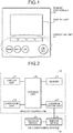
- FIG. 1 is a diagram illustrating an example of an external configuration of a remote controller according to a first embodiment of the present invention.
- a remote controller 10 illustrated in FIG. 1 includes a display unit 11 that displays an operation state typified by a set temperature and an operation mode, and an operation unit 12 that includes various types of operation buttons typified by an ON-OFF switch button and a menu button.
- An operation display unit may be provided instead of the display unit and the operation unit.
- the operation display unit may be implemented by a touch panel.
- FIG. 2 is a block diagram illustrating a configuration example of the remote controller according to the first embodiment of the present invention.
- the remote controller 10 illustrated in FIG. 2 includes the display unit 11, the operation unit 12, a control unit 20, a memory 21, and a communication unit 22.
- the display unit 11, the operation unit 12, the memory 21, and the communication unit 22 are connected to the control unit 20.
- the control unit 20 is implemented by a microcomputer and is a processor controlling an operation of the remote controller 10.
- the communication unit 22 is configured to perform bidirectional communication with an indoor device 52 of an air-conditioning system 50 in a wired or wireless manner.
- An outdoor device 51 and the indoor device 52 constitute a portion of the air-conditioning system 50 that is controlled by the remote controller 10.
- the memory 21 includes a non-volatile memory and stores therein a plurality of operation-state diagnosing tables used at least in maintenance and inspection of the air-conditioning system.
- the operation-state diagnosing tables are tables used for extracting necessary inspection items from the operation state of the air-conditioning system.
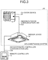
- FIG. 3 is a diagram illustrating a configuration example of the remote controller according to the first embodiment of the present invention, and the air-conditioning system to which the remote controller is connected.
- the air-conditioning system 50 to which the remote controller 10 is connected illustrated in FIG. 3 , includes the outdoor device 51, the indoor device 52, an indoor-outdoor communication line 53a connecting the outdoor device 51 and the indoor device 52, and an indoor-remote-controller communication line 53b connecting the indoor device 52 and the remote controller 10.
- the indoor-remote-controller communication line 53b connects the indoor device 52 and the remote controller 10 is illustrated here as an example, the present invention is not limited thereto.
- the remote controller 10 may be a wireless remote controller.
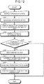
- FIG. 4 is a diagram illustrating an example of a flowchart of operation state diagnosing by the remote controller according to the first embodiment of the present invention.
- a maintenance-inspection person or a user inspects an operation state by operating the operation unit 12 of the remote controller 10, using an operation-state diagnosing table for a period until an indoor-device operation time and an outdoor-device operation time reach set times in the air-conditioning system 50 illustrated in FIG. 3 (S11).
- the remote controller 10 collects operation information including the operation times from the outdoor device 51 and the indoor device 52 via the indoor/remote-controller communication line 53b (S12).
- the indoor-device operation time and the outdoor-device operation time are assumed to be equal to each other in the first embodiment for the sake of convenience and there may be a case simply referred to as "operation time".
- FIG. 5 is a diagram illustrating an example of the items of the operation information collected in inspection by the remote controller according to the first embodiment of the present invention.
- FIG. 5 illustrates "outdoor discharge temperature”, “outdoor heat-exchange temperature”, “indoor intake temperature”, “indoor heat-exchange temperature”, “indoor-device operation time”, and “outdoor-device operation time” as the items, to which numbers (1) to (6) are given in that order, respectively.
- (7) indicates that another item may be included because the above described items are merely examples.
- outdoor discharge temperature is a temperature of air discharged from the outdoor device
- indoor intake temperature is a temperature of air taken in by the indoor device
- outdoor heat-exchange temperature is a temperature of a heat exchanger included in the outdoor device
- indoor heat-exchange temperature is a temperature of a heat exchanger included in the indoor device.
- the remote controller 10 extracts the operation time that is the indoor-device operation time and the outdoor-device operation time from the collected operation information (S13), and then determines an operation-state diagnosing table to be used based on the operation time that is the indoor-device operation time and the outdoor-device operation time. More specifically, the remote controller 10 determines whether the operation time is equal to or less than a first set time (S14), and uses an appropriate one of the operation-state diagnosing tables in accordance with a result of the above described determination.
- FIG. 6 is a diagram illustrating an example of a cooling operation-state diagnosing table stored in the memory of the remote controller according to the first embodiment of the present invention, in a case where the operation time is equal to or less than the first set time.
- FIG. 7 is a diagram illustrating an example of a heating operation-state diagnosing table stored in the memory of the remote controller according to the first embodiment of the present invention, in a case where the operation time is equal to or less than the first set time.
- FIG. 8 is a diagram illustrating an example of a cooling operation-state diagnosing table stored in the memory of the remote controller according to the first embodiment of the present invention, in a case where the operation time is above the first set time and is equal to or less than a second set time.
- the memory 21 of the remote controller 10 includes a plurality of operation-state diagnosing tables during cooling and a plurality of operation-state diagnosing tables during heating. That is, the memory 21 includes a plurality of operation-state diagnosing tables for every operation mode.
- the horizontal axis represents a difference obtained by subtracting the outdoor heat-exchange temperature from the outdoor discharge temperature
- the vertical axis represents a difference obtained by subtracting the indoor heat-exchange temperature from the indoor intake temperature
- the horizontal axis represents a difference obtained by subtracting the indoor heat-exchange temperature from the outdoor discharge temperature
- the vertical axis represents a difference obtained by subtracting the indoor intake temperature from the indoor heat-exchange temperature.
- an area of "normal” indicates that the operation of the air-conditioning system 50 is normal
- an area of "filter inspection” indicates a state where a filter included in the air-conditioning system 50 needs to be inspected
- areas of "inspection A", "inspection B", and “inspection C” indicate states where some predetermined inspection needs to be performed for the air-conditioning system 50.
- the difference obtained by subtracting the outdoor heat-exchange temperature from the outdoor discharge temperature is 20 and the difference obtained by subtracting the indoor heat-exchange temperature from the indoor intake temperature is 15, for example, it is determined that the air-conditioning system 50 is operating normally.
- operation state diagnosing is performed using a first operation-state diagnosing table (S15). That is, the operation state diagnosing is performed using the cooling operation-state diagnosing table illustrated in FIG. 6 for the cooling operation and the heating operation-state diagnosing table illustrated in FIG. 7 for the heating operation.
- the operation state diagnosing is performed using a second operation-state diagnosing table (S17). That is, the operation state diagnosing is performed using the cooling operation-state diagnosing table illustrated in FIG. 8 for the cooling operation and the heating operation-state diagnosing table illustrated in FIG. 9 for the heating operation.
- the second operation-state diagnosing table is a table used when the operation time is above the first set time and is equal to or less than the second set time.
- FIG. 10 is a diagram illustrating an example of a screen that displays a result of the operation state diagnosing in a normal operation in a case where the operation time is equal to or less than the first set time. In FIG. 10 , it is displayed that the air-conditioning system 50 is operating normally.
- FIG. 11 is a diagram illustrating an example of the screen that displays a result of the operation state diagnosing when an abnormality occurs in a case where the operation time is equal to or less than the first set time. In FIG. 11 , it is displayed on the display screen that detailed inspection is required.
- the detailed inspection described here is an inspection for a portion of the abnormality displayed by the operation state diagnosing, which is performed manually by the maintenance-inspection person or the user.
- An example of the detailed inspection is inspection in which the filter is detached from the air-conditioning system and is visually checked when the operation state diagnosing is a "filter inspection".
- the air-conditioning system includes a plurality of indoor devices and a maintenance data result in an indoor device with "refrigerant address 0", which is one of the indoor devices, is illustrated.
- the operation state diagnosing is performed one year after installation of the air-conditioning system 50, the operation state is diagnosed using the cooling operation-state diagnosing table illustrated in FIG. 6 or the heating operation-state diagnosing table illustrated in FIG. 7 , which is the first operation-state diagnosing table.
- the operation state diagnosing is performed three years after the installation of the air-conditioning system 50, the operation state is diagnosed using the cooling operation-state diagnosing table illustrated in FIG. 8 or the heating operation-state diagnosing table illustrated in FIG. 9 , which is the second operation-state diagnosing table.
- the present invention is not limited thereto.
- the present invention may be configured in such a manner that the set times are more finely divided to use three or more kinds of operation-state diagnosing tables as appropriate in each operation mode.
- a plurality of operation-state diagnosing tables are stored in the memory of the remote controller to be used as appropriate in accordance with the operation mode and the operation time of the air-conditioning system. Then, it is determined whether the current operation times of the indoor device and the outdoor device are equal to or less than set operation-time threshold values, respectively, and the operation-state diagnosing tables stored in the memory of the remote controller can automatically be switched based on the result of this determination.
- This configuration enables the operation state diagnosing to be conducted with a high degree of accuracy even after a long-term use.
- the operation-state diagnosing tables described in the first embodiment are created from test data, without considering an installation environment and an operation situation, such as an installation condition or a temperature condition. Therefore, in a case where the installation environment and the operation situation are different from those assumed at the time of acquisition of the test data, for example, in a case where the air-conditioning system is installed in a server room in which cooling is used throughout the year even in winter, it is not appropriate to use the operation-state diagnosing tables described in the first embodiment because the installation environment and the operation situation may be deviated from those assumed at the time of acquisition of the test data.
- FIG. 12 is a diagram illustrating an example of a flowchart of operation state diagnosing by a remote controller according to the second embodiment.
- the remote controller 10 inspects an operation state by an operation of the remote controller 10, as in the first embodiment (S21).
- the remote controller 10 diagnoses the operation state from operation information collected in association with the inspection of the operation state (S22) and displays a result of the operation state diagnosing on the display unit 11 (S23).
- the remote controller 10 corrects the operation-state diagnosing table based on the result at S24 input at S26 (S27), and performs the operation state diagnosing again as in the same manner as that at S22 (S28).
- the remote controller 10 displays the corrected result on the display unit 11 (S29).
- the diagnosing result is "normal” at S22 and the result is "normal” in the detailed inspection at S24 with no abnormality found, or a case where the diagnosis result is "filer inspection" at S22 and the detailed inspection at S24 shows that the filter is actually clogged, it can be said that the result at S22 and the result at S24 match each other.
- the diagnosis result is "normal” at S22 while the detailed inspection at S24 shows that the filter is actually clogged, or a case where the diagnosis result is "filter inspection” at S22 while the inspection result is "normal” in the detailed inspection at S24 with no abnormality found, the result at S22 and the result at S24 do not match each other.
- FIG. 13 is a diagram illustrating an example of an operation-state diagnosing table on which a result of the operation state diagnosing by the remote controller at S22 is plotted.
- FIG. 13 it is displayed that the result of the operation state diagnosing is out of a normal range and inspection B needs to be performed.
- the detailed inspection at S24 shows that inspection B is not necessary and the operation state is actually normal. Therefore, the remote controller 10 performs correction of the operation-state diagnosing table.
- FIG. 14 is a diagram illustrating an example of the operation-state diagnosing table corrected at S27.
- the result of the operation state diagnosing falls within the normal range due to the correction of the operation-state diagnosing table.
- the operation-state diagnosing tables stored in the memory of the remote controller can be corrected according to the installation environment and the operation situation.
- 10 remote controller 11 display unit, 12 operation unit, 20 control unit, 21 memory, 22 communication unit, 50 air-conditioning system, 51 outdoor device, 52 indoor device, 53a indoor/outdoor communication line, 53b indoor/remote-controller communication line.
Landscapes
- Engineering & Computer Science (AREA)
- Chemical & Material Sciences (AREA)
- Combustion & Propulsion (AREA)
- Mechanical Engineering (AREA)
- General Engineering & Computer Science (AREA)
- Physics & Mathematics (AREA)
- Fuzzy Systems (AREA)
- Mathematical Physics (AREA)
- Signal Processing (AREA)
- Air Conditioning Control Device (AREA)
Applications Claiming Priority (1)
| Application Number | Priority Date | Filing Date | Title |
|---|---|---|---|
| PCT/JP2015/065132 WO2016189665A1 (ja) | 2015-05-26 | 2015-05-26 | 空気調和システムのリモートコントローラ |
Publications (3)
| Publication Number | Publication Date |
|---|---|
| EP3214384A1 EP3214384A1 (en) | 2017-09-06 |
| EP3214384A4 EP3214384A4 (en) | 2017-09-06 |
| EP3214384B1 true EP3214384B1 (en) | 2020-11-18 |
Family
ID=57393903
Family Applications (1)
| Application Number | Title | Priority Date | Filing Date |
|---|---|---|---|
| EP15864299.1A Active EP3214384B1 (en) | 2015-05-26 | 2015-05-26 | Remote controller for air conditioning system |
Country Status (5)
| Country | Link |
|---|---|
| US (1) | US10365002B2 (ja) |
| EP (1) | EP3214384B1 (ja) |
| JP (1) | JP6355837B2 (ja) |
| CN (1) | CN108307650B (ja) |
| WO (1) | WO2016189665A1 (ja) |
Families Citing this family (4)
| Publication number | Priority date | Publication date | Assignee | Title |
|---|---|---|---|---|
| US11366461B2 (en) | 2015-08-14 | 2022-06-21 | Emerson Electric Co. | Remotely testing whether a climate control system controller is correctly installed |
| US10401830B2 (en) * | 2015-08-14 | 2019-09-03 | Emerson Electric Co. | Remotely testing whether a climate control system controller is correctly installed |
| EP3587946B1 (en) * | 2017-02-27 | 2021-09-01 | Mitsubishi Electric Corporation | Air conditioner |
| CN115406053A (zh) * | 2022-09-02 | 2022-11-29 | 珠海格力电器股份有限公司 | 空调器内外机通信方法、装置、空调器及存储介质 |
Family Cites Families (13)
| Publication number | Priority date | Publication date | Assignee | Title |
|---|---|---|---|---|
| JPH0776724B2 (ja) * | 1988-02-18 | 1995-08-16 | 富士重工業株式会社 | 車輌診断装置 |
| JPH04347444A (ja) * | 1991-05-23 | 1992-12-02 | Toshiba Corp | 空気調和機の室外ユニット情報表示システム |
| JP2000065415A (ja) * | 1998-08-19 | 2000-03-03 | Sanyo Electric Co Ltd | 空気調和機 |
| JP2003172567A (ja) | 2001-04-24 | 2003-06-20 | Fuji Electric Co Ltd | 故障診断方法、故障診断装置、店舗内機器管理システム、及び記録媒体 |
| JP4018374B2 (ja) * | 2001-11-21 | 2007-12-05 | 株式会社山武 | 空気調和機の異常検出装置、異常検出方法及びプログラム |
| JP2003316423A (ja) * | 2002-04-25 | 2003-11-07 | Daikin Ind Ltd | 設備機器診断装置及び設備機器診断システム |
| JP2008057921A (ja) | 2006-09-01 | 2008-03-13 | Sanyo Electric Co Ltd | 冷凍装置 |
| CN101278156B (zh) * | 2006-09-20 | 2011-04-20 | 三菱电机株式会社 | 空气调节系统 |
| JP5289109B2 (ja) | 2009-03-09 | 2013-09-11 | 三菱電機株式会社 | 空気調和装置 |
| AU2012200300B2 (en) | 2011-01-20 | 2015-08-20 | Fujitsu General Limited | Air conditioner |
| JP2013174385A (ja) * | 2012-02-24 | 2013-09-05 | Mitsubishi Electric Corp | 空気調和機システムおよびリモコン |
| JP5425282B1 (ja) | 2012-08-31 | 2014-02-26 | 三菱電機株式会社 | 遠隔制御システム、システムコントローラ及びプログラム |
| CN104566838B (zh) * | 2015-02-02 | 2017-11-14 | 珠海格力电器股份有限公司 | 空调器的故障检测方法和装置 |
-
2015
- 2015-05-26 WO PCT/JP2015/065132 patent/WO2016189665A1/ja active Application Filing
- 2015-05-26 EP EP15864299.1A patent/EP3214384B1/en active Active
- 2015-05-26 CN CN201580079038.5A patent/CN108307650B/zh active Active
- 2015-05-26 US US15/554,787 patent/US10365002B2/en active Active
- 2015-05-26 JP JP2017520133A patent/JP6355837B2/ja active Active
Non-Patent Citations (1)
| Title |
|---|
| None * |
Also Published As
| Publication number | Publication date |
|---|---|
| US10365002B2 (en) | 2019-07-30 |
| US20180038608A1 (en) | 2018-02-08 |
| CN108307650A (zh) | 2018-07-20 |
| JP6355837B2 (ja) | 2018-07-11 |
| EP3214384A1 (en) | 2017-09-06 |
| WO2016189665A1 (ja) | 2016-12-01 |
| JPWO2016189665A1 (ja) | 2017-08-10 |
| CN108307650B (zh) | 2020-09-18 |
| EP3214384A4 (en) | 2017-09-06 |
Similar Documents
| Publication | Publication Date | Title |
|---|---|---|
| US20170010014A1 (en) | Air conditioner test operation application, and air conditioner test operation system | |
| US7735328B2 (en) | Apparatus and method for monitoring state information in trial run mode of multi-airconditioner | |
| US9535408B2 (en) | Control system for a room air conditioner and/or heat pump | |
| US20200386430A1 (en) | Method and system for proactively and remotely diagnosing an hvac system | |
| EP3214384B1 (en) | Remote controller for air conditioning system | |
| AU2020222538B2 (en) | Device Management System | |
| EP2950010B1 (en) | Air conditioner | |
| ES2918206T3 (es) | Sistema de diagnóstico de averías | |
| US20170082309A1 (en) | Air-conditioning system | |
| EP3112766B1 (en) | Controller of heat source equipment | |
| JP2019060539A (ja) | 空気調和装置 | |
| US11913659B2 (en) | Systems and methods for monitoring operation of an HVAC system | |
| US8001230B2 (en) | Group management apparatus and group management system | |
| EP3007018B1 (en) | Controller for an air conditioning apparatus | |
| EP3232132B1 (en) | Air conditioning system | |
| KR20170082765A (ko) | 공기조화기의 제어장치 | |
| CN113383323B (zh) | 管理装置或设备信息发送装置 | |
| CN109764500B (zh) | 用于解决机组运行模式冲突的控制方法、装置及机组 | |
| WO2022185356A1 (ja) | 空気調和データ処理装置および空気調和装置管理システム |
Legal Events
| Date | Code | Title | Description |
|---|---|---|---|
| STAA | Information on the status of an ep patent application or granted ep patent |
Free format text: STATUS: UNKNOWN |
|
| STAA | Information on the status of an ep patent application or granted ep patent |
Free format text: STATUS: THE INTERNATIONAL PUBLICATION HAS BEEN MADE |
|
| PUAI | Public reference made under article 153(3) epc to a published international application that has entered the european phase |
Free format text: ORIGINAL CODE: 0009012 |
|
| STAA | Information on the status of an ep patent application or granted ep patent |
Free format text: STATUS: REQUEST FOR EXAMINATION WAS MADE |
|
| 17P | Request for examination filed |
Effective date: 20160606 |
|
| A4 | Supplementary search report drawn up and despatched |
Effective date: 20170208 |
|
| AK | Designated contracting states |
Kind code of ref document: A1 Designated state(s): AL AT BE BG CH CY CZ DE DK EE ES FI FR GB GR HR HU IE IS IT LI LT LU LV MC MK MT NL NO PL PT RO RS SE SI SK SM TR |
|
| AX | Request for extension of the european patent |
Extension state: BA ME |
|
| DAV | Request for validation of the european patent (deleted) | ||
| DAX | Request for extension of the european patent (deleted) | ||
| REG | Reference to a national code |
Ref country code: DE Ref legal event code: R079 Ref document number: 602015062323 Country of ref document: DE Free format text: PREVIOUS MAIN CLASS: F24F0011020000 Ipc: F24F0011000000 |
|
| GRAP | Despatch of communication of intention to grant a patent |
Free format text: ORIGINAL CODE: EPIDOSNIGR1 |
|
| STAA | Information on the status of an ep patent application or granted ep patent |
Free format text: STATUS: GRANT OF PATENT IS INTENDED |
|
| RIC1 | Information provided on ipc code assigned before grant |
Ipc: F24F 11/39 20180101ALN20200508BHEP Ipc: F24F 11/00 20180101AFI20200508BHEP Ipc: F24F 11/64 20180101ALN20200508BHEP Ipc: F24F 11/56 20180101ALN20200508BHEP |
|
| INTG | Intention to grant announced |
Effective date: 20200527 |
|
| GRAS | Grant fee paid |
Free format text: ORIGINAL CODE: EPIDOSNIGR3 |
|
| GRAA | (expected) grant |
Free format text: ORIGINAL CODE: 0009210 |
|
| STAA | Information on the status of an ep patent application or granted ep patent |
Free format text: STATUS: THE PATENT HAS BEEN GRANTED |
|
| AK | Designated contracting states |
Kind code of ref document: B1 Designated state(s): AL AT BE BG CH CY CZ DE DK EE ES FI FR GB GR HR HU IE IS IT LI LT LU LV MC MK MT NL NO PL PT RO RS SE SI SK SM TR |
|
| REG | Reference to a national code |
Ref country code: GB Ref legal event code: FG4D |
|
| REG | Reference to a national code |
Ref country code: CH Ref legal event code: EP |
|
| REG | Reference to a national code |
Ref country code: IE Ref legal event code: FG4D |
|
| REG | Reference to a national code |
Ref country code: DE Ref legal event code: R096 Ref document number: 602015062323 Country of ref document: DE |
|
| REG | Reference to a national code |
Ref country code: AT Ref legal event code: REF Ref document number: 1336196 Country of ref document: AT Kind code of ref document: T Effective date: 20201215 |
|
| REG | Reference to a national code |
Ref country code: AT Ref legal event code: MK05 Ref document number: 1336196 Country of ref document: AT Kind code of ref document: T Effective date: 20201118 |
|
| REG | Reference to a national code |
Ref country code: NL Ref legal event code: MP Effective date: 20201118 |
|
| PG25 | Lapsed in a contracting state [announced via postgrant information from national office to epo] |
Ref country code: RS Free format text: LAPSE BECAUSE OF FAILURE TO SUBMIT A TRANSLATION OF THE DESCRIPTION OR TO PAY THE FEE WITHIN THE PRESCRIBED TIME-LIMIT Effective date: 20201118 Ref country code: PT Free format text: LAPSE BECAUSE OF FAILURE TO SUBMIT A TRANSLATION OF THE DESCRIPTION OR TO PAY THE FEE WITHIN THE PRESCRIBED TIME-LIMIT Effective date: 20210318 Ref country code: FI Free format text: LAPSE BECAUSE OF FAILURE TO SUBMIT A TRANSLATION OF THE DESCRIPTION OR TO PAY THE FEE WITHIN THE PRESCRIBED TIME-LIMIT Effective date: 20201118 Ref country code: NO Free format text: LAPSE BECAUSE OF FAILURE TO SUBMIT A TRANSLATION OF THE DESCRIPTION OR TO PAY THE FEE WITHIN THE PRESCRIBED TIME-LIMIT Effective date: 20210218 Ref country code: GR Free format text: LAPSE BECAUSE OF FAILURE TO SUBMIT A TRANSLATION OF THE DESCRIPTION OR TO PAY THE FEE WITHIN THE PRESCRIBED TIME-LIMIT Effective date: 20210219 |
|
| PG25 | Lapsed in a contracting state [announced via postgrant information from national office to epo] |
Ref country code: BG Free format text: LAPSE BECAUSE OF FAILURE TO SUBMIT A TRANSLATION OF THE DESCRIPTION OR TO PAY THE FEE WITHIN THE PRESCRIBED TIME-LIMIT Effective date: 20210218 Ref country code: IS Free format text: LAPSE BECAUSE OF FAILURE TO SUBMIT A TRANSLATION OF THE DESCRIPTION OR TO PAY THE FEE WITHIN THE PRESCRIBED TIME-LIMIT Effective date: 20210318 Ref country code: SE Free format text: LAPSE BECAUSE OF FAILURE TO SUBMIT A TRANSLATION OF THE DESCRIPTION OR TO PAY THE FEE WITHIN THE PRESCRIBED TIME-LIMIT Effective date: 20201118 Ref country code: PL Free format text: LAPSE BECAUSE OF FAILURE TO SUBMIT A TRANSLATION OF THE DESCRIPTION OR TO PAY THE FEE WITHIN THE PRESCRIBED TIME-LIMIT Effective date: 20201118 Ref country code: LV Free format text: LAPSE BECAUSE OF FAILURE TO SUBMIT A TRANSLATION OF THE DESCRIPTION OR TO PAY THE FEE WITHIN THE PRESCRIBED TIME-LIMIT Effective date: 20201118 Ref country code: AT Free format text: LAPSE BECAUSE OF FAILURE TO SUBMIT A TRANSLATION OF THE DESCRIPTION OR TO PAY THE FEE WITHIN THE PRESCRIBED TIME-LIMIT Effective date: 20201118 |
|
| REG | Reference to a national code |
Ref country code: LT Ref legal event code: MG9D |
|
| PG25 | Lapsed in a contracting state [announced via postgrant information from national office to epo] |
Ref country code: HR Free format text: LAPSE BECAUSE OF FAILURE TO SUBMIT A TRANSLATION OF THE DESCRIPTION OR TO PAY THE FEE WITHIN THE PRESCRIBED TIME-LIMIT Effective date: 20201118 |
|
| PG25 | Lapsed in a contracting state [announced via postgrant information from national office to epo] |
Ref country code: RO Free format text: LAPSE BECAUSE OF FAILURE TO SUBMIT A TRANSLATION OF THE DESCRIPTION OR TO PAY THE FEE WITHIN THE PRESCRIBED TIME-LIMIT Effective date: 20201118 Ref country code: SK Free format text: LAPSE BECAUSE OF FAILURE TO SUBMIT A TRANSLATION OF THE DESCRIPTION OR TO PAY THE FEE WITHIN THE PRESCRIBED TIME-LIMIT Effective date: 20201118 Ref country code: SM Free format text: LAPSE BECAUSE OF FAILURE TO SUBMIT A TRANSLATION OF THE DESCRIPTION OR TO PAY THE FEE WITHIN THE PRESCRIBED TIME-LIMIT Effective date: 20201118 Ref country code: LT Free format text: LAPSE BECAUSE OF FAILURE TO SUBMIT A TRANSLATION OF THE DESCRIPTION OR TO PAY THE FEE WITHIN THE PRESCRIBED TIME-LIMIT Effective date: 20201118 Ref country code: CZ Free format text: LAPSE BECAUSE OF FAILURE TO SUBMIT A TRANSLATION OF THE DESCRIPTION OR TO PAY THE FEE WITHIN THE PRESCRIBED TIME-LIMIT Effective date: 20201118 Ref country code: EE Free format text: LAPSE BECAUSE OF FAILURE TO SUBMIT A TRANSLATION OF THE DESCRIPTION OR TO PAY THE FEE WITHIN THE PRESCRIBED TIME-LIMIT Effective date: 20201118 |
|
| REG | Reference to a national code |
Ref country code: DE Ref legal event code: R097 Ref document number: 602015062323 Country of ref document: DE |
|
| PG25 | Lapsed in a contracting state [announced via postgrant information from national office to epo] |
Ref country code: DK Free format text: LAPSE BECAUSE OF FAILURE TO SUBMIT A TRANSLATION OF THE DESCRIPTION OR TO PAY THE FEE WITHIN THE PRESCRIBED TIME-LIMIT Effective date: 20201118 |
|
| PLBE | No opposition filed within time limit |
Free format text: ORIGINAL CODE: 0009261 |
|
| STAA | Information on the status of an ep patent application or granted ep patent |
Free format text: STATUS: NO OPPOSITION FILED WITHIN TIME LIMIT |
|
| 26N | No opposition filed |
Effective date: 20210819 |
|
| PG25 | Lapsed in a contracting state [announced via postgrant information from national office to epo] |
Ref country code: NL Free format text: LAPSE BECAUSE OF FAILURE TO SUBMIT A TRANSLATION OF THE DESCRIPTION OR TO PAY THE FEE WITHIN THE PRESCRIBED TIME-LIMIT Effective date: 20201118 Ref country code: IT Free format text: LAPSE BECAUSE OF FAILURE TO SUBMIT A TRANSLATION OF THE DESCRIPTION OR TO PAY THE FEE WITHIN THE PRESCRIBED TIME-LIMIT Effective date: 20201118 Ref country code: AL Free format text: LAPSE BECAUSE OF FAILURE TO SUBMIT A TRANSLATION OF THE DESCRIPTION OR TO PAY THE FEE WITHIN THE PRESCRIBED TIME-LIMIT Effective date: 20201118 |
|
| PG25 | Lapsed in a contracting state [announced via postgrant information from national office to epo] |
Ref country code: SI Free format text: LAPSE BECAUSE OF FAILURE TO SUBMIT A TRANSLATION OF THE DESCRIPTION OR TO PAY THE FEE WITHIN THE PRESCRIBED TIME-LIMIT Effective date: 20201118 |
|
| REG | Reference to a national code |
Ref country code: CH Ref legal event code: PL |
|
| PG25 | Lapsed in a contracting state [announced via postgrant information from national office to epo] |
Ref country code: MC Free format text: LAPSE BECAUSE OF FAILURE TO SUBMIT A TRANSLATION OF THE DESCRIPTION OR TO PAY THE FEE WITHIN THE PRESCRIBED TIME-LIMIT Effective date: 20201118 Ref country code: LI Free format text: LAPSE BECAUSE OF NON-PAYMENT OF DUE FEES Effective date: 20210531 Ref country code: LU Free format text: LAPSE BECAUSE OF NON-PAYMENT OF DUE FEES Effective date: 20210526 Ref country code: CH Free format text: LAPSE BECAUSE OF NON-PAYMENT OF DUE FEES Effective date: 20210531 Ref country code: ES Free format text: LAPSE BECAUSE OF FAILURE TO SUBMIT A TRANSLATION OF THE DESCRIPTION OR TO PAY THE FEE WITHIN THE PRESCRIBED TIME-LIMIT Effective date: 20201118 |
|
| REG | Reference to a national code |
Ref country code: BE Ref legal event code: MM Effective date: 20210531 |
|
| PG25 | Lapsed in a contracting state [announced via postgrant information from national office to epo] |
Ref country code: IE Free format text: LAPSE BECAUSE OF NON-PAYMENT OF DUE FEES Effective date: 20210526 |
|
| PG25 | Lapsed in a contracting state [announced via postgrant information from national office to epo] |
Ref country code: IS Free format text: LAPSE BECAUSE OF FAILURE TO SUBMIT A TRANSLATION OF THE DESCRIPTION OR TO PAY THE FEE WITHIN THE PRESCRIBED TIME-LIMIT Effective date: 20210318 Ref country code: FR Free format text: LAPSE BECAUSE OF NON-PAYMENT OF DUE FEES Effective date: 20210531 |
|
| PG25 | Lapsed in a contracting state [announced via postgrant information from national office to epo] |
Ref country code: BE Free format text: LAPSE BECAUSE OF NON-PAYMENT OF DUE FEES Effective date: 20210531 |
|
| PG25 | Lapsed in a contracting state [announced via postgrant information from national office to epo] |
Ref country code: HU Free format text: LAPSE BECAUSE OF FAILURE TO SUBMIT A TRANSLATION OF THE DESCRIPTION OR TO PAY THE FEE WITHIN THE PRESCRIBED TIME-LIMIT; INVALID AB INITIO Effective date: 20150526 |
|
| P01 | Opt-out of the competence of the unified patent court (upc) registered |
Effective date: 20230512 |
|
| PG25 | Lapsed in a contracting state [announced via postgrant information from national office to epo] |
Ref country code: CY Free format text: LAPSE BECAUSE OF FAILURE TO SUBMIT A TRANSLATION OF THE DESCRIPTION OR TO PAY THE FEE WITHIN THE PRESCRIBED TIME-LIMIT Effective date: 20201118 |
|
| PGFP | Annual fee paid to national office [announced via postgrant information from national office to epo] |
Ref country code: DE Payment date: 20230331 Year of fee payment: 9 |
|
| PGFP | Annual fee paid to national office [announced via postgrant information from national office to epo] |
Ref country code: GB Payment date: 20230406 Year of fee payment: 9 |
|
| PG25 | Lapsed in a contracting state [announced via postgrant information from national office to epo] |
Ref country code: MK Free format text: LAPSE BECAUSE OF FAILURE TO SUBMIT A TRANSLATION OF THE DESCRIPTION OR TO PAY THE FEE WITHIN THE PRESCRIBED TIME-LIMIT Effective date: 20201118 |