EP3210951A1 - Kupfer-keramik-verbund - Google Patents
Kupfer-keramik-verbund Download PDFInfo
- Publication number
- EP3210951A1 EP3210951A1 EP16157639.2A EP16157639A EP3210951A1 EP 3210951 A1 EP3210951 A1 EP 3210951A1 EP 16157639 A EP16157639 A EP 16157639A EP 3210951 A1 EP3210951 A1 EP 3210951A1
- Authority
- EP
- European Patent Office
- Prior art keywords
- copper
- ceramic substrate
- ceramic
- range
- grain
- Prior art date
- Legal status (The legal status is an assumption and is not a legal conclusion. Google has not performed a legal analysis and makes no representation as to the accuracy of the status listed.)
- Granted
Links
Images

Classifications
-
- C—CHEMISTRY; METALLURGY
- C04—CEMENTS; CONCRETE; ARTIFICIAL STONE; CERAMICS; REFRACTORIES
- C04B—LIME, MAGNESIA; SLAG; CEMENTS; COMPOSITIONS THEREOF, e.g. MORTARS, CONCRETE OR LIKE BUILDING MATERIALS; ARTIFICIAL STONE; CERAMICS; REFRACTORIES; TREATMENT OF NATURAL STONE
- C04B41/00—After-treatment of mortars, concrete, artificial stone or ceramics; Treatment of natural stone
- C04B41/45—Coating or impregnating, e.g. injection in masonry, partial coating of green or fired ceramics, organic coating compositions for adhering together two concrete elements
- C04B41/50—Coating or impregnating, e.g. injection in masonry, partial coating of green or fired ceramics, organic coating compositions for adhering together two concrete elements with inorganic materials
- C04B41/51—Metallising, e.g. infiltration of sintered ceramic preforms with molten metal
- C04B41/5111—Ag, Au, Pd, Pt or Cu
-
- C—CHEMISTRY; METALLURGY
- C04—CEMENTS; CONCRETE; ARTIFICIAL STONE; CERAMICS; REFRACTORIES
- C04B—LIME, MAGNESIA; SLAG; CEMENTS; COMPOSITIONS THEREOF, e.g. MORTARS, CONCRETE OR LIKE BUILDING MATERIALS; ARTIFICIAL STONE; CERAMICS; REFRACTORIES; TREATMENT OF NATURAL STONE
- C04B35/00—Shaped ceramic products characterised by their composition; Ceramics compositions; Processing powders of inorganic compounds preparatory to the manufacturing of ceramic products
- C04B35/01—Shaped ceramic products characterised by their composition; Ceramics compositions; Processing powders of inorganic compounds preparatory to the manufacturing of ceramic products based on oxide ceramics
- C04B35/10—Shaped ceramic products characterised by their composition; Ceramics compositions; Processing powders of inorganic compounds preparatory to the manufacturing of ceramic products based on oxide ceramics based on aluminium oxide
- C04B35/111—Fine ceramics
-
- C—CHEMISTRY; METALLURGY
- C04—CEMENTS; CONCRETE; ARTIFICIAL STONE; CERAMICS; REFRACTORIES
- C04B—LIME, MAGNESIA; SLAG; CEMENTS; COMPOSITIONS THEREOF, e.g. MORTARS, CONCRETE OR LIKE BUILDING MATERIALS; ARTIFICIAL STONE; CERAMICS; REFRACTORIES; TREATMENT OF NATURAL STONE
- C04B35/00—Shaped ceramic products characterised by their composition; Ceramics compositions; Processing powders of inorganic compounds preparatory to the manufacturing of ceramic products
- C04B35/01—Shaped ceramic products characterised by their composition; Ceramics compositions; Processing powders of inorganic compounds preparatory to the manufacturing of ceramic products based on oxide ceramics
- C04B35/10—Shaped ceramic products characterised by their composition; Ceramics compositions; Processing powders of inorganic compounds preparatory to the manufacturing of ceramic products based on oxide ceramics based on aluminium oxide
-
- C—CHEMISTRY; METALLURGY
- C04—CEMENTS; CONCRETE; ARTIFICIAL STONE; CERAMICS; REFRACTORIES
- C04B—LIME, MAGNESIA; SLAG; CEMENTS; COMPOSITIONS THEREOF, e.g. MORTARS, CONCRETE OR LIKE BUILDING MATERIALS; ARTIFICIAL STONE; CERAMICS; REFRACTORIES; TREATMENT OF NATURAL STONE
- C04B37/00—Joining burned ceramic articles with other burned ceramic articles or other articles by heating
- C04B37/02—Joining burned ceramic articles with other burned ceramic articles or other articles by heating with metallic articles
- C04B37/021—Joining burned ceramic articles with other burned ceramic articles or other articles by heating with metallic articles in a direct manner, e.g. direct copper bonding [DCB]
-
- C—CHEMISTRY; METALLURGY
- C04—CEMENTS; CONCRETE; ARTIFICIAL STONE; CERAMICS; REFRACTORIES
- C04B—LIME, MAGNESIA; SLAG; CEMENTS; COMPOSITIONS THEREOF, e.g. MORTARS, CONCRETE OR LIKE BUILDING MATERIALS; ARTIFICIAL STONE; CERAMICS; REFRACTORIES; TREATMENT OF NATURAL STONE
- C04B41/00—After-treatment of mortars, concrete, artificial stone or ceramics; Treatment of natural stone
- C04B41/80—After-treatment of mortars, concrete, artificial stone or ceramics; Treatment of natural stone of only ceramics
- C04B41/81—Coating or impregnation
- C04B41/85—Coating or impregnation with inorganic materials
- C04B41/88—Metals
-
- H—ELECTRICITY
- H10—SEMICONDUCTOR DEVICES; ELECTRIC SOLID-STATE DEVICES NOT OTHERWISE PROVIDED FOR
- H10W—GENERIC PACKAGES, INTERCONNECTIONS, CONNECTORS OR OTHER CONSTRUCTIONAL DETAILS OF DEVICES COVERED BY CLASS H10
- H10W40/00—Arrangements for thermal protection or thermal control
- H10W40/20—Arrangements for cooling
- H10W40/25—Arrangements for cooling characterised by their materials
- H10W40/255—Arrangements for cooling characterised by their materials having a laminate or multilayered structure, e.g. direct bond copper [DBC] ceramic substrates
-
- C—CHEMISTRY; METALLURGY
- C04—CEMENTS; CONCRETE; ARTIFICIAL STONE; CERAMICS; REFRACTORIES
- C04B—LIME, MAGNESIA; SLAG; CEMENTS; COMPOSITIONS THEREOF, e.g. MORTARS, CONCRETE OR LIKE BUILDING MATERIALS; ARTIFICIAL STONE; CERAMICS; REFRACTORIES; TREATMENT OF NATURAL STONE
- C04B2235/00—Aspects relating to ceramic starting mixtures or sintered ceramic products
- C04B2235/02—Composition of constituents of the starting material or of secondary phases of the final product
- C04B2235/30—Constituents and secondary phases not being of a fibrous nature
- C04B2235/32—Metal oxides, mixed metal oxides, or oxide-forming salts thereof, e.g. carbonates, nitrates, (oxy)hydroxides, chlorides
- C04B2235/3217—Aluminum oxide or oxide forming salts thereof, e.g. bauxite, alpha-alumina
-
- C—CHEMISTRY; METALLURGY
- C04—CEMENTS; CONCRETE; ARTIFICIAL STONE; CERAMICS; REFRACTORIES
- C04B—LIME, MAGNESIA; SLAG; CEMENTS; COMPOSITIONS THEREOF, e.g. MORTARS, CONCRETE OR LIKE BUILDING MATERIALS; ARTIFICIAL STONE; CERAMICS; REFRACTORIES; TREATMENT OF NATURAL STONE
- C04B2235/00—Aspects relating to ceramic starting mixtures or sintered ceramic products
- C04B2235/02—Composition of constituents of the starting material or of secondary phases of the final product
- C04B2235/50—Constituents or additives of the starting mixture chosen for their shape or used because of their shape or their physical appearance
- C04B2235/54—Particle size related information
- C04B2235/5418—Particle size related information expressed by the size of the particles or aggregates thereof
- C04B2235/5436—Particle size related information expressed by the size of the particles or aggregates thereof micrometer sized, i.e. from 1 to 100 micron
-
- C—CHEMISTRY; METALLURGY
- C04—CEMENTS; CONCRETE; ARTIFICIAL STONE; CERAMICS; REFRACTORIES
- C04B—LIME, MAGNESIA; SLAG; CEMENTS; COMPOSITIONS THEREOF, e.g. MORTARS, CONCRETE OR LIKE BUILDING MATERIALS; ARTIFICIAL STONE; CERAMICS; REFRACTORIES; TREATMENT OF NATURAL STONE
- C04B2235/00—Aspects relating to ceramic starting mixtures or sintered ceramic products
- C04B2235/02—Composition of constituents of the starting material or of secondary phases of the final product
- C04B2235/50—Constituents or additives of the starting mixture chosen for their shape or used because of their shape or their physical appearance
- C04B2235/54—Particle size related information
- C04B2235/5418—Particle size related information expressed by the size of the particles or aggregates thereof
- C04B2235/5445—Particle size related information expressed by the size of the particles or aggregates thereof submicron sized, i.e. from 0,1 to 1 micron
-
- C—CHEMISTRY; METALLURGY
- C04—CEMENTS; CONCRETE; ARTIFICIAL STONE; CERAMICS; REFRACTORIES
- C04B—LIME, MAGNESIA; SLAG; CEMENTS; COMPOSITIONS THEREOF, e.g. MORTARS, CONCRETE OR LIKE BUILDING MATERIALS; ARTIFICIAL STONE; CERAMICS; REFRACTORIES; TREATMENT OF NATURAL STONE
- C04B2235/00—Aspects relating to ceramic starting mixtures or sintered ceramic products
- C04B2235/70—Aspects relating to sintered or melt-casted ceramic products
- C04B2235/74—Physical characteristics
- C04B2235/78—Grain sizes and shapes, product microstructures, e.g. acicular grains, equiaxed grains, platelet-structures
- C04B2235/782—Grain size distributions
-
- C—CHEMISTRY; METALLURGY
- C04—CEMENTS; CONCRETE; ARTIFICIAL STONE; CERAMICS; REFRACTORIES
- C04B—LIME, MAGNESIA; SLAG; CEMENTS; COMPOSITIONS THEREOF, e.g. MORTARS, CONCRETE OR LIKE BUILDING MATERIALS; ARTIFICIAL STONE; CERAMICS; REFRACTORIES; TREATMENT OF NATURAL STONE
- C04B2235/00—Aspects relating to ceramic starting mixtures or sintered ceramic products
- C04B2235/70—Aspects relating to sintered or melt-casted ceramic products
- C04B2235/74—Physical characteristics
- C04B2235/78—Grain sizes and shapes, product microstructures, e.g. acicular grains, equiaxed grains, platelet-structures
- C04B2235/786—Micrometer sized grains, i.e. from 1 to 100 micron
-
- C—CHEMISTRY; METALLURGY
- C04—CEMENTS; CONCRETE; ARTIFICIAL STONE; CERAMICS; REFRACTORIES
- C04B—LIME, MAGNESIA; SLAG; CEMENTS; COMPOSITIONS THEREOF, e.g. MORTARS, CONCRETE OR LIKE BUILDING MATERIALS; ARTIFICIAL STONE; CERAMICS; REFRACTORIES; TREATMENT OF NATURAL STONE
- C04B2235/00—Aspects relating to ceramic starting mixtures or sintered ceramic products
- C04B2235/70—Aspects relating to sintered or melt-casted ceramic products
- C04B2235/74—Physical characteristics
- C04B2235/78—Grain sizes and shapes, product microstructures, e.g. acicular grains, equiaxed grains, platelet-structures
- C04B2235/788—Aspect ratio of the grains
-
- C—CHEMISTRY; METALLURGY
- C04—CEMENTS; CONCRETE; ARTIFICIAL STONE; CERAMICS; REFRACTORIES
- C04B—LIME, MAGNESIA; SLAG; CEMENTS; COMPOSITIONS THEREOF, e.g. MORTARS, CONCRETE OR LIKE BUILDING MATERIALS; ARTIFICIAL STONE; CERAMICS; REFRACTORIES; TREATMENT OF NATURAL STONE
- C04B2235/00—Aspects relating to ceramic starting mixtures or sintered ceramic products
- C04B2235/70—Aspects relating to sintered or melt-casted ceramic products
- C04B2235/96—Properties of ceramic products, e.g. mechanical properties such as strength, toughness, wear resistance
- C04B2235/9607—Thermal properties, e.g. thermal expansion coefficient
-
- C—CHEMISTRY; METALLURGY
- C04—CEMENTS; CONCRETE; ARTIFICIAL STONE; CERAMICS; REFRACTORIES
- C04B—LIME, MAGNESIA; SLAG; CEMENTS; COMPOSITIONS THEREOF, e.g. MORTARS, CONCRETE OR LIKE BUILDING MATERIALS; ARTIFICIAL STONE; CERAMICS; REFRACTORIES; TREATMENT OF NATURAL STONE
- C04B2237/00—Aspects relating to ceramic laminates or to joining of ceramic articles with other articles by heating
- C04B2237/30—Composition of layers of ceramic laminates or of ceramic or metallic articles to be joined by heating, e.g. Si substrates
- C04B2237/32—Ceramic
-
- C—CHEMISTRY; METALLURGY
- C04—CEMENTS; CONCRETE; ARTIFICIAL STONE; CERAMICS; REFRACTORIES
- C04B—LIME, MAGNESIA; SLAG; CEMENTS; COMPOSITIONS THEREOF, e.g. MORTARS, CONCRETE OR LIKE BUILDING MATERIALS; ARTIFICIAL STONE; CERAMICS; REFRACTORIES; TREATMENT OF NATURAL STONE
- C04B2237/00—Aspects relating to ceramic laminates or to joining of ceramic articles with other articles by heating
- C04B2237/30—Composition of layers of ceramic laminates or of ceramic or metallic articles to be joined by heating, e.g. Si substrates
- C04B2237/32—Ceramic
- C04B2237/34—Oxidic
-
- C—CHEMISTRY; METALLURGY
- C04—CEMENTS; CONCRETE; ARTIFICIAL STONE; CERAMICS; REFRACTORIES
- C04B—LIME, MAGNESIA; SLAG; CEMENTS; COMPOSITIONS THEREOF, e.g. MORTARS, CONCRETE OR LIKE BUILDING MATERIALS; ARTIFICIAL STONE; CERAMICS; REFRACTORIES; TREATMENT OF NATURAL STONE
- C04B2237/00—Aspects relating to ceramic laminates or to joining of ceramic articles with other articles by heating
- C04B2237/30—Composition of layers of ceramic laminates or of ceramic or metallic articles to be joined by heating, e.g. Si substrates
- C04B2237/32—Ceramic
- C04B2237/34—Oxidic
- C04B2237/343—Alumina or aluminates
-
- C—CHEMISTRY; METALLURGY
- C04—CEMENTS; CONCRETE; ARTIFICIAL STONE; CERAMICS; REFRACTORIES
- C04B—LIME, MAGNESIA; SLAG; CEMENTS; COMPOSITIONS THEREOF, e.g. MORTARS, CONCRETE OR LIKE BUILDING MATERIALS; ARTIFICIAL STONE; CERAMICS; REFRACTORIES; TREATMENT OF NATURAL STONE
- C04B2237/00—Aspects relating to ceramic laminates or to joining of ceramic articles with other articles by heating
- C04B2237/30—Composition of layers of ceramic laminates or of ceramic or metallic articles to be joined by heating, e.g. Si substrates
- C04B2237/32—Ceramic
- C04B2237/36—Non-oxidic
-
- C—CHEMISTRY; METALLURGY
- C04—CEMENTS; CONCRETE; ARTIFICIAL STONE; CERAMICS; REFRACTORIES
- C04B—LIME, MAGNESIA; SLAG; CEMENTS; COMPOSITIONS THEREOF, e.g. MORTARS, CONCRETE OR LIKE BUILDING MATERIALS; ARTIFICIAL STONE; CERAMICS; REFRACTORIES; TREATMENT OF NATURAL STONE
- C04B2237/00—Aspects relating to ceramic laminates or to joining of ceramic articles with other articles by heating
- C04B2237/30—Composition of layers of ceramic laminates or of ceramic or metallic articles to be joined by heating, e.g. Si substrates
- C04B2237/32—Ceramic
- C04B2237/36—Non-oxidic
- C04B2237/365—Silicon carbide
-
- C—CHEMISTRY; METALLURGY
- C04—CEMENTS; CONCRETE; ARTIFICIAL STONE; CERAMICS; REFRACTORIES
- C04B—LIME, MAGNESIA; SLAG; CEMENTS; COMPOSITIONS THEREOF, e.g. MORTARS, CONCRETE OR LIKE BUILDING MATERIALS; ARTIFICIAL STONE; CERAMICS; REFRACTORIES; TREATMENT OF NATURAL STONE
- C04B2237/00—Aspects relating to ceramic laminates or to joining of ceramic articles with other articles by heating
- C04B2237/30—Composition of layers of ceramic laminates or of ceramic or metallic articles to be joined by heating, e.g. Si substrates
- C04B2237/32—Ceramic
- C04B2237/36—Non-oxidic
- C04B2237/366—Aluminium nitride
-
- C—CHEMISTRY; METALLURGY
- C04—CEMENTS; CONCRETE; ARTIFICIAL STONE; CERAMICS; REFRACTORIES
- C04B—LIME, MAGNESIA; SLAG; CEMENTS; COMPOSITIONS THEREOF, e.g. MORTARS, CONCRETE OR LIKE BUILDING MATERIALS; ARTIFICIAL STONE; CERAMICS; REFRACTORIES; TREATMENT OF NATURAL STONE
- C04B2237/00—Aspects relating to ceramic laminates or to joining of ceramic articles with other articles by heating
- C04B2237/30—Composition of layers of ceramic laminates or of ceramic or metallic articles to be joined by heating, e.g. Si substrates
- C04B2237/32—Ceramic
- C04B2237/36—Non-oxidic
- C04B2237/368—Silicon nitride
-
- C—CHEMISTRY; METALLURGY
- C04—CEMENTS; CONCRETE; ARTIFICIAL STONE; CERAMICS; REFRACTORIES
- C04B—LIME, MAGNESIA; SLAG; CEMENTS; COMPOSITIONS THEREOF, e.g. MORTARS, CONCRETE OR LIKE BUILDING MATERIALS; ARTIFICIAL STONE; CERAMICS; REFRACTORIES; TREATMENT OF NATURAL STONE
- C04B2237/00—Aspects relating to ceramic laminates or to joining of ceramic articles with other articles by heating
- C04B2237/30—Composition of layers of ceramic laminates or of ceramic or metallic articles to be joined by heating, e.g. Si substrates
- C04B2237/40—Metallic
-
- C—CHEMISTRY; METALLURGY
- C04—CEMENTS; CONCRETE; ARTIFICIAL STONE; CERAMICS; REFRACTORIES
- C04B—LIME, MAGNESIA; SLAG; CEMENTS; COMPOSITIONS THEREOF, e.g. MORTARS, CONCRETE OR LIKE BUILDING MATERIALS; ARTIFICIAL STONE; CERAMICS; REFRACTORIES; TREATMENT OF NATURAL STONE
- C04B2237/00—Aspects relating to ceramic laminates or to joining of ceramic articles with other articles by heating
- C04B2237/30—Composition of layers of ceramic laminates or of ceramic or metallic articles to be joined by heating, e.g. Si substrates
- C04B2237/40—Metallic
- C04B2237/407—Copper
-
- C—CHEMISTRY; METALLURGY
- C04—CEMENTS; CONCRETE; ARTIFICIAL STONE; CERAMICS; REFRACTORIES
- C04B—LIME, MAGNESIA; SLAG; CEMENTS; COMPOSITIONS THEREOF, e.g. MORTARS, CONCRETE OR LIKE BUILDING MATERIALS; ARTIFICIAL STONE; CERAMICS; REFRACTORIES; TREATMENT OF NATURAL STONE
- C04B2237/00—Aspects relating to ceramic laminates or to joining of ceramic articles with other articles by heating
- C04B2237/50—Processing aspects relating to ceramic laminates or to the joining of ceramic articles with other articles by heating
- C04B2237/54—Oxidising the surface before joining
-
- C—CHEMISTRY; METALLURGY
- C04—CEMENTS; CONCRETE; ARTIFICIAL STONE; CERAMICS; REFRACTORIES
- C04B—LIME, MAGNESIA; SLAG; CEMENTS; COMPOSITIONS THEREOF, e.g. MORTARS, CONCRETE OR LIKE BUILDING MATERIALS; ARTIFICIAL STONE; CERAMICS; REFRACTORIES; TREATMENT OF NATURAL STONE
- C04B2237/00—Aspects relating to ceramic laminates or to joining of ceramic articles with other articles by heating
- C04B2237/50—Processing aspects relating to ceramic laminates or to the joining of ceramic articles with other articles by heating
- C04B2237/60—Forming at the joining interface or in the joining layer specific reaction phases or zones, e.g. diffusion of reactive species from the interlayer to the substrate or from a substrate to the joining interface, carbide forming at the joining interface
-
- H—ELECTRICITY
- H10—SEMICONDUCTOR DEVICES; ELECTRIC SOLID-STATE DEVICES NOT OTHERWISE PROVIDED FOR
- H10W—GENERIC PACKAGES, INTERCONNECTIONS, CONNECTORS OR OTHER CONSTRUCTIONAL DETAILS OF DEVICES COVERED BY CLASS H10
- H10W70/00—Package substrates; Interposers; Redistribution layers [RDL]
- H10W70/60—Insulating or insulated package substrates; Interposers; Redistribution layers
- H10W70/67—Insulating or insulated package substrates; Interposers; Redistribution layers characterised by their insulating layers or insulating parts
- H10W70/69—Insulating materials thereof
- H10W70/692—Ceramics or glasses
Definitions
- the present invention relates to a copper-ceramic composite and a module containing this composite, which can be used in power electronics components.
- Ceramic circuit carriers are due to their high thermal conductivity, high dimensional stability or mechanical strength and their high insulation resistance, especially in the field of high-performance electronics of interest.
- DCB Direct Copper Bonding
- AMB Active Metal Brazing
- the composite material obtained after metallization of the ceramic substrate is also referred to as metal-ceramic substrate or metal-ceramic composite.
- metal-ceramic substrate or metal-ceramic composite.
- DCB substrate is often used.
- oxygen is used to reduce the melting point of the copper from 1083 ° C to the eutectic melting temperature of 1065 ° C.
- the oxidation of copper foils before the metallization of the ceramic substrate or by supplying oxygen during the high-temperature process creates a thin eutectic melt layer. This reacts with the surface of the ceramic substrate, so that ceramic and metal can be firmly bonded together.
- DCB methods are used, for example, in US 3,744,120 or DE 23 19 854 described.
- the metallization may, for example, occur only on one side of the ceramic substrate ("single-layer bonding" SLB) or alternatively also on both sides of the ceramic substrate simultaneously ("double-layer bonding" DLB).
- SLB single-layer bonding
- DLB double-layer bonding
- the metal-ceramic composite is subject to high thermal cycling, where significant temperature changes (e.g., between -40 ° C and + 150 ° C) may occur.
- thermal shock resistance In addition to the thermal shock resistance, other relevant properties of a copper-ceramic composite for applications in electronics, thermal conductivity and mechanical strength (in particular the thermal conductivity and mechanical strength of the ceramic substrate), a good bonding behavior of the copper coating to bonding wires as well as a strong bond of the metal coating on the ceramic surface, this bond should remain sufficiently strong even under prolonged thermal cycling.
- the ceramic substrate of the metal-ceramic composite is defined in more detail with respect to its grain structure (ie its structure at the microscopic level).
- the ceramic substrate contains a zirconia-reinforced alumina, the average grain size of the alumina being in the range of 2-8 ⁇ m, and the ratio of the grain boundary lengths of the Al 2 O 3 grains to the total grain boundary length being> 0.6. According to the information of DE 10 2012 110 322 contributes this grain structure to improve the thermal conductivity.
- An object of the present invention is to provide a metal-ceramic composite having an improved property profile, in particular with improved thermal shock resistance.
- characteristic values of a grain size distribution include its d 50 value, d 5 value and d 95 value.
- d 50 value which is often referred to as the median value
- 50% of the grains have a diameter smaller than the d 50 value.
- d 5 value 5% of the grains have a diameter smaller than this d 5 value
- d 95 value 95% of the grains have a diameter smaller than this d 95 value.
- the arithmetic mean d arith of a grain size distribution results from the sum of the grain sizes of the individual grains divided by the number of grains.
- the symmetry of a grain size distribution can be expressed in terms of the ratio of median value d 50 to the arithmetic mean d arith of that distribution (ie by the quotient d 50 / d arith , hereinafter also referred to as symmetry value S of a grain size distribution).
- symmetry value S of a grain size distribution. The closer the value of this quotient is to 1.0, the more symmetrical the particle size distribution.
- the thermal shock resistance of a copper-ceramic composite can be improved when the grain size distribution of the copper or copper alloy of the metal coating and the grain size distribution of the alumina of the ceramic substrate have similar symmetry values and therefore satisfy the following condition , 7 ⁇ S (Al 2 O 3 ) / S (Cu) ⁇ 1.4.
- thermal shock resistance the resistance or resistance of the copper layer against delamination of the ceramic of a copper-ceramic substrate, wherein the resistance in consequence of at least one temperature change of the copper layer is determined relative to the ceramic.
- Improved thermal shock resistance means that the number of resistive temperature changes increases.
- an improved wire bonding means that the force with which the bonding wire can be detached from the copper surface of a copper-ceramic composite is increased.
- an improved copper adhesion strength is understood as meaning an adhesion strength of the copper to the copper-ceramic composite, so that the force with which the bonded copper foil can be detached from the ceramic surface of a copper-ceramic composite is increased.
- an improved bending strength of the ceramic is understood to mean that in the case of a three-point bend, the force leading to breakage is increased.
- a person skilled in the art, for example, for determination of the bending strength of the ceramic is DIN EN 843-1 (2008).
- the sample geometry differs from DIN EN 843-1 (2008) in that the samples have a dimension of 20 ⁇ 40 ⁇ 0.38 mm 3 or 20 ⁇ 40 ⁇ 0.63 mm 3 .
- S (Al 2 O 3 ) and S (Cu) satisfy the following condition: 0 . 74 ⁇ S al 2 O 3 / S Cu ⁇ 1 . 35 ; more preferably, the following condition 0 . 80 ⁇ S al 2 O 3 / S Cu ⁇ 1 . 25th
- the determination of the grain size distribution can be made by reference to the number of grains (ie number distribution) or alternatively by reference to the mass (ie mass distribution) or the volume of the grains. In the context of the present invention, the distribution of the grain sizes is determined on the basis of the number of grains.
- the copper or copper alloy has a number distribution of grain sizes with a median d 50 and an arithmetic mean d arith , where the ratio of d 50 to d arith (ie, d 50 / darith ) ranges from 0.75 to 1.10 more preferably in the range of 0.78 to 1.05, more preferably in the range of 0.80 to 1.00; and with respect to the alumina, it is preferable that it has a number distribution of grain sizes with a median d 50 and an arithmetic mean d arith , the ratio of d 50 to d arith (ie d 50 / d arith ) is in the range of 0.75 to 1.10, more preferably in the range of 0.78 to 1.05, even more preferably in the range of 0.80 to 1.00; with the proviso that S (Al 2 O 3 ) / S (Cu) satisfies the conditions mentioned above.
- the grain sizes of the copper or copper alloy are in the range of 10 ⁇ m to 300 ⁇ m, more preferably in the range of 15 ⁇ m to 250 ⁇ m, still more preferably in the range of 20 ⁇ m to 210 ⁇ m.
- the copper or the copper alloy still shows a good adhesion to a ceramic substrate, even if the copper-ceramic composite is exposed to thermal cycling for long periods of time.
- the copper or copper alloy with these grain sizes enables efficient wire bonding.
- a metal coating shows a good wire bonding when the strongest possible connection to a bonding wire is formed, thereby minimizing the risk of unwanted detachment of the bonding wire.
- these values are not to be regarded as strict upper and lower limits for the particle size distribution, but may vary by +/- 10%. In a preferred embodiment, however, it is the lower limit, which is not exceeded, and the upper limit, which is not exceeded, the grain size distribution of the copper or copper alloy. In this preferred embodiment, therefore, the copper or copper alloy does not have grains that are outside the above ranges.
- the desired grain sizes in the copper-ceramic composite can be adjusted.
- Such copper foils are commercially available or can be obtained by standard methods.
- a fine adjustment of the particle sizes may optionally be effected by a thermal treatment of the starting film.
- the copper or copper alloy has a number distribution of grain sizes in which at most 5% of the grains have a grain size of less than 15 ⁇ m, preferably less than 20 ⁇ m, more preferably less than 25 ⁇ m; and / or in which at least 95% of the grains have a particle size of less than 250 ⁇ m, preferably less than 230 ⁇ m, more preferably less than 200 ⁇ m.
- the number distribution of the grain sizes of the copper or the copper alloy preferably has a d 95 value of ⁇ 250 ⁇ m, more preferably in the range of 140 ⁇ m up to 250 ⁇ m, more preferably in the range of 140 ⁇ m to 230 ⁇ m, even more preferably in the range of 150 ⁇ m to 200 ⁇ m.
- the d 5 value of the particle size distribution of the copper or the copper alloy is preferably ⁇ 15 ⁇ m; More preferably, the d 5 value is in the range of 15 microns to 80 microns, more preferably in the range of 20 microns to 75 microns, even more preferably in the range of 25 microns to 70 microns.
- a further optimization of the thermal shock resistance and the bonding behavior of the copper or the copper alloy can be achieved.
- a preferred d 50 value of the particle size distribution of the copper or copper alloy is, for example, in the range of 55 ⁇ m to 115 ⁇ m.
- the d 5 , d 95 and d 50 values of the particle size distribution of the copper or the copper alloy are selected such that they satisfy the following condition: 4 . 0 ⁇ d 95 - d 5 / d 50 ⁇ 0 . 5
- the copper or copper alloy has a number distribution of grain sizes with a median d 50 and an arithmetic mean d arith , where the ratio of d 50 to d arith (ie d 50 / d arith ) is in the range of 0.75 to 1.10, more preferably in the range of 0.78 to 1.05, even more preferably in the range of 0.80 to 1.00.
- Suitable methods with which the symmetry of the particle size distribution in the copper, for example, already in the copper starting film, can be adjusted, are known in the art.
- the symmetry of the grain size distribution in a copper foil can be influenced by a suitable processing temperature or a rolling process.
- Copper starting films, with which the symmetry values given above can be realized in the final copper-ceramic composite, are commercially available or can be obtained by standard methods.
- the width of the particle size distribution can be expressed by the ratio of d 5 value to d 95 value.
- the copper or copper alloy has a number distribution of grain sizes with a d 5 value and a d 95 value, the ratio of d 5 to d 95 being in the range of 0.1 to 0.4, more preferably Range of 0.11 to 0.35, more preferably in the range of 0.12 to 0.30.
- a further optimization of the thermal shock resistance can be achieved if the grains of the copper coating in its two-dimensional projection in a plane parallel to the surface of the ceramic substrate have a shape that is as circular as possible or round.
- the mean grain shape factor R a (Cu) of the copper or copper alloy is obtained. For example, if a copper material contains a high proportion of elongated grains, then the average grain form factor of this copper will assume a relatively low value. On the other hand, the higher the proportion of round, circular grains, the more the average grain form factor approaches 1.0.
- the mean grain shape factor R a (Cu) of the copper or copper alloy is ⁇ 0.40, more preferably ⁇ 0.60 or ⁇ 0.80.
- Suitable methods by which the shape of the grains in the copper, for example, already in the copper starting film can be adjusted, are known in the art.
- the grain shape in a copper foil may be influenced by a suitable processing temperature or a rolling process.
- Copper starting films, which can be used in the final copper-ceramic composite of the above mean grain shape factor R a (Cu) can be realized, are commercially available or can be obtained by standard methods.
- a suitable thickness of the coating of copper or a copper alloy in a copper-ceramic composite is known in the art. As explained below, at some points of the coating, in particular in edge regions, a portion of the copper or the copper alloy can be removed again, for example, to form edge attenuations. Therefore, it is possible within the scope of the present invention that the thickness of the metal coating varies.
- the coating of copper or a copper alloy has a thickness in the range of 0.2-1.2 mm over at least 70% of its area. For example, it is possible that the thickness is about 300 ⁇ m.
- the thickness of the coating of copper or a copper alloy (D cu ) and the median d 50 of the grain size number distribution of the copper or copper alloy are selected so that the ratio D cu to d 50 is in the range of 0.05 to 0.40.
- the thickness D cu of the copper or the copper alloy is determined at a point of the coating and divided by the median value d 50 of the particle size distribution of the copper or the copper alloy.
- the ratio D cu / d 50 is at least 70%, more preferably at least 90% of the area of the coating of copper or a copper alloy in the range of 0.05 to 0.40.
- the copper of the coating preferably has a purity of ⁇ 99.50%, more preferably ⁇ 99.90%, even more preferably ⁇ 99.95% or even ⁇ 99.99%.
- spinel crystallites may be present between the coating of copper or a copper alloy and the ceramic substrate (e.g., copper-aluminum spinels).
- the coating of copper or a copper alloy may be mounted on only one side of the ceramic substrate.
- both sides (ie, top and bottom) of the ceramic substrate are provided with the coating of copper or a copper alloy.
- An exemplary copper-ceramic composite in which a ceramic substrate 1 has a coating 2 made of copper or a copper alloy both on its lower side and on its upper side is disclosed in US Pat FIG. 1 shown.
- An exemplary copper-ceramic composite in which the ceramic substrate 1 has a plurality of regions each provided with a coating 2 of copper or copper alloy is disclosed in US Pat FIG. 2 shown.
- the individual metallized areas can be replaced by predetermined breaking lines (not shown in FIG. 2 ) be separated from each other, so that a separation of these areas can be done by breaking along these predetermined breaking lines.
- the coating of copper or a copper alloy may at least partially have a structuring.
- the structuring of the metal coating can take place in a known manner, in particular via an etching process (for example using an etching mask).
- the copper or the copper alloy can be completely removed in partial areas, so that in these partial areas the surface of the ceramic substrate is exposed.
- the coating made of copper or a copper alloy can have one or more depressions (preferably round depressions) which are obtained, for example, in the etching process by, for example, only partially removing the copper or copper alloy in the region of the depression to be applied and the surface of the ceramic substrate in this area is therefore still covered with copper or copper alloy.
- Recesses through the copper or copper refining through to the ceramic surface. With regard to the possible arrangement of such depressions, preferably in the edge region of the coatings of copper or copper alloy, for example, on DE 40 04 844 C1 and DE 43 18 241 A1 to get expelled.
- the ceramic substrate contains alumina (Al 2 O 3 ).
- the particle sizes of the aluminum oxide are preferably in the range from 0.01 ⁇ m to 25 ⁇ m, more preferably in the range from 0.3 ⁇ m to 23 ⁇ m, even more preferably in the range from 0.5 ⁇ m to 20 ⁇ m.
- the ceramic substrate of the copper-ceramic composite has both high mechanical strength and high thermal conductivity.
- these values are not to be regarded as strict upper and lower limits for the particle size distribution, but may vary by +/- 10%. In a preferred embodiment, however, it is the lower limit, which is not exceeded, and upper limits, which is not exceeded, the grain size distribution of the alumina. In this preferred embodiment, therefore, the alumina has no grains which are outside the above ranges.
- d min (Al 2 O 3 ) ⁇ 0.01 ⁇ m and d max (Al 2 O 3 ) ⁇ 25 ⁇ m, more preferably d min (Al 2 O 3 ) ⁇ 0.3 ⁇ m and d max ( Al 2 O 3 ) ⁇ 23 ⁇ m, more preferably d min (Al 2 O 3 ) ⁇ 0.5 ⁇ m and d max (Al 2 O 3 ) ⁇ 20 ⁇ m, where d min (Al 2 O 3 ) and d max ( Al 2 O 3 ) are the minimum and maximum grain sizes of the alumina.
- the desired Al 2 O 3 grain sizes can be set in the copper-ceramic composite.
- Such ceramics are commercially available or can be obtained by standard methods.
- a fine adjustment of the grain sizes can optionally be done by a thermal treatment of the ceramic starting material.
- the distribution of the grain sizes is determined on the basis of the number of grains.
- the distribution of grain sizes is thus a number distribution.
- the alumina of the ceramic substrate has a number distribution of grain sizes in which at most 5% of the grains have a grain size of less than 0.1 ⁇ m, more preferably less than 0.3 ⁇ m, even more preferably less than 0.5 ⁇ m; and / or in which at least 95% of the grains have a particle size of less than 15 ⁇ m, more preferably less than 10 ⁇ m, even more preferably less than 7 ⁇ m.
- the number distribution of the grain sizes of the alumina has a d 95 value of ⁇ 15.0 ⁇ m, more preferably in the range of 4.0 ⁇ m to 15.0 ⁇ m, still more preferably in the range of 4.5 ⁇ m to 10.0 ⁇ m more preferably in the range of 5.0 microns to 8.0 microns.
- the d 5 value of the particle size distribution of the alumina is preferably ⁇ 0.1 ⁇ m; more preferably, the d 5 value is in the range of 0.1 ⁇ m to 2.5 ⁇ m, more preferably in the range of 0.3 ⁇ m to 2.5 ⁇ m, still more preferably in the range of 0.5 ⁇ m to 2.0 ⁇ m ,
- a further optimization of the mechanical strength and the thermal conductivity of the ceramic substrate in the metal-ceramic composite can be achieved.
- a preferred d 50 value of the particle size distribution of the aluminum oxide is, for example, in the range from 1.0 ⁇ m to 3.0 ⁇ m.
- the d 5 , d 95 and d 50 values of the particle size distribution of the aluminum oxide are chosen such that they satisfy the following condition: 9 . 5 ⁇ d 95 - d 5 / d 50 ⁇ 0 .
- the alumina has a number distribution of grain sizes with a median d 50 and an arithmetic mean d arith , the ratio of d 50 to d arith (ie d 50 / d arith , hereinafter also referred to as symmetry value S (Al 2 O 3 ) of the alumina particle size distribution) is in the range of 0.75 to 1.10, more preferably in the range of 0.78 to 1.05, still more preferably in the range of 0.80 to 1.00.
- symmetry value S Al 2 O 3
- Suitable methods by means of which the symmetry of the particle size distribution in the aluminum oxide, for example already during the preparation of the starting substrate, can be set are known to the person skilled in the art.
- the symmetry of the particle size distribution can be influenced by sintering time and sintering temperature in the production of the starting substrate.
- Al 2 O 3 substrates, with which the above symmetry values can be realized in the final copper-ceramic composite, are commercially available or can be obtained by standard methods.
- the width of the particle size distribution can be expressed by the ratio of d 5 value to d 95 value.
- the alumina has a number distribution of grain sizes with a d 5 value and a d 95 value, the ratio of d 5 to d 95 being in the range of 0.1 to 0.4, more preferably in the range of 0 , 11 to 0.35, more preferably in the range of 0.12 to 0.30 is.
- a further optimization of the mechanical strength can be achieved if the grains of the aluminum oxide in its two-dimensional projection in a plane parallel to the surface of the ceramic substrate have a shape which is as circular as possible or round.
- the mean grain shape factor R a (Al 2 O 3 ) of the aluminum oxide is obtained.
- R a Al 2 O 3
- the average grain form factor of this copper will be relatively low.
- the higher the proportion of relatively round, circular grains the more the mean grain form factor approaches 1.0.
- the mean grain shape factor R a (Al 2 O 3 ) of the alumina is ⁇ 0.40, more preferably ⁇ 0.60 or ⁇ 0.80.
- Suitable methods by which the shape of the aluminum oxide grains can be adjusted, for example, already in the preparation of the starting substrate, are known to the person skilled in the art.
- the shape of the Al 2 O 3 grains may be affected by sintering time and sintering temperature in the preparation of the starting substrate.
- Al 2 O 3 substrates, with which the above-mentioned form factor R a (Al 2 O 3 ) can be realized in the final copper-ceramic composite, are commercially available or can be obtained by standard methods.
- a suitable thickness of the ceramic substrate in a copper-ceramic composite is known to those skilled in the art.
- the ceramic substrate has a thickness in the range of 0.2-1.2 mm over at least 70% of its area, more preferably at least 90% of its area.
- a thickness of the ceramic substrate is, for example, about 0.38 mm or about 0.63 mm.
- the thickness of the ceramic substrate (D cer ) and the median d 50 of the grain size number distribution of the alumina in the ceramic substrate are selected such that the ratio D cer to d 50 (ie D cer / d 50 ) ranges from 0.001 to 0.01 , more preferably in the range of 0.002 to 0.009, more preferably in the range of 0.004 to 0.008.
- the thickness D cer of the ceramic substrate is determined at one point and divided by the median d 50 of the particle size distribution of the alumina.
- the ratio D cer / d 50 is at least 70%, more preferably at least 90%, of the area of the ceramic substrate in the range of 0.05 to 0.40.
- the alumina may still be reinforced with zirconia (ZrO 2 ).
- ZrO 2 -reinforced Al 2 O 3 contains, based on its total mass, the zirconium oxide usually in a proportion of 0.5-30 wt%.
- the zirconium oxide may optionally be doped with one or more doping oxide (s), in particular yttrium oxide, calcium oxide, cerium oxide or magnesium oxide, usually in an amount of up to 0.01% by weight or even up to 5% by weight, based on the total mass Zirconia and alumina.
- doping oxide s
- the ceramic substrate preferably contains at least 65% by weight Al 2 O 3 . If no ZrO 2 is used to reinforce the Al 2 O 3 ;
- the ceramic substrate may be at least 95% by weight, more preferably 96% by weight, of Al 2 O 3 ; consist.
- the ceramic substrate may be at least 96% by weight, more preferably at least 98% by weight, of this ZrO 2 -reinforced Al 2 O 3 ; consist.
- the ceramic substrate may for example have a thermal conductivity of ⁇ 20 W / mK, and / or a bending strength of ⁇ 400 MPa.
- the ceramic substrate may be in the form of a single substrate.
- the ceramic substrate may have one or more (preferably rectilinear) predetermined breaking lines which divide the ceramic substrate into two or more regions and at least in one of these regions a coating of copper or a copper alloy is applied.
- predetermined breaking lines can be exemplified DE 43 19 944 A1 and DE 199 27 046 A1 to get expelled.
- Suitable dimensions (length x width) of the ceramic substrate (either as a single substrate or as a multiple substrate) in a metal-ceramic composite are known to the person skilled in the art.
- the ceramic substrate may have a dimension, length x width, of (180-200 mm) x (130-150 mm) or (180-200 mm) x (270-290 mm). Even smaller dimensions, for example (8-12 mm) x (8-12 mm), are possible.
- the ratio of d 50 (Al 2 O 3 ) to d 50 (Cu) is in the range of 0.008 to 0.055, more preferably in the range of 0.010 to 0.045.
- the mean grain shape factor of the alumina R a (Al 2 O 3 ) and the average grain form factor of the copper or copper alloy R a (Cu) satisfy the following condition: 0.5 ⁇ R a (Al 2 O 3 ) / R a (Cu) ⁇ 2.0.
- the present invention relates to a module comprising at least one copper-ceramic composite according to the above description and one or more bonding wires.
- the bonding wire or wires are bonded to the copper or copper alloy coating. Suitable bonding methods for bonding wires to a metal coating are known to the skilled person.
- the module may also include one or more electronic components, such as one or more chips.
- the grain structures of the aluminum oxide of the ceramic substrate and the copper or the copper alloy of the metal coating are determined in the context of the present invention as follows:
- SEM image From the surface of the ceramic substrate, a scanning electron micrograph (SEM image) is taken. A special sample preparation in the form of a microsection is not required. The SEM photograph is taken at a location of the ceramic substrate that was previously copper-plated and exposed by etching.
- the grain sizes are determined by a line-cutting method. Line-cut methods are known to those skilled in the art and are described, for example, in ASTM 112-13.
- the magnification is chosen so that the line grid cuts at least 50 Al 2 O 3 grains. If the ceramic substrate still contains grains of a different chemical composition, for example ZrO 2 grains, these can be distinguished well from the Al 2 O 3 grains in the SEM image with the aid of secondary electron contrast and are therefore not included in the subsequent calculations.
- a different chemical composition for example ZrO 2 grains
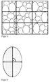
- two parallel lines in the x-direction and two parallel lines in the y-direction were respectively placed in the optical micrograph.
- the lines divide the recording into three equally wide stripes. This is schematically in FIG. 3 shown.
- this length L is taken as a grain size.
- a grain size is obtained.
- two values for a grain both of which are included in the determination of the particle size distribution.
- d 5 , d 50 and d 95 values and the arimethical mean d arith can be determined.
- the d 50 value which is frequently also referred to as median value
- 50% of the grains have a diameter which is smaller than the d 50 value.
- 5% of the grains have a diameter smaller than this d 5 value
- the d 95 value 95% of the grains have a diameter smaller than this d 95 value.
- the arithmetic mean of the particle size distribution results from the sum of the grain sizes of the individual grains divided by the number of cut grains.
- the grain sizes are determined by a line-cutting method. Line-cut methods are known to those skilled in the art and are described, for example, in ASTM 112-13.
- the magnification is chosen so that the line grid cuts at least 50 grains.
- Both the grain sizes of the copper or the copper alloy as well as the grain sizes of Al 2 O 3 ; are thus determined in a plane which is parallel to the coated substrate surface or coplanar with it.
- the SEM image is used, which was also used to determine the particle size distribution.
- the form factor is determined for at least 50 grains of the SEM image. Usually, the grains are evaluated, which were also cut in line intersection of the lines.
- the mean grain shape factor of the alumina then results from the arithmetic mean of the shape factors of the individual Al 2 O 3 grains (ie sum of the individual shape factors divided by the number of grains examined).
- the light micrograph was used, which was also used in the determination of the particle size distribution.
- a bonding method which is preferably used for the production of the copper-ceramic substrates according to the invention is described below:
- a typical process, which is preferably used in the context of the present invention for the application of the copper coating on the ceramic substrate is, for example, from the documents US 3,744,120 . US 3,994,430 . EP 0 085 914 A or the DE 23 19 854 A the disclosure of which is incorporated by reference into the present invention.
- this production method disclosed there is common in that a copper foil is first oxidized in such a way that a substantially uniform copper oxide layer results. The resulting copper foil is then positioned on a ceramic substrate and the ceramic substrate / copper foil composite is heated to a bonding temperature between about 1025-1083 ° C, thereby forming a metallized ceramic substrate. The copper foil thus forms a coating after bonding. Finally, the resulting metallized ceramic substrate is cooled.
- DCB process direct copper bonding process
- the bonding of ceramic substrate and copper foil is carried out in an oven, so-called bonding furnaces generally being used.
- Corresponding bonding ovens often referred to as tunnel ovens include under another elongated tunnel-like furnace space (also called muffle) and a transport device with a transport element, for example in the form of a flexible and heat-resistant conveyor belt for transporting the material to be treated by the heated furnace with a heater chamber.
- the ceramic substrates are positioned together with the copper foil on a carrier on the conveyor belt and then passed through in the bonding oven by the conveyor belt driven a heating area in which the required bonding temperature is reached.
- the resulting ceramic substrate / copper foil composite is recooled according to the invention.
- This method can be used in principle for the production of single-sidedly metallized ceramic substrates as well as for the production of double-sided metallized substrates.
- the production of double-sided metallized substrates usually takes place via a two-stage bonding process, i. using a two-stage single-layer process (SLB method).
- a two-stage bonding process is preferably used.
- the ceramic is bonded in two furnace passes to the copper foils on opposite sides of the ceramic substrate.
- a ceramic substrate is first positioned on a carrier and then covered on the overhead, ie on the side facing away from the carrier, with a copper foil.
- this side of the ceramic substrate is connected to the metal layer and subsequently the resulting assembly is cooled.
- the substrate is turned over and in a second bonding step, the other side of the substrate is provided in the same way with a metal layer, ie the copper foil.
- the following examples show how the thermal shock resistance of the copper-ceramic composite can be improved by approximating the symmetry values of the grain size distribution of copper and the grain size distribution of Al 2 O 3 .
- both the top and the bottom of the ceramic substrate was provided with a copper coating.
- the copper coating was first bonded to one side of the ceramic substrate by means of the SLB process.
- the opposite side of the ceramic substrate was made by the SLB method with another copper coating, so that a copper-ceramic substrate is formed in which a copper foil is bonded on both sides of the ceramic.
- One of the two copper coatings was subsequently patterned in each sample via an etching process (same structuring for all samples).
- the substrates consisted of 96% by weight of Al 2 O 3 .
- the copper coating each had a thickness of 0.3 mm.
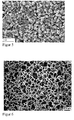
- FIG. 5 shows an SEM image of the surface of the ceramic substrate of KKV 1, by means of which the Al 2 O 3 grain structure was determined.
- FIG. 6 shows a light micrograph of the surface of the copper coating of KKV 1, by means of which the copper grain structure was determined.
Landscapes
- Chemical & Material Sciences (AREA)
- Engineering & Computer Science (AREA)
- Ceramic Engineering (AREA)
- Materials Engineering (AREA)
- Structural Engineering (AREA)
- Organic Chemistry (AREA)
- Inorganic Chemistry (AREA)
- Manufacturing & Machinery (AREA)
- Ceramic Products (AREA)
- Cooling Or The Like Of Semiconductors Or Solid State Devices (AREA)
- Parts Printed On Printed Circuit Boards (AREA)
Abstract
- ein Keramiksubstrat, das Aluminiumoxid enthält,
- eine auf dem Keramiksubstrat vorliegende Beschichtung aus Kupfer oder einer Kupferlegierung,
wobei das Kupfer oder die Kupferlegierung eine Anzahlverteilung der Korngrößen mit einem Medianwert d50, einem arithmetischen Mittelwert darith und einem Symmetriewert S(Cu)=d50/darith aufweist, das Aluminiumoxid eine Anzahlverteilung der Korngrößen mit einem Medianwert d50, einem arithmetischen Mittelwert darith und einem Symmetriewert S(Al2O3)= d50 / darith aufweist, und S(Al2O3) und S(Cu) der folgenden Bedingung genügen: 0,7 ≤ S(Al2O3) / S(Cu) ≤ 1,4.
Description
- Die vorliegende Erfindung betrifft einen Kupfer-Keramik-Verbund sowie ein diesen Verbund enthaltendes Modul, das in Leistungselektronikbauteilen verwendet werden kann.
- Keramikschaltungsträger sind aufgrund ihrer hohen Wärmeleitfähigkeit, hohen Formstabilität bzw. mechanischen Festigkeit sowie ihrer hohen Isolationsfestigkeit insbesondere im Bereich der Hochleistungselektronik von Interesse.
- Für die Metallisierung eines Keramiksubstrats stehen verschiedene Verfahren wie z.B. Direct-Copper-Bonding (üblicherweise als DCB-Verfahren bezeichnet) oder Active-Metal-Brazing (üblicherweise als AMB-Verfahren bezeichnet) zur Verfügung.
- Das nach der Metallisierung des Keramiksubstrats erhaltene Verbundmaterial wird auch als Metall-Keramik-Substrat oder Metall-Keramik-Verbund bezeichnet. Sofern es beispielsweise durch ein DCB-Verfahren hergestellt wurde, wird häufig auch die Bezeichnung "DCB-Substrat" verwendet.
- Bei dem DCB-Verfahren wird ausgenutzt, dass Sauerstoff den Schmelzpunkt des Kupfers von 1083°C auf die eutektische Schmelztemperatur von 1065°C reduziert. Durch die Oxidation von Kupferfolien vor der Metallisierung des Keramiksubstrates oder durch Sauerstoffzufuhr während des Hochtemperaturprozesses (beispielsweise bei einer Temperatur zwischen 1065°C und 1080°C) entsteht eine dünne eutektische Schmelzschicht. Diese reagiert mit der Oberfläche des Keramiksubstrats, so dass Keramik und Metall haftfest miteinander verbunden werden können.
- DCB-Verfahren werden beispielsweise in
US 3,744,120 oderDE 23 19 854 beschriebenen. - Die Metallisierung kann beispielsweise nur auf einer Seite des Keramiksubstrats ("Single-Layer-Bonding" SLB) oder alternativ auch auf beiden Seiten des Keramiksubstrates gleichzeitig ("Double-Layer-Bonding" DLB) erfolgen. Außerdem ist es möglich, zunächst eine erste Seite des Substrats durch einen ersten SLB-Schritt zu metallisieren und anschließend auch die gegenüberliegende Substratseite in einem weiteren SLB-Schritt zu metallisieren.
- Bekannt ist auch, die aufgebrachte Metallbeschichtung für die Ausbildung von Leiterbahnen zu strukturieren, beispielsweise über Ätzverfahren.
- In vielen Anwendungen der Leistungselektronik unterliegt der Metall-Keramik-Verbund hohen Temperaturwechselbelastungen, bei denen deutliche Temperaturänderungen (z.B. im Bereich zwischen -40°C und +150°C) auftreten können.
- Bedingt durch die unterschiedlichen Wärmeausdehnungskoeffizienten des Keramiksubstrats und der Metallbeschichtung ergeben sich am Übergang zwischen diesen Schichten bei Temperaturschwankungen erhebliche mechanische Spannungen, die letztlich zu einer zumindest partiellen Ablösung des Metalls von der Keramikoberfläche führen können. Bekannt ist, dass durch eine spezifische Strukturierung der Metallschicht auf makroskopischer Ebene in ihrem Randbereich Zug- und Druckspannungen verringert und somit die Temperaturwechselbeständigkeit verbessert werden kann.
DE 40 04 844 undDE4318241 A1 beschreiben Metallbeschichtungen auf Keramiksubstraten, die an ihren Kanten Randabschwächungen in Form von Vertiefungen oder Löchern aufweisen. - Neben der Temperaturwechselbeständigkeit sind weitere relevante Eigenschaften eines Kupfer-Keramik-Verbunds für Anwendungen in der Elektronik dessen, Wärmeleitfähigkeit und mechanische Festigkeit (insbesondere die Wärmeleitfähigkeit und mechanische Festigkeit des Keramiksubstrats), ein gutes Bondingverhalten der Kupferbeschichtung gegenüber Bondingdrähten sowie eine möglichst feste Bindung der Metallbeschichtung an die Keramikoberfläche, wobei diese Bindung auch unter längeren Temperaturwechselbelastungen ausreichend fest bleibt sollte.
- In der
DE 10 2012 110 322 wird das Keramiksubstrat des Metall-Keramik-Verbunds hinsichtlich seiner Kornstruktur (also seiner Struktur auf mikroskopischer Ebene) eingehender definiert. Das Keramiksubstrat enthält ein mit Zirkonoxid verstärktes Aluminiumoxid, wobei die mittlere Korngröße des Aluminiumoxids im Bereich von 2-8 µm liegt und das Verhältnis der Länge der Korngrenzen der Al2O3-Körner zu der Gesamtlänge aller Korngrenzen >0,6 ist. Nach den Angaben derDE 10 2012 110 322 trägt diese Kornstruktur zur Verbesserung der Wärmeleitfähigkeit bei. - Eine Aufgabe der vorliegenden Erfindung liegt in der Bereitstellung eines Metall-Keramik-Verbunds mit verbessertem Eigenschaftsprofil, insbesondere mit verbesserter Temperaturwechselbeständigkeit.
- Gelöst wird die Aufgabe durch einen Kupfer-Keramik-Verbund, umfassend
- ein Keramiksubstrat, das Aluminiumoxid enthält,
- eine auf dem Keramiksubstrat vorliegende Beschichtung aus Kupfer oder einer Kupferlegierung,
- Wie allgemein bekannt ist, sind charakteristische Werte einer Korngrößenverteilung unter anderem deren d50-Wert, d5-Wert und d95-Wert. Für den d50-Wert, der häufig auch als Medianwert bezeichnet wird, gilt Folgendes: 50% der Körner weisen einen Durchmesser auf, der kleiner ist als der d50-Wert.
Analog gilt für den d5-Wert, dass 5% der Körner einen Durchmesser aufweisen, der kleiner ist als dieser d5-Wert, und für den d95-Wert gilt, dass 95% der Körner einen Durchmesser aufweisen, der kleiner ist als dieser d95-Wert.
Der arithmetische Mittelwert darith einer Korngrößenverteilung ergibt sich aus der Summe der Korngrößen der einzelnen Körner dividiert durch die Körneranzahl. - Die Symmetrie einer Korngrößenverteilung kann über das Verhältnis von Medianwert d50 zu dem arithmetischen Mittelwert darith dieser Verteilung ausgedrückt werden (d.h. durch den Quotienten d50/darith; nachfolgend auch als Symmetriewert S einer Korngrößenverteilung bezeichnet). Je näher der Wert dieses Quotienten bei 1,0 liegt, desto symmetrischer ist die Korngrößenverteilung.
- Im Rahmen der vorliegenden Erfindung wurde überraschend festgestellt, dass sich die Temperaturwechselbeständigkeit eines Kupfer-Keramik-Verbunds verbessern lässt, wenn die Korngrößenverteilung des Kupfers oder der Kupferlegierung der Metallbeschichtung und die Korngrößenverteilung des Aluminiumoxids des Keramiksubstrats ähnliche Symmetriewerte aufweisen und daher der folgenden Bedingung genügen: 0,7 ≤ S(Al2O3) / S(Cu) ≤ 1,4.
- Erfindungsgemäß versteht man unter einer Temperaturwechselbeständigkeit den Widerstand bzw. die Widerstandsfähigkeit der Kupferschicht gegen Delamination von der Keramik eines Kupfer-Keramik-Substrates, wobei der Widerstand in Folge von zumindest einem Temperaturwechsel der Kupferschicht gegenüber der Keramik bestimmt wird. Eine verbesserte Temperaturwechselbeständigkeit bedeutet, dass die Anzahl der widerstandenen Temperaturwechsel sich vergrößert.
- Erfindungsgemäß wird unter einem verbesserten Drahtbonding verstanden, dass die Kraft, mit der der Bonddraht von der Kupferoberfläche eines Kupfer-Keramik-Verbundes abgelöst werden kann, erhöht ist.
- Erfindungsgemäß wird unter einer verbesserten Kupferhaftfestigkeit eine Haftfestigkeit des Kupfers gegenüber dem Kupfer-Keramik-Verbundes verstanden, so dass die Kraft, mit der die gebondete Kupferfolie von der Keramikoberfläche eines Kupfer-Keramik-Verbundes abgelöst werden kann, erhöht ist. Aus der
DE102004012231B4 ist dem Fachmann ein beispielhaftes Meßverfahren bekannt (Figuren 2 und3 derDE102004012231B4 ). - Erfindungsgemäß wird unter einer verbesserten Biegebruchfestigkeit der Keramik verstanden, dass bei einer Drei-Punkt-Biegung die zum Bruch führende Kraft erhöht ist. Dem Fachmann ist beispielsweise zur Biegebruchfestigkeitsbestimmung der Keramik die DIN EN 843-1 (2008). Bevorzugt weicht die Probengeometrie gegenüber der DIN EN 843-1 (2008) dahingehend ab, dass die Proben eine Abmessung von 20 x 40 x 0,38 mm3 oder 20 x 40 x 0,63 mm3 aufweisen.
- Bevorzugter genügen S(Al2O3) und S(Cu) der folgenden Bedingung:


- Bevorzugt weist das Kupfer oder die Kupferlegierung eine Anzahlverteilung der Korngrößen mit einem Medianwert d50 und einem arithmetischen Mittelwert darith auf, wobei das Verhältnis von d50 zu darith (d.h. d50/darith) im Bereich von 0,75 bis 1,10, bevorzugter im Bereich von 0,78 bis 1,05, noch bevorzugter im Bereich von 0,80 bis 1,00 liegt; und hinsichtlich des Aluminiumoxids ist bevorzugt, dass dieses eine Anzahlverteilung der Korngrößen mit einem Medianwert d50 und einem arithmetischen Mittelwert darith aufweist, wobei das Verhältnis von d50 zu darith (d.h. d50/darith) im Bereich von 0,75 bis 1,10, bevorzugter im Bereich von 0,78 bis 1,05, noch bevorzugter im Bereich von 0,80 bis 1,00 liegt; unter der Maßgabe dass S(Al2O3) / S(Cu) die oben genannten Bedingungen erfüllt.
- Im Rahmen der Erfindung konnte ferner festgestellt werden, dass durch Auswahl weiterer Produktparameter Produkteigenschaften verbessert werden konnten.
- Bevorzugt liegen die Korngrößen des Kupfers oder der Kupferlegierung im Bereich von 10 µm bis 300 µm, bevorzugter im Bereich von 15 µm bis 250 µm, noch bevorzugter im Bereich von 20 µm bis 210 µm. In diesem Korngrößenbereich zeigt das Kupfer oder die Kupferlegierung auch dann noch eine gute Haftung auf einem Keramiksubstrat, wenn der Kupfer-Keramik-Verbund über längere Zeiträume Temperaturwechselbelastungen ausgesetzt ist. Gleichzeitig ermöglicht das Kupfer oder die Kupferlegierung mit diesen Korngrößen ein effizientes Drahtbonding. Eine Metallbeschichtung zeigt ein gutes Drahtbonding, wenn sich eine möglichst starke Verbindung zu einem Bonddraht ausbilden lässt und dadurch das Risiko einer unerwünschten Ablösung des Bonddrahts minimiert wird. Im Rahmen der vorliegenden Erfindung sind diese Werte nicht als strikte Unter- und Obergrenzen für die Korngrößenverteilung anzusehen, sondern können um +/- 10% variieren. In einer bevorzugten Ausführungsform handelt es sich jedoch um die Untergrenze, die nicht unterschritten wird, und die Obergrenze, die nicht überschritten wird, der Korngrößenverteilung des Kupfers oder der Kupferlegierung. In dieser bevorzugten Ausführungsform weist daher das Kupfer oder die Kupferlegierung keine Körner auf, die außerhalb der oben genannten Bereiche liegen. Es ist also bevorzugt, dass dmin(Cu) ≥ 10 µm und dmax(Cu) ≤ 300 µm, bevorzugter dmin(Cu) ≥ 15 µm und dmax(Cu) ≤ 250 µm, noch bevorzugter dmin(Cu) ≥ 20 µm und dmax(Cu) ≤ 210 µm, wobei dmin(Cu) und dmax(Cu) die minimalen bzw. maximalen Korngrößen des Kupfers sind.
- Durch Verwendung einer Kupferausgangsfolie mit geeigneter Korngrößenverteilung können die gewünschten Korngrößen im Kupfer-Keramik-Verbund eingestellt werden. Solche Kupferfolien sind kommerziell erhältlich oder können über Standardverfahren erhalten werden. Eine Feineinstellung der Korngrößen kann gegebenenfalls durch eine thermische Behandlung der Ausgangsfolie erfolgen.
- In einer bevorzugten Ausführungsform weist das Kupfer oder die Kupferlegierung eine Anzahlverteilung der Korngrößen auf, in der höchstens 5% der Körner eine Korngröße von weniger als 15 µm, bevorzugt weniger als 20 µm, noch bevorzugter weniger als 25 µm aufweisen; und/oder in der mindestens 95% der Körner eine Korngröße von weniger als 250 µm, bevorzugt weniger als 230 µm, noch bevorzugter weniger als 200 µm aufweisen.
- Bevorzugt weist die Anzahlverteilung der Korngrößen des Kupfers oder der Kupferlegierung einen d95-Wert von ≤ 250 µm, bevorzugter im Bereich von 140 µm bis 250 µm, noch bevorzugter im Bereich von 140 µm bis 230 µm, noch weiter bevorzugt im Bereich von 150 µm bis 200 µm auf. Der d5-Wert der Korngrößen-Anzahlverteilung des Kupfers oder der Kupferlegierung ist bevorzugt ≥ 15 µm; bevorzugter liegt der d5-Wert im Bereich von 15 µm bis 80 µm, noch bevorzugter im Bereich von 20 µm bis 75 µm, noch weiter bevorzugt im Bereich von 25 µm bis 70 µm Damit kann eine weitere Optimierung der Temperaturwechselbeständigkeit und des Bondingverhaltens des Kupfers oder der Kupferlegierung erzielt werden.
- Ein bevorzugter d50-Wert der Korngrößen-Anzahlverteilung des Kupfers oder der Kupferlegierung liegt beispielsweise im Bereich von 55 µm bis 115 µm.
- Im Rahmen der vorliegenden Erfindung kann es bevorzugt sein, dass die d5-, d95- und d50-Werte der Korngrößen-Anzahlverteilung des Kupfers oder der Kupferlegierung so gewählt werden, dass sie der folgenden Bedingung genügen:

- Die Breite der Korngrößenverteilung kann durch das Verhältnis von d5-Wert zu d95-Wert ausgedrückt werden. In einer bevorzugten Ausführungsform weist das Kupfer oder die Kupferlegierung eine Anzahlverteilung der Korngrößen mit einem d5-Wert und einem d95-Wert auf, wobei das Verhältnis von d5 zu d95 im Bereich von 0,1 bis 0,4, bevorzugter im Bereich von 0,11 bis 0,35, noch bevorzugter im Bereich von 0,12 bis 0,30 liegt. Damit kann eine weitere Optimierung der Temperaturwechselbeständigkeit und der Drahtbondingeigenschaften erzielt werden.
- Eine weitere Optimierung der Temperaturwechselbeständigkeit kann erzielt werden, wenn die Körner der Kupferbeschichtung in ihrer zweidimensionalen Projektion in einer Ebene parallel zur Oberfläche des Keramiksubstrats eine Form aufweisen, die möglichst kreisförmig bzw. rund ist. Die Form eines individuellen Korns lässt sich über seinen Formfaktor RK ausdrücken, der das Verhältnis des maximalen Korndurchmessers dK,max zu dem senkrecht zu dK,max verlaufenden Durchmesser dK,ortho, bestimmt auf halber Länge von dK,max, ist (d.h. RK=dK,ortho/dK,max).
- Aus dem arithmetischen Mittelwert der Formfaktoren RK der Körner erhält man den mittleren Korn-Formfaktor Ra(Cu) des Kupfers oder der Kupferlegierung. Enthält ein Kupfermaterial beispielsweise einen hohen Anteil länglicher Körner, so wird der mittlere Korn-Formfaktor dieses Kupfers einen relativ niedrigen Wert annehmen. Andererseits gilt, dass sich der mittlere Korn-Formfaktor umso mehr dem Wert 1,0 annähert, je höher der Anteil von runden, kreisförmigen Körnern ist.
- Bevorzugt ist der mittlere Korn-Formfaktor Ra(Cu) des Kupfers oder der Kupferlegierung ≥0,40, noch bevorzugter ≥0,60 oder ≥0,80. Geeignete Methoden, mit denen die Form der Körner im Kupfer, beispielsweise bereits in der Kupferausgangsfolie, eingestellt werden können, sind dem Fachmann bekannt. Beispielsweise kann die Kornform in einer Kupferfolie durch eine geeignete Verarbeitungstemperatur oder einen Walzprozess beeinflusst werden. Kupferausgangsfolien, mit denen im finalen Kupfer-Keramik-Verbund der oben angegebene mittlere Korn-Formfaktor Ra(Cu) realisiert werden kann, sind kommerziell erhältlich oder können über Standardverfahren erhalten werden.
- Eine geeignete Dicke der Beschichtung aus Kupfer oder einer Kupferlegierung in einem Kupfer-Keramik-Verbund ist dem Fachmann bekannt. Wie nachfolgend noch erläutert, kann an einigen Stellen der Beschichtung, insbesondere in Randbereichen, ein Teil des Kupfers oder der Kupferlegierung wieder abgetragen werden, beispielsweise zur Ausbildung von Randabschwächungen. Daher ist es im Rahmen der vorliegenden Erfindung möglich, dass die Dicke der Metallbeschichtung variiert. Üblicherweise weist die Beschichtung aus Kupfer oder einer Kupferlegierung über mindestens 70% ihrer Fläche eine Dicke im Bereich von 0.2-1.2 mm auf. Beispielsweise ist es möglich, dass die Dicke etwa 300 µm beträgt.
- Bevorzugt sind die Dicke der Beschichtung aus Kupfer oder einer Kupferlegierung (Dcu) und der Medianwert d50 der Korngrößen-Anzahlverteilung des Kupfers oder der Kupferlegierung so ausgewählt, dass das Verhältnis Dcu zu d50 im Bereich von 0.05 bis 0.40 liegt. Hierzu wird die Dicke Dcu des Kupfers oder der Kupferlegierung an einer Stelle der Beschichtung bestimmt und durch den Medianwert d50 der Korngrößen-Anzahlverteilung des Kupfers oder der Kupferlegierung dividiert. Bevorzugt liegt das Verhältnis Dcu/d50 über mindestens 70%, bevorzugter mindestens 90% der Fläche der Beschichtung aus Kupfer oder einer Kupferlegierung im Bereich von 0,05 bis 0,40.
- Bevorzugt weist das Kupfer der Beschichtung eine Reinheit von ≥ 99,50%, bevorzugter ≥ 99,90%, noch bevorzugter ≥ 99,95% oder sogar ≥ 99,99% auf.
- Bevorzugt wird die Beschichtung aus Kupfer oder einer Kupferlegierung über ein DCB-Verfahren auf das Keramiksubstrat aufgebracht. Wie bereits oben erläutert, kann ein übliches DCB-Verfahren beispielsweise folgende Verfahrensschritte aufweisen:
- Oxidieren einer Kupferfolie, so dass sich an deren Oberfläche eine Kupferoxidschicht bildet;
- Auflegen der Kupferfolie mit der Kupferoxidschicht auf das Keramiksubstrat;
- Erhitzen des Verbundes auf eine Temperatur < 1083°C (z.B. eine Temperatur im Bereich von 1065-1080°C),
- Abkühlen auf Raumtemperatur.
- Als Folge des DCB-Verfahrens können zwischen der Beschichtung aus Kupfer oder einer Kupferlegierung und dem Keramiksubstrat Spinellkristallite vorliegen (z.B. Kupfer-Aluminium-Spinelle).
- Die Beschichtung aus Kupfer oder einer Kupferlegierung kann beispielsweise nur auf einer Seite des Keramiksubstrats angebracht sein. Alternativ ist es möglich, dass beide Seiten (d.h. Ober- und Unterseite) des Keramiksubstrats mit der Beschichtung aus Kupfer oder einer Kupferlegierung versehen sind. Ein beispielhafter Kupfer-Keramik-Verbund, bei dem ein Keramiksubstrat 1 sowohl an seiner Unter- wie auch an seiner Oberseite eine Beschichtung 2 aus Kupfer oder einer Kupferlegierung aufweist, wird in
Figur 1 gezeigt. Ein beispielhafter Kupfer-Keramik-Verbund, bei dem das Keramiksubstrat 1 mehrere Bereiche aufweist, die jeweils mit einer Beschichtung 2 aus Kupfer oder Kupferlegierung versehen sind, wird inFigur 2 gezeigt. Wie nachfolgend noch erläutert wird, können die einzelnen metallisierten Bereiche durch Sollbruchlinien (nicht gezeigt inFigur 2 ) voneinander getrennt sein, so dass durch Brechen entlang dieser Sollbruchlinien eine Vereinzelung dieser Bereiche erfolgen kann. - Zur Ausbildung elektrischer Kontaktflächen kann die Beschichtung aus Kupfer oder einer Kupferlegierung zumindest teilweise eine Strukturierung aufweist. Die Strukturierung der Metallbeschichtung kann in bekannter Weise erfolgen, insbesondere über ein Ätzverfahren (beispielsweise unter Verwendung einer Ätzmaske).
- In dem Ätzverfahren kann das Kupfer oder die Kupferlegierung in Teilbereichen vollständig entfernt werden, so dass in diesen Teilbereichen die Oberfläche des Keramiksubstrats freigelegt wird. Weiterhin ist es auch möglich, dass die Beschichtung aus Kupfer oder einer Kupferlegierung eine oder mehrere Vertiefungen (bevorzugt runde Vertiefungen) aufweist, die beispielsweise in dem Ätzverfahren dadurch erhalten werden, dass beispielsweise das Kupfer oder die Kupferlegierung in dem Bereich der anzubringenden Vertiefung nur teilweise entfernt und die Oberfläche des Keramiksubstrats in diesem Bereich daher noch mit Kupfer oder Kupferlegierung belegt ist. Alternativ oder ergänzend ist es möglich, die Vertiefungen durch das Kupfer oder die Kupferleigerung hindurch bis auf die Keramikoberfläche freizuätzen. Hinsichtlich der möglichen Anordnung solcher Vertiefungen, bevorzugt im Randbereich der Beschichtungen aus Kupfer oder Kupferlegierung, kann beispielsweise auf
DE 40 04 844 C1 undDE 43 18 241 A1 verwiesen werden. - Wie oben ausgeführt, enthält das Keramiksubstrat Aluminiumoxid (Al2O3).
- Bevorzugt liegen die Korngrößen des Aluminiumoxids im Bereich von 0,01 µm bis 25 µm, bevorzugter im Bereich von 0,3 µm bis 23 µm, noch bevorzugter im Bereich von 0,5 µm bis 20 µm. Mit Korngrößen in diesen Bereich weist das Keramiksubstrat des Kupfer-Keramik-Verbunds sowohl eine hohe mechanische Festigkeit als auch eine hohe Wärmeleitfähigkeit auf. Im Rahmen der vorliegenden Erfindung sind diese Werte nicht als strikte Unter- und Obergrenzen für die Korngrößenverteilung anzusehen, sondern können um +/- 10% variieren. In einer bevorzugten Ausführungsform handelt es sich jedoch um die Untergrenze, die nicht unterschritten wird, und Obergrenzen, die nicht überschritten wird, der Korngrößenverteilung des Aluminiumoxids. In dieser bevorzugten Ausführungsform weist daher das Aluminiumoxid keine Körner auf, die außerhalb der oben genannten Bereiche liegen. Es ist also bevorzugt, dass dmin(Al2O3) ≥ 0,01 µm und dmax(Al2O3) ≤ 25 µm, bevorzugter dmin(Al2O3) ≥ 0,3 µm und dmax(Al2O3) ≤ 23 µm, noch bevorzugter dmin(Al2O3) ≥ 0,5 µm und dmax(Al2O3) ≤ 20 µm, wobei dmin(Al2O3) und dmax(Al2O3) die minimalen bzw. maximalen Korngrößen des Aluminiumoxids sind.
- Durch Verwendung eines Keramik-Ausgangsmaterials mit geeigneter Al2O3-Korngrößenverteilung können die gewünschten Al2O3-Korngrößen im Kupfer-Keramik-Verbund eingestellt werden. Solche Keramikmaterialien sind kommerziell erhältlich oder können über Standardverfahren erhalten werden. Eine Feineinstellung der Korngrößen kann gegebenenfalls durch eine thermische Behandlung des Keramik-Ausgangsmaterials erfolgen.
- Wie oben bereits erwähnt, wird im Rahmen der vorliegenden Erfindung die Verteilung der Korngrößen auf Basis der Körneranzahl bestimmt. Bei der Verteilung der Korngrößen handelt es sich also um eine Anzahlverteilung.
- In einer bevorzugten Ausführungsform weist das Aluminiumoxid des Keramiksubstrats eine Anzahlverteilung der Korngrößen auf, in der höchstens 5% der Körner eine Korngröße von weniger als 0,1 µm, bevorzugter weniger als 0,3 µm, noch bevorzugter weniger als 0,5 µm aufweisen; und/oder in der mindestens 95% der Körner eine Korngröße von weniger als 15 µm, bevorzugter weniger als 10 µm, noch bevorzugter weniger als 7 µm aufweisen.
- Eine weitere Optimierung der mechanischen Festigkeit und der Wärmeleitfähigkeit des Keramiksubstrats in dem Metall-Keramik-Verbund kann erzielt werden, wenn die d5- und d95-Werte der Korngrößenverteilung des Al2O3 bestimmten Anforderungen genügen.
- Bevorzugt weist die Anzahlverteilung der Korngrößen des Aluminiumoxids einen d95-Wert von ≤ 15,0 µm, bevorzugter im Bereich von 4,0 µm bis 15,0 µm, noch bevorzugter im Bereich von 4,5 µm bis 10,0 µm, noch weiter bevorzugt im Bereich von 5,0 µm bis 8,0 µm auf. Der d5-Wert der Korngrößen-Anzahlverteilung des Aluminiumoxids ist bevorzugt ≥ 0,1 µm; bevorzugter liegt der d5-Wert im Bereich von 0,1 µm bis 2,5 µm, noch bevorzugter im Bereich von 0,3 µm bis 2,5 µm, noch weiter bevorzugt im Bereich von 0,5 µm bis 2,0 µm. Damit kann eine weitere Optimierung der mechanischen Festigkeit und der Wärmeleitfähigkeit des Keramiksubstrats in dem Metall-Keramik-Verbund erzielt werden.
- Ein bevorzugter d50-Wert der Korngrößen-Anzahlverteilung des Aluminiumoxids liegt beispielsweise im Bereich von 1,0 µm bis 3,0 µm.
- Im Rahmen der vorliegenden Erfindung kann es bevorzugt sein, dass die d5-, d95- und d50-Werte der Korngrößen-Anzahlverteilung des Aluminiumoxids so gewählt werden, dass sie der folgenden Bedingung genügen:

Geeignete Methoden, mit denen die Symmetrie der Korngrößenverteilung im Aluminiumoxid, beispielsweise bereits bei der Herstellung des Ausgangssubstrats, eingestellt werden können, sind dem Fachmann bekannt. Beispielsweise kann die Symmetrie der Korngrößenverteilung durch Sinterdauer und Sintertemperatur bei der Herstellung des Ausgangssubstrats beeinflusst werden. Al2O3-Substrate, mit denen im finalen Kupfer-Keramik-Verbund die oben angegebenen Symmetriewerte realisiert werden können, sind kommerziell erhältlich oder können über Standardverfahren erhalten werden. - Die Breite der Korngrößenverteilung kann durch das Verhältnis von d5-Wert zu d95-Wert ausgedrückt werden. In einer bevorzugten Ausführungsform weist das Aluminiumoxid eine Anzahlverteilung der Korngrößen mit einem d5-Wert und einem d95-Wert auf, wobei das Verhältnis von d5 zu d95 im Bereich von 0,1 bis 0,4, bevorzugter im Bereich von 0,11 bis 0,35, noch bevorzugter im Bereich von 0,12 bis 0,30 liegt. Damit kann eine weitere Optimierung der mechanischen Festigkeit und Wärmeleitfähigkeit des Keramiksubstrats im Metall-Keramik-Verbund erzielt werden.
- Eine weitere Optimierung der mechanischen Festigkeit kann erzielt werden, wenn die Körner des Aluminiumoxids in ihrer zweidimensionalen Projektion in einer Ebene parallel zur Oberfläche des Keramiksubstrats eine Form aufweisen, die möglichst kreisförmig bzw. rund ist. Die Form eines individuellen Al2O3-Korns lässt sich über seinen Formfaktor RK ausdrücken, der das Verhältnis des maximalen Korndurchmessers dmax zu dem senkrecht zu dmax verlaufenden Durchmesser dortho, bestimmt auf halber Länge von dmaX, ist (d.h. RK= dortho/dmax).
- Aus dem arithmetischen Mittelwert der Formfaktoren RK der Al2O3-Körner erhält man den mittleren Korn-Formfaktor Ra(Al2O3) des Aluminiumoxids. Enthält ein Aluminiumoxidmaterial beispielsweise einen hohen Anteil länglicher Körner, so wird der mittlere Korn-Formfaktor dieses Kupfers einen relativ niedrigen Wert aufweisen. Andererseits gilt, dass sich der mittlere Korn-Formfaktor umso mehr dem Wert 1,0 annähert, je höher der Anteil von relativ runden, kreisförmigen Körnern ist.
- Bevorzugt ist der mittlere Korn-Formfaktor Ra(Al2O3) des Aluminiumoxids ≥0,40, noch bevorzugter ≥0,60 oder ≥0,80. Geeignete Methoden, mit denen die Form der Aluminiumoxidkörner, beispielsweise bereits bei der Herstellung des Ausgangssubstrats, eingestellt werden können, sind dem Fachmann bekannt. Beispielsweise kann die Form der Al2O3-Körner durch Sinterdauer und Sintertemperatur bei der Herstellung des Ausgangssubstrats beeinflusst werden. Al2O3-Substrate, mit denen im finalen Kupfer-Keramik-Verbund der oben angegebene Formfaktor Ra(Al2O3) realisiert werden kann, sind kommerziell erhältlich oder können über Standardverfahren erhalten werden.
- Eine geeignete Dicke des Keramiksubstrats in einem Kupfer-Keramik-Verbund ist dem Fachmann bekannt. Üblicherweise weist das Keramiksubstrat über mindestens 70% seiner Fläche, bevorzugter mindestens 90% seiner Fläche eine Dicke im Bereich von 0.2-1.2 mm auf. Eine Dicke des Keramiksubstrates ist beispielsweise etwa 0,38 mm oder etwa 0,63 mm.
- Bevorzugt sind die Dicke des Keramiksubstrats (Dcer) und der Medianwert d50 der Korngrößen-Anzahlverteilung des Aluminiumoxids im Keramiksubstrat so ausgewählt, dass das Verhältnis Dcer zu d50 (d.h. Dcer / d50) im Bereich von 0,001 bis 0,01, bevorzugter im Bereich von 0,002 bis 0,009, noch bevorzugter im Bereich von 0,004 bis 0,008 liegt. Hierzu wird die Dicke Dcer des Keramiksubstrats an einer Stelle bestimmt und durch den Medianwert d50 der Korngrößen-Anzahlverteilung des Aluminiumoxids dividiert. Bevorzugt liegt das Verhältnis Dcer/d50 über mindestens 70%, bevorzugter mindestens 90% der Fläche des Keramiksubstrats im Bereich von 0,05 bis 0,40.
- Optional kann das Aluminiumoxid noch mit Zirkonoxid (ZrO2) verstärkt sein. Ein solches ZrO2-verstärktes Al2O3; enthält, bezogen auf seine Gesamtmasse, das Zirkonoxid üblicherweise in einem Anteil von 0,5-30 Gew%. Das Zirkonoxid wiederum kann optional mit einem oder mehreren Dotieroxid(en), insbesondere Yttriumoxid, Calciumoxid, Ceroxid oder Magnesiumoxid, dotiert sein, üblicherweise in einem Anteil von bis zu 0,01 Gew% oder sogar bis zu 5 Gew%, bezogen auf die Gesamtmasse Zirkonoxid und Aluminiumoxid.
- Bevorzugt enthält das Keramiksubstrat mindestens 65 Gew% Al2O3. Sofern kein ZrO2 zur Verstärkung des Al2O3; vorliegt, kann das Keramiksubstrat beispielsweise zu mindestens 95 Gew%, bevorzugter 96 Gew% aus Al2O3; bestehen.
- Sofern ein mit ZrO2 verstärktes Aluminiumoxid verwendet wird (wobei das ZrO2, wie oben erwähnt, optional noch dotiert ist), kann das Keramiksubstrat beispielsweise zu mindestens 96 Gew%, bevorzugter zu mindestens 98 Gew% aus diesem ZrO2-verstärkten Al2O3; bestehen.
- Das Keramiksubstrat kann beispielsweise eine Wärmeleitfähigkeit von ≥ 20 W/mK, und/oder eine Biegebruchfestigkeit von ≥ 400 MPa aufweisen.
- Das Keramiksubstrat kann in Form eines Einzelsubstrats vorliegen. Alternativ ist es auch möglich, dass das Keramiksubstrat eine oder mehrere (bevorzugt geradlinig verlaufende) Sollbruchlinien aufweist, die das Keramiksubstrat in zwei oder mehr Bereiche unterteilen und zumindest in einem dieser Bereiche eine Beschichtung aus Kupfer oder einer Kupferlegierung aufgebracht ist. Hinsichtlich des Aufbaus eines solchen Mehrfachsubstrats mit Sollbruchlinien kann beispielhaft auf
DE 43 19 944 A1 undDE 199 27 046 A1 verwiesen werden. - Geeignete Abmessungen (Länge x Breite) des Keramiksubstrats (entweder als Einzelsubstrat oder auch als Mehrfachsubstrat) in einem Metall-Keramik-Verbund sind dem Fachmann bekannt. Beispielsweise kann das Keramiksubstrat eine Abmessung, Länge x Breite, von (180-200 mm) x (130-150 mm) oder (180-200 mm) x (270-290 mm) aufweisen. Auch kleinere Abmessungen, beispielsweise (8-12 mm) x (8-12 mm), sind möglich.
- In einer bevorzugten Ausführungsform weist das Aluminiumoxid Korngrößen im Bereich von dmin(Al2O3) bis dmax(Al2O3) auf, das Kupfer oder die Kupferlegierung weist Korngrößen im Bereich von dmin(Cu) bis dmax(Cu) auf,
und die Verhältnisse von dmin(Al2O3) zu dmax(Cu) und von dmax(Al2O3) zu dmin(Cu) genügen folgenden Bedingungen (i) und (ii): - (i)

- (ii)

- Noch bevorzugter genügen die Verhältnisse von dmin(Al2O3) zu dmaX(Cu) und von dmax(Al2O3) zu dmin(Cu) folgenden Bedingungen (i) und (ii):
- (i)

- (ii)

- (i)

- (ii)

- (i)

- (ii)

- In einer bevorzugten Ausführungsform liegt das Verhältnis von d50(Al2O3) zu d50(Cu) im Bereich von 0,008 bis 0,055, bevorzugter im Bereich von 0,010 bis 0,045.
Damit kann eine weitere Optimierung der Adhäsion und Temperaturwechselbeständigkeit in dem Metall-Keramik-Verbund erzielt werden kann - In einer bevorzugten Ausführungsform genügen der mittlere Korn-Formfaktor des Aluminiumoxids Ra(Al2O3) und der mittlere Korn-Formfaktor des Kupfers oder der Kupferlegierung Ra(Cu) der folgenden Bedingung: 0,5≤Ra(Al2O3) / Ra(Cu) <2,0.
- Noch bevorzugter gilt


- Weiterhin betrifft die vorliegende Erfindung ein Modul, enthaltend zumindest einen Kupfer-Keramik-Verbund gemäß der obigen Beschreibung und einen oder mehrere Bonddrähte. Üblicherweise sind der Bonddraht oder die Bonddrähte mit der Beschichtung aus Kupfer oder Kupferlegierung verbunden. Geeignete Bondingverfahren zum Verbinden von Drähten mit einer Metallbeschichtung sind dem Fachmann bekannt. Das Modul kann außerdem ein oder mehrere elektronische Bauteile wie z.B. einen oder mehrere Chips enthalten.
- Die Kornstrukturen des Aluminiumoxids des Keramiksubstrats sowie des Kupfers bzw. der Kupferlegierung der Metallbeschichtung werden im Rahmen der vorliegenden Erfindung folgendermaßen bestimmt:
- Von der Oberfläche des Keramiksubstrats wird eine rasterelektronenmikroskopische Aufnahme (REM-Aufnahme) gemacht. Eine spezielle Probenpräparation in Form eines Schliffbildes ist nicht erforderlich. Die REM-Aufnahme wird an einer Stelle des Keramiksubstrats gemacht, die zuvor mit Kupfer belegt war und durch Ätzen freigelegt wurde.
- Die Korngrößen werden über ein Linienschnittverfahren bestimmt. Linienschnittverfahren sind dem Fachmann bekannt und werden beispielsweise in ASTM 112-13 beschrieben.
- Die Vergrößerung wird so gewählt, dass durch das Linienraster mindestens 50 Al2O3-Körner geschnitten werden. Sofern das Keramiksubstrat noch Körner anderer chemischer Zusammensetzung, beispielsweise ZrO2-Körner, enthält, lassen sich diese in der REM-Aufnahme mit Hilfe von Sekundärelektronenkontrast gut von den Al2O3-Körnern unterscheiden und werden somit nicht in die weiterfolgenden Berechnungen einbezogen.
- In der vorliegenden Erfindung wurden jeweils 2 parallele Linien in x-Richtung und zwei parallele Linien in y-Richtung in die lichtmikroskopische Aufnahme gelegt. Die Linien unterteilen die Aufnahme jeweils in drei gleichmäßig breite Streifen. Dies ist schematisch in
Figur 3 gezeigt. Wenn ein Korn von einer dieser Linien über eine Länge L hinweg geschnitten wird, so wird diese Länge L als Korngröße genommen. Für jedes von einer dieser Linien geschnittene Korn erhält man so eine Korngröße. Am Kreuzungspunkt zweier Linien erhält man für ein Korn zwei Werte, die beide in die Bestimmung der Korngrößenverteilung eingehen. - Aus den Korngrößen der geschnittenen Körner ergibt sich eine Korngrößenverteilung, aus der wiederum die d5-, d50- und d95-Werte sowie der arimethische Mittelwert darith bestimmt werden können.
Wie oben bereits erläutert und dem Fachmann allgemein bekannt ist, gilt für den d50-Wert, der häufig auch als Medianwert bezeichnet wird, Folgendes: 50% der Körner weisen einen Durchmesser auf, der kleiner ist als der d50-Wert. Analog gilt für den d5-Wert, dass 5% der Körner einen Durchmesser aufweisen, der kleiner ist als dieser d5-Wert, und für den d95-Wert gilt, dass 95% der Körner einen Durchmesser aufweisen, der kleiner ist als dieser d95-Wert. - Der arithmetische Mittelwert der Korngrößenverteilung ergibt sich aus der Summe der Korngrößen der einzelnen Körner dividiert durch die Anzahl der geschnittenen Körner.
- Von der Oberfläche der Beschichtung aus Kupfer oder einer Kupferlegierung (parallel zur beschichteten Substratoberfläche) wird eine lichtmikroskopische Aufnahme gemacht. Eine spezielle Probenpräparation in Form eines Schliffbildes ist nicht erforderlich.
- Die Korngrößen werden über ein Linienschnittverfahren bestimmt. Linienschnittverfahren sind dem Fachmann bekannt und werden beispielsweise in ASTM 112-13 beschrieben.
- Die Vergrößerung wird so gewählt, dass durch das Linienraster mindestens 50 Körner geschnitten werden.
- Hinsichtlich der weiteren Auswertung über das Linienschnittverfahren kann auf die oben bei dem Aluminiumoxid gemachten Ausführungen verwiesen werden.
- Sowohl die Korngrößen des Kupfers bzw. der Kupferlegierung wie auch die Korngrößen des Al2O3; werden also in einer Ebene bestimmt, die parallel zur beschichteten Substratoberfläche verläuft oder koplanar mit dieser ist.
- Es wird die REM-Aufnahme herangezogen, die auch bei der Bestimmung der Korngrößenverteilung verwendet wurde.
- Für die Bestimmung des Formfaktors eines individuellen Korns wird folgendermaßen vorgegangen:
- Es wird dessen längste Abmessung dK,max bestimmt. Anschließend wird auf halber Länge von dK,max der senkrecht zu dK,max verlaufende Durchmesser dK,ortho des Korns bestimmt. Der Formfaktor des individuellen Korns RK ergibt sich aus dem Verhältnis von dK,ortho zu dK,max, d.h. RK = dK,ortho / dk,max.
- Dies ist schematisch in
Figur 4 anhand eines Korns mit elliptischer Kornstruktur dargestellt. Je mehr sich die Form eines Korns in seiner zweidimensionalen Projektion derjenigen eines Kreises annähert, desto mehr nähert sich der Formfaktor des Korns dem Wert 1,0 an. Der Formfaktor ist daher auch ein Maß für die Kreisförmigkeit/Rundheit der Körner. - Der Formfaktor wird für mindestens 50 Körner der REM-Aufnahme bestimmt. Es werden üblicherweise die Körner ausgewertet, die auch im Linienschnittverfahren von den Linien geschnitten wurden.
- Der mittlere Korn-Formfaktor des Aluminiumoxids ergibt sich dann aus dem arithmetischen Mittelwert der Formfaktoren der individuellen Al2O3-Körner (d.h. Summe der individuellen Formfaktoren dividiert durch die Anzahl der untersuchten Körner).
- Es wird die lichtmikroskopische Aufnahme herangezogen, die auch bei der Bestimmung der Korngrößenverteilung verwendet wurde.
- Hinsichtlich der Bestimmung des Formfaktors individueller Körner sowie des mittleren Korn-Formfaktors des Kupfers oder der Kupferlegierung kann auf die oben beim Al2O3 gemachten Ausführungen verwiesen werden.
- Sowohl die Korn-Formfaktoren des Kupfers bzw. der Kupferlegierung wie auch die Korn-Formfaktoren des Al2O3; werden also in einer Ebene bestimmt, die parallel zur beschichteten Substratoberfläche verläuft oder koplanar mit dieser ist.
- Nachfolgend wird ein Bonding-Verfahren beschrieben, welches zur Herstellung der erfindungsgemäßen Kupfer-Keramik-Substrate bevorzugt verwendet wird:
- Ein typischer Verfahrensprozess, der im Rahmen der vorliegenden Erfindung bevorzugt für das Aufbringen der Kupferbeschichtung auf das Keramiksubstrat verwendet wird, ist beispielsweise aus den Druckschriften
US 3,744,120 ,US 3,994,430 ,EP 0 085 914 A oder derDE 23 19 854 A bekannt, deren entsprechende Offenbarung durch Bezugnahme in die vorliegende Erfindung eingeschlossen wird. - Diesen dort offenbarten Herstellungsverfahren ist beispielsweise im Rahmen des Direct-Copper-Bonding-Prozesses (DCB-Prozess) gemeinsam, dass eine Kupferfolie zunächst derartig oxidiert wird, dass sich eine im Wesentlichen gleichmäßige Kupferoxidschicht ergibt. Die resultierende Kupferfolie wird dann auf ein Keramik-Substrat positioniert und der Verbund aus Keramik-Substrat und Kupferfolie wird auf eine Prozess- bzw. Bondtemperatur zwischen etwa 1025 und 1083 °C erwärmt, wodurch es zu der Ausbildung eines metallisierten Keramik-Substrats kommt. Die Kupferfolie stellt nach dem Bonden somit eine Beschichtung dar. Abschließend wird das resultierende metallisierte Keramik-Substrat abgekühlt.
- Die Durchführung des Verbindens von Keramik-Substrat und Kupferfolie erfolgt in einem Ofen, wobei im Allgemeinen sogenannte Bondöfen eingesetzt werden. Entsprechende Bondöfen, häufig auch als Tunnelöfen bezeichnet, umfassen unter anderem einen langgestreckten tunnelartigen Ofenraum (auch Muffel genannt) sowie eine Transportvorrichtung mit einem Transportelement beispielsweise in Form eines flexiblen und hitzebeständigen Transportbandes zum Transportieren des Behandlungsgutes durch den mit einer Heizeinrichtung beheizten Ofenraum. Die Keramik-Substrate werden zusammen mit der Kupferfolie auf einen Träger auf dem Transportband positioniert und durchlaufen anschließend in dem Bondofen durch das Transportband angetrieben einen Heizbereich, in welchem die erforderliche Bondtemperatur erreicht wird. Am Ende des Bondprozesses wird der resultierende Verbund aus Keramik-Substrat und Kupferfolie gemäß der Erfindung wieder abgekühlt.
- Dieses Verfahren kann grundsätzlich zur Herstellung von einseitig metallisierten Keramik-Substraten sowie auch zur Herstellung von doppelseitig metallisierten Substraten angewendet werden. Dabei erfolgt die Herstellung von doppelseitig metallisierten Substraten in der Regel über einen zweistufigen Bondprozess, d.h. mittels eines zweistufigen Single-Layer-Prozesses (SLB-Verfahren). Im Rahmen der Erfindung wird bevorzugt ein zweistufiger Bondprozess verwendet.
- Bei diesem zweistufigen Bondprozess zur Herstellung von doppelseitig metallisierten Keramik-Substraten gemäß der Erfindung wird die Keramik in zwei Ofendurchläufen mit den Kupferfolien auf den gegenüberliegenden Seiten des Keramik-Substrats verbunden.
Für diesen Zweck wird zunächst ein Keramik-Substrat auf einen Träger positioniert und anschließend auf der obenliegenden, d.h. auf der dem Träger abgewandten Seite, mit einer Kupferfolie bedeckt. Durch Wärmeeinwirkung wird diese Seite des Keramik-Substrats mit der Metallschicht verbunden und anschießend die resultierende Anordnung abgekühlt.
Anschließend wird das Substrat umgedreht und in einem zweiten Bondschritt wird die andere Seite des Substrats auf gleiche Weise mit einer Metallschicht, d.h. der Kupferfolie, versehen. - Es ist möglich Einzel-Teil-Karten herzustellen oder Großkarten, welche mehrere herausbrechbaren Einzelteil-Karten aufweisen.
- Die nachfolgenden Beispiele zeigen, wie die Temperaturwechselbeständigkeit des Kupfer-Keramik-Verbunds verbessert werden kann, wenn die Symmetriewerte der Korngrößenverteilung des Kupfers und der Korngrößenverteilung des Al2O3 einander angenähert werden.
- Es wurden 3 Kupfer-Keramik-Proben über ein DCB-Verfahren hergestellt:
- Kupfer-Keramik-Verbund 1, nachfolgend "K-K-V 1" (erfindungsgemäß)
- Kupfer-Keramik-Verbund 2, nachfolgend "K-K-V 2" (Vergleichsprobe)
- Kupfer-Keramik-Verbund 3, nachfolgend "K-K-V 3" (Vergleichsprobe)
- In jedem dieser drei Kupfer-Keramik-Verbunde wurde sowohl die Ober- wie auch die Unterseite des Keramiksubstrats mit einer Kupferbeschichtung versehen. Die Kupferbeschichtung wurde dabei zunächst mit einer Seite des Keramiksubstrates mittels des SLB-Verfahrens gebondet. Anschließend wurde die gegenüberliegende Seite des Keramiksubstrates mittels des SLB-Verfahrens mit einer weiteren Kupferbeschichtung, so dass ein Kupfer-Keramik-Substrat entsteht, bei dem auf beiden Seiten der Keramik eine Kupferfolie gebondet ist. Jeweils eine der beiden Kupferbeschichtungen wurde in jeder Probe über ein Ätzverfahren nachfolgend strukturiert (gleiche Strukturierung für alle Proben). In allen Beispielen bestanden die Substrate zu 96 Gew% aus Al2O3.
- In jedem dieser 3 Kupfer-Keramik-Verbunde wies das Keramiksubstrat folgende Abmessungen auf:
- Dicke des Keramiksubstrats: 0,38 mm;
- Länge x Breite des Keramiksubstrats: 190 x 140 mm2
- Die Kupferbeschichtung wies jeweils eine Dicke von 0,3 mm auf.
-
Figur 5 zeigt eine REM-Aufnahme der Oberfläche des Keramiksubstrats von K-K-V 1, mittels der die Al2O3-Kornstruktur bestimmt wurde. -
Figur 6 zeigt eine lichtmikroskopische Aufnahme von der Oberfläche der Kupferbeschichtung von K-K-V 1, mittels der die Kupfer-Kornstruktur bestimmt wurde. - Für jede dieser 3 Proben wurde die Temperaturwechselbeständigkeit des Metall-Keramik-Verbunds bestimmt, und zwar nach folgender Methode:
- Zur Ermittlung der Temperaturwechselbeständigkeit des Kupfer-Keramik-Substrats wird bevorzugt ein Einzel-Teil-Substrat aus einer Großkarte herausgebrochen. Das Einzelteilsubtrat wurde in einer dem Fachmann bekannten Vorrichtung einem Temperatur-Wechsel-Zyklus unterzogen, der sich zusammensetzt aus:
- Auslagerung bei 150 °C (bevorzugt in einer ersten Kammer eines Temperaturwechselschranks) für 15 Minuten
- Auslagerung bei - 40 °C (minus 40 °C) (bevorzugt in einer zweiten Kammer des Temperaturwechselschranks) für 15 Minuten
- , wobei zwischen der Verlagerung von einer Kammer in die andere Kammer eine Transferzeit von 15 Sekunden liegt.
- Im Rahmen von 5 Zyklen (Auslagerung 150 °C zu -40 °C und zurück entspricht einem Zyklus) wurde jeweils mittels Ultraschallmikroskop die Fläche der Verbindung an der Grenzfläche zwischen Kupfer und Keramik auf Delamination untersucht.
- In der nachfolgenden Tabelle 1 werden für die Proben K-K-V 1, K-K-V 2 und K-K-V 3 die jeweiligen Quotienten der Symmetriewerte der Al2O3- und Kupfer-Korngrößenverteilungen (d.h. S(Al2O3) / S(Cu)) sowie die Ergebnisse der Temperaturwechselbeständigkeitstests zusammengefasst:
Tabelle 1: Temperaturwechselbeständigkeit in Abhängigkeit von S(Al2O3) / S(Cu) Temperaturwechselbeständigkeit Probe K-K-V 1 (erfindungs-gemäß) S(Al2O3) / S(Cu): 0,96 + Probe K-K-V 2 (Vergleich) S(Al2O3) / S(Cu): 0,63 - Probe K-K-V 3 (Vergleich) S(Al2O3) / S(Cu): 1,57 -
das Kupfer oder die Kupferlegierung eine Anzahlverteilung der Korngrößen mit einem Medianwert d50, einem arithmetischen Mittelwert darith und einem Symmetriewert S(Cu) = d50 / darith aufweist,
das Aluminiumoxid eine Anzahlverteilung der Korngrößen mit einem Medianwert d50, einem arithmetischen Mittelwert darith und einem Symmetriewert S(Al2O3)= d50 / darith aufweist,
und S(Al2O3) und S(Cu) der folgenden Bedingung genügen:

Wie oben bereits erwähnt, ist bevorzugt, dass dmin(Cu) ≥ 10 µm und dmax(Cu) ≤ 300 µm, bevorzugter dmin(Cu) ≥ 15 µm und dmax(Cu) ≤ 250 µm, noch bevorzugter dmin(Cu) ≥ 20 µm und dmax(Cu) ≤ 210 µm, wobei dmin(Cu) und dmax(Cu) die minimalen bzw. maximalen Korngrößen des Kupfers sind.
Claims (9)
- Kupfer-Keramik-Verbund, umfassend- ein Keramiksubstrat, das Aluminiumoxid enthält,- eine auf dem Keramiksubstrat vorliegende Beschichtung aus Kupfer oder einer Kupferlegierung,wobei
das Kupfer oder die Kupferlegierung eine Anzahlverteilung der Korngrößen mit einem Medianwert d50, einem arithmetischen Mittelwert darith und einem Symmetriewert S(Cu) = d50 / darith aufweist,
das Aluminiumoxid eine Anzahlverteilung der Korngrößen mit einem Medianwert d50, einem arithmetischen Mittelwert darith und einem Symmetriewert S(Al2O3)= d50 / darith aufweist,
und S(Al2O3) und S(Cu) der folgenden Bedingung genügen:
- Kupfer-Keramik-Verbund nach Anspruch 1, wobei das Kupfer oder die Kupferlegierung Korngrößen im Bereich von 10 µm bis 300 µm, bevorzugter im Bereich von 15 µm bis 250 µm, noch bevorzugter im Bereich von 20 µm bis 210 µm aufweist.
- Kupfer-Keramik-Verbund nach Anspruch 1 oder 2, wobei das Aluminiumoxid Korngrößen im Bereich von 0,01 µm bis 25 µm, bevorzugter im Bereich von 0,3 µm bis 23 µm, noch bevorzugter im Bereich von 0,5 µm bis 20 µm aufweist.
- Kupfer-Keramik-Verbund nach einem der vorstehenden Ansprüche, wobei S(Al2O3) und S(Cu) der folgenden Bedingung:


- Kupfer-Keramik-Verbund nach einem der vorstehenden Ansprüche, wobei das Keramiksubstrat zu mindestens 65 Gew% aus dem Aluminiumoxid besteht.
- Kupfer-Keramik-Verbund nach einem der vorstehenden Ansprüche, wobei die Beschichtung aus Kupfer oder einer Kupferlegierung über ein DCB-Verfahren auf das Keramiksubstrat aufgebracht wird.
- Kupfer-Keramik-Verbund nach einem der vorstehenden Ansprüche, wobei die Beschichtung aus Kupfer oder einer Kupferlegierung zur Ausbildung von elektrischen Kontaktflächen zumindest teilweise eine Strukturierung aufweist.
- Kupfer-Keramik-Verbund nach einem der vorstehenden Ansprüche, wobei die Beschichtung aus Kupfer oder einer Kupferlegierung über mindestens 70% ihrer Fläche eine Dicke im Bereich von 0,2-1,2 mm aufweist; und/oder das Keramiksubstrat über mindestens 70% seiner Fläche eine Dicke im Bereich von 0,2-1,2 mm aufweist.
- Modul, enthaltend zumindest einen Kupfer-Keramik-Verbund gemäß einem der Ansprüche 1-8 und einen oder mehrere Bonddrähte.
Priority Applications (7)
| Application Number | Priority Date | Filing Date | Title |
|---|---|---|---|
| HUE16157639A HUE053117T2 (hu) | 2016-02-26 | 2016-02-26 | Réz-kerámia kompozitok |
| EP16157639.2A EP3210951B9 (de) | 2016-02-26 | 2016-02-26 | Kupfer-keramik-verbund |
| US16/078,141 US11021407B2 (en) | 2016-02-26 | 2017-02-16 | Copper/ceramic composite |
| CN201780012110.1A CN108698936B (zh) | 2016-02-26 | 2017-02-16 | 铜/陶瓷复合物 |
| JP2018544119A JP6817319B2 (ja) | 2016-02-26 | 2017-02-16 | 銅/セラミック複合材 |
| KR1020187025788A KR102206422B1 (ko) | 2016-02-26 | 2017-02-16 | 구리/세라믹 복합체 |
| PCT/EP2017/053452 WO2017144334A1 (de) | 2016-02-26 | 2017-02-16 | Kupfer-keramik-verbund |
Applications Claiming Priority (1)
| Application Number | Priority Date | Filing Date | Title |
|---|---|---|---|
| EP16157639.2A EP3210951B9 (de) | 2016-02-26 | 2016-02-26 | Kupfer-keramik-verbund |
Publications (3)
| Publication Number | Publication Date |
|---|---|
| EP3210951A1 true EP3210951A1 (de) | 2017-08-30 |
| EP3210951B1 EP3210951B1 (de) | 2020-12-09 |
| EP3210951B9 EP3210951B9 (de) | 2021-05-19 |
Family
ID=55443153
Family Applications (1)
| Application Number | Title | Priority Date | Filing Date |
|---|---|---|---|
| EP16157639.2A Active EP3210951B9 (de) | 2016-02-26 | 2016-02-26 | Kupfer-keramik-verbund |
Country Status (7)
| Country | Link |
|---|---|
| US (1) | US11021407B2 (de) |
| EP (1) | EP3210951B9 (de) |
| JP (1) | JP6817319B2 (de) |
| KR (1) | KR102206422B1 (de) |
| CN (1) | CN108698936B (de) |
| HU (1) | HUE053117T2 (de) |
| WO (1) | WO2017144334A1 (de) |
Cited By (2)
| Publication number | Priority date | Publication date | Assignee | Title |
|---|---|---|---|---|
| EP3648156A1 (de) * | 2018-11-02 | 2020-05-06 | Infineon Technologies AG | Halbleitersubstrat |
| EP3855484A4 (de) * | 2018-12-06 | 2022-06-01 | NGK Insulators, Ltd. | Substrat für halbleiterbauelement |
Families Citing this family (1)
| Publication number | Priority date | Publication date | Assignee | Title |
|---|---|---|---|---|
| CN113929486B (zh) * | 2020-06-29 | 2022-12-09 | 比亚迪股份有限公司 | 一种陶瓷覆铜板及其制备方法 |
Citations (12)
| Publication number | Priority date | Publication date | Assignee | Title |
|---|---|---|---|---|
| US3744120A (en) | 1972-04-20 | 1973-07-10 | Gen Electric | Direct bonding of metals with a metal-gas eutectic |
| DE2319854A1 (de) | 1972-04-20 | 1973-10-25 | Gen Electric | Verfahren zum direkten verbinden von metallen mit nichtmetallischen substraten |
| US3994430A (en) | 1975-07-30 | 1976-11-30 | General Electric Company | Direct bonding of metals to ceramics and metals |
| EP0085914A2 (de) | 1982-02-06 | 1983-08-17 | BROWN, BOVERI & CIE Aktiengesellschaft | Verfahren zum direkten Verbinden von Kupferstücken mit Oxidkeramiksubstraten |
| DE4004844C1 (de) | 1990-02-16 | 1991-01-03 | Abb Ixys Semiconductor Gmbh | Verfahren zur Herstellung einer strukturierten Kupfermetallisierung auf einem Keramiksubstrat |
| DE4319944A1 (de) | 1993-06-03 | 1994-12-08 | Schulz Harder Juergen | Mehrfach-Substrat sowie Verfahren zu seiner Herstellung |
| DE4318241A1 (de) | 1993-06-02 | 1994-12-08 | Schulz Harder Juergen | Substrat |
| DE19927046A1 (de) | 1999-06-14 | 2000-12-28 | Schulz Harder Juergen | Keramik-Metall-Substrat, insbesondere Mehrfachsubstrat |
| EP1434265A1 (de) * | 2002-12-27 | 2004-06-30 | Mitsubishi Materials Corporation | Wärmeleitendes, mehrschichtiges Substrat und Substrat für Leistungshalbleitermodul |
| DE102004012231B4 (de) | 2004-03-09 | 2006-03-23 | Curamik Electronics Gmbh | Metall-Keramik-Substrat |
| WO2013015355A1 (ja) * | 2011-07-28 | 2013-01-31 | 株式会社東芝 | 酸化物系セラミックス回路基板の製造方法および酸化物系セラミックス回路基板 |
| DE102012110322A1 (de) | 2012-10-29 | 2014-04-30 | Curamik Electronics Gmbh | Metall-Keramik-Substrat sowie Verfahren zum Herstellen eines Metall-Keramik-Substrates |
Family Cites Families (9)
| Publication number | Priority date | Publication date | Assignee | Title |
|---|---|---|---|---|
| JPS62282797A (ja) | 1986-05-29 | 1987-12-08 | Dowa Mining Co Ltd | セラミツクス−銅直接接合用銅材 |
| DE102004050792A1 (de) * | 2004-10-19 | 2006-04-20 | Robert Bosch Gmbh | Bauelemente-Modul für Hochtemperaturanwendungen und Verfahren zum Herstellen eines derartigen Bauelemente-Moduls |
| DE102009041574A1 (de) | 2008-10-29 | 2010-05-12 | Electrovac Ag | Verbundmaterial, Verfahren zum Herstellen eines Verbundmaterials sowie Kleber oder Bondmaterial |
| JP2010120801A (ja) | 2008-11-19 | 2010-06-03 | Panasonic Corp | セラミックス基板 |
| JP6129738B2 (ja) | 2011-07-14 | 2017-05-17 | 株式会社東芝 | セラミックス回路基板 |
| KR101522807B1 (ko) * | 2011-07-14 | 2015-05-26 | 가부시끼가이샤 도시바 | 세라믹스 회로 기판 |
| JP6130209B2 (ja) * | 2013-05-14 | 2017-05-17 | Dowaエレクトロニクス株式会社 | 導電膜 |
| WO2015129302A1 (ja) | 2014-02-26 | 2015-09-03 | 日本碍子株式会社 | 半導体用複合基板のハンドル基板 |
| CN106537580B (zh) * | 2014-07-29 | 2021-06-11 | 电化株式会社 | 陶瓷电路基板及其制造方法 |
-
2016
- 2016-02-26 HU HUE16157639A patent/HUE053117T2/hu unknown
- 2016-02-26 EP EP16157639.2A patent/EP3210951B9/de active Active
-
2017
- 2017-02-16 CN CN201780012110.1A patent/CN108698936B/zh active Active
- 2017-02-16 WO PCT/EP2017/053452 patent/WO2017144334A1/de not_active Ceased
- 2017-02-16 US US16/078,141 patent/US11021407B2/en active Active
- 2017-02-16 JP JP2018544119A patent/JP6817319B2/ja active Active
- 2017-02-16 KR KR1020187025788A patent/KR102206422B1/ko active Active
Patent Citations (12)
| Publication number | Priority date | Publication date | Assignee | Title |
|---|---|---|---|---|
| US3744120A (en) | 1972-04-20 | 1973-07-10 | Gen Electric | Direct bonding of metals with a metal-gas eutectic |
| DE2319854A1 (de) | 1972-04-20 | 1973-10-25 | Gen Electric | Verfahren zum direkten verbinden von metallen mit nichtmetallischen substraten |
| US3994430A (en) | 1975-07-30 | 1976-11-30 | General Electric Company | Direct bonding of metals to ceramics and metals |
| EP0085914A2 (de) | 1982-02-06 | 1983-08-17 | BROWN, BOVERI & CIE Aktiengesellschaft | Verfahren zum direkten Verbinden von Kupferstücken mit Oxidkeramiksubstraten |
| DE4004844C1 (de) | 1990-02-16 | 1991-01-03 | Abb Ixys Semiconductor Gmbh | Verfahren zur Herstellung einer strukturierten Kupfermetallisierung auf einem Keramiksubstrat |
| DE4318241A1 (de) | 1993-06-02 | 1994-12-08 | Schulz Harder Juergen | Substrat |
| DE4319944A1 (de) | 1993-06-03 | 1994-12-08 | Schulz Harder Juergen | Mehrfach-Substrat sowie Verfahren zu seiner Herstellung |
| DE19927046A1 (de) | 1999-06-14 | 2000-12-28 | Schulz Harder Juergen | Keramik-Metall-Substrat, insbesondere Mehrfachsubstrat |
| EP1434265A1 (de) * | 2002-12-27 | 2004-06-30 | Mitsubishi Materials Corporation | Wärmeleitendes, mehrschichtiges Substrat und Substrat für Leistungshalbleitermodul |
| DE102004012231B4 (de) | 2004-03-09 | 2006-03-23 | Curamik Electronics Gmbh | Metall-Keramik-Substrat |
| WO2013015355A1 (ja) * | 2011-07-28 | 2013-01-31 | 株式会社東芝 | 酸化物系セラミックス回路基板の製造方法および酸化物系セラミックス回路基板 |
| DE102012110322A1 (de) | 2012-10-29 | 2014-04-30 | Curamik Electronics Gmbh | Metall-Keramik-Substrat sowie Verfahren zum Herstellen eines Metall-Keramik-Substrates |
Cited By (4)
| Publication number | Priority date | Publication date | Assignee | Title |
|---|---|---|---|---|
| EP3648156A1 (de) * | 2018-11-02 | 2020-05-06 | Infineon Technologies AG | Halbleitersubstrat |
| CN111146179A (zh) * | 2018-11-02 | 2020-05-12 | 英飞凌科技股份有限公司 | 半导体衬底 |
| US11211307B2 (en) | 2018-11-02 | 2021-12-28 | Infineon Technologies Ag | Semiconductor substrate |
| EP3855484A4 (de) * | 2018-12-06 | 2022-06-01 | NGK Insulators, Ltd. | Substrat für halbleiterbauelement |
Also Published As
| Publication number | Publication date |
|---|---|
| JP2019511991A (ja) | 2019-05-09 |
| KR20180111940A (ko) | 2018-10-11 |
| JP6817319B2 (ja) | 2021-01-20 |
| HUE053117T2 (hu) | 2021-06-28 |
| US20200308072A1 (en) | 2020-10-01 |
| WO2017144334A1 (de) | 2017-08-31 |
| CN108698936B (zh) | 2021-05-07 |
| EP3210951B9 (de) | 2021-05-19 |
| CN108698936A (zh) | 2018-10-23 |
| KR102206422B1 (ko) | 2021-01-22 |
| EP3210951B1 (de) | 2020-12-09 |
| US11021407B2 (en) | 2021-06-01 |
Similar Documents
| Publication | Publication Date | Title |
|---|---|---|
| DE10141910B4 (de) | Glaskeramiksinterprodukt und Verfahren zu seiner Herstellung | |
| EP3419950B1 (de) | Kupfer-keramik-verbund | |
| DE10024236A1 (de) | Keramikkondensator und Verfahren zu seiner Herstellung | |
| DE102012110322A1 (de) | Metall-Keramik-Substrat sowie Verfahren zum Herstellen eines Metall-Keramik-Substrates | |
| DE112018000457T5 (de) | Isoliertes wärmeableitungssubstrat | |
| DE102022113414A1 (de) | Verbundmaterial und Wärmeableitungsteil hieraus | |
| DE112006002451B4 (de) | Keramisches mehrlagiges Substrat, keramisches mehrlagiges Modul und Verfahren zum Herstellen desselben | |
| EP3419952B1 (de) | Kupfer-keramik-verbund | |
| EP3419949B1 (de) | Kupfer-keramik-verbund | |
| EP3210956B1 (de) | Kupfer-keramik-verbund | |
| EP3210951B1 (de) | Kupfer-keramik-verbund | |
| EP3419951B1 (de) | Kupfer-keramik-verbund | |
| DE69934909T2 (de) | Substrat auf der basis eines siliziumnitridkomposits | |
| EP4237390B1 (de) | Kupfer-keramik-substrat | |
| EP3210957B1 (de) | Kupfer-keramik-verbund | |
| DE112021000182T5 (de) | Keramiksinterkörper und Substrat für eine Halbleitervorrichtung | |
| DE102016203097B3 (de) | Kupfer-Keramik-Verbund und Modul | |
| DE102017128308A1 (de) | Verfahren zur Herstellung eines Metall-Keramik-Substrats, Verfahren zur Herstellung eines Metallhalbzeugs und Metall-Keramik-Substrat | |
| DE202016008371U1 (de) | Kupfer-Keramik-Verbund | |
| EP1497838A1 (de) | Ptc-bauelement und verfahren zu dessen herstellung | |
| DE202016008370U1 (de) | Kupfer-Keramik-Verbund | |
| DE202016008286U1 (de) | Kupfer-Keramik-Verbund | |
| DE202016008287U1 (de) | Kupfer-Keramik-Verbund | |
| DE202016008307U1 (de) | Kupfer-Keramik-Verbund | |
| DE112022007831T5 (de) | Substrat für eine halbleitervorrichtung und verfahren zur herstellung davon |
Legal Events
| Date | Code | Title | Description |
|---|---|---|---|
| REG | Reference to a national code |
Ref country code: DE Ref legal event code: R138 Ref document number: 202016008370 Country of ref document: DE Free format text: GERMAN DOCUMENT NUMBER IS 502016011891 |
|
| PUAI | Public reference made under article 153(3) epc to a published international application that has entered the european phase |
Free format text: ORIGINAL CODE: 0009012 |
|
| STAA | Information on the status of an ep patent application or granted ep patent |
Free format text: STATUS: THE APPLICATION HAS BEEN PUBLISHED |
|
| AK | Designated contracting states |
Kind code of ref document: A1 Designated state(s): AL AT BE BG CH CY CZ DE DK EE ES FI FR GB GR HR HU IE IS IT LI LT LU LV MC MK MT NL NO PL PT RO RS SE SI SK SM TR |
|
| AX | Request for extension of the european patent |
Extension state: BA ME |
|
| STAA | Information on the status of an ep patent application or granted ep patent |
Free format text: STATUS: REQUEST FOR EXAMINATION WAS MADE |
|
| 17P | Request for examination filed |
Effective date: 20170913 |
|
| RBV | Designated contracting states (corrected) |
Designated state(s): AL AT BE BG CH CY CZ DE DK EE ES FI FR GB GR HR HU IE IS IT LI LT LU LV MC MK MT NL NO PL PT RO RS SE SI SK SM TR |
|
| STAA | Information on the status of an ep patent application or granted ep patent |
Free format text: STATUS: EXAMINATION IS IN PROGRESS |
|
| 17Q | First examination report despatched |
Effective date: 20190220 |
|
| GRAP | Despatch of communication of intention to grant a patent |
Free format text: ORIGINAL CODE: EPIDOSNIGR1 |
|
| STAA | Information on the status of an ep patent application or granted ep patent |
Free format text: STATUS: GRANT OF PATENT IS INTENDED |
|
| INTG | Intention to grant announced |
Effective date: 20200709 |
|
| GRAS | Grant fee paid |
Free format text: ORIGINAL CODE: EPIDOSNIGR3 |
|
| GRAA | (expected) grant |
Free format text: ORIGINAL CODE: 0009210 |
|
| STAA | Information on the status of an ep patent application or granted ep patent |
Free format text: STATUS: THE PATENT HAS BEEN GRANTED |
|
| RIN1 | Information on inventor provided before grant (corrected) |
Inventor name: HERBST, KAI Inventor name: MUSCHELKNAUTZ, CHRISTIAN Inventor name: ROGG, ALEXANDER |
|
| AK | Designated contracting states |
Kind code of ref document: B1 Designated state(s): AL AT BE BG CH CY CZ DE DK EE ES FI FR GB GR HR HU IE IS IT LI LT LU LV MC MK MT NL NO PL PT RO RS SE SI SK SM TR |
|
| REG | Reference to a national code |
Ref country code: GB Ref legal event code: FG4D Free format text: NOT ENGLISH |
|
| REG | Reference to a national code |
Ref country code: AT Ref legal event code: REF Ref document number: 1343284 Country of ref document: AT Kind code of ref document: T Effective date: 20201215 Ref country code: CH Ref legal event code: EP |
|
| REG | Reference to a national code |
Ref country code: DE Ref legal event code: R096 Ref document number: 502016011891 Country of ref document: DE |
|
| REG | Reference to a national code |
Ref country code: IE Ref legal event code: FG4D Free format text: LANGUAGE OF EP DOCUMENT: GERMAN |
|
| REG | Reference to a national code |
Ref country code: CH Ref legal event code: NV Representative=s name: DENNEMEYER AG, CH |
|
| PG25 | Lapsed in a contracting state [announced via postgrant information from national office to epo] |
Ref country code: FI Free format text: LAPSE BECAUSE OF FAILURE TO SUBMIT A TRANSLATION OF THE DESCRIPTION OR TO PAY THE FEE WITHIN THE PRESCRIBED TIME-LIMIT Effective date: 20201209 Ref country code: RS Free format text: LAPSE BECAUSE OF FAILURE TO SUBMIT A TRANSLATION OF THE DESCRIPTION OR TO PAY THE FEE WITHIN THE PRESCRIBED TIME-LIMIT Effective date: 20201209 Ref country code: NO Free format text: LAPSE BECAUSE OF FAILURE TO SUBMIT A TRANSLATION OF THE DESCRIPTION OR TO PAY THE FEE WITHIN THE PRESCRIBED TIME-LIMIT Effective date: 20210309 Ref country code: GR Free format text: LAPSE BECAUSE OF FAILURE TO SUBMIT A TRANSLATION OF THE DESCRIPTION OR TO PAY THE FEE WITHIN THE PRESCRIBED TIME-LIMIT Effective date: 20210310 |
|
| REG | Reference to a national code |
Ref country code: CH Ref legal event code: PK Free format text: BERICHTIGUNG B9 |
|
| PG25 | Lapsed in a contracting state [announced via postgrant information from national office to epo] |
Ref country code: BG Free format text: LAPSE BECAUSE OF FAILURE TO SUBMIT A TRANSLATION OF THE DESCRIPTION OR TO PAY THE FEE WITHIN THE PRESCRIBED TIME-LIMIT Effective date: 20210309 Ref country code: SE Free format text: LAPSE BECAUSE OF FAILURE TO SUBMIT A TRANSLATION OF THE DESCRIPTION OR TO PAY THE FEE WITHIN THE PRESCRIBED TIME-LIMIT Effective date: 20201209 Ref country code: LV Free format text: LAPSE BECAUSE OF FAILURE TO SUBMIT A TRANSLATION OF THE DESCRIPTION OR TO PAY THE FEE WITHIN THE PRESCRIBED TIME-LIMIT Effective date: 20201209 |
|
| REG | Reference to a national code |
Ref country code: NL Ref legal event code: MP Effective date: 20201209 |
|
| REG | Reference to a national code |
Ref country code: HU Ref legal event code: AG4A Ref document number: E053117 Country of ref document: HU |
|
| PG25 | Lapsed in a contracting state [announced via postgrant information from national office to epo] |
Ref country code: NL Free format text: LAPSE BECAUSE OF FAILURE TO SUBMIT A TRANSLATION OF THE DESCRIPTION OR TO PAY THE FEE WITHIN THE PRESCRIBED TIME-LIMIT Effective date: 20201209 Ref country code: HR Free format text: LAPSE BECAUSE OF FAILURE TO SUBMIT A TRANSLATION OF THE DESCRIPTION OR TO PAY THE FEE WITHIN THE PRESCRIBED TIME-LIMIT Effective date: 20201209 |
|
| REG | Reference to a national code |
Ref country code: LT Ref legal event code: MG9D |
|
| PG25 | Lapsed in a contracting state [announced via postgrant information from national office to epo] |
Ref country code: SK Free format text: LAPSE BECAUSE OF FAILURE TO SUBMIT A TRANSLATION OF THE DESCRIPTION OR TO PAY THE FEE WITHIN THE PRESCRIBED TIME-LIMIT Effective date: 20201209 Ref country code: PT Free format text: LAPSE BECAUSE OF FAILURE TO SUBMIT A TRANSLATION OF THE DESCRIPTION OR TO PAY THE FEE WITHIN THE PRESCRIBED TIME-LIMIT Effective date: 20210409 Ref country code: RO Free format text: LAPSE BECAUSE OF FAILURE TO SUBMIT A TRANSLATION OF THE DESCRIPTION OR TO PAY THE FEE WITHIN THE PRESCRIBED TIME-LIMIT Effective date: 20201209 Ref country code: CZ Free format text: LAPSE BECAUSE OF FAILURE TO SUBMIT A TRANSLATION OF THE DESCRIPTION OR TO PAY THE FEE WITHIN THE PRESCRIBED TIME-LIMIT Effective date: 20201209 Ref country code: EE Free format text: LAPSE BECAUSE OF FAILURE TO SUBMIT A TRANSLATION OF THE DESCRIPTION OR TO PAY THE FEE WITHIN THE PRESCRIBED TIME-LIMIT Effective date: 20201209 Ref country code: SM Free format text: LAPSE BECAUSE OF FAILURE TO SUBMIT A TRANSLATION OF THE DESCRIPTION OR TO PAY THE FEE WITHIN THE PRESCRIBED TIME-LIMIT Effective date: 20201209 Ref country code: LT Free format text: LAPSE BECAUSE OF FAILURE TO SUBMIT A TRANSLATION OF THE DESCRIPTION OR TO PAY THE FEE WITHIN THE PRESCRIBED TIME-LIMIT Effective date: 20201209 |
|
| PG25 | Lapsed in a contracting state [announced via postgrant information from national office to epo] |
Ref country code: PL Free format text: LAPSE BECAUSE OF FAILURE TO SUBMIT A TRANSLATION OF THE DESCRIPTION OR TO PAY THE FEE WITHIN THE PRESCRIBED TIME-LIMIT Effective date: 20201209 |
|
| REG | Reference to a national code |
Ref country code: DE Ref legal event code: R097 Ref document number: 502016011891 Country of ref document: DE |
|
| PG25 | Lapsed in a contracting state [announced via postgrant information from national office to epo] |
Ref country code: MC Free format text: LAPSE BECAUSE OF FAILURE TO SUBMIT A TRANSLATION OF THE DESCRIPTION OR TO PAY THE FEE WITHIN THE PRESCRIBED TIME-LIMIT Effective date: 20201209 Ref country code: IS Free format text: LAPSE BECAUSE OF FAILURE TO SUBMIT A TRANSLATION OF THE DESCRIPTION OR TO PAY THE FEE WITHIN THE PRESCRIBED TIME-LIMIT Effective date: 20210409 |
|
| PLBE | No opposition filed within time limit |
Free format text: ORIGINAL CODE: 0009261 |
|
| STAA | Information on the status of an ep patent application or granted ep patent |
Free format text: STATUS: NO OPPOSITION FILED WITHIN TIME LIMIT |
|
| REG | Reference to a national code |
Ref country code: BE Ref legal event code: MM Effective date: 20210228 |
|
| PG25 | Lapsed in a contracting state [announced via postgrant information from national office to epo] |
Ref country code: AL Free format text: LAPSE BECAUSE OF FAILURE TO SUBMIT A TRANSLATION OF THE DESCRIPTION OR TO PAY THE FEE WITHIN THE PRESCRIBED TIME-LIMIT Effective date: 20201209 Ref country code: IT Free format text: LAPSE BECAUSE OF FAILURE TO SUBMIT A TRANSLATION OF THE DESCRIPTION OR TO PAY THE FEE WITHIN THE PRESCRIBED TIME-LIMIT Effective date: 20201209 Ref country code: LU Free format text: LAPSE BECAUSE OF NON-PAYMENT OF DUE FEES Effective date: 20210226 |
|
| 26N | No opposition filed |
Effective date: 20210910 |
|
| GBPC | Gb: european patent ceased through non-payment of renewal fee |
Effective date: 20210309 |
|
| PG25 | Lapsed in a contracting state [announced via postgrant information from national office to epo] |
Ref country code: DK Free format text: LAPSE BECAUSE OF FAILURE TO SUBMIT A TRANSLATION OF THE DESCRIPTION OR TO PAY THE FEE WITHIN THE PRESCRIBED TIME-LIMIT Effective date: 20201209 Ref country code: SI Free format text: LAPSE BECAUSE OF FAILURE TO SUBMIT A TRANSLATION OF THE DESCRIPTION OR TO PAY THE FEE WITHIN THE PRESCRIBED TIME-LIMIT Effective date: 20201209 |
|
| PG25 | Lapsed in a contracting state [announced via postgrant information from national office to epo] |
Ref country code: GB Free format text: LAPSE BECAUSE OF NON-PAYMENT OF DUE FEES Effective date: 20210309 Ref country code: IE Free format text: LAPSE BECAUSE OF NON-PAYMENT OF DUE FEES Effective date: 20210226 Ref country code: ES Free format text: LAPSE BECAUSE OF FAILURE TO SUBMIT A TRANSLATION OF THE DESCRIPTION OR TO PAY THE FEE WITHIN THE PRESCRIBED TIME-LIMIT Effective date: 20201209 |
|
| REG | Reference to a national code |
Ref country code: AT Ref legal event code: MM01 Ref document number: 1343284 Country of ref document: AT Kind code of ref document: T Effective date: 20210226 |
|
| PG25 | Lapsed in a contracting state [announced via postgrant information from national office to epo] |
Ref country code: AT Free format text: LAPSE BECAUSE OF NON-PAYMENT OF DUE FEES Effective date: 20210226 |
|
| PG25 | Lapsed in a contracting state [announced via postgrant information from national office to epo] |
Ref country code: IS Free format text: LAPSE BECAUSE OF FAILURE TO SUBMIT A TRANSLATION OF THE DESCRIPTION OR TO PAY THE FEE WITHIN THE PRESCRIBED TIME-LIMIT Effective date: 20210409 |
|
| PG25 | Lapsed in a contracting state [announced via postgrant information from national office to epo] |
Ref country code: BE Free format text: LAPSE BECAUSE OF NON-PAYMENT OF DUE FEES Effective date: 20210228 |
|
| PG25 | Lapsed in a contracting state [announced via postgrant information from national office to epo] |
Ref country code: CY Free format text: LAPSE BECAUSE OF FAILURE TO SUBMIT A TRANSLATION OF THE DESCRIPTION OR TO PAY THE FEE WITHIN THE PRESCRIBED TIME-LIMIT Effective date: 20201209 |
|
| P01 | Opt-out of the competence of the unified patent court (upc) registered |
Effective date: 20230527 |
|
| PG25 | Lapsed in a contracting state [announced via postgrant information from national office to epo] |
Ref country code: MK Free format text: LAPSE BECAUSE OF FAILURE TO SUBMIT A TRANSLATION OF THE DESCRIPTION OR TO PAY THE FEE WITHIN THE PRESCRIBED TIME-LIMIT Effective date: 20201209 |
|
| PG25 | Lapsed in a contracting state [announced via postgrant information from national office to epo] |
Ref country code: TR Free format text: LAPSE BECAUSE OF FAILURE TO SUBMIT A TRANSLATION OF THE DESCRIPTION OR TO PAY THE FEE WITHIN THE PRESCRIBED TIME-LIMIT Effective date: 20201209 |
|
| REG | Reference to a national code |
Ref country code: HU Ref legal event code: GB9C Owner name: HERAEUS ELECTRONICS GMBH & CO. KG, DE Free format text: FORMER OWNER(S): HERAEUS DEUTSCHLAND GMBH & CO. KG, DE Ref country code: HU Ref legal event code: FH1C Free format text: FORMER REPRESENTATIVE(S): SBGK SZABADALMI UEGYVIVOEI IRODA, HU Representative=s name: SBGK SZABADALMI UEGYVIVOEI IRODA, HU |
|
| REG | Reference to a national code |
Ref country code: DE Ref legal event code: R082 Ref document number: 502016011891 Country of ref document: DE Ref country code: DE Ref legal event code: R081 Ref document number: 502016011891 Country of ref document: DE Owner name: HERAEUS ELECTRONICS GMBH & CO. KG, DE Free format text: FORMER OWNER: HERAEUS DEUTSCHLAND GMBH & CO. KG, 63450 HANAU, DE |
|
| PG25 | Lapsed in a contracting state [announced via postgrant information from national office to epo] |
Ref country code: MT Free format text: LAPSE BECAUSE OF FAILURE TO SUBMIT A TRANSLATION OF THE DESCRIPTION OR TO PAY THE FEE WITHIN THE PRESCRIBED TIME-LIMIT Effective date: 20201209 |
|
| REG | Reference to a national code |
Ref country code: CH Ref legal event code: U11 Free format text: ST27 STATUS EVENT CODE: U-0-0-U10-U11 (AS PROVIDED BY THE NATIONAL OFFICE) Effective date: 20260301 |
|
| PGFP | Annual fee paid to national office [announced via postgrant information from national office to epo] |
Ref country code: HU Payment date: 20260220 Year of fee payment: 11 |
|
| PGFP | Annual fee paid to national office [announced via postgrant information from national office to epo] |
Ref country code: DE Payment date: 20260218 Year of fee payment: 11 |
|
| PGFP | Annual fee paid to national office [announced via postgrant information from national office to epo] |
Ref country code: FR Payment date: 20260218 Year of fee payment: 11 |
|
| PGFP | Annual fee paid to national office [announced via postgrant information from national office to epo] |
Ref country code: CH Payment date: 20260301 Year of fee payment: 11 |