EP3209934B1 - Plafonnier à spots lumineux - Google Patents
Plafonnier à spots lumineux Download PDFInfo
- Publication number
- EP3209934B1 EP3209934B1 EP15784029.9A EP15784029A EP3209934B1 EP 3209934 B1 EP3209934 B1 EP 3209934B1 EP 15784029 A EP15784029 A EP 15784029A EP 3209934 B1 EP3209934 B1 EP 3209934B1
- Authority
- EP
- European Patent Office
- Prior art keywords
- mounting frame
- light carrier
- downlight
- light
- flanks
- Prior art date
- Legal status (The legal status is an assumption and is not a legal conclusion. Google has not performed a legal analysis and makes no representation as to the accuracy of the status listed.)
- Active
Links
- 239000000969 carrier Substances 0.000 claims description 5
- 230000000295 complement effect Effects 0.000 claims description 2
- 238000009434 installation Methods 0.000 description 10
- 238000010276 construction Methods 0.000 description 5
- 238000003780 insertion Methods 0.000 description 4
- 230000037431 insertion Effects 0.000 description 4
- 230000007246 mechanism Effects 0.000 description 3
- 238000005452 bending Methods 0.000 description 2
- 238000011161 development Methods 0.000 description 2
- 230000018109 developmental process Effects 0.000 description 2
- 230000002093 peripheral effect Effects 0.000 description 2
- 239000000725 suspension Substances 0.000 description 2
- 240000006829 Ficus sundaica Species 0.000 description 1
- 239000012080 ambient air Substances 0.000 description 1
- 230000008901 benefit Effects 0.000 description 1
- 239000011449 brick Substances 0.000 description 1
- 230000001419 dependent effect Effects 0.000 description 1
- 230000000994 depressogenic effect Effects 0.000 description 1
- 238000005286 illumination Methods 0.000 description 1
- 230000003993 interaction Effects 0.000 description 1
- 238000012423 maintenance Methods 0.000 description 1
- 239000000463 material Substances 0.000 description 1
- 239000002184 metal Substances 0.000 description 1
- 238000000034 method Methods 0.000 description 1
- 230000005012 migration Effects 0.000 description 1
- 238000013508 migration Methods 0.000 description 1
- 230000003287 optical effect Effects 0.000 description 1
- 230000008439 repair process Effects 0.000 description 1
- 230000002441 reversible effect Effects 0.000 description 1
- 238000007790 scraping Methods 0.000 description 1
- 230000006641 stabilisation Effects 0.000 description 1
- 238000011105 stabilization Methods 0.000 description 1
- 239000004575 stone Substances 0.000 description 1
- 230000007704 transition Effects 0.000 description 1
- 230000000007 visual effect Effects 0.000 description 1
Images


Classifications
-
- F—MECHANICAL ENGINEERING; LIGHTING; HEATING; WEAPONS; BLASTING
- F21—LIGHTING
- F21V—FUNCTIONAL FEATURES OR DETAILS OF LIGHTING DEVICES OR SYSTEMS THEREOF; STRUCTURAL COMBINATIONS OF LIGHTING DEVICES WITH OTHER ARTICLES, NOT OTHERWISE PROVIDED FOR
- F21V21/00—Supporting, suspending, or attaching arrangements for lighting devices; Hand grips
- F21V21/02—Wall, ceiling, or floor bases; Fixing pendants or arms to the bases
- F21V21/04—Recessed bases
- F21V21/047—Mounting arrangements with fastening means engaging the inner surface of a hole in a ceiling or wall, e.g. for solid walls or for blind holes
-
- F—MECHANICAL ENGINEERING; LIGHTING; HEATING; WEAPONS; BLASTING
- F21—LIGHTING
- F21S—NON-PORTABLE LIGHTING DEVICES; SYSTEMS THEREOF; VEHICLE LIGHTING DEVICES SPECIALLY ADAPTED FOR VEHICLE EXTERIORS
- F21S8/00—Lighting devices intended for fixed installation
- F21S8/02—Lighting devices intended for fixed installation of recess-mounted type, e.g. downlighters
- F21S8/026—Lighting devices intended for fixed installation of recess-mounted type, e.g. downlighters intended to be recessed in a ceiling or like overhead structure, e.g. suspended ceiling
-
- F—MECHANICAL ENGINEERING; LIGHTING; HEATING; WEAPONS; BLASTING
- F21—LIGHTING
- F21V—FUNCTIONAL FEATURES OR DETAILS OF LIGHTING DEVICES OR SYSTEMS THEREOF; STRUCTURAL COMBINATIONS OF LIGHTING DEVICES WITH OTHER ARTICLES, NOT OTHERWISE PROVIDED FOR
- F21V17/00—Fastening of component parts of lighting devices, e.g. shades, globes, refractors, reflectors, filters, screens, grids or protective cages
- F21V17/10—Fastening of component parts of lighting devices, e.g. shades, globes, refractors, reflectors, filters, screens, grids or protective cages characterised by specific fastening means or way of fastening
- F21V17/16—Fastening of component parts of lighting devices, e.g. shades, globes, refractors, reflectors, filters, screens, grids or protective cages characterised by specific fastening means or way of fastening by deformation of parts; Snap action mounting
- F21V17/164—Fastening of component parts of lighting devices, e.g. shades, globes, refractors, reflectors, filters, screens, grids or protective cages characterised by specific fastening means or way of fastening by deformation of parts; Snap action mounting the parts being subjected to bending, e.g. snap joints
-
- F—MECHANICAL ENGINEERING; LIGHTING; HEATING; WEAPONS; BLASTING
- F21—LIGHTING
- F21V—FUNCTIONAL FEATURES OR DETAILS OF LIGHTING DEVICES OR SYSTEMS THEREOF; STRUCTURAL COMBINATIONS OF LIGHTING DEVICES WITH OTHER ARTICLES, NOT OTHERWISE PROVIDED FOR
- F21V21/00—Supporting, suspending, or attaching arrangements for lighting devices; Hand grips
- F21V21/02—Wall, ceiling, or floor bases; Fixing pendants or arms to the bases
- F21V21/04—Recessed bases
- F21V21/041—Mounting arrangements specially adapted for false ceiling panels or partition walls made of plates
- F21V21/042—Mounting arrangements specially adapted for false ceiling panels or partition walls made of plates using clamping means, e.g. for clamping with panel or wall
- F21V21/044—Mounting arrangements specially adapted for false ceiling panels or partition walls made of plates using clamping means, e.g. for clamping with panel or wall with elastically deformable elements, e.g. spring tongues
- F21V21/045—Mounting arrangements specially adapted for false ceiling panels or partition walls made of plates using clamping means, e.g. for clamping with panel or wall with elastically deformable elements, e.g. spring tongues being tensioned by translation of parts, e.g. by pushing or pulling
Definitions
- the present invention relates to a downlight having a mounting frame to be mounted in the region of a ceiling mounting opening and a light carrier to be fastened to the mounting frame with a lamp head located thereon.
- the invention relates to a downlight, in which the light carrier can be easily attached to the mounting frame without tools.
- a "downlight” usually lights are designated, which are provided for attachment to a ceiling of a room to be illuminated and designed for a light output mainly down. These are generally so-called recessed luminaires, which are intended to be mounted in the mounting opening of a suspended ceiling element, e.g. a so-called Rigipsdecke to be installed.
- Such recessed ceiling lights in the form of downlights are known in different configurations.
- lights are known which have a circular light exit surface and are then fixed by a circular so-called.
- Installation or mounting frame on the ceiling usually.
- the present invention relates to downlights, in which the mounting frame is square, in particular square or rectangular.
- the mounting frame can be designed both for holding a single light carrier and a plurality of light carriers to be arranged side by side.
- the use of the above-mentioned mounting frame serves to facilitate the installation of the downlight and subsequent repair or maintenance measures. Only the mounting frame is firmly connected to the ceiling construction, for example. Via a screw or a special clamping construction and possibly also plastered for visual reasons. The actual lamp, however, so the light carrier with the lamp head located thereon is designed such that it can be fastened in a detachable manner to the mounting frame. The actual mounting of the downlight can therefore only take place when all further preparatory work, esp. The fastening and plastering of the mounting frame have been completed.
- the mounting frame remains permanently on the ceiling.
- this requires that a simple reversible fastening of the Light carrier is made possible on the mounting frame, but at the same time the connection is made such that the light carrier is reliably held with the lamp head located thereon to the mounting frame and can not solve independently.
- a first known variant provides, for example, before.
- the light carrier is slightly twisted inserted into the mounting frame and then locked with this. Locking via a special spring mechanism or screwing the light carrier to the installation frame is also known.
- US5390090A is described an electric lamp, the outer housing in the form of a stone or brick, for example, for installation in a wall of a driveway to be illuminated.
- the inner housing of the lamp is a lamp housing with a light bulb surrounded by reflective, forming a funnel holding elements.
- the inner housing is fixed at the bottom by locking lugs projecting in grooves, which lock the housing.
- the inner housing may be separated from the outer housing by inserting and appropriately levering a suitable instrument into slots located at the top of both housings, thereby releasing the latching latch.
- a lamp which is adapted to be received in an opening of a suspended false ceiling.
- the housing of the lamp is elongated and generally rectangular in cross-section, the two side surfaces can be bent in part to the outside. Also hinged to the outside triangle supports cause when bent up a stabilization of the bent side surfaces.
- the lamp is mounted by lifting it between two suspended rails of the ceiling suspension, for example, until the bent side surfaces on the rails come to rest. The chain (s) prevent further bending, the triangular supports folding the side surfaces.
- the present invention is therefore based on the object to provide a novel solution for the realization of a downlight, in which the above-described known from the prior art disadvantages are avoided.
- the solution according to the invention is based on a special embodiment of the light carrier, which is to be connected to the mounting frame in a very simple manner releasably. It is provided according to the present invention that the light carrier is formed by a substantially C-shaped element having a main surface and two arranged on opposite sides of the main surface, angled flanks, wherein the flanks of the light carrier are flexible and adapted to be latched to the mounting frame ,
- the latching means are in each case a latching lug, the mounting frame then having latching openings complementary to the latching lugs.
- the latching lugs each have an opening or recess, which allows a simple release of the latching connection by means of a tool.
- the light carrier is relatively simple, despite all, however, allows a simple and reliable releasable attachment to the mounting frame.
- the locking connection formed in this case is so stable that light heads can be easily held with a higher weight.
- the solution according to the invention in a simple manner opens up the possibility of arranging several similar light carriers next to one another on a common mounting frame.
- a downlight is proposed with a mounting frame to be mounted or fastened in the region of a ceiling mounting opening and a light carrier to be fastened to the mounting frame with a lamp head located thereon, wherein the light support is formed by a substantially C-shaped element having a main surface as well as two arranged on opposite sides of the main surface, angled flanks is formed, and wherein the flanks of the light carrier are flexible and adapted to be latched to the mounting frame.
- a particularly advantageous development of the present invention provides that, to facilitate the assembly, guide elements are formed on the outwardly directed surfaces of the flanks of the light carrier. These are designed such that they cause a deflection of the associated edge when inserting the light carrier in the mounting frame, such that the locking means slide past the inner edge of the mounting frame to subsequently lock with the mounting frame can.
- These guide elements which are preferably each formed by two ribs which extend on both sides of the latching means, thus prevent the latching means from scraping along the inner edge of the frame and thereby leading to damage thereof.
- the locking means in such a way that they are particularly well designed for a corresponding force, since they themselves do not have to cause a corresponding deflection of the associated edge of the light carrier when inserted into the mounting frame.
- the light carrier of the downlight according to the invention is preferably made of plastic.
- the luminaire head arranged thereon can be adjustable, in particular rotatable, on the light carrier. In particular, this may be a so-called gimbal suspension.
- the mounting frame is e.g. designed so that it can be used to accommodate a single light carrier.
- the solution according to the invention also opens up the possibility of arranging a plurality of identically configured light carriers on a common mounting frame in a simple manner.
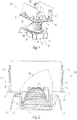
- FIGS 1 and 2 show first in two different views, the essential components of an inventively designed, generally provided with the reference numeral 100 downlights.
- this downlight 100 is intended to be mounted in a - here square and not shown - installation opening a suspended ceiling. The light is then emitted to the bottom of an area to be illuminated.
- Such downlights are used in many ways, both for the illumination of work areas as well as in rooms of public buildings such as museums and the like.
- first a first element is permanently and firmly connected to the ceiling and all other components can be detachably mounted on this first fastened element.
- a permanently connected to the ceiling element is a so-called.
- Mounting frame or mounting frame 50 is used, which is adapted in terms of its shape and size to the mounting opening of the ceiling. In the present case, it is assumed that the mounting opening of the ceiling is made square, which is why the mounting frame 50 shown here has a square basic shape.
- the installation frame has an angled configuration with an outwardly directed circumferential flange 51 bearing against the underside of the ceiling in the mounted state and a peripheral web extending into or through the opening of the ceiling 52.
- the circumferential flange 51 serves to compensate for any irregularities in the ceiling installation opening or to laminate. It limits on its inside the actual installation opening, in which then the light carrier described in more detail later is used. Often, this flange 51 is - at least partially - plastered after attachment to the ceiling, so that a particularly inconspicuous transition between the ceiling and the elements of the lamp is achieved.
- the mounting frame 50 can be carried out either in one piece, which is particularly suitable for smaller dimensions of the frame, as well as consist of several separate profile parts, which are assembled to the frame-like construction or form the frame shape in a mounted state on the ceiling.
- This modular construction of the frame 50 is particularly suitable if the system is to be flexible in order to arrange a desired number of downlights next to one another.
- the mounting frame 50 also need not necessarily have the outwardly facing flange portion which bears against the underside of the ceiling, but may also be designed in the form of a flush-mounted version such that it has only a slightly inwardly projecting horizontal web, which in turn limited the installation opening.
- the fastening of such a mounting frame 50 on the ceiling can be done in many ways, for example. Screw are known, which would be conceivable in the present case.
- special locking elements 55 are provided, which are arranged on opposite sides of the mounting frame 50. These locking elements 55 are esp. By height adjustable, outwardly pivotable tabs formed, which initially in the in FIG. 1 illustrated configuration are vertically aligned downward so that they can reach through the ceiling mounting opening when inserting the mounting frame 50 to the ceiling. Subsequently, these locking elements 55 are pivoted outwardly and depressed by means of a special operating mechanism or by hand, so that they come into abutment against the top of the suspended ceiling.
- the ceiling is then so clamped between the locking elements 55 on the one hand and the outwardly projecting flange portion 51 of the mounting frame 50 on the other hand, so that the mounting frame 50 is firmly connected to the ceiling.
- Such measures are already known from earlier downlights or other recessed ceiling luminaires, which is why this will not be discussed further below.
- the attachment of the frame to the ceiling could of course be done in other ways.
- the luminaire head 30 includes a light source 31, for example in the form of an LED, whose light is emitted by means of a downwardly directed cup-shaped reflector 32.
- the heat generated during the operation of the light sources 31 heat is using a heat sink 33 emitted to the ambient air, which - according to the representations - extends to the top and is arranged in the mounted state within the intermediate area between suspended ceiling and raw ceiling.
- the power supply of the light source 31 can be effected by means of a separate control and power supply unit or a correspondingly integrated unit.
- the lamp head 30 itself can therefore be designed in different ways. For releasable attachment to the mounting frame 50, this is held by a so-called.
- Light carrier 10 which is designed according to the invention in the manner described in more detail below.
- the lamp head 30 is rotatable relative to the light carrier 10 and additionally also pivotably arranged thereon, in order to form a so-called gimbal lamp, which allows almost any alignment of the light output.
- a rigid connection between the lamp head 30 and light carrier 10 would be conceivable or the light carrier 10 could be an integral part of the lamp head 30.
- the invention is therefore not limited to the illustrated embodiment of the lamp head 30. Instead, this can be configured in various ways and connected in a suitable manner with the light carrier 10.
- an embodiment with a rectangular or square Lichtabstrahl Scheme would be conceivable, in which case the recess in the main surface then has a square shape and, for example. the reflector of - in this case, then not rotatable - lamp head is adjusted accordingly.
- the size of the recess in the main surface of the light carrier and thus the size of the Lichtabstrahl Schemes the lamp head can be varied.
- An advantage of the solution according to the invention consists in the fact that the light carrier can be combined with differently designed lighting heads and for this only a corresponding adjustment of the main surface of the light carrier is required.
- the present invention now relates in particular to the manner in which the light carrier 10 can be detachably fastened to the mounting frame 50.
- different solutions are known from the prior art, which are each associated with certain disadvantages.
- the solution according to the invention now opens the possibility to attach the light carrier 10 in a simple and fast manner to the mounting frame 50 and - if required - also to solve this again, where both steps can possibly also be done without tools.
- the light carrier 10 is initially characterized by its basic shape, which corresponds to the sectional view of FIG. 2 as well as the views of FIGS. 4 to 6 C-type is executed. That is, the light carrier 10 initially has a main surface provided with the reference numeral 11, which serves the arrangement of the lamp head 30. Since, as already mentioned, an adjustability of the lamp head 30 should be made possible in the present case, it is provided that this main surface 11 has a circular recess 12 with a peripheral edge region 13, which serves a rotatable mounting of the lamp head 30. On both sides of this recess 12, two short, upwardly oriented tabs or webs 14 are provided, which increase the stability of the light carrier 10 in the region of the main surface 11.
- the light carrier 10 is preferably made of plastic, but could also be formed of a different material, such as sheet metal.
- flanks 20 responsible for the actual attachment of the light carrier 10 to the mounting frame 50 are two arranged on both sides of the main surface 11 flanks 20, which are directed downward and relative to the vertical (it is assumed here that the main surface is oriented horizontally) to the outside pointing angle ⁇ from about 10 ° to 20 °, preferably from about 15 ° occupy (s. Fig. 6 ).
- These flanks 20 have a certain flexibility with respect to the main surface 11, such that they can be pressed inwards, in order - as described below - to allow insertion and removal in or out of the mounting frame 15.
- An attachment of the light carrier 10 to the mounting frame 50 is achieved by means of locking means, which are realized by two locking lugs 22, which are each formed at the lower ends of the flanks 20.
- These latching lugs 22 are designed such that they cooperate with corresponding latching recesses 60 of the mounting frame 50, said latching recesses 60 are executed on the inner sides of two upwardly directed webs 61 of the mounting frame 50. These webs 61 with the recesses 60 may in particular the representation of FIG. 3 be removed.
- the locking lugs 22 each have approximately centrally a recess or a slot or an opening 23 which extends into the lower region of the flank 20 and in the mounted state of the light carrier 10 allow the insertion of a tool, for example.
- a small slotted screwdriver This can be introduced from the bottom through the opening 23 until it is supported on the webs 61 of the mounting frame 50.
- the locking lugs 20 can be levered or pushed out of the corresponding openings 60 and thus the connection between the mounting frame 50 and light carrier 10 can be solved.
- the locking lugs 22 should protrude as perpendicularly from the side surfaces of the flanks 20 to ensure a reliable locking connection between mounting frame 50 and light carrier 10, the locking lugs 22 are not able themselves when inserting the light carrier 10 in the mounting frame 50 for a corresponding deflection of the flanks 20 to care. Instead, the detents 22 would rather catch on the inner edge of the flange portion 51 of the mounting frame 50.
- each guide elements in the form of ribs 25 are provided, which extend from the top to the lower edge of the respective edge 20 and are designed such that they are 10 when inserting the light carrier slide along the inner edge of the flange portion 51 of the mounting frame 50, thereby causing an inward migration or bending of the associated edge 20. That is to say, these so-called shoehorn ribs 25 provide for the required emigration of the flank 20 towards the inside, so that the detent nose 22 can slide past the lower edge of the mounting frame 50 and subsequently engage in the associated recess 60. As a result, the assembly is facilitated and it is additionally prevented that the locking lugs 20 lead to damage such as scratches or the like on the mounting frame 50.
- the light carrier 10 with the lamp head 30 located thereon in the representations of FIGS. 7 and 8 shown, esp. in FIG. 8 It can be seen in what way then engage the locking lugs 22 in the associated recess 60 of the mounting frame 50. In fact, with only two locking lugs 22 located on opposite sides, a sufficiently reliable mounting of the light carrier 10 can be achieved, so that no further or additional securing measures are required.
- a support lip or support rib 53 which in particular in the enlarged view of FIG. 8 is recognizable.
- This support rib 53 is slightly behind inside projecting portion 54 of the flange portion 51 of the mounting frame 50, on which the light carrier 20 rests, formed and forms an upwardly projecting small web.
- this stop is increased by the weight of the light carrier 10 and the associated lamp head 30, as this presses the lower edges of the flanks 20 in the support area or receiving area between the recess 60 and support rib 53 and thus prevents an independent release of the locking connection.
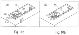
- the solution according to the invention is also characterized in that the assembly and disassembly is simplified by the special manner of interaction between mounting frame 50 and light carrier 10. This is recognizable on the basis of the following Figures 9 and 10 which on the one hand show the insertion of the light carrier 10 in a mounting frame 50 and on the other hand, the subsequent removal. It is assumed in the present case that now several similar light carrier 10 are to be arranged together on a mounting frame 50, wherein the figures each show the assembly or disassembly of the respective first light carrier.
- the preferred procedure for mounting the light carrier 10 is that this - according to the representation of FIG. 9a - First, slightly obliquely attached to the already attached to the ceiling 150 mounting frame 50, so that the locking lug 22 of one of the two flanks 20 engages already in the corresponding recess 60 of the mounting frame 50. Subsequently, the opposite region of the light carrier 10 is pushed or pivoted upwards, wherein with the aid of the ribs 25 described above, the deflection of the flank 20 to the inside is facilitated or supported. Once the inner edge of the mounting frame 50 has been passed through the corresponding locking lug 22, this can then engage in the opposite recess 60, which is illustrated by a clicking sound. In this way, it is thus immediately apparent to the installer that the light carrier 10 has been correctly secured to the mounting frame 50.
- the release of the locking connection is shown schematically in the Figures 10a and 10b represented, in the present case, a tool 80 in the form of a screwdriver is used. This is introduced through the aforementioned opening 23 in the region between the latching recess 60 and locking lug 22, and then pivoted so that the latching connection is released. By a subsequent pivoting then the light carrier 10 also on the opposite side the locking connection dissolved and removed. Alternatively, however, it would also be conceivable to move the light carrier 10 transversely in a first step, with the result that in turn the latching connection between light carrier 10 and mounting frame 50 is released on one side. Also in this case can then be finally removed by subsequent pivoting the light carrier 10.
Landscapes
- Engineering & Computer Science (AREA)
- General Engineering & Computer Science (AREA)
- Non-Portable Lighting Devices Or Systems Thereof (AREA)
Claims (7)
- Plafonnier (100) avec un cadre de montage (50) à monter dans la zone d'une ouverture de montage au plafond, ainsi qu'un support de lumière (10) à fixer sur le cadre de montage (50) avec une tête de luminaire (30) se trouvant dessus,
où le support de lumière (10) est conçu par un élément essentiellement en forme de C avec une surface principale (11) ainsi que deux flancs angulaires (20) disposés sur des côtés opposés l'un à l'autre de la surface principale (11) et où les flancs (20) du support de lumière (10) sont conçus flexibles et pour venir s'encliqueter avec le cadre de montage (50), où
les flancs (20) du support de lumière (10) présentent respectivement sur leurs extrémités opposées à la surface principale (10), des moyens d'encliquetage orientés vers l'extérieur pour venir s'encliqueter avec le cadre de montage (50), où il s'agit dans le cas des moyens d'encliquetage d'ergots d'encliquetage (22) respectifs, et où le cadre de montage (50) présente des ouvertures d'encliquetage (60) complémentaires des ergots d'encliquetage (22),
caractérisé en ce
que les ergots d'encliquetage (22) présentent respectivement une ouverture (23) ou un évidement, qui permettent de libérer la liaison par encliquetage respective au moyen d'un outil (80). - Plafonnier selon la revendication 1,
caractérisé en ce
que, sur les surfaces orientées vers l'extérieur des flancs (20) du support de lumière (10), des éléments de guidage sont formés, qui provoquent une déviation du flanc correspondant (20) lors de l'introduction du support de lumière (10) dans le cadre de montage (50). - Plafonnier selon la revendication 2
caractérisé en ce
que, dans le cas des éléments de guidage, il s'agit de deux nervures (25) qui s'étendent des deux côtés des moyens d'encliquetage. - Plafonnier selon l'une des revendications précédentes, caractérisé en ce
que le cadre de montage (50) présente des moyens de support - de préférence sous la forme de nervures de support (53) - au niveau d'une zone d'appui pour le support de lumière (10), par le biais desquelles il est possible d'empêcher une déviation des flancs flexibles (20) vers l'intérieur. - Plafonnier selon l'une des revendications précédentes, caractérisé en ce
que le support de lumière (10) est composé de matière plastique. - Plafonnier selon l'une des revendications précédentes, caractérisé en ce
que la tête de luminaire (30) est disposée de manière réglable, notamment rotative, sur le support de lumière (10). - Plafonnier selon l'une des revendications précédentes, caractérisé en ce
que le cadre de montage (50) est conçu pour le support de plusieurs supports de lumière (10).
Applications Claiming Priority (2)
| Application Number | Priority Date | Filing Date | Title |
|---|---|---|---|
| DE202014105019.1U DE202014105019U1 (de) | 2014-10-21 | 2014-10-21 | Downlight |
| PCT/EP2015/074336 WO2016062754A1 (fr) | 2014-10-21 | 2015-10-21 | Plafonnier à spots lumineux |
Publications (2)
| Publication Number | Publication Date |
|---|---|
| EP3209934A1 EP3209934A1 (fr) | 2017-08-30 |
| EP3209934B1 true EP3209934B1 (fr) | 2018-10-03 |
Family
ID=54337761
Family Applications (1)
| Application Number | Title | Priority Date | Filing Date |
|---|---|---|---|
| EP15784029.9A Active EP3209934B1 (fr) | 2014-10-21 | 2015-10-21 | Plafonnier à spots lumineux |
Country Status (4)
| Country | Link |
|---|---|
| US (1) | US10168034B2 (fr) |
| EP (1) | EP3209934B1 (fr) |
| DE (1) | DE202014105019U1 (fr) |
| WO (1) | WO2016062754A1 (fr) |
Families Citing this family (2)
| Publication number | Priority date | Publication date | Assignee | Title |
|---|---|---|---|---|
| DE102017104142A1 (de) | 2017-02-28 | 2018-08-30 | Osram Gmbh | Einbauleuchte, insbesondere für "Sealed For Life"-Leuchteneinsätze |
| US11619241B2 (en) | 2021-07-09 | 2023-04-04 | Home Depot Product Authority, Llc | Ventilation fan installation system |
Family Cites Families (8)
| Publication number | Priority date | Publication date | Assignee | Title |
|---|---|---|---|---|
| FR2646699B1 (fr) | 1989-05-02 | 1991-07-26 | Philips Eclairage | Luminaire destine a etre monte dans un faux-plafond |
| US5390090A (en) * | 1991-12-09 | 1995-02-14 | Nau; Larry J. | Ground supported lamp |
| US6364511B1 (en) * | 2000-03-31 | 2002-04-02 | Amp Plus, Inc. | Universal adapter bracket and ornamental trim assembly using same for in-ceiling recessed light fixtures |
| DE10145499A1 (de) * | 2001-09-14 | 2003-04-03 | Zumtobel Staff Gmbh & Co Kg | Lichtkanalsystem |
| DE202008003338U1 (de) | 2008-01-23 | 2008-05-21 | Rd System-Leuchten Ag | Montagesystem für Funktionsmodule |
| DE102008005779A1 (de) * | 2008-01-23 | 2009-08-13 | Rd System-Leuchten Ag | Montagesystem für Funktionsmodule |
| DE202009016736U1 (de) * | 2009-10-13 | 2011-02-24 | Erco Gmbh | Modul-Bausystem für eine Einbauleuchte |
| DE202013102148U1 (de) * | 2012-12-10 | 2014-03-12 | Zumtobel Lighting Gmbh | Einbauleuchte |
-
2014
- 2014-10-21 DE DE202014105019.1U patent/DE202014105019U1/de not_active Expired - Lifetime
-
2015
- 2015-10-21 WO PCT/EP2015/074336 patent/WO2016062754A1/fr active Application Filing
- 2015-10-21 US US15/502,873 patent/US10168034B2/en active Active
- 2015-10-21 EP EP15784029.9A patent/EP3209934B1/fr active Active
Non-Patent Citations (1)
| Title |
|---|
| None * |
Also Published As
| Publication number | Publication date |
|---|---|
| US20170227196A1 (en) | 2017-08-10 |
| WO2016062754A1 (fr) | 2016-04-28 |
| DE202014105019U1 (de) | 2016-01-25 |
| US10168034B2 (en) | 2019-01-01 |
| EP3209934A1 (fr) | 2017-08-30 |
Similar Documents
| Publication | Publication Date | Title |
|---|---|---|
| DE102005032265B4 (de) | Rastbefestigung von Leuchtenbauteilen | |
| DE102014213468B4 (de) | Leuchte für eine Rasterdecke, Verfahren zum Demontieren einer Leuchte, sowie Demontagewerkzeug | |
| DE3147510A1 (de) | Abgehaengte decke mit integriertem beleuchtungskoerper, beleuchtungskoerper und verfahren zum bau einer abgehaengten decke mit beleuchtungskoerper | |
| EP2886946A1 (fr) | Support pour un composant de fonctionnement d'un éclairage | |
| EP0732540A2 (fr) | Armature lumineuse encastrée avec des moyens pour sa fixation dans le corps de logement | |
| EP3209933B1 (fr) | Plafonnier à spots lumineux | |
| EP2929234B1 (fr) | Luminaire encastre dans un plan | |
| EP3209934B1 (fr) | Plafonnier à spots lumineux | |
| AT14156U1 (de) | System zur Montage einer Deckenanbauleuchte an einer Decke | |
| EP2215402B1 (fr) | Dispositif de mise à niveau pour monter une lampe de manière réglable en hauteur | |
| EP0813027A2 (fr) | Lampe montable sur un rail de support | |
| EP1267119B1 (fr) | Lamp en saillie | |
| EP1504216B1 (fr) | Paralume pourvu de reflecteurs lateraux a double paroi | |
| DE10234459B4 (de) | Verbindungselement zum Befestigen eines optischen Leuchtenbauteils an einer Leuchte und Leuchte | |
| DE202009013561U1 (de) | Leuchtensystem für den Deckeneinbau | |
| EP2208192B1 (fr) | Appareil d'éclairage pour pictogramme | |
| WO2018158328A1 (fr) | Luminaire encastré comportant un cadre de montage et une unité d'émission lumineuse | |
| DE10118783B4 (de) | Montagesystem für ein Leuchtenbauteil sowie Leuchte mit einem solchen Montagesystem | |
| WO2017054024A1 (fr) | Dispositif de maintien avec profilé porteur et élément de maintien pour le profilé porteur | |
| DE202016103572U1 (de) | Modul für eine Leuchte, insbesondere für eine Lichtbandleuchte | |
| DE102022126249A1 (de) | Befestigungssystem für eine Leuchte, Befestigungselement sowie eine Leuchte | |
| WO2000060281A1 (fr) | Dispositif destine a la fixation d'un objet a un plafond | |
| DE102018117269A1 (de) | Befestigungssystem, insbesondere für Leuchten | |
| AT14513U1 (de) | Deckeneinbauleuchte sowie Gehäuse für eine Deckeneinbauleuchte | |
| EP0961078A2 (fr) | Luminaire encastré |
Legal Events
| Date | Code | Title | Description |
|---|---|---|---|
| STAA | Information on the status of an ep patent application or granted ep patent |
Free format text: STATUS: THE INTERNATIONAL PUBLICATION HAS BEEN MADE |
|
| PUAI | Public reference made under article 153(3) epc to a published international application that has entered the european phase |
Free format text: ORIGINAL CODE: 0009012 |
|
| STAA | Information on the status of an ep patent application or granted ep patent |
Free format text: STATUS: REQUEST FOR EXAMINATION WAS MADE |
|
| 17P | Request for examination filed |
Effective date: 20170420 |
|
| AK | Designated contracting states |
Kind code of ref document: A1 Designated state(s): AL AT BE BG CH CY CZ DE DK EE ES FI FR GB GR HR HU IE IS IT LI LT LU LV MC MK MT NL NO PL PT RO RS SE SI SK SM TR |
|
| AX | Request for extension of the european patent |
Extension state: BA ME |
|
| DAV | Request for validation of the european patent (deleted) | ||
| DAX | Request for extension of the european patent (deleted) | ||
| GRAP | Despatch of communication of intention to grant a patent |
Free format text: ORIGINAL CODE: EPIDOSNIGR1 |
|
| STAA | Information on the status of an ep patent application or granted ep patent |
Free format text: STATUS: GRANT OF PATENT IS INTENDED |
|
| INTG | Intention to grant announced |
Effective date: 20180430 |
|
| GRAS | Grant fee paid |
Free format text: ORIGINAL CODE: EPIDOSNIGR3 |
|
| GRAA | (expected) grant |
Free format text: ORIGINAL CODE: 0009210 |
|
| STAA | Information on the status of an ep patent application or granted ep patent |
Free format text: STATUS: THE PATENT HAS BEEN GRANTED |
|
| AK | Designated contracting states |
Kind code of ref document: B1 Designated state(s): AL AT BE BG CH CY CZ DE DK EE ES FI FR GB GR HR HU IE IS IT LI LT LU LV MC MK MT NL NO PL PT RO RS SE SI SK SM TR |
|
| REG | Reference to a national code |
Ref country code: GB Ref legal event code: FG4D Free format text: NOT ENGLISH |
|
| REG | Reference to a national code |
Ref country code: CH Ref legal event code: EP Ref country code: AT Ref legal event code: REF Ref document number: 1049002 Country of ref document: AT Kind code of ref document: T Effective date: 20181015 |
|
| REG | Reference to a national code |
Ref country code: FR Ref legal event code: PLFP Year of fee payment: 4 |
|
| REG | Reference to a national code |
Ref country code: CH Ref legal event code: NV Representative=s name: VENI GMBH, CH Ref country code: DE Ref legal event code: R096 Ref document number: 502015006261 Country of ref document: DE Ref country code: IE Ref legal event code: FG4D Free format text: LANGUAGE OF EP DOCUMENT: GERMAN |
|
| REG | Reference to a national code |
Ref country code: NL Ref legal event code: MP Effective date: 20181003 |
|
| REG | Reference to a national code |
Ref country code: LT Ref legal event code: MG4D |
|
| PG25 | Lapsed in a contracting state [announced via postgrant information from national office to epo] |
Ref country code: NL Free format text: LAPSE BECAUSE OF FAILURE TO SUBMIT A TRANSLATION OF THE DESCRIPTION OR TO PAY THE FEE WITHIN THE PRESCRIBED TIME-LIMIT Effective date: 20181003 |
|
| PG25 | Lapsed in a contracting state [announced via postgrant information from national office to epo] |
Ref country code: HR Free format text: LAPSE BECAUSE OF FAILURE TO SUBMIT A TRANSLATION OF THE DESCRIPTION OR TO PAY THE FEE WITHIN THE PRESCRIBED TIME-LIMIT Effective date: 20181003 Ref country code: NO Free format text: LAPSE BECAUSE OF FAILURE TO SUBMIT A TRANSLATION OF THE DESCRIPTION OR TO PAY THE FEE WITHIN THE PRESCRIBED TIME-LIMIT Effective date: 20190103 Ref country code: LV Free format text: LAPSE BECAUSE OF FAILURE TO SUBMIT A TRANSLATION OF THE DESCRIPTION OR TO PAY THE FEE WITHIN THE PRESCRIBED TIME-LIMIT Effective date: 20181003 Ref country code: BG Free format text: LAPSE BECAUSE OF FAILURE TO SUBMIT A TRANSLATION OF THE DESCRIPTION OR TO PAY THE FEE WITHIN THE PRESCRIBED TIME-LIMIT Effective date: 20190103 Ref country code: PL Free format text: LAPSE BECAUSE OF FAILURE TO SUBMIT A TRANSLATION OF THE DESCRIPTION OR TO PAY THE FEE WITHIN THE PRESCRIBED TIME-LIMIT Effective date: 20181003 Ref country code: LT Free format text: LAPSE BECAUSE OF FAILURE TO SUBMIT A TRANSLATION OF THE DESCRIPTION OR TO PAY THE FEE WITHIN THE PRESCRIBED TIME-LIMIT Effective date: 20181003 Ref country code: ES Free format text: LAPSE BECAUSE OF FAILURE TO SUBMIT A TRANSLATION OF THE DESCRIPTION OR TO PAY THE FEE WITHIN THE PRESCRIBED TIME-LIMIT Effective date: 20181003 Ref country code: CZ Free format text: LAPSE BECAUSE OF FAILURE TO SUBMIT A TRANSLATION OF THE DESCRIPTION OR TO PAY THE FEE WITHIN THE PRESCRIBED TIME-LIMIT Effective date: 20181003 Ref country code: IS Free format text: LAPSE BECAUSE OF FAILURE TO SUBMIT A TRANSLATION OF THE DESCRIPTION OR TO PAY THE FEE WITHIN THE PRESCRIBED TIME-LIMIT Effective date: 20190203 Ref country code: FI Free format text: LAPSE BECAUSE OF FAILURE TO SUBMIT A TRANSLATION OF THE DESCRIPTION OR TO PAY THE FEE WITHIN THE PRESCRIBED TIME-LIMIT Effective date: 20181003 |
|
| PG25 | Lapsed in a contracting state [announced via postgrant information from national office to epo] |
Ref country code: GR Free format text: LAPSE BECAUSE OF FAILURE TO SUBMIT A TRANSLATION OF THE DESCRIPTION OR TO PAY THE FEE WITHIN THE PRESCRIBED TIME-LIMIT Effective date: 20190104 Ref country code: SE Free format text: LAPSE BECAUSE OF FAILURE TO SUBMIT A TRANSLATION OF THE DESCRIPTION OR TO PAY THE FEE WITHIN THE PRESCRIBED TIME-LIMIT Effective date: 20181003 Ref country code: RS Free format text: LAPSE BECAUSE OF FAILURE TO SUBMIT A TRANSLATION OF THE DESCRIPTION OR TO PAY THE FEE WITHIN THE PRESCRIBED TIME-LIMIT Effective date: 20181003 Ref country code: AL Free format text: LAPSE BECAUSE OF FAILURE TO SUBMIT A TRANSLATION OF THE DESCRIPTION OR TO PAY THE FEE WITHIN THE PRESCRIBED TIME-LIMIT Effective date: 20181003 Ref country code: PT Free format text: LAPSE BECAUSE OF FAILURE TO SUBMIT A TRANSLATION OF THE DESCRIPTION OR TO PAY THE FEE WITHIN THE PRESCRIBED TIME-LIMIT Effective date: 20190203 |
|
| REG | Reference to a national code |
Ref country code: BE Ref legal event code: MM Effective date: 20181031 |
|
| PG25 | Lapsed in a contracting state [announced via postgrant information from national office to epo] |
Ref country code: LU Free format text: LAPSE BECAUSE OF NON-PAYMENT OF DUE FEES Effective date: 20181021 |
|
| REG | Reference to a national code |
Ref country code: DE Ref legal event code: R097 Ref document number: 502015006261 Country of ref document: DE |
|
| REG | Reference to a national code |
Ref country code: IE Ref legal event code: MM4A |
|
| PG25 | Lapsed in a contracting state [announced via postgrant information from national office to epo] |
Ref country code: IT Free format text: LAPSE BECAUSE OF FAILURE TO SUBMIT A TRANSLATION OF THE DESCRIPTION OR TO PAY THE FEE WITHIN THE PRESCRIBED TIME-LIMIT Effective date: 20181003 Ref country code: DK Free format text: LAPSE BECAUSE OF FAILURE TO SUBMIT A TRANSLATION OF THE DESCRIPTION OR TO PAY THE FEE WITHIN THE PRESCRIBED TIME-LIMIT Effective date: 20181003 |
|
| PLBE | No opposition filed within time limit |
Free format text: ORIGINAL CODE: 0009261 |
|
| STAA | Information on the status of an ep patent application or granted ep patent |
Free format text: STATUS: NO OPPOSITION FILED WITHIN TIME LIMIT |
|
| PG25 | Lapsed in a contracting state [announced via postgrant information from national office to epo] |
Ref country code: MC Free format text: LAPSE BECAUSE OF FAILURE TO SUBMIT A TRANSLATION OF THE DESCRIPTION OR TO PAY THE FEE WITHIN THE PRESCRIBED TIME-LIMIT Effective date: 20181003 Ref country code: RO Free format text: LAPSE BECAUSE OF FAILURE TO SUBMIT A TRANSLATION OF THE DESCRIPTION OR TO PAY THE FEE WITHIN THE PRESCRIBED TIME-LIMIT Effective date: 20181003 Ref country code: SK Free format text: LAPSE BECAUSE OF FAILURE TO SUBMIT A TRANSLATION OF THE DESCRIPTION OR TO PAY THE FEE WITHIN THE PRESCRIBED TIME-LIMIT Effective date: 20181003 Ref country code: EE Free format text: LAPSE BECAUSE OF FAILURE TO SUBMIT A TRANSLATION OF THE DESCRIPTION OR TO PAY THE FEE WITHIN THE PRESCRIBED TIME-LIMIT Effective date: 20181003 Ref country code: BE Free format text: LAPSE BECAUSE OF NON-PAYMENT OF DUE FEES Effective date: 20181031 Ref country code: SM Free format text: LAPSE BECAUSE OF FAILURE TO SUBMIT A TRANSLATION OF THE DESCRIPTION OR TO PAY THE FEE WITHIN THE PRESCRIBED TIME-LIMIT Effective date: 20181003 |
|
| 26N | No opposition filed |
Effective date: 20190704 |
|
| PG25 | Lapsed in a contracting state [announced via postgrant information from national office to epo] |
Ref country code: IE Free format text: LAPSE BECAUSE OF NON-PAYMENT OF DUE FEES Effective date: 20181021 Ref country code: SI Free format text: LAPSE BECAUSE OF FAILURE TO SUBMIT A TRANSLATION OF THE DESCRIPTION OR TO PAY THE FEE WITHIN THE PRESCRIBED TIME-LIMIT Effective date: 20181003 |
|
| PG25 | Lapsed in a contracting state [announced via postgrant information from national office to epo] |
Ref country code: MT Free format text: LAPSE BECAUSE OF FAILURE TO SUBMIT A TRANSLATION OF THE DESCRIPTION OR TO PAY THE FEE WITHIN THE PRESCRIBED TIME-LIMIT Effective date: 20181003 |
|
| PG25 | Lapsed in a contracting state [announced via postgrant information from national office to epo] |
Ref country code: TR Free format text: LAPSE BECAUSE OF FAILURE TO SUBMIT A TRANSLATION OF THE DESCRIPTION OR TO PAY THE FEE WITHIN THE PRESCRIBED TIME-LIMIT Effective date: 20181003 |
|
| PG25 | Lapsed in a contracting state [announced via postgrant information from national office to epo] |
Ref country code: CY Free format text: LAPSE BECAUSE OF FAILURE TO SUBMIT A TRANSLATION OF THE DESCRIPTION OR TO PAY THE FEE WITHIN THE PRESCRIBED TIME-LIMIT Effective date: 20181003 Ref country code: MK Free format text: LAPSE BECAUSE OF NON-PAYMENT OF DUE FEES Effective date: 20181003 Ref country code: HU Free format text: LAPSE BECAUSE OF FAILURE TO SUBMIT A TRANSLATION OF THE DESCRIPTION OR TO PAY THE FEE WITHIN THE PRESCRIBED TIME-LIMIT; INVALID AB INITIO Effective date: 20151021 |
|
| REG | Reference to a national code |
Ref country code: GB Ref legal event code: 732E Free format text: REGISTERED BETWEEN 20210930 AND 20211006 |
|
| REG | Reference to a national code |
Ref country code: AT Ref legal event code: MM01 Ref document number: 1049002 Country of ref document: AT Kind code of ref document: T Effective date: 20201021 |
|
| PG25 | Lapsed in a contracting state [announced via postgrant information from national office to epo] |
Ref country code: AT Free format text: LAPSE BECAUSE OF NON-PAYMENT OF DUE FEES Effective date: 20201021 |
|
| PGFP | Annual fee paid to national office [announced via postgrant information from national office to epo] |
Ref country code: FR Payment date: 20221024 Year of fee payment: 8 |
|
| P01 | Opt-out of the competence of the unified patent court (upc) registered |
Effective date: 20230530 |
|
| REG | Reference to a national code |
Ref country code: DE Ref legal event code: R084 Ref document number: 502015006261 Country of ref document: DE Ref country code: DE Ref legal event code: R086 Ref document number: 502015006261 Country of ref document: DE |
|
| PGFP | Annual fee paid to national office [announced via postgrant information from national office to epo] |
Ref country code: GB Payment date: 20231024 Year of fee payment: 9 |
|
| PGFP | Annual fee paid to national office [announced via postgrant information from national office to epo] |
Ref country code: DE Payment date: 20231027 Year of fee payment: 9 Ref country code: CH Payment date: 20231102 Year of fee payment: 9 |
|
| PG25 | Lapsed in a contracting state [announced via postgrant information from national office to epo] |
Ref country code: FR Free format text: LAPSE BECAUSE OF NON-PAYMENT OF DUE FEES Effective date: 20231031 |