EP3209727B1 - Plaque de mousse coalescées latéralement - Google Patents
Plaque de mousse coalescées latéralement Download PDFInfo
- Publication number
- EP3209727B1 EP3209727B1 EP15851762.3A EP15851762A EP3209727B1 EP 3209727 B1 EP3209727 B1 EP 3209727B1 EP 15851762 A EP15851762 A EP 15851762A EP 3209727 B1 EP3209727 B1 EP 3209727B1
- Authority
- EP
- European Patent Office
- Prior art keywords
- foam slab
- slab
- foam
- unitary
- phase
- Prior art date
- Legal status (The legal status is an assumption and is not a legal conclusion. Google has not performed a legal analysis and makes no representation as to the accuracy of the status listed.)
- Active
Links
- 239000006260 foam Substances 0.000 title claims description 390
- 239000002131 composite material Substances 0.000 claims description 138
- 239000002344 surface layer Substances 0.000 claims description 40
- 229920000728 polyester Polymers 0.000 claims description 39
- 239000010410 layer Substances 0.000 claims description 27
- 239000000758 substrate Substances 0.000 claims description 25
- -1 polypropylene Polymers 0.000 claims description 24
- 238000004581 coalescence Methods 0.000 claims description 10
- 239000006261 foam material Substances 0.000 claims description 9
- 229920000098 polyolefin Polymers 0.000 claims description 7
- 239000004743 Polypropylene Substances 0.000 claims description 6
- 229920001155 polypropylene Polymers 0.000 claims description 6
- 239000002356 single layer Substances 0.000 claims description 6
- 229920006254 polymer film Polymers 0.000 claims description 5
- 238000007711 solidification Methods 0.000 claims description 4
- 230000008023 solidification Effects 0.000 claims description 4
- 239000000203 mixture Substances 0.000 description 59
- 239000000463 material Substances 0.000 description 30
- 238000005187 foaming Methods 0.000 description 27
- 238000000034 method Methods 0.000 description 17
- 210000004027 cell Anatomy 0.000 description 15
- 125000006850 spacer group Chemical group 0.000 description 11
- 239000004604 Blowing Agent Substances 0.000 description 10
- 229920000139 polyethylene terephthalate Polymers 0.000 description 10
- 239000005020 polyethylene terephthalate Substances 0.000 description 10
- 229920002799 BoPET Polymers 0.000 description 7
- LYCAIKOWRPUZTN-UHFFFAOYSA-N Ethylene glycol Chemical compound OCCO LYCAIKOWRPUZTN-UHFFFAOYSA-N 0.000 description 7
- 239000002666 chemical blowing agent Substances 0.000 description 7
- 239000004970 Chain extender Substances 0.000 description 6
- 238000013461 design Methods 0.000 description 6
- 230000009977 dual effect Effects 0.000 description 6
- 150000002148 esters Chemical class 0.000 description 6
- 238000001125 extrusion Methods 0.000 description 6
- 239000000654 additive Substances 0.000 description 5
- 230000008859 change Effects 0.000 description 5
- 229920001577 copolymer Polymers 0.000 description 5
- 230000008569 process Effects 0.000 description 5
- 210000002421 cell wall Anatomy 0.000 description 4
- 230000006870 function Effects 0.000 description 4
- 239000000178 monomer Substances 0.000 description 4
- 229920005644 polyethylene terephthalate glycol copolymer Polymers 0.000 description 4
- 230000003014 reinforcing effect Effects 0.000 description 4
- 239000002253 acid Substances 0.000 description 3
- 229910052799 carbon Inorganic materials 0.000 description 3
- 238000004891 communication Methods 0.000 description 3
- 239000012530 fluid Substances 0.000 description 3
- 239000007789 gas Substances 0.000 description 3
- 239000003365 glass fiber Substances 0.000 description 3
- 229920001519 homopolymer Polymers 0.000 description 3
- 239000002184 metal Substances 0.000 description 3
- 229910052751 metal Inorganic materials 0.000 description 3
- 229920006267 polyester film Polymers 0.000 description 3
- 239000000126 substance Substances 0.000 description 3
- 150000003504 terephthalic acids Chemical class 0.000 description 3
- 229920001169 thermoplastic Polymers 0.000 description 3
- 239000004416 thermosoftening plastic Substances 0.000 description 3
- VLDPXPPHXDGHEW-UHFFFAOYSA-N 1-chloro-2-dichlorophosphoryloxybenzene Chemical compound ClC1=CC=CC=C1OP(Cl)(Cl)=O VLDPXPPHXDGHEW-UHFFFAOYSA-N 0.000 description 2
- XKRFYHLGVUSROY-UHFFFAOYSA-N Argon Chemical compound [Ar] XKRFYHLGVUSROY-UHFFFAOYSA-N 0.000 description 2
- IJGRMHOSHXDMSA-UHFFFAOYSA-N Atomic nitrogen Chemical compound N#N IJGRMHOSHXDMSA-UHFFFAOYSA-N 0.000 description 2
- CURLTUGMZLYLDI-UHFFFAOYSA-N Carbon dioxide Chemical compound O=C=O CURLTUGMZLYLDI-UHFFFAOYSA-N 0.000 description 2
- IMNFDUFMRHMDMM-UHFFFAOYSA-N N-Heptane Chemical class CCCCCCC IMNFDUFMRHMDMM-UHFFFAOYSA-N 0.000 description 2
- VYPSYNLAJGMNEJ-UHFFFAOYSA-N Silicium dioxide Chemical compound O=[Si]=O VYPSYNLAJGMNEJ-UHFFFAOYSA-N 0.000 description 2
- CDBYLPFSWZWCQE-UHFFFAOYSA-L Sodium Carbonate Chemical compound [Na+].[Na+].[O-]C([O-])=O CDBYLPFSWZWCQE-UHFFFAOYSA-L 0.000 description 2
- UIIMBOGNXHQVGW-UHFFFAOYSA-M Sodium bicarbonate Chemical compound [Na+].OC([O-])=O UIIMBOGNXHQVGW-UHFFFAOYSA-M 0.000 description 2
- KKEYFWRCBNTPAC-UHFFFAOYSA-N Terephthalic acid Chemical compound OC(=O)C1=CC=C(C(O)=O)C=C1 KKEYFWRCBNTPAC-UHFFFAOYSA-N 0.000 description 2
- GWEVSGVZZGPLCZ-UHFFFAOYSA-N Titan oxide Chemical compound O=[Ti]=O GWEVSGVZZGPLCZ-UHFFFAOYSA-N 0.000 description 2
- 125000001931 aliphatic group Chemical group 0.000 description 2
- 125000003118 aryl group Chemical group 0.000 description 2
- 230000008901 benefit Effects 0.000 description 2
- WERYXYBDKMZEQL-UHFFFAOYSA-N butane-1,4-diol Chemical compound OCCCCO WERYXYBDKMZEQL-UHFFFAOYSA-N 0.000 description 2
- 238000012512 characterization method Methods 0.000 description 2
- 238000006243 chemical reaction Methods 0.000 description 2
- 239000004744 fabric Substances 0.000 description 2
- 239000002657 fibrous material Substances 0.000 description 2
- 239000011888 foil Substances 0.000 description 2
- 239000011521 glass Substances 0.000 description 2
- 125000002887 hydroxy group Chemical group [H]O* 0.000 description 2
- QQVIHTHCMHWDBS-UHFFFAOYSA-N isophthalic acid Chemical compound OC(=O)C1=CC=CC(C(O)=O)=C1 QQVIHTHCMHWDBS-UHFFFAOYSA-N 0.000 description 2
- 238000003475 lamination Methods 0.000 description 2
- 239000007788 liquid Substances 0.000 description 2
- 239000012764 mineral filler Substances 0.000 description 2
- 238000012544 monitoring process Methods 0.000 description 2
- 229920000620 organic polymer Polymers 0.000 description 2
- 229920001707 polybutylene terephthalate Polymers 0.000 description 2
- 229920000642 polymer Polymers 0.000 description 2
- 239000011347 resin Substances 0.000 description 2
- 229920005989 resin Polymers 0.000 description 2
- 238000003892 spreading Methods 0.000 description 2
- 230000007480 spreading Effects 0.000 description 2
- 238000012360 testing method Methods 0.000 description 2
- DNIAPMSPPWPWGF-VKHMYHEASA-N (+)-propylene glycol Chemical compound C[C@H](O)CO DNIAPMSPPWPWGF-VKHMYHEASA-N 0.000 description 1
- YPFDHNVEDLHUCE-UHFFFAOYSA-N 1,3-propanediol Substances OCCCO YPFDHNVEDLHUCE-UHFFFAOYSA-N 0.000 description 1
- 229940035437 1,3-propanediol Drugs 0.000 description 1
- NMYFVWYGKGVPIW-UHFFFAOYSA-N 3,7-dioxabicyclo[7.2.2]trideca-1(11),9,12-triene-2,8-dione Chemical compound O=C1OCCCOC(=O)C2=CC=C1C=C2 NMYFVWYGKGVPIW-UHFFFAOYSA-N 0.000 description 1
- NBOCQTNZUPTTEI-UHFFFAOYSA-N 4-[4-(hydrazinesulfonyl)phenoxy]benzenesulfonohydrazide Chemical compound C1=CC(S(=O)(=O)NN)=CC=C1OC1=CC=C(S(=O)(=O)NN)C=C1 NBOCQTNZUPTTEI-UHFFFAOYSA-N 0.000 description 1
- MARUHZGHZWCEQU-UHFFFAOYSA-N 5-phenyl-2h-tetrazole Chemical compound C1=CC=CC=C1C1=NNN=N1 MARUHZGHZWCEQU-UHFFFAOYSA-N 0.000 description 1
- 239000004156 Azodicarbonamide Substances 0.000 description 1
- 229920001634 Copolyester Polymers 0.000 description 1
- 239000004593 Epoxy Substances 0.000 description 1
- 239000004606 Fillers/Extenders Substances 0.000 description 1
- 241000308582 Gonostoma elongatum Species 0.000 description 1
- 239000004609 Impact Modifier Substances 0.000 description 1
- 239000006057 Non-nutritive feed additive Substances 0.000 description 1
- OFBQJSOFQDEBGM-UHFFFAOYSA-N Pentane Chemical class CCCCC OFBQJSOFQDEBGM-UHFFFAOYSA-N 0.000 description 1
- LGRFSURHDFAFJT-UHFFFAOYSA-N Phthalic anhydride Natural products C1=CC=C2C(=O)OC(=O)C2=C1 LGRFSURHDFAFJT-UHFFFAOYSA-N 0.000 description 1
- 239000004952 Polyamide Substances 0.000 description 1
- 239000004698 Polyethylene Substances 0.000 description 1
- 239000004793 Polystyrene Substances 0.000 description 1
- ATUOYWHBWRKTHZ-UHFFFAOYSA-N Propane Chemical class CCC ATUOYWHBWRKTHZ-UHFFFAOYSA-N 0.000 description 1
- 238000000333 X-ray scattering Methods 0.000 description 1
- 239000006096 absorbing agent Substances 0.000 description 1
- 150000007513 acids Chemical class 0.000 description 1
- 239000000853 adhesive Substances 0.000 description 1
- 230000001070 adhesive effect Effects 0.000 description 1
- 229920003232 aliphatic polyester Polymers 0.000 description 1
- 239000003513 alkali Substances 0.000 description 1
- 150000001412 amines Chemical class 0.000 description 1
- 150000008064 anhydrides Chemical class 0.000 description 1
- 239000003963 antioxidant agent Substances 0.000 description 1
- 239000002216 antistatic agent Substances 0.000 description 1
- 229910052786 argon Inorganic materials 0.000 description 1
- 238000000149 argon plasma sintering Methods 0.000 description 1
- 150000001541 aziridines Chemical class 0.000 description 1
- XOZUGNYVDXMRKW-AATRIKPKSA-N azodicarbonamide Chemical compound NC(=O)\N=N\C(N)=O XOZUGNYVDXMRKW-AATRIKPKSA-N 0.000 description 1
- 235000019399 azodicarbonamide Nutrition 0.000 description 1
- 230000004888 barrier function Effects 0.000 description 1
- 239000011324 bead Substances 0.000 description 1
- 238000005452 bending Methods 0.000 description 1
- 235000013844 butane Nutrition 0.000 description 1
- JHIWVOJDXOSYLW-UHFFFAOYSA-N butyl 2,2-difluorocyclopropane-1-carboxylate Chemical compound CCCCOC(=O)C1CC1(F)F JHIWVOJDXOSYLW-UHFFFAOYSA-N 0.000 description 1
- 239000001569 carbon dioxide Substances 0.000 description 1
- 229910002092 carbon dioxide Inorganic materials 0.000 description 1
- 150000004649 carbonic acid derivatives Chemical class 0.000 description 1
- 238000005266 casting Methods 0.000 description 1
- 230000010261 cell growth Effects 0.000 description 1
- 238000000701 chemical imaging Methods 0.000 description 1
- 239000004927 clay Substances 0.000 description 1
- 229910052570 clay Inorganic materials 0.000 description 1
- 238000004140 cleaning Methods 0.000 description 1
- 239000003086 colorant Substances 0.000 description 1
- 150000001875 compounds Chemical class 0.000 description 1
- 230000006835 compression Effects 0.000 description 1
- 238000007906 compression Methods 0.000 description 1
- 238000002425 crystallisation Methods 0.000 description 1
- 230000008025 crystallization Effects 0.000 description 1
- 238000005520 cutting process Methods 0.000 description 1
- 150000004985 diamines Chemical class 0.000 description 1
- 150000001991 dicarboxylic acids Chemical class 0.000 description 1
- 150000005690 diesters Chemical class 0.000 description 1
- 150000002009 diols Chemical class 0.000 description 1
- 238000001493 electron microscopy Methods 0.000 description 1
- 150000002118 epoxides Chemical class 0.000 description 1
- 230000008020 evaporation Effects 0.000 description 1
- 238000001704 evaporation Methods 0.000 description 1
- 239000000835 fiber Substances 0.000 description 1
- 239000011152 fibreglass Substances 0.000 description 1
- 239000003063 flame retardant Substances 0.000 description 1
- 239000004088 foaming agent Substances 0.000 description 1
- 230000009477 glass transition Effects 0.000 description 1
- 150000002334 glycols Chemical class 0.000 description 1
- 239000001307 helium Substances 0.000 description 1
- 229910052734 helium Inorganic materials 0.000 description 1
- SWQJXJOGLNCZEY-UHFFFAOYSA-N helium atom Chemical compound [He] SWQJXJOGLNCZEY-UHFFFAOYSA-N 0.000 description 1
- 229930195733 hydrocarbon Natural products 0.000 description 1
- 150000002430 hydrocarbons Chemical class 0.000 description 1
- 230000003301 hydrolyzing effect Effects 0.000 description 1
- WGCNASOHLSPBMP-UHFFFAOYSA-N hydroxyacetaldehyde Natural products OCC=O WGCNASOHLSPBMP-UHFFFAOYSA-N 0.000 description 1
- 238000007373 indentation Methods 0.000 description 1
- 238000007689 inspection Methods 0.000 description 1
- 238000009413 insulation Methods 0.000 description 1
- 238000010030 laminating Methods 0.000 description 1
- 238000011031 large-scale manufacturing process Methods 0.000 description 1
- 239000004611 light stabiliser Substances 0.000 description 1
- 238000003754 machining Methods 0.000 description 1
- FPYJFEHAWHCUMM-UHFFFAOYSA-N maleic anhydride Chemical compound O=C1OC(=O)C=C1 FPYJFEHAWHCUMM-UHFFFAOYSA-N 0.000 description 1
- 238000005259 measurement Methods 0.000 description 1
- 230000007246 mechanism Effects 0.000 description 1
- 239000000155 melt Substances 0.000 description 1
- 230000008018 melting Effects 0.000 description 1
- 238000002844 melting Methods 0.000 description 1
- 239000004005 microsphere Substances 0.000 description 1
- 239000011490 mineral wool Substances 0.000 description 1
- 239000003607 modifier Substances 0.000 description 1
- IJDNQMDRQITEOD-UHFFFAOYSA-N n-butane Chemical class CCCC IJDNQMDRQITEOD-UHFFFAOYSA-N 0.000 description 1
- 239000002105 nanoparticle Substances 0.000 description 1
- 239000002071 nanotube Substances 0.000 description 1
- KYTZHLUVELPASH-UHFFFAOYSA-N naphthalene-1,2-dicarboxylic acid Chemical compound C1=CC=CC2=C(C(O)=O)C(C(=O)O)=CC=C21 KYTZHLUVELPASH-UHFFFAOYSA-N 0.000 description 1
- 238000001956 neutron scattering Methods 0.000 description 1
- 229910052757 nitrogen Inorganic materials 0.000 description 1
- 239000002667 nucleating agent Substances 0.000 description 1
- 230000003287 optical effect Effects 0.000 description 1
- 238000000399 optical microscopy Methods 0.000 description 1
- 238000004806 packaging method and process Methods 0.000 description 1
- 239000002245 particle Substances 0.000 description 1
- 239000008188 pellet Substances 0.000 description 1
- 239000000049 pigment Substances 0.000 description 1
- 229920002647 polyamide Polymers 0.000 description 1
- 229920001748 polybutylene Polymers 0.000 description 1
- 229920000515 polycarbonate Polymers 0.000 description 1
- 239000004417 polycarbonate Substances 0.000 description 1
- 238000012643 polycondensation polymerization Methods 0.000 description 1
- 229920000573 polyethylene Polymers 0.000 description 1
- 229920000306 polymethylpentene Polymers 0.000 description 1
- 239000011116 polymethylpentene Substances 0.000 description 1
- 229920002223 polystyrene Polymers 0.000 description 1
- 229920000166 polytrimethylene carbonate Polymers 0.000 description 1
- 229920002635 polyurethane Polymers 0.000 description 1
- 239000004814 polyurethane Substances 0.000 description 1
- 235000013849 propane Nutrition 0.000 description 1
- 238000002310 reflectometry Methods 0.000 description 1
- 239000012763 reinforcing filler Substances 0.000 description 1
- 229920006126 semicrystalline polymer Polymers 0.000 description 1
- 238000000926 separation method Methods 0.000 description 1
- 239000000377 silicon dioxide Substances 0.000 description 1
- 239000012748 slip agent Substances 0.000 description 1
- 229910000030 sodium bicarbonate Inorganic materials 0.000 description 1
- 235000017557 sodium bicarbonate Nutrition 0.000 description 1
- 229910000029 sodium carbonate Inorganic materials 0.000 description 1
- 239000007787 solid Substances 0.000 description 1
- 239000003381 stabilizer Substances 0.000 description 1
- 229910001220 stainless steel Inorganic materials 0.000 description 1
- 239000010935 stainless steel Substances 0.000 description 1
- 239000000454 talc Substances 0.000 description 1
- 229910052623 talc Inorganic materials 0.000 description 1
- 238000012956 testing procedure Methods 0.000 description 1
- 230000000007 visual effect Effects 0.000 description 1
- 238000011179 visual inspection Methods 0.000 description 1
- 239000002759 woven fabric Substances 0.000 description 1
Images
Classifications
-
- B—PERFORMING OPERATIONS; TRANSPORTING
- B29—WORKING OF PLASTICS; WORKING OF SUBSTANCES IN A PLASTIC STATE IN GENERAL
- B29C—SHAPING OR JOINING OF PLASTICS; SHAPING OF MATERIAL IN A PLASTIC STATE, NOT OTHERWISE PROVIDED FOR; AFTER-TREATMENT OF THE SHAPED PRODUCTS, e.g. REPAIRING
- B29C44/00—Shaping by internal pressure generated in the material, e.g. swelling or foaming ; Producing porous or cellular expanded plastics articles
- B29C44/34—Auxiliary operations
- B29C44/36—Feeding the material to be shaped
- B29C44/46—Feeding the material to be shaped into an open space or onto moving surfaces, i.e. to make articles of indefinite length
- B29C44/468—Feeding the material to be shaped into an open space or onto moving surfaces, i.e. to make articles of indefinite length in a plurality of parallel streams which unite during the foaming
-
- B—PERFORMING OPERATIONS; TRANSPORTING
- B29—WORKING OF PLASTICS; WORKING OF SUBSTANCES IN A PLASTIC STATE IN GENERAL
- B29C—SHAPING OR JOINING OF PLASTICS; SHAPING OF MATERIAL IN A PLASTIC STATE, NOT OTHERWISE PROVIDED FOR; AFTER-TREATMENT OF THE SHAPED PRODUCTS, e.g. REPAIRING
- B29C48/00—Extrusion moulding, i.e. expressing the moulding material through a die or nozzle which imparts the desired form; Apparatus therefor
- B29C48/03—Extrusion moulding, i.e. expressing the moulding material through a die or nozzle which imparts the desired form; Apparatus therefor characterised by the shape of the extruded material at extrusion
- B29C48/07—Flat, e.g. panels
-
- B—PERFORMING OPERATIONS; TRANSPORTING
- B32—LAYERED PRODUCTS
- B32B—LAYERED PRODUCTS, i.e. PRODUCTS BUILT-UP OF STRATA OF FLAT OR NON-FLAT, e.g. CELLULAR OR HONEYCOMB, FORM
- B32B15/00—Layered products comprising a layer of metal
- B32B15/02—Layer formed of wires, e.g. mesh
-
- B—PERFORMING OPERATIONS; TRANSPORTING
- B32—LAYERED PRODUCTS
- B32B—LAYERED PRODUCTS, i.e. PRODUCTS BUILT-UP OF STRATA OF FLAT OR NON-FLAT, e.g. CELLULAR OR HONEYCOMB, FORM
- B32B15/00—Layered products comprising a layer of metal
- B32B15/04—Layered products comprising a layer of metal comprising metal as the main or only constituent of a layer, which is next to another layer of the same or of a different material
- B32B15/046—Layered products comprising a layer of metal comprising metal as the main or only constituent of a layer, which is next to another layer of the same or of a different material of foam
-
- B—PERFORMING OPERATIONS; TRANSPORTING
- B32—LAYERED PRODUCTS
- B32B—LAYERED PRODUCTS, i.e. PRODUCTS BUILT-UP OF STRATA OF FLAT OR NON-FLAT, e.g. CELLULAR OR HONEYCOMB, FORM
- B32B27/00—Layered products comprising a layer of synthetic resin
- B32B27/06—Layered products comprising a layer of synthetic resin as the main or only constituent of a layer, which is next to another layer of the same or of a different material
- B32B27/065—Layered products comprising a layer of synthetic resin as the main or only constituent of a layer, which is next to another layer of the same or of a different material of foam
-
- B—PERFORMING OPERATIONS; TRANSPORTING
- B32—LAYERED PRODUCTS
- B32B—LAYERED PRODUCTS, i.e. PRODUCTS BUILT-UP OF STRATA OF FLAT OR NON-FLAT, e.g. CELLULAR OR HONEYCOMB, FORM
- B32B27/00—Layered products comprising a layer of synthetic resin
- B32B27/36—Layered products comprising a layer of synthetic resin comprising polyesters
-
- B—PERFORMING OPERATIONS; TRANSPORTING
- B32—LAYERED PRODUCTS
- B32B—LAYERED PRODUCTS, i.e. PRODUCTS BUILT-UP OF STRATA OF FLAT OR NON-FLAT, e.g. CELLULAR OR HONEYCOMB, FORM
- B32B5/00—Layered products characterised by the non- homogeneity or physical structure, i.e. comprising a fibrous, filamentary, particulate or foam layer; Layered products characterised by having a layer differing constitutionally or physically in different parts
- B32B5/02—Layered products characterised by the non- homogeneity or physical structure, i.e. comprising a fibrous, filamentary, particulate or foam layer; Layered products characterised by having a layer differing constitutionally or physically in different parts characterised by structural features of a fibrous or filamentary layer
-
- B—PERFORMING OPERATIONS; TRANSPORTING
- B32—LAYERED PRODUCTS
- B32B—LAYERED PRODUCTS, i.e. PRODUCTS BUILT-UP OF STRATA OF FLAT OR NON-FLAT, e.g. CELLULAR OR HONEYCOMB, FORM
- B32B5/00—Layered products characterised by the non- homogeneity or physical structure, i.e. comprising a fibrous, filamentary, particulate or foam layer; Layered products characterised by having a layer differing constitutionally or physically in different parts
- B32B5/18—Layered products characterised by the non- homogeneity or physical structure, i.e. comprising a fibrous, filamentary, particulate or foam layer; Layered products characterised by having a layer differing constitutionally or physically in different parts characterised by features of a layer of foamed material
-
- B—PERFORMING OPERATIONS; TRANSPORTING
- B32—LAYERED PRODUCTS
- B32B—LAYERED PRODUCTS, i.e. PRODUCTS BUILT-UP OF STRATA OF FLAT OR NON-FLAT, e.g. CELLULAR OR HONEYCOMB, FORM
- B32B5/00—Layered products characterised by the non- homogeneity or physical structure, i.e. comprising a fibrous, filamentary, particulate or foam layer; Layered products characterised by having a layer differing constitutionally or physically in different parts
- B32B5/22—Layered products characterised by the non- homogeneity or physical structure, i.e. comprising a fibrous, filamentary, particulate or foam layer; Layered products characterised by having a layer differing constitutionally or physically in different parts characterised by the presence of two or more layers which are next to each other and are fibrous, filamentary, formed of particles or foamed
- B32B5/24—Layered products characterised by the non- homogeneity or physical structure, i.e. comprising a fibrous, filamentary, particulate or foam layer; Layered products characterised by having a layer differing constitutionally or physically in different parts characterised by the presence of two or more layers which are next to each other and are fibrous, filamentary, formed of particles or foamed one layer being a fibrous or filamentary layer
- B32B5/245—Layered products characterised by the non- homogeneity or physical structure, i.e. comprising a fibrous, filamentary, particulate or foam layer; Layered products characterised by having a layer differing constitutionally or physically in different parts characterised by the presence of two or more layers which are next to each other and are fibrous, filamentary, formed of particles or foamed one layer being a fibrous or filamentary layer another layer next to it being a foam layer
-
- B—PERFORMING OPERATIONS; TRANSPORTING
- B32—LAYERED PRODUCTS
- B32B—LAYERED PRODUCTS, i.e. PRODUCTS BUILT-UP OF STRATA OF FLAT OR NON-FLAT, e.g. CELLULAR OR HONEYCOMB, FORM
- B32B7/00—Layered products characterised by the relation between layers; Layered products characterised by the relative orientation of features between layers, or by the relative values of a measurable parameter between layers, i.e. products comprising layers having different physical, chemical or physicochemical properties; Layered products characterised by the interconnection of layers
- B32B7/04—Interconnection of layers
- B32B7/12—Interconnection of layers using interposed adhesives or interposed materials with bonding properties
-
- E—FIXED CONSTRUCTIONS
- E04—BUILDING
- E04C—STRUCTURAL ELEMENTS; BUILDING MATERIALS
- E04C2/00—Building elements of relatively thin form for the construction of parts of buildings, e.g. sheet materials, slabs, or panels
- E04C2/02—Building elements of relatively thin form for the construction of parts of buildings, e.g. sheet materials, slabs, or panels characterised by specified materials
- E04C2/10—Building elements of relatively thin form for the construction of parts of buildings, e.g. sheet materials, slabs, or panels characterised by specified materials of wood, fibres, chips, vegetable stems, or the like; of plastics; of foamed products
- E04C2/20—Building elements of relatively thin form for the construction of parts of buildings, e.g. sheet materials, slabs, or panels characterised by specified materials of wood, fibres, chips, vegetable stems, or the like; of plastics; of foamed products of plastics
- E04C2/205—Building elements of relatively thin form for the construction of parts of buildings, e.g. sheet materials, slabs, or panels characterised by specified materials of wood, fibres, chips, vegetable stems, or the like; of plastics; of foamed products of plastics of foamed plastics, or of plastics and foamed plastics, optionally reinforced
-
- E—FIXED CONSTRUCTIONS
- E04—BUILDING
- E04C—STRUCTURAL ELEMENTS; BUILDING MATERIALS
- E04C2/00—Building elements of relatively thin form for the construction of parts of buildings, e.g. sheet materials, slabs, or panels
- E04C2/02—Building elements of relatively thin form for the construction of parts of buildings, e.g. sheet materials, slabs, or panels characterised by specified materials
- E04C2/26—Building elements of relatively thin form for the construction of parts of buildings, e.g. sheet materials, slabs, or panels characterised by specified materials composed of materials covered by two or more of groups E04C2/04, E04C2/08, E04C2/10 or of materials covered by one of these groups with a material not specified in one of the groups
- E04C2/284—Building elements of relatively thin form for the construction of parts of buildings, e.g. sheet materials, slabs, or panels characterised by specified materials composed of materials covered by two or more of groups E04C2/04, E04C2/08, E04C2/10 or of materials covered by one of these groups with a material not specified in one of the groups at least one of the materials being insulating
- E04C2/296—Building elements of relatively thin form for the construction of parts of buildings, e.g. sheet materials, slabs, or panels characterised by specified materials composed of materials covered by two or more of groups E04C2/04, E04C2/08, E04C2/10 or of materials covered by one of these groups with a material not specified in one of the groups at least one of the materials being insulating composed of insulating material and non-metallic or unspecified sheet-material
-
- B—PERFORMING OPERATIONS; TRANSPORTING
- B29—WORKING OF PLASTICS; WORKING OF SUBSTANCES IN A PLASTIC STATE IN GENERAL
- B29C—SHAPING OR JOINING OF PLASTICS; SHAPING OF MATERIAL IN A PLASTIC STATE, NOT OTHERWISE PROVIDED FOR; AFTER-TREATMENT OF THE SHAPED PRODUCTS, e.g. REPAIRING
- B29C44/00—Shaping by internal pressure generated in the material, e.g. swelling or foaming ; Producing porous or cellular expanded plastics articles
- B29C44/02—Shaping by internal pressure generated in the material, e.g. swelling or foaming ; Producing porous or cellular expanded plastics articles for articles of definite length, i.e. discrete articles
- B29C44/04—Shaping by internal pressure generated in the material, e.g. swelling or foaming ; Producing porous or cellular expanded plastics articles for articles of definite length, i.e. discrete articles consisting of at least two parts of chemically or physically different materials, e.g. having different densities
-
- B—PERFORMING OPERATIONS; TRANSPORTING
- B29—WORKING OF PLASTICS; WORKING OF SUBSTANCES IN A PLASTIC STATE IN GENERAL
- B29C—SHAPING OR JOINING OF PLASTICS; SHAPING OF MATERIAL IN A PLASTIC STATE, NOT OTHERWISE PROVIDED FOR; AFTER-TREATMENT OF THE SHAPED PRODUCTS, e.g. REPAIRING
- B29C44/00—Shaping by internal pressure generated in the material, e.g. swelling or foaming ; Producing porous or cellular expanded plastics articles
- B29C44/20—Shaping by internal pressure generated in the material, e.g. swelling or foaming ; Producing porous or cellular expanded plastics articles for articles of indefinite length
- B29C44/22—Shaping by internal pressure generated in the material, e.g. swelling or foaming ; Producing porous or cellular expanded plastics articles for articles of indefinite length consisting of at least two parts of chemically or physically different materials, e.g. having different densities
- B29C44/24—Making multilayered articles
-
- B—PERFORMING OPERATIONS; TRANSPORTING
- B32—LAYERED PRODUCTS
- B32B—LAYERED PRODUCTS, i.e. PRODUCTS BUILT-UP OF STRATA OF FLAT OR NON-FLAT, e.g. CELLULAR OR HONEYCOMB, FORM
- B32B2260/00—Layered product comprising an impregnated, embedded, or bonded layer wherein the layer comprises an impregnation, embedding, or binder material
- B32B2260/02—Composition of the impregnated, bonded or embedded layer
-
- B—PERFORMING OPERATIONS; TRANSPORTING
- B32—LAYERED PRODUCTS
- B32B—LAYERED PRODUCTS, i.e. PRODUCTS BUILT-UP OF STRATA OF FLAT OR NON-FLAT, e.g. CELLULAR OR HONEYCOMB, FORM
- B32B2260/00—Layered product comprising an impregnated, embedded, or bonded layer wherein the layer comprises an impregnation, embedding, or binder material
- B32B2260/04—Impregnation, embedding, or binder material
- B32B2260/046—Synthetic resin
-
- B—PERFORMING OPERATIONS; TRANSPORTING
- B32—LAYERED PRODUCTS
- B32B—LAYERED PRODUCTS, i.e. PRODUCTS BUILT-UP OF STRATA OF FLAT OR NON-FLAT, e.g. CELLULAR OR HONEYCOMB, FORM
- B32B2262/00—Composition or structural features of fibres which form a fibrous or filamentary layer or are present as additives
- B32B2262/10—Inorganic fibres
- B32B2262/101—Glass fibres
-
- B—PERFORMING OPERATIONS; TRANSPORTING
- B32—LAYERED PRODUCTS
- B32B—LAYERED PRODUCTS, i.e. PRODUCTS BUILT-UP OF STRATA OF FLAT OR NON-FLAT, e.g. CELLULAR OR HONEYCOMB, FORM
- B32B2262/00—Composition or structural features of fibres which form a fibrous or filamentary layer or are present as additives
- B32B2262/10—Inorganic fibres
- B32B2262/108—Rockwool fibres
-
- B—PERFORMING OPERATIONS; TRANSPORTING
- B32—LAYERED PRODUCTS
- B32B—LAYERED PRODUCTS, i.e. PRODUCTS BUILT-UP OF STRATA OF FLAT OR NON-FLAT, e.g. CELLULAR OR HONEYCOMB, FORM
- B32B2266/00—Composition of foam
- B32B2266/02—Organic
- B32B2266/0214—Materials belonging to B32B27/00
- B32B2266/025—Polyolefin
-
- B—PERFORMING OPERATIONS; TRANSPORTING
- B32—LAYERED PRODUCTS
- B32B—LAYERED PRODUCTS, i.e. PRODUCTS BUILT-UP OF STRATA OF FLAT OR NON-FLAT, e.g. CELLULAR OR HONEYCOMB, FORM
- B32B2266/00—Composition of foam
- B32B2266/02—Organic
- B32B2266/0214—Materials belonging to B32B27/00
- B32B2266/0264—Polyester
-
- B—PERFORMING OPERATIONS; TRANSPORTING
- B32—LAYERED PRODUCTS
- B32B—LAYERED PRODUCTS, i.e. PRODUCTS BUILT-UP OF STRATA OF FLAT OR NON-FLAT, e.g. CELLULAR OR HONEYCOMB, FORM
- B32B2307/00—Properties of the layers or laminate
- B32B2307/10—Properties of the layers or laminate having particular acoustical properties
- B32B2307/102—Insulating
-
- B—PERFORMING OPERATIONS; TRANSPORTING
- B32—LAYERED PRODUCTS
- B32B—LAYERED PRODUCTS, i.e. PRODUCTS BUILT-UP OF STRATA OF FLAT OR NON-FLAT, e.g. CELLULAR OR HONEYCOMB, FORM
- B32B2307/00—Properties of the layers or laminate
- B32B2307/30—Properties of the layers or laminate having particular thermal properties
- B32B2307/304—Insulating
-
- B—PERFORMING OPERATIONS; TRANSPORTING
- B32—LAYERED PRODUCTS
- B32B—LAYERED PRODUCTS, i.e. PRODUCTS BUILT-UP OF STRATA OF FLAT OR NON-FLAT, e.g. CELLULAR OR HONEYCOMB, FORM
- B32B2307/00—Properties of the layers or laminate
- B32B2307/50—Properties of the layers or laminate having particular mechanical properties
- B32B2307/514—Oriented
-
- C—CHEMISTRY; METALLURGY
- C08—ORGANIC MACROMOLECULAR COMPOUNDS; THEIR PREPARATION OR CHEMICAL WORKING-UP; COMPOSITIONS BASED THEREON
- C08L—COMPOSITIONS OF MACROMOLECULAR COMPOUNDS
- C08L23/00—Compositions of homopolymers or copolymers of unsaturated aliphatic hydrocarbons having only one carbon-to-carbon double bond; Compositions of derivatives of such polymers
- C08L23/02—Compositions of homopolymers or copolymers of unsaturated aliphatic hydrocarbons having only one carbon-to-carbon double bond; Compositions of derivatives of such polymers not modified by chemical after-treatment
- C08L23/10—Homopolymers or copolymers of propene
- C08L23/12—Polypropene
-
- C—CHEMISTRY; METALLURGY
- C08—ORGANIC MACROMOLECULAR COMPOUNDS; THEIR PREPARATION OR CHEMICAL WORKING-UP; COMPOSITIONS BASED THEREON
- C08L—COMPOSITIONS OF MACROMOLECULAR COMPOUNDS
- C08L67/00—Compositions of polyesters obtained by reactions forming a carboxylic ester link in the main chain; Compositions of derivatives of such polymers
-
- E—FIXED CONSTRUCTIONS
- E04—BUILDING
- E04B—GENERAL BUILDING CONSTRUCTIONS; WALLS, e.g. PARTITIONS; ROOFS; FLOORS; CEILINGS; INSULATION OR OTHER PROTECTION OF BUILDINGS
- E04B1/00—Constructions in general; Structures which are not restricted either to walls, e.g. partitions, or floors or ceilings or roofs
- E04B1/62—Insulation or other protection; Elements or use of specified material therefor
- E04B1/74—Heat, sound or noise insulation, absorption, or reflection; Other building methods affording favourable thermal or acoustical conditions, e.g. accumulating of heat within walls
- E04B1/76—Heat, sound or noise insulation, absorption, or reflection; Other building methods affording favourable thermal or acoustical conditions, e.g. accumulating of heat within walls specifically with respect to heat only
- E04B1/78—Heat insulating elements
- E04B1/80—Heat insulating elements slab-shaped
-
- E—FIXED CONSTRUCTIONS
- E04—BUILDING
- E04B—GENERAL BUILDING CONSTRUCTIONS; WALLS, e.g. PARTITIONS; ROOFS; FLOORS; CEILINGS; INSULATION OR OTHER PROTECTION OF BUILDINGS
- E04B1/00—Constructions in general; Structures which are not restricted either to walls, e.g. partitions, or floors or ceilings or roofs
- E04B1/62—Insulation or other protection; Elements or use of specified material therefor
- E04B1/74—Heat, sound or noise insulation, absorption, or reflection; Other building methods affording favourable thermal or acoustical conditions, e.g. accumulating of heat within walls
- E04B1/82—Heat, sound or noise insulation, absorption, or reflection; Other building methods affording favourable thermal or acoustical conditions, e.g. accumulating of heat within walls specifically with respect to sound only
- E04B1/84—Sound-absorbing elements
- E04B1/86—Sound-absorbing elements slab-shaped
-
- E—FIXED CONSTRUCTIONS
- E04—BUILDING
- E04B—GENERAL BUILDING CONSTRUCTIONS; WALLS, e.g. PARTITIONS; ROOFS; FLOORS; CEILINGS; INSULATION OR OTHER PROTECTION OF BUILDINGS
- E04B1/00—Constructions in general; Structures which are not restricted either to walls, e.g. partitions, or floors or ceilings or roofs
- E04B1/62—Insulation or other protection; Elements or use of specified material therefor
- E04B1/74—Heat, sound or noise insulation, absorption, or reflection; Other building methods affording favourable thermal or acoustical conditions, e.g. accumulating of heat within walls
- E04B1/88—Insulating elements for both heat and sound
- E04B1/90—Insulating elements for both heat and sound slab-shaped
-
- E—FIXED CONSTRUCTIONS
- E04—BUILDING
- E04C—STRUCTURAL ELEMENTS; BUILDING MATERIALS
- E04C2/00—Building elements of relatively thin form for the construction of parts of buildings, e.g. sheet materials, slabs, or panels
- E04C2/02—Building elements of relatively thin form for the construction of parts of buildings, e.g. sheet materials, slabs, or panels characterised by specified materials
- E04C2/26—Building elements of relatively thin form for the construction of parts of buildings, e.g. sheet materials, slabs, or panels characterised by specified materials composed of materials covered by two or more of groups E04C2/04, E04C2/08, E04C2/10 or of materials covered by one of these groups with a material not specified in one of the groups
- E04C2/284—Building elements of relatively thin form for the construction of parts of buildings, e.g. sheet materials, slabs, or panels characterised by specified materials composed of materials covered by two or more of groups E04C2/04, E04C2/08, E04C2/10 or of materials covered by one of these groups with a material not specified in one of the groups at least one of the materials being insulating
Definitions
- Foamed articles have found wide use in various applications, thermal or acoustic insulation, reinforcing layers and/or space-filling layers, and so on.
- the term "generally”, unless otherwise specifically defined, means that the property or attribute would be readily recognizable by a person of ordinary skill but without requiring a high degree of approximation (e.g., within +/- 20 % for quantifiable properties).
- the term “generally” means within clockwise or counterclockwise 30 degrees.
- the term “substantially”, unless otherwise specifically defined, means to a high degree of approximation (e.g., within +/- 10% for quantifiable properties).
- the term “substantially” means within clockwise or counterclockwise 10 degrees.
- a foaming die is meant an extrusion die that is configured to withstand the pressures present in the extrusion of a molten foamable flowstream.
- a foaming die comprises at least one die cavity configured to receive a molten flowstream e.g. from an extruder, and comprises a plurality of die orifices in fluid communication with the at least one die cavity.
- a molten foamable flowstream is meant a molten flowstream that comprises a molten foamable composition.
- a flowstream may be a multilayer flowstream in which e.g. only one layer of the flowstream comprises a foamable composition.
- a molten foamable composition a molten thermoplastic organic polymeric material that comprises a blowing agent (e.g., a physical blowing agent such as a gas or liquid; or, a chemical blowing agent that may chemically decompose e.g. at an elevated temperature, as discussed in detail later herein).
- a blowing agent e.g., a physical blowing agent such as a gas or liquid; or, a chemical blowing agent that may chemically decompose e.g. at an elevated temperature, as discussed in detail later herein.
- non-foamable is meant a molten composition that is at least essentially free of activatable blowing agent (e.g., so that a solidified product of the molten composition is a non-foam material with a relative density that is at least essentially equal to 1.0.)
- a foam an organic polymeric foam obtained by solidifying a molten foamable composition after the foaming process has proceeded to a desired extent.
- a foam slab is meant a foam entity with a length and a long axis, a lateral width and a lateral axis, and a thickness and a thickness axis, the three axes being orthogonal to each other and with the slab width being greater than the slab thickness.
- a foam slab is at least essentially compositionally uniform along the long axis of the slab.
- a foam slab admits the presence of densified (e.g. non-foam) material as a portion of the slab, as long as the densified material is made in the same operation as the foam portion of the slab, so that the portions collectively make up a unitary slab.
- unitary an entity (e.g., a foam slab) that is made in a single operation by the coalescence and solidification of molten flowstreams and that cannot be separated into parts without unacceptably damaging or destroying the entity.
- a unitary entity may be a composite entity, as long as all portions (e.g. layers, members, etc.) of the entity were made and brought together with each other in a single (e.g. coalescing/solidifying) operation so that the portions cannot be separated from each other are not removable from each other.
- a composite foam slab is meant a unitary foam slab that comprises, in addition to a major foam phase, at least one minor foam phase comprising a densified material.
- densified is used to distinguish a minor phase of a composite foam slab from a major, foam phase of the composite foam slab, and means that the minor phase exhibits a relative density that is at least about 15 % higher than that of the major, foam phase.
- densified is used for convenience of description and does not signify that a "densified” material cannot be a foam, nor does it require that a densified material must be a material that was first made at a lower density and then processed to increase its density.
- Relative density is a dimensionless parameter obtained by dividing the overall density of a material (e.g., a foam comprising air-filled cells) by the density of the substance that makes up the cell walls of the material. Relative density is sometimes referred to as reduced density.
- a material e.g., a foam comprising air-filled cells
- reduced density e.g. a polyester foam comprising a density of 0.5 g/cc and that comprises cell walls made of polyester that has a density of 1.35 g/cc
- the relative density is about 0.37.
- the relative density will be at least essentially equal to 1.0.
- a laterally-coalesced unitary organic polymeric foam slab 1100 As shown in exemplary embodiment in Fig. 1 .
- Foam slab 1100 exhibits a long axis (that corresponds to the extrusion direction of the flowstreams that coalesce to form the slab), a lateral axis (l s ) and a lateral width, and a thickness axis (t) and a thickness (which thickness by definition is less than the lateral width).
- laterally-coalesced is meant a unitary foam slab that is made primarily by lateral coalescence of molten extrudate flowstreams, as defined in detail below.
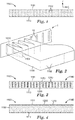
- Such a foam slab may be made e.g. by an exemplary apparatus and process as shown in Fig. 2 , which shows an exemplary unitary foam slab 1100 being produced by the (lateral) coalescing and solidification of molten foamable extrudate flowstreams 1010 that are emitted from orifices 10 of die 1.
- Fig. 2 shows an exemplary unitary foam slab 1100 being produced by the (lateral) coalescing and solidification of molten foamable extrudate flowstreams 1010 that are emitted from orifices 10 of die 1.
- foam slab 1100 in a laterally-aligned pattern, which orifices have a long axis oriented at least substantially along the height axis of the die, may result in foam slab 1100 being formed primarily by lateral coalescence of the molten foamable extrudate flowstreams. That is, foam slab 1100 may be formed primarily by way of the molten flowstreams expanding (due in large part to the foaming that commences upon the streams exiting the die orifices) and spreading laterally (right and left in the depiction of Fig. 2 ) so as to meet each other and coalesce.
- Such an orifice arrangement and the use thereof, and the resulting foam slab product will be distinguished from arrangements in which a foam slab is produced by emitting a molten foamable extrudate flowstream through a small number of slot orifices (e.g., one orifice) that have a long axis oriented along the lateral axis of a die (e.g., as in a conventional "coathanger" style die/orifice).
- slot orifices e.g., one orifice
- a long axis oriented along the lateral axis of a die e.g., as in a conventional "coathanger" style die/orifice.
- a laterally-coalesced foam slab may be identified e.g. by way of interfacial boundaries 1102 (shown in exemplary, idealized representation in Figs. 1 and 2 ) that demarcate locations at which the lateral surfaces of neighboring flowstreams met each other (such a meeting-point 1103 is shown in Fig. 2 ) and bonded to each other. It will be appreciated that due to e.g. lateral spreading that may occur in the foaming process, in some embodiments interfacial boundaries 1102 may be spaced further apart (across the lateral width (l s ) of foam slab 1100) than the spacing of die orifices 10 from which the adjacent flowstreams 1010 originated.
- Interfacial boundaries 1102 may be subtle, it being an advantage of the disclosures herein that the flowstreams may coalesce to form a unitary structure in such a complete manner that individual sections of the resulting foam slab coming from the different flowstreams may not easily be separable from each other, and might not be able to be distinguished by the simple expedient of cutting the slab in a cross-section and visually inspecting the exposed surface. (Such a laterally-coalesced foam slab thus possesses advantages over e.g. certain foam slabs described in U.S. Patent No. 3573152 to Wiley, individual sections of which may be readily separated from each other.) However, such interfacial boundaries may be identified, e.g.
- the aspect ratio e.g. of the cell dimensions along the thickness axis of the slab, relative to the cell dimensions along the lateral axis of the slab
- the local relative density may be used to identify interfacial boundaries.
- such interfacial boundaries may exhibit locally increased thickness of the cell walls (due e.g. to the collision and merging of laterally outwardmost cell walls of the two flowstreams).
- the degree to which the cells are open or closed may differ at such an interface.
- any suitable visual or optical method may be used for any such characterization. Such methods might rely on inspection (e.g. by visual inspection, optical microscopy, or electron microscopy). Or, methods such as e.g. reflectometry, hyperspectral imaging, light scattering, x-ray scattering, neutron scattering, etc., may be used.
- interfacial boundary may be identified e.g. by a change or discontinuity in e.g. melting temperature, glass transition temperature, tan delta, percent crystallinity, and so on.
- Interfacial boundaries may also be manifested e.g. as differences in indentation hardness in the region of a boundary, from that of regions far away (e.g. along the lateral axis of the foam) from a boundary.
- an interfacial boundary between a major, foam phase and a minor, densified phase may often be identified by e.g. a change in the relative density; the particular case of an interfacial boundary between a major, foam phase and a minor, non-foam phase may be readily identified by a change from the presence of cells to the absence of cells.
- interfacial boundaries of coalesced flowstreams may be identified by monitoring one or more properties of the foam as a foam slab is traversed.
- foam slab is traversed along the lateral axis (l s ) of the slab (i.e., along the width of the slab), rather than as the foam slab is traversed along the thickness axis (t) of the slab.
- interfacial boundaries will be primarily present as interfaces (e.g., at least substantially planar interfaces) 1102 that are at least generally aligned with the thickness axis (t) of the slab as shown in Fig.
- a laterally-coalesced foam slab is one in which multiple (e.g., at least four) identifiable interfacial boundaries are encountered in traversing the complete width of the foam slab along its lateral axis (l s ); and, in which at least about 80 % of the total area exhibited by all of the interfacial boundaries of the slab in combination is at least generally aligned with the thickness axis (t) of the foam slab.
- at least 6, 8, 10, 12, 14, 16, 20, 25, or 30 such interfacial boundaries may be present.
- interfacial boundaries may be present. (It will be appreciated that often, the number of interfacial boundaries may be (n-1), where n is the number of laterally-aligned die orifices 10 used to make the laterally-coalesced foam slab.)
- At least about 80, 85, 90, 95, 98, or at least essentially 100 %, of the total area of all of the interfacial boundaries of the slab are at least generally, at least substantially, or at least essentially, aligned with the thickness axis (t) of the foam slab.
- the exemplary representation of Fig. 1 shows a case in which 20 interfacial boundaries are present in foam slab 1100 and in which approximately 100 % of the total combined area of all of the interfacial boundaries is at least essentially aligned with the thickness axis (t) of the foam slab.
- such a slab will exhibit essentially no interfacial boundary area that is aligned with the lateral axis (l s ) of the slab, in contrast to e.g. the coalesced-strand foam slab shown in Fig. 4 of U.S. Patent No. 3573152 .
- At least about 60, 80, 90, or essentially 100 % (by number) of interfacial boundaries 1102 extend at least generally along thickness axis (t) of the foam slab, over at least about 80, 90, 95, 98, or at least essentially 100 % of the thickness of the foam slab.
- the unitary foam slab is a non-channeled foam slab.
- a non-channeled slab exhibits few or no internal macroscopic hollow (e.g., air-filled) elongate channels that extend along the long axis of the formed slab.
- Such a non-channeled slab is one that if cut in cross-section along a plane orthogonal to the long axis (extrusion direction) of the slab, will exhibit essentially no (that is, less than 1 % on average, measured as a percentage of the total area of the cross-sectionally exposed surface) such internal macroscopic hollow elongate channels.
- a laterally-coalesced unitary organic polymeric foam slab may be comprised of any suitable organic polymeric materials, as discussed in detail elsewhere herein.
- a foam slab may comprise a foam that is an open-cell foam, or a closed-cell foam; or, mixtures of the two cell types may be present.
- the relative density of a foam slab (or, of a major, foam phase of a slab, e.g. if the foam slab is a composite foam slab that includes a non-foam material as discussed elsewhere herein) may have any suitable value. In various embodiments, the relative density may be less than about 0.85, 0.8, 0.7, 0.6, 0.5, 0.4, 0.3, 0.2, or 0.1.
- the relative density may be greater than about 0.01, 0.05, 0.1, 0.15, 0.2, 0.3, or 0.4.
- the foam slab (or, again, a major, foam phase of a composite foam slab) may exhibit an average cell size in any suitable range.
- the average cell size may be at most about 4000 microns, 2000 microns, 1000 microns, 800 microns, 600 microns, 400 microns, 200 microns, 100 microns, 80 microns, 60 microns, 40 microns, 20 microns, or 10 microns.
- the average cell size may be at least about 1 micron, 5 microns, 10 microns, 15 microns, 20 microns, 25 microns, 30 microns, 40 microns, 50 microns, 100 microns, or 200 microns.
- a laterally-coalesced unitary organic polymeric foam slab may exhibit a shear modulus of at least about 1, 5, 10, 20, or 30 MPa. In various embodiments, a laterally-coalesced unitary organic polymeric foam slab may exhibit a compression modulus of at least about 1, 5, 10, 20, or 30 MPa. It will be appreciated that foam slabs of such properties may be well suited to serve as (e.g., at least semi-permanent) structural/reinforcing components, and are thus distinguished from e.g. organic polymeric foam slabs that are so weak as to be primarily used for e.g. space-filling or packaging applications.
- Foam slab 1100 may be of any desired composition, derived e.g. from any suitable molten foamable composition comprising any desired organic polymeric material in combination with any suitable blowing agent.
- Suitable organic polymers may be chosen from any thermoplastic (melt-extrudable) composition, encompassing e.g. one or more homopolymers, co-polymers (whether random, block, graft, and so on), mixtures or blends of various homopolymers or copolymers, and so on. In particular embodiments, any such polymers may be branched (e.g., in order to provide higher melt strength), if desired.
- Suitable organic polymers may be chosen from e.g.
- polyolefins polyesters, polyacrylics, polyamides, polycarbonates, polyurethanes, polystyrenes, and so on.
- Any suitable additives may be included as long as such additives do not unacceptably interfere with the foaming ability of the composition.
- one or more inorganic additives such as mineral fillers, reinforcing fillers, pigments may be used (e.g., talc, silica, clay, titania, glass fibers, glass bubbles, platelets, nanoparticles, nanotubes, and so on).
- additives might include antioxidants, ultraviolet absorbers, chain extenders, anti-static agents, hindered amine light stabilizers, hydrolytic stabilizers, nucleating agents, processing aids, flame retardants, coloring agents, slip agents, and so on. Any of these additives may be used in any desired combination.
- the organic polymeric material may be a polyolefinic material.
- suitable polyolefin materials includes e.g. polypropylene, polyethylene, polybutylene, poly(4-methyl-1-pentene), and copolymers and blends of any of these.
- the organic polymeric material may be a polyester material.
- polyester is meant any material in which at least about 70 % by weight of the organic polymeric material is a homopolymer and/or copolymer having ester linkages.
- ester-linkage polymer chains make up at least about 80 %, at least about 90 %, at least about 95 %, at least about 98 %, or at least 99.5 % of the weight of the material.
- the polyester is at least 70 % by weight polyethylene terephthalate, at least 80 % by weight polyethylene terephthalate, at least 90 % by weight polyethylene terephthalate, or at least 95 % by weight polyethylene terephthalate.
- the polyester material consists essentially of polyethylene terephthalate, which condition will be understood as not precluding the presence of a small amount (e.g., less than about 2.0 mole %) of monomeric units derived from glycols other than ethylene glycol.
- Suitable polyesters include e.g. those commonly made by condensation polymerization of hydroxyl-containing monomers and/or oligomers (e.g., chain extenders) with poly-acid-containing or poly-ester-containing monomers and/or oligomers (e.g., dicarboxylic acids or diesters such as terephthalic acid, isophthalic acid, naphthalene dicarboxylate, etc.).
- Such polyesters may be made from poly-acids, or from any ester-forming equivalents of such materials (e.g., from any materials that can be polymerized to ultimately provide a polyester).
- Such polyesters may be made from any suitable hydroxyl-containing chain extender or combination of extenders.
- chain extenders include for example the two-carbon diol, ethylene glycol (2G, when polymerized with terephthalic acids or esters yielding polyester “2GT”); the three-carbon diol, 1,3 propanediol (3G, when polymerized with terephthalic acids or esters yielding polyester “3GT”); and the four-carbon diol 1,4 butanediol (4G, when polymerized with terephthalic acids or esters yielding polyester “4GT”).
- 2GT polyethylene terephthalate or PET
- 3GT are trimethylene terephthalate (PTT) or polypropylene terephthalate (PPT) and for 4GT polybutylene terephthalate or PBT.
- Polyesters may be made e.g. from any suitable poly-acid-containing or poly-ester-containing monomers or oligomers or combination thereof.
- such monomers or oligomers may be selected such that the resulting polyester is an aromatic polyester; in other embodiments, they may be selected such that the resulting polyester is an aliphatic polyester.
- Blends of any of the above polyesters e.g., aliphatic with aromatic may be used, as can aliphatic/aromatic copolymers.
- polyesters that may be useful (not only for use in a foamable composition, but also in a densified, e.g. non-foamable, composition) are described in U. S. Patent Application Serial No. 14/363132 , entitled “Methods of Bonding Polyester Substrates", published on February 19, 2015 as U.S. Patent Application Publication No. 2015/0047774 .
- the foamable composition include a chain extender (e.g. in order to enhance the melt strength of the molten composition).
- anhydrides such as phthalic anhydride, maleic anhydride, or pyromellitic dianhydride (PMDA), and/or compounds such as certain aziridines, epoxides and diamines, are used for such purposes.
- PMDA pyromellitic dianhydride
- a molten foamable composition from which foam slab 1100 is derived may include any suitable blowing agent (sometimes referred to as a foaming agent), in any effective amount.
- blowing agents are often broadly categorized as physical blowing agents (meaning molecules that undergo a physical phase change, e.g. volatilization or evaporation, without any chemical reaction) or as chemical blowing agents (in which a chemical reaction typically occurs to liberate a gaseous or volatile molecule).
- Non-limiting examples of physical blowing agents include various gases (e.g., argon, helium, nitrogen, carbon dioxide, etc.).
- Further examples include volatilizable liquids, including hydrocarbons such as various propanes, butanes, pentanes, heptanes, and so on.
- Non-limiting examples of chemical blowing agents include e.g. azodicarbonamide, oxybis (benzene sulfonylhydrazide), phenyl tetrazole, and alkali carbonates comprising e.g., sodium carbonate and/or sodium bicarbonate).
- a laterally-coalesced unitary organic polymeric foam slab 1100 may consist essentially of an organic polymeric foam. That is, such a foam slab will be at least essentially uniformly made of a single monolayer of foam that extends uniformly throughout the length, width, and thickness of the slab (excepting interfacial boundaries as noted above), there being no minor phases (e.g., rails and/or sheet-like layers) of other materials present.
- This type of monolayer foam slab 1100 is depicted in exemplary embodiment in Fig. 1 .
- a laterally-coalesced unitary organic polymeric foam slab 1100 may be a unitary composite foam slab 1140, as depicted in exemplary embodiments in Figs. 3 and 4 .
- a composite foam slab by definition comprises at least one major organic polymeric foam phase 1150 and at least one minor, organic polymeric densified phase 1200.
- each phase, including the minor phase is a macroscopic phase (e.g., a rail as depicted in Fig. 3 , or a sheet-like surface layer as depicted in Fig. 4 ) that extends continuously along the long axis of the composite foam slab and is at least substantially aligned with the long axis of the slab.
- each minor phase has as second dimension that extends (e.g., along the thickness axis of the foam slab in the case of a rail, or along the lateral axis of the foam slab in the case of a sheet-like surface layer) a distance of at least about 2 mm, which distance is at least generally constant along the long axis of the slab.
- Such a macroscopic minor phase cannot be provided by microscopic entities such as particles (e.g., mineral fillers, glass beads, microspheres, impact modifiers and so on), whiskers, fibers or threads, and so on.
- microscopic entities such as particles (e.g., mineral fillers, glass beads, microspheres, impact modifiers and so on), whiskers, fibers or threads, and so on.
- such a minor phase be provided by the presence of different domains (e.g., lamellae, spherulites, etc.) that are well-known to occur on a microscopic scale in e.g. semicrystalline polymers. That is, while any such entities are permitted, and may be present, in a minor phase, the presence of such entities in and of themselves cannot provide a minor phase of a unitary composite foam slab as disclosed herein.
- such minor phases exclude any already-formed entity that is introduced into the molten extrudate flowstreams in a pre-existing (solid) form, such as any type of pre-existing member, rod, strand, filament, netting that is introduced into the midst of the molten extrudate flowstreams so that the flowstreams encapsulate the entity at least partially within the thus-formed foam slab.
- a pre-existing (solid) form such as any type of pre-existing member, rod, strand, filament, netting that is introduced into the midst of the molten extrudate flowstreams so that the flowstreams encapsulate the entity at least partially within the thus-formed foam slab.
- a densified, minor phase of a foam slab will exhibit a relative density that is at least about 15 % higher than the relative density of the major, foam phase of the slab.
- a densified, minor phase may be derived from a molten organic polymeric material that is similar or identical to that used to provide a major, foam phase of the foam slab, but that has a lower amount of blowing agent so as to provide a lessened degree of foaming.
- densified does not signify or require any particular absolute density but merely denotes a minor phase with a relative density that is at least about 15 % higher than that of the major, foam phase of a composite foam slab.
- a minor, densified phase may take the form of a non-foam phase with a relative density of at least essentially 1.0.
- a densified, minor phase may differ in chemical composition from the major, foam phase of the foam slab. In some embodiments such differences may be relatively minor, which may advantageously promote or enhance the ability of the compositions to intermingle and/or physically or chemically bond to each other during a coalescing process.
- the densified, minor phase and the major, foam phase may be melt-bondable with each other.
- a densified phase may have a relative density that is at least about 50 % higher, at least about 100 % higher (i.e., is twice as high), or is 3, 4, 8, 16, 32, or 64 times the relative density of the major, foam phase.
- a densified phase may have a relative density that is at most about 32, 16, 8, 4, or 2 times that of the major, foam phase. It is noted that the relative density of a non-foam (and non-porous in general) material will be at least essentially 1.0.
- a major, foam phase of a foam slab may make up at least about 40, 50, 60, 80, 90, 95, 98, or 99 volume percent of a composite foam slab. In further embodiments, the major, foam phase of a foam slab may make up at most about 99.5, 99, 97, 95, 90, 80, or 70 volume percent of a composite foam slab. In various embodiments, a minor, densified phase of a foam slab may make up at most about 60, 50, 40, 20, 10, 5, 2, 1, or 0.5 volume percent of a composite foam slab. (The terms major and minor are used for convenience of description to distinguish between a foam phase and a densified phase and do not necessarily require that the "major" phase must make up e.g. more than 50 volume percent of the composite foam slab.)
- the minor, densified phase of a foam slab may make up at least about 0.2, 0.5, 1.0, 3.0, 5, 10, 20, or 30 volume percent of a composite foam slab. (All such calculations are based on the nominal, macroscopic volumes of the major and minor phases.)
- a composite foam slab may comprise a major, foam phase in the form of a single, contiguous entity that is not interrupted by the presence of any intervening minor phase.
- the exemplary composite foam slab of Fig. 4 is an example of this type.
- a composite foam slab may comprise a major foam phase that is at least partially interrupted by an intervening minor phase.
- the exemplary embodiment of Fig. 3 is an example of this type.
- a major, foam phase may be present in the form of multiple entities, that are e.g. completely interrupted by an intervening minor phase.
- the entities of major, foam phase 1150 may nonetheless all be derived from the same molten composition and thus may all exhibit the same properties, e.g. relative density), if desired.
- a composite foam slab may comprise a minor, densified phase in the form of a single, contiguous entity that is not interrupted by the presence of any intervening major phase.
- the exemplary composite foam slab of Fig. 4 is an example of this type.
- a composite foam slab may comprise a minor phase that is at least partially interrupted by an intervening major, foam phase.
- the exemplary embodiment of Fig. 3 is an example of this type. Fig. 3 depicts an arrangement in which a minor phase 1200 is present as multiple discrete entities 1250. It is thus clear the term "phase" as used herein thus encompasses situations in which the phase is present as multiple discrete entities.
- the entities of the minor phase may nonetheless all be derived from the same molten composition and thus may all exhibit the same properties (e.g. relative density), if desired.
- a minor, densified phase of a unitary composite foam slab may be melt-bonded to the major, foam phase of the composite slab.
- a minor, densified phase, and a major, foam phase may both be comprised of polyester.
- a unitary foam slab 1100 that is a unitary composite foam slab 1140 may comprise a major, foam phase 1150, and a minor, densified phase 1200 that is in the form of a plurality of elongate members 1250 that are spaced apart, along a lateral axis of the foam slab, across at least 70 % of a width of the foam slab, wherein each elongate member extends continuously along the long axis of the composite foam slab.
- An exemplary design of this type is depicted in Fig. 3 .
- such elongate members may be spaced apart across at least about 80, 85, 90, or 95 % of the width of the composite foam slab.
- each minor-phase elongate member 1250 may comprise a relative density that is at least about two, four, six, or eight times the relative density of the major, foam phase 1150 of composite foam slab 1100.
- an elongate member may be in the form of an elongate rail 1250 that comprises a rail height that is at least substantially aligned with a thickness axis of the unitary composite foam slab and a rail width that is at least generally aligned with a lateral axis of the unitary composite foam slab.
- the rail height will be the end-to-end distance measured along the rail along the thickness axis of the slab, and will correspond to the second dimension (that has a value of at least about 2 mm) that was referred to in the definition of a minor phase.
- the rail height is greater than the rail thickness.
- the rail height may be at least about 1.5, 2, 4, 6, 8 or 10 times the rail thickness (with average rail height and rail thickness being used in the case of e.g. a rail that varies in thickness along the height of the rail).
- the rail height may be any suitable value relative to the thickness of the unitary composite foam slab. In various embodiments, the rail height may be at least about 20, 40, 60 80, 90, or 95 % of the thickness of the unitary composite foam slab. In further embodiments, the rail height may be at most about 100, 99, 98, 95, or 90 % of the thickness of the slab. Not all rails 1250 need be of the same, or even similar, rail height, although identical rails heights are shown in the exemplary embodiment of Fig. 3 . In some embodiments an elongate member (e.g. a rail) 1250 may be "buried" at at least one end of the rail (along the thickness axis of the slab).
- Fig. 3 shows an arrangement in which both ends of rails 1250 are buried ends, for all rails 1250.
- the major surfaces of the composite foam slab are at least substantially free of "print-through", which phenomenon is defined as a lump or bulge in a major foam surface, caused by the presence of an elongate member (e.g., a rail) that is buried beneath in the major foam surface in the area of the lump or bulge.
- Elongate members e.g. elongate rails
- the ordinary artisan will appreciate that, for example, such rails may serve as reinforcing rails that advantageously enhance the bending stiffness, rigidity, structural integrity, and so on, of a unitary foam slab.
- a unitary foam slab 1100 that is a unitary composite foam slab 1140 may comprise a major, foam phase 1150, and a minor, densified phase 1200 that is in the form of a minor, surface layer 1270 that is a sheet-like layer that provides a provides a major outer surface 1111 of the composite foam slab, as shown in exemplary embodiment in Fig. 4 . It will be appreciated that such a sheet-like surface layer 1270 will often extend continuously down the long axis of the foam slab 1140. Such a sheet-like surface layer can have any lateral width relative to the lateral width of major, foam phase 1150 that is desired. Fig.
- a surface layer 1270 may have a lateral width that is at least about 50, 60, 70, or, 90, or 95 % of the lateral width of major, foam phase 1150.
- a surface layer 1270 may have a lateral width that is at most about 100, 99, 98, 95, 90, 80, or 70 95 % of the lateral width of major, foam phase 1150. It may be convenient to provide a surface layer 1270 as a single entity that extends across at least essentially the entire lateral width of the thus-formed unitary composite foam slab, as in Fig. 4 .
- a sheet-like surface layer 1270 may have a thickness (e.g., an average thickness) that is less than about 25, 20, 15, 10, 5, 3, 2 or 1 % of the total thickness of the composite foam slab.
- a sheet-like surface layer 1270 may comprise a relative density that is at least about two, four, six, or eight times the relative density of the major, foam phase 1150 of composite foam slab 1100.
- a unitary composite foam slab with a minor, densified surface layer of this general type will comprise an interfacial boundary between the major, foam phase and the minor, densified phase.
- This interfacial boundary will be oriented at least generally along the lateral axis of the foam slab.
- the major, foam phase will still exhibit a sufficient number of interfacial boundaries that are at least generally aligned with the thickness axis (t) of the foam slab so that the composite foam slab is a laterally-coalesced foam slab as defined herein.
- a unitary composite foam slab 1140 has first and second minor-phase surface layers 1270, one on each side of a central major, foam phase 1150.
- a second such surface layer may have any of the above-described properties and attributes.
- a second such surface layer may have a composition and/or properties that are at least generally similar, at least substantially similar, or at least essentially the same as those of the first surface layer.
- a sheet-like surface layer or layers may serve any useful function in a unitary composite foam slab.
- a layer may serve as a tie layer that provides a foam slab with a major outer surface 1111 that is easier to bond to than is the (formerly) outermost surface of the major, foam layer 1150 itself.
- major, foam layer 1150 is comprised of polyester
- a minor-phase surface layer may be used that is e.g. glycol-modified polyester.
- Such a material may be easier to melt-bond e.g. a biaxially-oriented polyester film to, than it would be to bond such a film directly to a major surface of a polyester major foam layer 1150 itself.
- a sheet-like surface layer may (whether in addition to, or instead of, serving as a tie layer) provide a reinforcing or stiffening function.
- a unitary composite foam slab of the general type shown in Fig. 4 may provide a sandwich style foam composite in which two relatively thin surface layers of relative high density and thus e.g. inherently high stiffness (and which advantageously may be comprised of non-foam materials), outwardly sandwich an inner foam core of lower density.
- a sheet-like surface layer or layers 1270 may be derived from a molten composition that provides a higher barrier to passage of gases and/or vapors, than the molten composition from which is derived the major, foam phase 1150.
- the diffusional escape of the blowing agent from the growing cells of the incipient foam may be reduced from what it would be in the absence of the incipient sheet-like surface layer.
- This may e.g. provide that the growth of cells in the foam is limited or reduced so that a foam with smaller (average) cell size, e.g. a microcellular foam, may be advantageously produced.
- a unitary composite foam slab may exhibit minor phases both in the form of at least one sheet-like surface layer, and in the form of a plurality of elongate members. Such minor phases may or may not comprise the same composition.
- a laterally-coalesced unitary organic polymeric foam slab may be made by any suitable method, as long as it provides a product that meets the definitions previously provided herein.
- a foam slab may be made by the use of a foaming die of the general type described in US-A 1-2017 246776 entitled FOAMING DIE AND METHOD OF USE, filed on even date herewith.
- such a foam slab may be made by the use of a foaming die of the general type described in US-A 1-2017 246785 , entitled SHIM-STACK FOAMING DIE, filed on even date herewith,.
- a substrate e.g., a sheetlike substrate
- a major surface of unitary foam slab 1100 may be laminated to a major surface of unitary foam slab 1100. This may be done in any suitable fashion, using any desired lamination method, e.g. by the use of an adhesive.
- it may be advantageous to perform such lamination in-line meaning that a substrate is laminated to slab 1100 substantially immediately after slab 1100 is generated by coalescence of flowstreams 1010, by the use of a laminating apparatus that is physically co-located in-line with a foaming die 1 used to make slab 1100.
- a substrate to be laminated may be an organic polymeric substrate.
- a substrate may be a fibrous material, e.g. a fabric, nonwoven web, woven or knitted web, scrim or netting, and so on, of any suitable composition.
- such a substrate may be a fibrous material that is pre-impregnated with a reactive material (e.g., it may be a glass-fiber substrate that comprises a "pre-preg" such as an epoxy).
- a substrate may be an organic polymeric film or sheet (including e.g. a fiber-reinforced film or sheet) of any suitable composition.
- a film may be a polyester film, e.g. a biaxially-oriented polyester film.
- a polymer film that is to be laminated to a foam slab may be a flashlamped film. Details of processes by which films may be flashlamped are presented in detail in U. S. Patent Application Serial No. 14/363132 , entitled “Methods of Bonding Polyester Substrates", published on February 19, 2015 as U.S. Patent Application Publication No. 2015/0047774 .
- a unitary foam slab to which a substrate is laminated may be a unitary composite foam slab comprising at least a major, foam phase and a minor, densified phase that may be e.g. made of a non-foam material.
- the minor phase of such a composite foam slab may take the form of one or more elongate members as described herein.
- the minor phase of such a composite foam slab may take the form of at least a first (and optionally a second) surface layer to which the substrate is laminated. It may be particularly advantageous that such a surface layer function e.g. as a tie layer to which a particular substrate may be more easily bonded than it might be bonded to the foam phase.
- a tie layer comprising e.g. glycol-modified polyethylene terephthalate may be used, e.g. when a polyethylene terephthalate major foam phase (layer) is to have a polyethylene terephthalate substrate (e.g., film or nonwoven web) laminated thereto.
- a first substrate may be laminated (e.g., in-line laminated via melt-bonding) to a first major surface of slab 1100, and a second substrate may be similarly laminated to a second major surface of slab 1100.
- a shim-stack foaming die was assembled of the general type described in copending US-A1-2017 246785 filed on even date with the present application, entitled Shim-Stack Foaming Die (attorney docket number 75788US002).
- the foaming die had fifty laterally-aligned, elongated orifices that were spaced across the lateral width of the thus-formed foaming die in a single row, each with an orifice width (W o ) of 0.41mm (16 mils) and with an orifice height (H o ) of 15,88 mm (625 mils).
- orifice shim bundles were used, each bundle comprised of four orifice shims of 0.1 mm (4 mils) thickness. Spacer shims were used to space the orifices at an edge-to-edge distance (d e ) of approximately 1.52 mm (60 mils) (thus providing a center-to-center orifice distance (d c ) of 1.93 mm (76 mils)). Rather than single spacer shims being used, spacer shim bundles were used, each bundle being comprised of three shims of 0.51 mm (20 mil) thickness.
- the shim-stack foaming die thus had a total of 347 shims (200 total orifice shims in 50 bundles of 4 shims each, and 147 total spacer shims in 49 bundles of 3 shims each), defining 50 die orifices in all; a first set of 25 orifices in fluid communication with a first die cavity and a second set of 25 orifices in fluid communication with a second die cavity.
- a molten foamable flowstream was only fed to the first die cavity (and from there to the first set of 25 "active" die orifices to which that die cavity was fluidly connected).
- each pair of nearest-neighbor active die orifices was interspersed by an inactive (unused) die orifice through which no molten extrudate was emitted.
- each pair of active die orifices was spaced apart not purely by spacer shims, but also by orifice shims that provided an inactive die orifice therebetween.
- the foaming die defined 25 active die orifices, that were arranged at an edge-to-edge spacing of approximately 3.45mm (136 mils) (and a center-to-center spacing of approximately 3.86 mm (152 mils)) to provide an active die width W d of approximately 95mm (3.74 inches).
- the orifice height H o and die height H d were not affected by the fact that only one of the die cavities was used).
- All shims were made of stainless steel that had been EDM (electrodischarge machining) cut to the desired shape and to provide cutouts as desired. All shims were held together by four bolts passed through cutouts in the shim-stack. These bolts were tightened with as much torque as possible using an air powered torque wrench. Edge heaters were coupled to the top and bottom of the die. Thermocouples were used for temperature monitoring in customary fashion.
- a foamable composition was prepared, comprising thermoplastic polyester (PET) resin (POLYCLEAR 1101; Auriga, Charlotte, NC) at 95 wt. %, a chemical blowing agent (Sukano TA17-10; Duncan, SC) at 2 wt. %, and a chain extender (Sukano T me S606) at 3 wt. %.
- PET thermoplastic polyester
- POLYCLEAR 1101 Auriga, Charlotte, NC
- a chemical blowing agent Sukano TA17-10; Duncan, SC
- a chain extender Sukano T me S606
- the foamable composition was loaded into the hopper of a 1.25" single screw extruder and was extruded under the conditions listed in Table 1: Table 1 Parameter Value Screw RPM 68.1 Zone 1 °C (°F) 222.22 (432) Zone 2 °C (°F) 282.22 (540) Zone 3 °C (°F) 286.11 (547) Adapt °C (°F) 256.67 (494) Necktube °C (°F) 265.56 (510) Die °C (°F) 260 (500) Die edge heaters °C (°F) 271.11 (520) Pressure in Pa (psi) 1.52 ⁇ 10 7 (2200)
- the die was oriented with its lateral axis approximately horizontal to the Earth surface.
- a takeaway belt was positioned a few centimeters below the working face of the die, oriented approximately horizontal to the Earth surface.
- the die was oriented so that the direction of flow of molten extrudate out of the die orifices was angled slightly downward (at an angle of approximately 15 degrees below horizontal) toward the upper surface of the takeaway belt so that the molten extrudate was collected on the takeaway belt.
- the takeaway belt speed was approximately 182.88 mm (0.6 feet) per minute.
- the coalescence distance (D c ) was estimated to be within a few (e.g. 1-3) mm of the working face of the die.
- the thus-formed laterally-coalesced unitary foam slab exhibited approximate (average) values of 0.35 g/cc density, 147.32 mm (5.8 inch) width, and 33.02 mm (1.3 inch) thickness.
- a shim-stack foaming die was used of the general type described in the Representative Working Example, except that the die with had fifty active orifices, each 0.61 mm (24 mils) in width and 15.88 mm (625 mils) in height.
- orifice shim bundles were used, each bundle comprising six orifice shims of 0.1 mm (4 mils) thickness.
- Spacer shims were used to space the orifices at an edge-to-edge distance (d e ) of approximately 2.03 mm (80 mils) (thus providing a center-to-center orifice distance (d c ) of 2.64 mm (104 mils)).
- spacer shim bundles were used, each bundle being comprised of four shims of 0.51 mm (20 mil) thickness.
- This die design had a total of 496 shims and was 129.54 mm (5.1 inches) wide.
- Two foamable compositions were prepared, each of the same composition as for the Representative Example. The foamable compositions were each loaded into a hopper of a 31.75 mm (1.25") single screw extruder; two such extruders were used, one feeding a first die cavity and first die orifice set, the second feeding a second die cavity and second die orifice set. Thus, in this Example, all die orifices were active orifices and all were fed the same molten foamable composition (although from two different extruders.)
- the takeaway belt speed was approximately 182.88 mm (0.6 feet) per minute. Under these conditions, the coalescence distance (D c ) was estimated to be within a few (e.g. 1-3) mm of the working face of the die.
- the thus-formed laterally-coalesced unitary foam slab exhibited approximate (average) values of 0.36 g/cc density, 139.7 mm (5.5 inch) width, and 35.56 mm (1.4 inch) thickness.
- the shim-stack foaming die of Working Example 2 was used. Two identical foamable compositions were prepared, each comprising high melt strength polypropylene (Borealis WB140HMS; Vienna, Austria) at 98 wt. %, and a chemical blowing agent (Reedy FPE-50; Charlotte, NC) at 2 wt. %. The foamable compositions were each loaded into a hopper of one of two 1.25" single screw extruders, each extruder feeding a different die cavity, in the same manner as in Working Example 2.
- the takeaway belt speed was approximately 182.88 mm (0.6 feet) per minute. Under these conditions, the coalescence distance (D c ) was estimated to be within a few (e.g. 1-3) mm of the working face of the die.
- the thus-formed laterally-coalesced unitary foam slab exhibited approximate (average) values of 0.54 g/cc density, 96.52 mm (3.8 inch) width, and 15.24 mm (0.6 inch) thickness.
- a shim-stack foaming die was assembled of the type described in the Representative Working Example, except that the die with had fifty active orifices, each 0.41 mm (16 mils) in width and 15.88 mm (625 mils) in height. Rather than using single orifice shims, orifice shim bundles were used, each bundle comprised four orifice shims of 0.1 mm (4 mils) thickness. Spacer shims were used to space the orifices at an edge-to-edge distance (d e ) of approximately 1.52 mm (60 mils) (thus providing a center-to-center orifice distance (d c ) of 1.93 mm (76 mils)). Rather than single spacer shims being used, spacer shim bundles were used, each bundle being comprised of three shims of 0.51 mm (20 mil) thickness.
- a first, foamable composition was prepared, of the same composition as in the Representative Working Example.
- a second composition was prepared, that was PET-G (polyethylene terephthalate - glycol modified; EASTAR Copolyester 6763, Eastman Chemical, Kingsport, TN). The second composition was not a foamable composition.
- the first and second compositions were respectively fed to first and second 3,175 cm (1,25") extruders, and were processed under the conditions listed in Table 4: Table 4 Parameter 1 st Extruder/composition 2nd Extruder/composition Screw RPM 102 15.2 Zone 1 °C (°F) 227.78 (442) 248.89 (480) Zone 2 °C (°F) 282.22 (540) 260 (500) Zone 3 °C (°F) 281.11 (538) 260 (500) Adapt °C (°F) 251.11 (484) 260 (500) Necktube °C (°F) 270 (518) 245.56 (474) Pressure in Pa (psi) 2.62 ⁇ 10 7 (3800) 1.65 ⁇ 10 7 (2400) Die °C (°F) 248.89 (480) Die edge heaters °C (°F) 260 (500)
- the takeaway belt speed was approximately 182.88 mm (0.6 feet) per minute. Under these conditions, the coalescence distance (D c ) was estimated to be within a few (e.g. 1-3) mm of the working face of the die.
- the thus-formed laterally-coalesced unitary composite foam slab exhibited approximate (average) values of 0.32 g/cc density, 147.32 mm (5.8 inch) width, and 19.05 (0.75 inch) thickness.
- a shim-stack foaming die was assembled of the type described in the Representative Working Example.
- a single 3,175 cm (1,25") extruder was used to feed the same foamable composition as in the Representative Working Example, to a single cavity and die set of the die, in the same manner as in the Representative Working Example.
- the foamable composition was processed under the conditions listed in Table 5: Table 5 Parameter Value Screw RPM 102 Zone 1 °C (°F) 232.22 (450) Zone 2 °C (°F) 269.44 (517) Zone 3 °C (°F) 260 (500) Adapt °C (°F) 260 (500) Necktube °C (°F) 271.11 (520) Die °C (°F) 254.44 (490) Die edge heaters °C (°F) 260 (500) Pressure in Pa (psi) 2.07 ⁇ 10 7 (3000)
- the molten extrudate was taken away on a dual belt laminator (Meyer KFE-E 1500; Meyer GmbH, Rötz, Germany), running at 7,62 cm/min (2,5 ft(min).
- the lower belt extended slightly toward the working face of the die and was positioned a few cm below the working face so that the molten extrudate was collected on the lower belt and then carried into the gap between the lower belt and the upper belt.
- Two biaxially oriented PET films were unwound into the dual belt laminator so that the molten extrudate/incipient foam was sandwiched between upper and lower PET films, with a PET film being laminated to each major surface of the resulting PET foam.
- the surface of each PET film that was contacted with the molten extrudate had been flashlamped in the general manner disclosed in US-A1-2017 100921 , entitled "Methods of Bonding Polyester Substrates".
- the dual-belt laminator was operated under the conditions listed in Table 6: Table 6 Parameter Value Belt height (mm) 12 Internal nip (mm) 1.5 Laminator Zone 1 (C) 190 Laminator Zone 2 (C) 120 Laminator Zone 3 (C) 23
- the belt height is the separation distance between the top and bottom belts of the dual belt laminator.
- the dual belt laminator has an internal nip approximately halfway in its length.
- the internal nip parameter is defined as the amount the nip is compressing the belts. For example a belt height of 10 mm sets the gap at 10 mm, and with a 1 mm internal nip setting, the gap at the nip is then set to 9 mm.
- the thus-formed laterally-coalesced unitary foam slab exhibited approximate (average) values of 0.40 g/cc density (of the foam core), 152.4 mm (6.0 inch) width, and 6.35 mm (0.25 inch) thickness (having been constrained by the belts of the dual-belt laminator, from expanding to the same degree as in e.g. the Representative Working Example).
- a shim-stack foaming die was assembled of the type described Working Example 4.
- First and second compositions of the same compositions as in Working Example 4 were processed by way of first and second extruders. However, rather than the first and second flowstreams feeding different die cavities/sets of die orifices, the first (foamable) molten flowstream and the second (non-foamable, PET-G) molten flowstream were combined at a common inlet to the die to form a multilayer flowstream comprising an inner layer that was a foamable composition, and upper and lower layers (outer layers) of PET-G.
- the first and second compositions were processed, with the resulting molten extrudate being collected in a dual-belt laminator along with top and bottom layers of flashlamped PET film (in similar manner as in Working Example 5), under the conditions listed in Table 7: Table 7 1 st Extruder/composition 2nd Extruder/composition Screw RPM 90 22 Zone 1 °C (°F) 225 (437) 232.22 (450) Zone 2 °C (°F) 266.11 (511) 262.78 (505) Zone 3 °C (°F) 281.67 (539) 276.67 (530) Adapt °C (°F) 269.44 (517) 260 (500) Necktube °C (°F) 266.11 (511) (511) Pressure in Pa (psi) 1.89 ⁇ 10 7 (2740) 2.31 ⁇ 10 7 (3350) Die °C (°F) 248.89 480 Die edge heaters (°F) 260 (500) Belt speed mm/min (ft/min)
- the flashlamped PET films were thus laminated to PET-G surface layers that were present on each major surface of the thus-formed foam slab.
- the thus-formed laterally-coalesced unitary composite foam slab (bearing PET films laminated thereto) exhibited approximate (average) values of 0.45 g/cc density (of the foam core), 76.2 mm (3.0 inch) width, and 9.53 mm (0.375 inch) thickness.
- a shim-stack foaming die was assembled of the type described in the Representative Working Example.
- a foamable composition was prepared, comprising high melt strength polypropylene (Borealis WB140HMS) at 96 wt. %, and a chemical blowing agent (EcoCell Chemical Blowing Agent; Polyfil, Rockaway, NJ) at 4 wt. %.
- the foamable composition was processed under the conditions listed in Table 8: Table 8 Parameter Value Screw RPM 100 Zone 1 °C (°F) 176.67 (350) Zone 2 °C (°F) 215.56 (420) Zone 3 °C (°F) 204.44 (400) Adapt °C (°F) 204.44 (400) Necktube °C (°F) 198.89 (390) Die °C (°F) 198.89 (390) Die edge heaters °C (°F) 198.89 (390) Pressure in Pa (psi) 2.54 ⁇ 10 7 (3680)
- the molten extrudate was taken away on a dual belt laminator running at 82.296 cm/min (2.7 ft/min).
- the lower belt extended slightly toward the working face of the die and was positioned a few cm below the working face so that the molten extrudate was collected on the lower belt and then carried into the gap between the lower belt and the upper belt.
- Two glass-fiber-reinforced polypropylene (GFPP) films were unwound into the dual belt laminator so that the molten extrudate/incipient foam was sandwiched between upper and lower GFPP films, with each GFPP film laminated to a major surface of the molten extrudate.
- GFPP glass-fiber-reinforced polypropylene
- the GFPP films had been made using Borealis Fibremod GB306SAF (35 wt. % glass fibers) resin pellets in standard cast film extrusion equipment (single screw extruder, 3-roll casting station, and winder.)
- the thus-formed laterally-coalesced unitary foam slab (with GFPP films laminated thereto) exhibited approximate (average) values of 0.50 g/cc density (of the foam core), 63.5 mm (2.5 inch) width, and 9.53 mm (0.375 inch) thickness.
Landscapes
- Engineering & Computer Science (AREA)
- Architecture (AREA)
- Civil Engineering (AREA)
- Structural Engineering (AREA)
- Life Sciences & Earth Sciences (AREA)
- Wood Science & Technology (AREA)
- Mechanical Engineering (AREA)
- Laminated Bodies (AREA)
- Extrusion Moulding Of Plastics Or The Like (AREA)
- Manufacture Of Porous Articles, And Recovery And Treatment Of Waste Products (AREA)
Claims (15)
- Plaque de mousse polymère organique latéralement coalescée ;
dans laquelle la plaque de mousse est une plaque de mousse monobloc qui est fabriquée en une opération unique par la coalescence latérale et la solidification de courants fondus et qui ne peut pas être séparée en plusieurs parties sans endommager de façon inacceptable ou détruire la plaque de mousse,
et,
dans laquelle la plaque de mousse est de composition homogène le long d'un axe long de la plaque de mousse et dans laquelle au moins huit limites interfaciales sont rencontrées en traversant la largeur de la plaque de mousse le long d'un axe latéral de la plaque de mousse ; et, dans laquelle les limites interfaciales sont alignées à moins de 30 degrés en sens horaire ou antihoraire d'un axe d'épaisseur de la plaque de mousse. - Plaque de mousse monobloc selon la revendication 1, dans laquelle la plaque de mousse monobloc comprend au moins une couche de mousse majeure qui comprend une mousse de polyester ou une mousse de polypropylène.
- Plaque de mousse monobloc selon la revendication 1, dans laquelle la plaque de mousse monobloc est constituée sensiblement d'une monocouche de mousse de polyester ou d'une monocouche de mousse de polyoléfine.
- Plaque de mousse monobloc selon la revendication 1, dans laquelle au moins douze limites interfaciales sont rencontrées en traversant la largeur de la plaque de mousse le long d'un axe latéral de la plaque de mousse ; et, dans laquelle les limites interfaciales sont alignées à moins de 10 degrés en sens horaire ou antihoraire d'un axe d'épaisseur de la plaque de mousse.
- Plaque de mousse monobloc selon la revendication 1, dans laquelle au moins vingt limites interfaciales sont rencontrées en traversant la largeur de la plaque de mousse le long d'un axe latéral de la plaque de mousse ; et, dans laquelle les limites interfaciales sont alignées à moins de 2 degrés en sens horaire ou antihoraire d'un axe d'épaisseur de la plaque de mousse.
- Plaque de mousse monobloc selon la revendication 1,
dans laquelle la plaque de mousse est une plaque de mousse composite monobloc qui comprend une phase majeure de mousse polymère organique qui représente de 50 % en volume de la plaque à 99,5 % en volume de la plaque et qui comprend une densité relative inférieure à 0,85,
dans laquelle la plaque de mousse composite monobloc comprend une phase mineure polymère organique densifiée qui représente de 0,5 % en volume à 50 % en volume de la plaque de mousse composite monobloc et qui comprend une densité relative qui est au moins 50 % supérieure à la densité relative de la phase majeure de mousse polymère organique,
et dans laquelle la phase majeure et la phase mineure s'étendent chacune de façon continue le long d'un axe long de la plaque de mousse composite monobloc. - Plaque de mousse composite monobloc selon la revendication 6 dans laquelle la phase densifiée mineure de la plaque de mousse composite monobloc est liée en fusion à la phase majeure de mousse de la plaque de mousse composite monobloc.
- Plaque de mousse composite monobloc selon la revendication 6 dans laquelle la phase densifiée mineure de la plaque de mousse composite est sous la forme d'une pluralité d'éléments allongés qui sont espacés, le long d'un axe latéral de la plaque de mousse, à travers au moins 70 % d'une largeur de la plaque de mousse, dans laquelle chaque élément allongé s'étend de façon continue le long de l'axe long de la plaque de mousse composite, et dans laquelle chaque élément allongé comprend une densité relative qui vaut au moins quatre fois la densité relative de la phase majeure de mousse de la plaque de mousse composite.
- Plaque de mousse composite monobloc selon la revendication 8 dans laquelle chaque élément allongé est sous la forme d'un rail allongé qui comprend une hauteur de rail qui est au moins essentiellement alignée sur un axe d'épaisseur de la plaque de mousse composite monobloc et une largeur de rail qui est au moins généralement alignée sur un axe latéral de la plaque de mousse composite monobloc, et dans laquelle la hauteur de rail vaut au moins quatre fois la largeur de rail, et dans laquelle la hauteur de rail vaut au moins 80 % de l'épaisseur de la plaque de mousse composite monobloc.
- Plaque de mousse composite monobloc selon la revendication 8 dans laquelle chaque élément allongé est constitué sensiblement d'un matériau qui n'est pas une mousse qui est lié en fusion à la phase majeure de mousse de la plaque de mousse composite monobloc.
- Plaque de mousse composite monobloc selon la revendication 6 dans laquelle la phase densifiée mineure de la plaque de mousse composite monobloc est sous la forme d'une couche mineure de surface qui est une couche de type feuille qui fournit une surface externe majeure de la plaque de mousse composite monobloc, qui a une épaisseur qui est inférieure à 10 % d'une épaisseur totale de la plaque de mousse composite monobloc, et qui présente une densité relative qui vaut au moins quatre fois la densité relative de la phase majeure de mousse de la plaque de mousse composite monobloc.
- Plaque de mousse composite monobloc selon la revendication 11 dans laquelle la couche mineure de surface de la plaque de mousse composite monobloc est constituée sensiblement d'un matériau qui n'est pas une mousse qui est lié en fusion à la phase majeure de mousse de la plaque de mousse composite monobloc.
- Plaque de mousse composite monobloc selon la revendication 6 dans laquelle la phase densifiée mineure de la plaque de mousse composite monobloc est sous la forme de :une première couche mineure de surface qui est une première couche de type feuille qui fournit une première surface externe majeure de la plaque de mousse composite monobloc, qui a une épaisseur qui est inférieure à 10 % de l'épaisseur totale de la plaque de mousse composite monobloc, et qui présente une densité relative qui vaut au moins quatre fois la densité relative de la phase majeure de la plaque de mousse composite monobloc ;
et,une deuxième couche mineure de surface qui est une deuxième couche de type feuille qui fournit une deuxième surface externe majeure de la plaque de mousse composite monobloc, qui a une épaisseur qui est inférieure à 10 % de l'épaisseur totale de la plaque de mousse composite monobloc, et qui présente une densité relative qui vaut au moins quatre fois la densité relative de la phase majeure de la plaque de mousse composite monobloc. - Article comprenant la plaque de mousse composite monobloc selon la revendication 1 avec un substrat stratifié à au moins une surface majeure de la plaque de mousse composite monobloc.
- Article selon la revendication 14 dans lequel le substrat est un film polymère orienté biaxialement ou un empilement stratifié de films polymères orientés biaxialement.
Applications Claiming Priority (2)
| Application Number | Priority Date | Filing Date | Title |
|---|---|---|---|
| US201462067896P | 2014-10-23 | 2014-10-23 | |
| PCT/US2015/054909 WO2016064600A1 (fr) | 2014-10-23 | 2015-10-09 | Plaque de mousse coalescées latéralement |
Publications (3)
| Publication Number | Publication Date |
|---|---|
| EP3209727A1 EP3209727A1 (fr) | 2017-08-30 |
| EP3209727A4 EP3209727A4 (fr) | 2018-03-14 |
| EP3209727B1 true EP3209727B1 (fr) | 2019-12-18 |
Family
ID=55761324
Family Applications (1)
| Application Number | Title | Priority Date | Filing Date |
|---|---|---|---|
| EP15851762.3A Active EP3209727B1 (fr) | 2014-10-23 | 2015-10-09 | Plaque de mousse coalescées latéralement |
Country Status (6)
| Country | Link |
|---|---|
| US (1) | US10449702B2 (fr) |
| EP (1) | EP3209727B1 (fr) |
| JP (1) | JP2017535635A (fr) |
| KR (1) | KR20170071584A (fr) |
| CN (1) | CN107073900B (fr) |
| WO (1) | WO2016064600A1 (fr) |
Families Citing this family (2)
| Publication number | Priority date | Publication date | Assignee | Title |
|---|---|---|---|---|
| EP3209477B1 (fr) | 2014-10-23 | 2022-04-27 | 3M Innovative Properties Company | Filière de moussage à empilement de pièces d'épaisseur |
| KR101881006B1 (ko) * | 2016-07-29 | 2018-09-06 | 주식회사 휴비스 | 저융점 폴리에스테르 수지를 포함하는 자동차 내외장재 및 이의 제조방법 |
Family Cites Families (42)
| Publication number | Priority date | Publication date | Assignee | Title |
|---|---|---|---|---|
| GB728981A (en) | 1952-02-05 | 1955-04-27 | Vicard Pierre G | Improvements in or relating to devices for the extraction of dust from gases |
| GB912888A (fr) | 1959-07-22 | 1900-01-01 | ||
| GB1166937A (en) | 1967-05-19 | 1969-10-15 | Monsanto Chemicals | Improvements in or relating to The Production Of Foamed Resins |
| GB1202127A (en) | 1968-05-31 | 1970-08-12 | Monsanto Chemicals | Production of foamed resins |
| US3573152A (en) | 1969-07-29 | 1971-03-30 | Foster Grant Co Inc | Thermoplastic elongated cellular products |
| US3881984A (en) | 1969-08-07 | 1975-05-06 | Sekisui Plastics | Apparatus for preparation of synthetic wood |
| FR2265936A1 (en) | 1974-03-25 | 1975-10-24 | Setil | Expanded polyurethane m uldings with textile reinforced surfaces - for durable low density building panels |
| DE3027643C2 (de) | 1980-07-22 | 1984-03-01 | Hermann Berstorff Maschinenbau Gmbh, 3000 Hannover | Verfahren und Vorrichtung zur Herstellung eines Verpackungsmaterials |
| US4801484A (en) | 1988-01-13 | 1989-01-31 | The Dow Chemical Company | Highly loaded coalesced foam |
| DE69314343T2 (de) | 1992-07-08 | 1998-03-26 | Nordson Corp | Vorrichtung und verfahren zum aufbringen von schaumbeschichtungen |
| KR100363291B1 (ko) | 1994-12-27 | 2003-05-09 | 세키스이가세이힝코교가부시키가이샤 | 열가소성폴리에스테르계수지발포체의연속적제조방법및제조장치 |
| US5679379A (en) | 1995-01-09 | 1997-10-21 | Fabbricante; Anthony S. | Disposable extrusion apparatus with pressure balancing modular die units for the production of nonwoven webs |
| US5773080A (en) | 1997-04-17 | 1998-06-30 | Simmons; George | Pattern coating of thick film pressure sensitive adhesives |
| US6106922A (en) | 1997-10-03 | 2000-08-22 | 3M Innovative Company | Coextruded mechanical fastener constructions |
| DK0922554T3 (da) * | 1997-12-08 | 2003-10-20 | Dow Deutschland Inc | Flerlagsskum, fremgangsmåde til dets fremstilling og anvendelse heraf |
| WO1999061283A1 (fr) * | 1998-05-27 | 1999-12-02 | The Dow Chemical Company | Garniture de pavillon automobile comprenant une feuille de mousse thermoplastique thermoformable |
| ATE278531T1 (de) | 1999-12-02 | 2004-10-15 | Dow Global Technologies Inc | Extrusionsdüse und -verfahren zur herstellung eines hohlstrangschaums |
| US6289956B1 (en) | 2000-07-21 | 2001-09-18 | Earl Shriver | Wood planer attachment for directing and capturing wood shavings and chips |
| DE10162353A1 (de) | 2001-12-18 | 2003-07-03 | Roehm Gmbh | Extrusionsdüse für Folien oder Platten mit seitlicher Schmelzeeinspeisung |
| US7951449B2 (en) | 2002-06-27 | 2011-05-31 | Wenguang Ma | Polyester core materials and structural sandwich composites thereof |
| JP4125705B2 (ja) | 2004-09-30 | 2008-07-30 | 株式会社カワタ | 発泡押出成形装置および発泡押出成形方法 |
| WO2006081063A2 (fr) * | 2005-01-27 | 2006-08-03 | Dow Global Technologies Inc. | Mousse polymère à surfaces irrégulières et sa preparation |
| WO2008033973A1 (fr) | 2006-09-15 | 2008-03-20 | 3M Innovative Properties Company | Dispositif abrasif et système et procédé d'utilisation |
| KR101069132B1 (ko) | 2008-12-31 | 2011-09-30 | 안태광 | 다공질구조를 갖는 플라스틱 시트 제조방법 및 제조장치 |
| CN102271893A (zh) | 2008-12-31 | 2011-12-07 | 3M创新有限公司 | 共挤出模头、使用该模头的挤出方法以及由其制成的挤出制品 |
| KR20100079675A (ko) * | 2008-12-31 | 2010-07-08 | 주식회사 동부하이텍 | 액정 표시 장치의 제조방법 |
| US20120098156A1 (en) | 2009-06-30 | 2012-04-26 | Ausen Ronald W | Extrusion die element, extrusion die and method for making multiple stripe extrudate from multilayer extrudate |
| GB2474431B (en) | 2009-10-13 | 2012-10-31 | Gurit Uk Ltd | Production of extruded foam |
| EP2519394A1 (fr) | 2009-12-29 | 2012-11-07 | 3M Innovative Properties Company | Filière et système de coextrusion, procédé de fabrication d'articles coextrudés, et articles coextrudés fabriqués par ce procédé |
| EP2533964B1 (fr) | 2010-02-08 | 2017-01-11 | 3M Innovative Properties Company | Filière de co-extrusion, et procédé de fabrication d'un article extrudé a l'aide de cette filière |
| JP2013523485A (ja) | 2010-03-25 | 2013-06-17 | スリーエム イノベイティブ プロパティズ カンパニー | 複合層 |
| EP2397303A1 (fr) | 2010-06-21 | 2011-12-21 | URSA Insulation, S.A. | Procédé et dispositif pour produire des panneaux en mousse plastique thermoplastiques, panneau fabriqué en utilisant ce procédé et utilisation de ces panneaux |
| BR112013015136B1 (pt) | 2010-12-27 | 2021-07-20 | Ddp Specialty Electronic Materials, Us, Inc | Processo de formação de espuma por extrusão e espuma extrusada de polímero termoplástico |
| JP2014524375A (ja) | 2011-08-22 | 2014-09-22 | スリーエム イノベイティブ プロパティズ カンパニー | 網状物、アレイ及びダイ、並びにこれらの作製方法 |
| CN104136220B (zh) | 2011-12-06 | 2015-12-23 | 3M创新有限公司 | 粘结聚酯基材的方法 |
| JP2015505751A (ja) * | 2011-12-06 | 2015-02-26 | スリーエム イノベイティブ プロパティズ カンパニー | モノリシック多層体物品 |
| US10272655B2 (en) | 2012-10-02 | 2019-04-30 | 3M Innovative Properties Company | Film with alternating stripes and strands and apparatus and method for making the same |
| US9944043B2 (en) | 2012-10-02 | 2018-04-17 | 3M Innovative Properties Company | Laminates and methods of making the same |
| JP2014098076A (ja) * | 2012-11-14 | 2014-05-29 | Yazaki Corp | 発泡体、及び、発泡体の製造方法 |
| JP6084819B2 (ja) * | 2012-11-14 | 2017-02-22 | 矢崎総業株式会社 | 発泡体及び発泡体の製造方法 |
| EP3209477B1 (fr) | 2014-10-23 | 2022-04-27 | 3M Innovative Properties Company | Filière de moussage à empilement de pièces d'épaisseur |
| JP2017531582A (ja) | 2014-10-23 | 2017-10-26 | スリーエム イノベイティブ プロパティズ カンパニー | 発泡ダイ及び使用方法 |
-
2015
- 2015-10-09 US US15/517,033 patent/US10449702B2/en not_active Expired - Fee Related
- 2015-10-09 WO PCT/US2015/054909 patent/WO2016064600A1/fr not_active Ceased
- 2015-10-09 CN CN201580057363.1A patent/CN107073900B/zh not_active Expired - Fee Related
- 2015-10-09 KR KR1020177013550A patent/KR20170071584A/ko not_active Withdrawn
- 2015-10-09 EP EP15851762.3A patent/EP3209727B1/fr active Active
- 2015-10-09 JP JP2017521207A patent/JP2017535635A/ja active Pending
Non-Patent Citations (1)
| Title |
|---|
| None * |
Also Published As
| Publication number | Publication date |
|---|---|
| KR20170071584A (ko) | 2017-06-23 |
| EP3209727A4 (fr) | 2018-03-14 |
| US20170246775A1 (en) | 2017-08-31 |
| CN107073900B (zh) | 2019-09-17 |
| JP2017535635A (ja) | 2017-11-30 |
| CN107073900A (zh) | 2017-08-18 |
| WO2016064600A1 (fr) | 2016-04-28 |
| EP3209727A1 (fr) | 2017-08-30 |
| US10449702B2 (en) | 2019-10-22 |
Similar Documents
| Publication | Publication Date | Title |
|---|---|---|
| US10946626B2 (en) | Composite comprising polyester foam sheet and polyester resin layer, and vehicle interior and exterior materials comprising same | |
| JP6826982B2 (ja) | 互いに接合されたセグメントから製造されたフォームの繊維による強化 | |
| CN101511578A (zh) | 各向异性泡沫-薄膜复合结构 | |
| TWI576383B (zh) | 聚乙烯系樹脂擠出發泡薄片及玻璃板用間紙 | |
| US20170246776A1 (en) | Foaming die and method of use | |
| EP3209727B1 (fr) | Plaque de mousse coalescées latéralement | |
| CN106795312A (zh) | 聚酯系树脂发泡体和树脂复合体的制造方法 | |
| US20260035168A1 (en) | Shipping container | |
| KR102130654B1 (ko) | 웨하스 보드를 포함하는 샌드위치 판넬 및 이의 제조방법 | |
| US20060236641A1 (en) | Polymeric foam and scrim sheathings | |
| JPWO2018079267A1 (ja) | ポリプロピレン系発泡シートおよびポリプロピレン系発泡多層シート | |
| US10421227B2 (en) | Shim-stack foaming die | |
| US20250058529A1 (en) | Multilayer composite | |
| US20120208417A1 (en) | Netting With High Friction Surface And Method of Manufacture | |
| KR101624334B1 (ko) | 단열재 보호필름 및 그 제조방법 | |
| JP6026942B2 (ja) | 繊維強化成形体の製造方法及び繊維強化成形体 | |
| KR20260020376A (ko) | 셀 크기를 줄인 소재를 적용한 복합재 | |
| JPWO2018079261A1 (ja) | 発泡成形用ポリプロピレン系樹脂組成物、ポリプロピレン系発泡成形体、ポリプロピレン系多層発泡成形体およびポリプロピレン系発泡成形体の製造方法 | |
| MXPA99012049A (en) | Energy absorbing articles of extruded thermoplastic foams |
Legal Events
| Date | Code | Title | Description |
|---|---|---|---|
| STAA | Information on the status of an ep patent application or granted ep patent |
Free format text: STATUS: THE INTERNATIONAL PUBLICATION HAS BEEN MADE |
|
| PUAI | Public reference made under article 153(3) epc to a published international application that has entered the european phase |
Free format text: ORIGINAL CODE: 0009012 |
|
| STAA | Information on the status of an ep patent application or granted ep patent |
Free format text: STATUS: REQUEST FOR EXAMINATION WAS MADE |
|
| 17P | Request for examination filed |
Effective date: 20170421 |
|
| AK | Designated contracting states |
Kind code of ref document: A1 Designated state(s): AL AT BE BG CH CY CZ DE DK EE ES FI FR GB GR HR HU IE IS IT LI LT LU LV MC MK MT NL NO PL PT RO RS SE SI SK SM TR |
|
| AX | Request for extension of the european patent |
Extension state: BA ME |
|
| DAV | Request for validation of the european patent (deleted) | ||
| DAX | Request for extension of the european patent (deleted) | ||
| A4 | Supplementary search report drawn up and despatched |
Effective date: 20180213 |
|
| RIC1 | Information provided on ipc code assigned before grant |
Ipc: C08L 23/12 20060101ALI20180208BHEP Ipc: C08L 67/00 20060101AFI20180208BHEP Ipc: E04B 1/80 20060101ALI20180208BHEP Ipc: E04C 2/284 20060101ALI20180208BHEP Ipc: E04B 1/86 20060101ALI20180208BHEP Ipc: E04B 1/90 20060101ALI20180208BHEP |
|
| STAA | Information on the status of an ep patent application or granted ep patent |
Free format text: STATUS: EXAMINATION IS IN PROGRESS |
|
| 17Q | First examination report despatched |
Effective date: 20180926 |
|
| GRAP | Despatch of communication of intention to grant a patent |
Free format text: ORIGINAL CODE: EPIDOSNIGR1 |
|
| STAA | Information on the status of an ep patent application or granted ep patent |
Free format text: STATUS: GRANT OF PATENT IS INTENDED |
|
| INTG | Intention to grant announced |
Effective date: 20190705 |
|
| GRAS | Grant fee paid |
Free format text: ORIGINAL CODE: EPIDOSNIGR3 |
|
| GRAA | (expected) grant |
Free format text: ORIGINAL CODE: 0009210 |
|
| STAA | Information on the status of an ep patent application or granted ep patent |
Free format text: STATUS: THE PATENT HAS BEEN GRANTED |
|
| AK | Designated contracting states |
Kind code of ref document: B1 Designated state(s): AL AT BE BG CH CY CZ DE DK EE ES FI FR GB GR HR HU IE IS IT LI LT LU LV MC MK MT NL NO PL PT RO RS SE SI SK SM TR |
|
| REG | Reference to a national code |
Ref country code: CH Ref legal event code: EP |
|
| REG | Reference to a national code |
Ref country code: IE Ref legal event code: FG4D |
|
| REG | Reference to a national code |
Ref country code: DE Ref legal event code: R096 Ref document number: 602015044050 Country of ref document: DE |
|
| REG | Reference to a national code |
Ref country code: AT Ref legal event code: REF Ref document number: 1214554 Country of ref document: AT Kind code of ref document: T Effective date: 20200115 |
|
| REG | Reference to a national code |
Ref country code: NL Ref legal event code: MP Effective date: 20191218 |
|
| PG25 | Lapsed in a contracting state [announced via postgrant information from national office to epo] |
Ref country code: NO Free format text: LAPSE BECAUSE OF FAILURE TO SUBMIT A TRANSLATION OF THE DESCRIPTION OR TO PAY THE FEE WITHIN THE PRESCRIBED TIME-LIMIT Effective date: 20200318 Ref country code: LT Free format text: LAPSE BECAUSE OF FAILURE TO SUBMIT A TRANSLATION OF THE DESCRIPTION OR TO PAY THE FEE WITHIN THE PRESCRIBED TIME-LIMIT Effective date: 20191218 Ref country code: GR Free format text: LAPSE BECAUSE OF FAILURE TO SUBMIT A TRANSLATION OF THE DESCRIPTION OR TO PAY THE FEE WITHIN THE PRESCRIBED TIME-LIMIT Effective date: 20200319 Ref country code: SE Free format text: LAPSE BECAUSE OF FAILURE TO SUBMIT A TRANSLATION OF THE DESCRIPTION OR TO PAY THE FEE WITHIN THE PRESCRIBED TIME-LIMIT Effective date: 20191218 Ref country code: LV Free format text: LAPSE BECAUSE OF FAILURE TO SUBMIT A TRANSLATION OF THE DESCRIPTION OR TO PAY THE FEE WITHIN THE PRESCRIBED TIME-LIMIT Effective date: 20191218 Ref country code: FI Free format text: LAPSE BECAUSE OF FAILURE TO SUBMIT A TRANSLATION OF THE DESCRIPTION OR TO PAY THE FEE WITHIN THE PRESCRIBED TIME-LIMIT Effective date: 20191218 Ref country code: BG Free format text: LAPSE BECAUSE OF FAILURE TO SUBMIT A TRANSLATION OF THE DESCRIPTION OR TO PAY THE FEE WITHIN THE PRESCRIBED TIME-LIMIT Effective date: 20200318 |
|
| REG | Reference to a national code |
Ref country code: LT Ref legal event code: MG4D |
|
| PG25 | Lapsed in a contracting state [announced via postgrant information from national office to epo] |
Ref country code: RS Free format text: LAPSE BECAUSE OF FAILURE TO SUBMIT A TRANSLATION OF THE DESCRIPTION OR TO PAY THE FEE WITHIN THE PRESCRIBED TIME-LIMIT Effective date: 20191218 Ref country code: HR Free format text: LAPSE BECAUSE OF FAILURE TO SUBMIT A TRANSLATION OF THE DESCRIPTION OR TO PAY THE FEE WITHIN THE PRESCRIBED TIME-LIMIT Effective date: 20191218 |
|
| PG25 | Lapsed in a contracting state [announced via postgrant information from national office to epo] |
Ref country code: AL Free format text: LAPSE BECAUSE OF FAILURE TO SUBMIT A TRANSLATION OF THE DESCRIPTION OR TO PAY THE FEE WITHIN THE PRESCRIBED TIME-LIMIT Effective date: 20191218 |
|
| PG25 | Lapsed in a contracting state [announced via postgrant information from national office to epo] |
Ref country code: PT Free format text: LAPSE BECAUSE OF FAILURE TO SUBMIT A TRANSLATION OF THE DESCRIPTION OR TO PAY THE FEE WITHIN THE PRESCRIBED TIME-LIMIT Effective date: 20200513 Ref country code: NL Free format text: LAPSE BECAUSE OF FAILURE TO SUBMIT A TRANSLATION OF THE DESCRIPTION OR TO PAY THE FEE WITHIN THE PRESCRIBED TIME-LIMIT Effective date: 20191218 Ref country code: RO Free format text: LAPSE BECAUSE OF FAILURE TO SUBMIT A TRANSLATION OF THE DESCRIPTION OR TO PAY THE FEE WITHIN THE PRESCRIBED TIME-LIMIT Effective date: 20191218 Ref country code: CZ Free format text: LAPSE BECAUSE OF FAILURE TO SUBMIT A TRANSLATION OF THE DESCRIPTION OR TO PAY THE FEE WITHIN THE PRESCRIBED TIME-LIMIT Effective date: 20191218 Ref country code: EE Free format text: LAPSE BECAUSE OF FAILURE TO SUBMIT A TRANSLATION OF THE DESCRIPTION OR TO PAY THE FEE WITHIN THE PRESCRIBED TIME-LIMIT Effective date: 20191218 |
|
| PG25 | Lapsed in a contracting state [announced via postgrant information from national office to epo] |
Ref country code: SM Free format text: LAPSE BECAUSE OF FAILURE TO SUBMIT A TRANSLATION OF THE DESCRIPTION OR TO PAY THE FEE WITHIN THE PRESCRIBED TIME-LIMIT Effective date: 20191218 Ref country code: SK Free format text: LAPSE BECAUSE OF FAILURE TO SUBMIT A TRANSLATION OF THE DESCRIPTION OR TO PAY THE FEE WITHIN THE PRESCRIBED TIME-LIMIT Effective date: 20191218 Ref country code: IS Free format text: LAPSE BECAUSE OF FAILURE TO SUBMIT A TRANSLATION OF THE DESCRIPTION OR TO PAY THE FEE WITHIN THE PRESCRIBED TIME-LIMIT Effective date: 20200418 |
|
| REG | Reference to a national code |
Ref country code: DE Ref legal event code: R097 Ref document number: 602015044050 Country of ref document: DE |
|
| REG | Reference to a national code |
Ref country code: AT Ref legal event code: MK05 Ref document number: 1214554 Country of ref document: AT Kind code of ref document: T Effective date: 20191218 |
|
| PLBE | No opposition filed within time limit |
Free format text: ORIGINAL CODE: 0009261 |
|
| STAA | Information on the status of an ep patent application or granted ep patent |
Free format text: STATUS: NO OPPOSITION FILED WITHIN TIME LIMIT |
|
| PG25 | Lapsed in a contracting state [announced via postgrant information from national office to epo] |
Ref country code: ES Free format text: LAPSE BECAUSE OF FAILURE TO SUBMIT A TRANSLATION OF THE DESCRIPTION OR TO PAY THE FEE WITHIN THE PRESCRIBED TIME-LIMIT Effective date: 20191218 Ref country code: DK Free format text: LAPSE BECAUSE OF FAILURE TO SUBMIT A TRANSLATION OF THE DESCRIPTION OR TO PAY THE FEE WITHIN THE PRESCRIBED TIME-LIMIT Effective date: 20191218 |
|
| 26N | No opposition filed |
Effective date: 20200921 |
|
| PG25 | Lapsed in a contracting state [announced via postgrant information from national office to epo] |
Ref country code: SI Free format text: LAPSE BECAUSE OF FAILURE TO SUBMIT A TRANSLATION OF THE DESCRIPTION OR TO PAY THE FEE WITHIN THE PRESCRIBED TIME-LIMIT Effective date: 20191218 Ref country code: AT Free format text: LAPSE BECAUSE OF FAILURE TO SUBMIT A TRANSLATION OF THE DESCRIPTION OR TO PAY THE FEE WITHIN THE PRESCRIBED TIME-LIMIT Effective date: 20191218 |
|
| PG25 | Lapsed in a contracting state [announced via postgrant information from national office to epo] |
Ref country code: IT Free format text: LAPSE BECAUSE OF FAILURE TO SUBMIT A TRANSLATION OF THE DESCRIPTION OR TO PAY THE FEE WITHIN THE PRESCRIBED TIME-LIMIT Effective date: 20191218 |
|
| PG25 | Lapsed in a contracting state [announced via postgrant information from national office to epo] |
Ref country code: PL Free format text: LAPSE BECAUSE OF FAILURE TO SUBMIT A TRANSLATION OF THE DESCRIPTION OR TO PAY THE FEE WITHIN THE PRESCRIBED TIME-LIMIT Effective date: 20191218 |
|
| REG | Reference to a national code |
Ref country code: CH Ref legal event code: PL |
|
| GBPC | Gb: european patent ceased through non-payment of renewal fee |
Effective date: 20201009 |
|
| PG25 | Lapsed in a contracting state [announced via postgrant information from national office to epo] |
Ref country code: MC Free format text: LAPSE BECAUSE OF FAILURE TO SUBMIT A TRANSLATION OF THE DESCRIPTION OR TO PAY THE FEE WITHIN THE PRESCRIBED TIME-LIMIT Effective date: 20191218 Ref country code: LU Free format text: LAPSE BECAUSE OF NON-PAYMENT OF DUE FEES Effective date: 20201009 |
|
| REG | Reference to a national code |
Ref country code: BE Ref legal event code: MM Effective date: 20201031 |
|
| PG25 | Lapsed in a contracting state [announced via postgrant information from national office to epo] |
Ref country code: FR Free format text: LAPSE BECAUSE OF NON-PAYMENT OF DUE FEES Effective date: 20201031 |
|
| PG25 | Lapsed in a contracting state [announced via postgrant information from national office to epo] |
Ref country code: CH Free format text: LAPSE BECAUSE OF NON-PAYMENT OF DUE FEES Effective date: 20201031 Ref country code: BE Free format text: LAPSE BECAUSE OF NON-PAYMENT OF DUE FEES Effective date: 20201031 Ref country code: LI Free format text: LAPSE BECAUSE OF NON-PAYMENT OF DUE FEES Effective date: 20201031 Ref country code: GB Free format text: LAPSE BECAUSE OF NON-PAYMENT OF DUE FEES Effective date: 20201009 |
|
| PG25 | Lapsed in a contracting state [announced via postgrant information from national office to epo] |
Ref country code: IE Free format text: LAPSE BECAUSE OF NON-PAYMENT OF DUE FEES Effective date: 20201009 |
|
| PG25 | Lapsed in a contracting state [announced via postgrant information from national office to epo] |
Ref country code: TR Free format text: LAPSE BECAUSE OF FAILURE TO SUBMIT A TRANSLATION OF THE DESCRIPTION OR TO PAY THE FEE WITHIN THE PRESCRIBED TIME-LIMIT Effective date: 20191218 Ref country code: MT Free format text: LAPSE BECAUSE OF FAILURE TO SUBMIT A TRANSLATION OF THE DESCRIPTION OR TO PAY THE FEE WITHIN THE PRESCRIBED TIME-LIMIT Effective date: 20191218 Ref country code: CY Free format text: LAPSE BECAUSE OF FAILURE TO SUBMIT A TRANSLATION OF THE DESCRIPTION OR TO PAY THE FEE WITHIN THE PRESCRIBED TIME-LIMIT Effective date: 20191218 |
|
| PG25 | Lapsed in a contracting state [announced via postgrant information from national office to epo] |
Ref country code: MK Free format text: LAPSE BECAUSE OF FAILURE TO SUBMIT A TRANSLATION OF THE DESCRIPTION OR TO PAY THE FEE WITHIN THE PRESCRIBED TIME-LIMIT Effective date: 20191218 |
|
| PGFP | Annual fee paid to national office [announced via postgrant information from national office to epo] |
Ref country code: DE Payment date: 20220616 Year of fee payment: 8 |
|
| REG | Reference to a national code |
Ref country code: DE Ref legal event code: R119 Ref document number: 602015044050 Country of ref document: DE |
|
| PG25 | Lapsed in a contracting state [announced via postgrant information from national office to epo] |
Ref country code: DE Free format text: LAPSE BECAUSE OF NON-PAYMENT OF DUE FEES Effective date: 20240501 |