EP3209571B2 - Maschine und verfahren zur ausrichtung von behältern - Google Patents
Maschine und verfahren zur ausrichtung von behältern Download PDFInfo
- Publication number
- EP3209571B2 EP3209571B2 EP15805276.1A EP15805276A EP3209571B2 EP 3209571 B2 EP3209571 B2 EP 3209571B2 EP 15805276 A EP15805276 A EP 15805276A EP 3209571 B2 EP3209571 B2 EP 3209571B2
- Authority
- EP
- European Patent Office
- Prior art keywords
- container
- carousel
- detector
- station
- infeed
- Prior art date
- Legal status (The legal status is an assumption and is not a legal conclusion. Google has not performed a legal analysis and makes no representation as to the accuracy of the status listed.)
- Active
Links
Images


Classifications
-
- B—PERFORMING OPERATIONS; TRANSPORTING
- B65—CONVEYING; PACKING; STORING; HANDLING THIN OR FILAMENTARY MATERIAL
- B65B—MACHINES, APPARATUS OR DEVICES FOR, OR METHODS OF, PACKAGING ARTICLES OR MATERIALS; UNPACKING
- B65B35/00—Supplying, feeding, arranging or orientating articles to be packaged
- B65B35/56—Orientating, i.e. changing the attitude of, articles, e.g. of non-uniform cross-section
- B65B35/58—Turning articles by positively-acting means, e.g. to present labelled portions in uppermost position
-
- B—PERFORMING OPERATIONS; TRANSPORTING
- B65—CONVEYING; PACKING; STORING; HANDLING THIN OR FILAMENTARY MATERIAL
- B65C—LABELLING OR TAGGING MACHINES, APPARATUS, OR PROCESSES
- B65C9/00—Details of labelling machines or apparatus
- B65C9/06—Devices for presenting articles in predetermined attitude or position at labelling station
- B65C9/067—Devices for presenting articles in predetermined attitude or position at labelling station for orienting articles having irregularities, e.g. holes, spots or markings, e.g. labels or imprints, the irregularities or markings being detected
-
- B—PERFORMING OPERATIONS; TRANSPORTING
- B67—OPENING, CLOSING OR CLEANING BOTTLES, JARS OR SIMILAR CONTAINERS; LIQUID HANDLING
- B67B—APPLYING CLOSURE MEMBERS TO BOTTLES JARS, OR SIMILAR CONTAINERS; OPENING CLOSED CONTAINERS
- B67B3/00—Closing bottles, jars or similar containers by applying caps
- B67B3/26—Applications of control, warning, or safety devices in capping machinery
-
- B—PERFORMING OPERATIONS; TRANSPORTING
- B67—OPENING, CLOSING OR CLEANING BOTTLES, JARS OR SIMILAR CONTAINERS; LIQUID HANDLING
- B67C—CLEANING, FILLING WITH LIQUIDS OR SEMILIQUIDS, OR EMPTYING, OF BOTTLES, JARS, CANS, CASKS, BARRELS, OR SIMILAR CONTAINERS, NOT OTHERWISE PROVIDED FOR; FUNNELS
- B67C3/00—Bottling liquids or semiliquids; Filling jars or cans with liquids or semiliquids using bottling or like apparatus; Filling casks or barrels with liquids or semiliquids
- B67C3/007—Applications of control, warning or safety devices in filling machinery
-
- B—PERFORMING OPERATIONS; TRANSPORTING
- B65—CONVEYING; PACKING; STORING; HANDLING THIN OR FILAMENTARY MATERIAL
- B65G—TRANSPORT OR STORAGE DEVICES, e.g. CONVEYORS FOR LOADING OR TIPPING, SHOP CONVEYOR SYSTEMS OR PNEUMATIC TUBE CONVEYORS
- B65G47/00—Article or material-handling devices associated with conveyors; Methods employing such devices
- B65G47/22—Devices influencing the relative position or the attitude of articles during transit by conveyors
- B65G47/24—Devices influencing the relative position or the attitude of articles during transit by conveyors orientating the articles
Definitions
- This invention relates to a machine and a method for moving containers to be processed along a feed path.
- the machine according to this invention falls within the sector of processing containers (bottling, labelling, capping, .). These containers may consist of bottles, cans or other containers not expressly indicated.
- a machine for moving containers comprises an infeed conveyor belt for feeding the containers to an infeed station, an infeed transfer starwheel positioned at the infeed station for picking up one container at a time and carrying it to a loading station, and a rotary carrousel at the outer periphery of which there are stations for processing the containers.
- An example of this structure is described in patent application EP2382146 in the name of the same applicant as this invention.
- the carousel comprises a plurality of rotatable plates, located along the relative periphery, and on which are positioned the containers (a container for each plate) once unloaded from the transfer starwheel.
- the containers are loaded on a rotary carousel to which are associated various processing stations, which operate on the containers.
- processing stations may be, for example, stations for applying labels, or filling stations, or stations for closing the bottles, etc.
- a plurality of sensors are mounted on the carousel, each located at a plate. More specifically, again according to the prior art, each sensor detects, during rotation of the container on the relative plate, a distinctive mark on the bottle (commonly know as "spot") which may be, if, for example, it is a glass bottle, the glass seam, a logo prepared on the glass (on which, for example, a label is to be applied), or yet other marks.
- spot a distinctive mark on the bottle
- a control unit connected to the sensor processes the signal and associates it with the corner in which the plate is positioned at that precise moment. In this way the initial orientation of the bottle on the plate is known.
- each sensor is connected to the carousel (at a plate) using a bracket and it rotates integrally with the carousel so as to follow each container during rotation of the carousel.
- Each bracket is normally connected to an upper part of the carousel and it extends mainly in a vertical direction towards the plates.
- the carousel normally has a plurality of vertical rods distributed along the perimeter of the carousel.
- a first disadvantage is linked to the fact that the presence of a plurality of rods and a plurality of sensors further complicates the structure of the carousel and increases the dimensions of the carousel.
- the carousel comprises a single sensor movable along the outer perimeter of the carousel over a predetermined arc to detect the orientation of each container and then return to the starting position in order to detect the orientation of the new container and so on ....
- the sensor is connected to the carousel through an arm which protrudes outside of it up to the height of the container.
- a detector positioned upstream of the carousel and configured for detecting a text present on the cap of the container before the latter is transferred on the carrousel. Following the transfer of the container into the carousel, the plate is rotated by a predetermined angle already calculated as a function the position of the text detected on the cap in order to apply the label.
- this prior art technique has several of disadvantages due to the fact that the text present on the cap is never correlated with the area of the lateral surface on which the label is to be applied. For this reason, it is not possible to have control over the position for application of the label.
- this prior art technique it is possible to operate only with containers which have a cap (sometimes the capping step occurs subsequently) and having a text (not all the caps have a text). In this situation, the aim of this invention is to provide a machine for moving containers which overcomes the above-mentioned disadvantages.
- the aim of this invention to provide a machine and a method for moving containers which reduces the dimensions for supporting the sensor along the edge of the carousel.
- Another aim of this invention to provide a machine for moving containers which allows the timing and the spaces for detecting orientation of the container to be optimised.
- the aim of this invention to provide a machine for moving containers which allows the containers to be oriented according to a "spot" present on their lateral surface.
- the numeral 1 denotes in its entirety a machine for moving containers 2 according to this invention.
- the containers 2 in question may comprise bottles ( Figures 1 to 8 ), cans ( Figures 9 to 16 ) or other containers not expressly indicated.
- the machine 1 moves the containers 2 according to a predetermined feed path which will be described in more detail below.
- the machine 1 comprises infeed means (3) for feeding the containers 2 to an infeed station 4.
- the infeed means 3 carry each container 2 to the infeed station 4.
- each container 2 is preferably positioned "standing up” on the infeed means 3.
- These infeed means 3 preferably comprise a conveyor belt (see accompanying drawings).
- the machine 1 comprises an infeed transfer unit 5 located at the infeed station 4 and configured to take the containers 2 in one at a time and carry them to a loading station 6 along the feed path.
- the movement of the transfer unit 5 is synchronised with the infeed means 3 so that when a container 2 reaches the infeed station 4 it is collected by the transfer unit 5 and moved to the loading station 6.
- the transfer unit 5 comprises retaining means 7 for keeping the position of the containers 2 relative to the transfer unit 5 itself so the orientation of each container 2 referred to its own main axis of extension is maintained as it is carried from the infeed station 4 to the loading station 6.
- the retaining means 7 are configured to maintain the orientation of the container 2 relative to its main axis of extension 28 (usually vertical) in such a way that the container 2 does not rotate about itself during this transfer.
- the transfer unit 5 preferably comprises a transfer starwheel, but it could be also defined by a robotized and movable arm for picking up the container 2 from the infeed station 4 and carrying it to the loading station 6.
- the transfer unit comprises the transfer starwheel which is mounted on a relative supporting shaft 8 and is rotatable about the axis of rotation 9 defined by it. Moreover, the starwheel is operatively associated and synchronised with the infeed means 3.
- the star wheel is defined by at least one disc centred on the axis of rotation; if there is more than one disc, these are positioned vertically along the axis of rotation and spaced at a predetermined distance.
- the star wheel is provided along its periphery with a plurality of housings 10, which are partly open, evenly distributed and designed to each house a single container 2.
- Each housing 10 is preferably formed on the body of the disc or, alternatively, it may be defined outside the disc by protruding parts (for example defined by the retaining means 7).
- each housing 10 is positioned at a lower part of the container 2 in such a way as to leave free most of the side wall (so that the transfer unit 5 does not overlap the side wall) of the container 2 according to its main axis of extension 28 from the lower part up to the top of the container 2.
- the feeding speed of the infeed means 3 is synchronised with the speed of rotation of the infeed transfer starwheel in such a way that the difference between the feed speed of a container 2 along the infeed means 3 and the tangential speed of the relative starwheel at the infeed station 4 is practically zero. In this way, differences in speed are avoided which could result in damage to some containers 2.
- the retaining means 7 comprise a plurality of grippers each associated with a respective housing 10 and each having two portions 11 movable towards and away from each other in such a way as to define the locking of the container 2 (when the movable portions 11 are close together) or the releasing of the container (when the movable portions 11 are spaced apart). More specifically, the movable portions 11 of the gripper are positioned at the side walls of a container 2 to be held.
- each gripper is positioned at least partly inside the respective housing 10 and move along a horizontal plane for blocking or releasing the container 2.
- the retaining means 7 comprise relative means (not illustrated in the accompanying drawings) for movement of the grippers configured for moving the gripping portions in synchrony with the movement of the infeed means 3.
- the means for moving the retaining means 7 are configured to close the grippers at the infeed station 4 following the insertion of a container 2 in a relative housing 10, and to open the grippers at the loading station 6 to release the container 2.
- the means for moving the retaining means 7 may comprise a system for transmitting the movement (for example, a cam system) operatively connected to the rotation of the starwheel on itself.
- a system for transmitting the movement for example, a cam system
- the retaining means 7 comprise of the inserts made of gripping material (for example, rubber) inserted in each housing 10 and designed to enter into contact with the respective container 2 to hold it.
- gripping material for example, rubber
- infeed transfer starwheel comprises the housings 10 into which the gripping material inserts are positioned.
- the inserts made of gripping material are preferably positioned at an inner side wall of the housing 10.
- the transfer starwheel might be made of plastic material which is best suited to the construction of the gripping material inserts.
- the movement of the container 2 from the infeed station 4 to the loading station 6 defines a part of the feed path.
- the machine 1 comprises a carousel 12 rotatable about a respective rotation shaft 13 and comprising a plurality of rotatable supports 14 positioned along the periphery of the carousel 12 for supporting the respective containers 2 once loaded on it.
- the carousel 12 extends at the loading station 6 and is synchronized in movement with the infeed transfer unit 5 in such a way that each container 2 unloaded by the unit is placed on a respective support 14 of the carousel 12.
- the rotation of infeed transfer starwheel is synchronised with the rotation of the carousel 12 in such a way that each housing 10 of the starwheel is located at a respective support 14 of the carousel 12 in the loading station 6.
- the speed of the starwheel is controlled in such a way that the tangential speed of the housings 10 is equal to the tangential speed of the carousel 12.
- Each carousel is also positioned substantially tangential to the infeed means 3 in such a way that a product carried by them can enter or leave a housing 10.
- the time necessary to travel along the arc between two consecutive supports 14 of the carousel 12 must be equal to the time necessary to travel along the arc between two consecutive housings 10 of the infeed transfer starwheel.
- the infeed transfer starwheel is partly superposed on a peripheral part of the carousel 12 in such a way that each container 2 transported by the starwheel is unloaded on a support 14.
- the infeed transfer starwheel is interposed between the carousel 12 and the infeed station 4.
- the machine 1 comprises means for moving each support 14 (not illustrated in the accompanying drawings) configured to make the latter rotate on itself through an angle of rotation during the movement of the carousel 12 following the loading of the container 2 on it.
- the carousel 12 comprises an upper portion 15 also rotating together with the supports 14 and spaced vertically from them at which there are a plurality of units 16 for holding the containers 2 (commonly defined as cap-pressing heads 31).
- Each holding unit 16 is movable from a raised position to a lowered position relative to the container 2.
- the holding element 16 comes into contact with the top of the container 2 and holds it pressed against the support 14 following the loading of the container 2 on the latter. In this way, the container 2 is prevented from moving (or possibly falling) from the support 14 and it is possible to operate on the container 2 (for example, for applying a label).
- the machine 1 also comprises spacing means 17 which are operatively coupled to the infeed means 3 in such a way that the containers 2 arrive at the infeed station 4 spaced apart from each other.
- the spacing means 17 are coupled to a part of the infeed means 3 close to the infeed station 4.
- the spacing means 17 comprise a screw feeder 18 rotatable about a respective axis of rotation 19 substantially parallel to the feed path and transversal.
- the screw feeder 18 comprises a helical channel having a relative pitch and a channel width and depth.
- the screw feeder 18 has a helical channel with a shape such that it can operate on containers 2 belonging to various types and therefore having different dimensions and shapes. More specifically, the width of channel decreases from the outer surface towards the inside in such a way that any type of container 2 which falls within a certain range of predetermined dimensions comes into contact with the screw feeder 18 entering to a greater extent (in the case of a smaller container 2) or a lesser extent (in the case of a larger container 2) in the helical channel.
- the machine 1 comprises motor-driven means 28 associated with the carousel 12 to rotate it around its own rotation shaft.
- the motor-driven means 28 can also be associated with the infeed transfer starwheel to rotate it about itself using a suitable drive mechanism.
- the infeed transfer starwheel might be motor-driven in an automatic manner for its relative rotation on itself.
- the machine 1 comprises a detector 19 configured to detect an initial orientation of each container 2 relative to the central axis of extension thereof at a position where the container 2 is upstream of the loading station 6 in the carousel 12 along the feed path. More specifically, the detector 19 is positioned between the infeed station 4 and the loading station 6. In a first embodiment illustrated in the accompanying drawings, the detector 19 is positioned at the infeed station 4. In other words, the detector 19 is positioned between the infeed transfer starwheel and the infeed means 3.
- the detector 19 is positioned at an intermediate station between the infeed station 4 and the loading station 6. In other words, the detector 19 is positioned at the part of the feed path of the container 2 in which the container 2 is inserted in a housing 10 of the transfer unit 5. Even more in detail, the detector 19 is positioned at the feed path arc defined by the infeed transfer starwheel.
- each housing 10 is positioned at a lower part of the container 2 as previously defined, most of the side wall of the starwheel is left free in such a way that the detector is also be able to detect most of the side wall.
- the detector 19 is fixed in position relative to movement of the containers 2 along the feed path.
- the detector 19 is connected to a fixed frame 27 of the carousel 12 (not rotary).
- the detector 19 might be supported by a relative dedicated frame or frames supporting other components of the machine 1.
- the detector 19 is configured for measuring a "spot 20" of the container 2 by detecting an image and a subsequent electronic processing of the latter (preferably by software of known type).
- the machine 1 comprises a control unit operatively connected to the detector 19 and to the means for moving each support 14 of the carousel 12 and configured to:
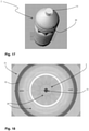
- control unit is programmed to scan the image of the container 2 detected from above eliminating the central zone of the image corresponding to the top/mouth/cap 31 of the container 2 so that it analyses the circular crown which is around the central zone and which corresponds to the lateral surface of the container 2 (see Figure 18 wherein the zone of the image corresponding to the cap 31 is obscured).
- the detector 19 is synchronised with the infeed means 3 and with the infeed transfer starwheel so as to perform the detecting of the container 2 when the latter reaches a detection zone.
- the detecting zone extends from the infeed station 4 to the loading station 6.
- the detection of the initial orientation of the container 2 consists in a recognition of a "spot 20" of the container 2 on the basis of which the control unit calculates (by electronic processing of the image) the initial orientation of the container 2.
- the control unit is configured to calculate the angle of rotation of the support 14 as a function of the rotation performed by the starwheel for carrying the container 2 from a detection zone (wherein the detector 19 detects the initial orientation of the container 2) to the loading station 6.
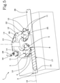
- Figures 3 and 4 show that the container 2 has undergone a rotation of approximately 180° around the axis of rotation of the transfer starwheel.
- the control unit will take into consideration that from the infeed station 4 (where the detection preferably occurs) to the loading station 6, the container 2 has undergone a rotation of approximately 180°.
- control unit is configured to detect orientation of the container 2 by analysing the image detected in which it is possible to identify a recognition mark of the container 2 or a predetermined "spot 20".
- Figures 1 to 8 show, for example, the recognition mark, defined aa a tab of the can, whilst Figures 9 to 16 show the recognition mark as a "spot 20" made on the neck of the bottle.
- the identification mark could be a "spot” made on the lateral surface of the container 2.
- the detector 19 is configured for detecting from above also the lateral surface of the container (according to a perspective view from above) which is then analysed.
- the detector 19 is an image detector 19, preferably a still camera or a video camera.
- the detector 19 is positioned outside the outer horizontal edge of the carousel 12 in such a way as to eliminate protrusions, along the perimeter of the carousel 12, linked to the supporting structure 14 of the one or more detectors (as described in prior art).
- the detector 19 is positioned above the containers 2 and is configured to detect the orientation of the container 2 from the top down.
- the detector 19 is positioned above the infeed means 3 and the transfer unit 5 and is spaced from the latter by a predetermined distance which is greater than the height of the containers 2 to be processed.
- the detector 19 again faces the top of the container 2 and is configured to perform a detection from above.
- the detector 19 may detect an image of a top surface of the container 2 (for example, cap 31 or tab of the can); this operation not being possible in the carousel 12 due to the presence of the units 16 for holding the containers 2 which cover the top surface.
- this invention makes it possible to detect a "spot 20" of a container 2 positioned at its top or lateral surface (for example the tab of the can).
- the detector 19 is preferably configured to receive rays for detecting (light rays reflected by the container 2) the framed image of the container 2. In this way, the detector 19 detects the image of the framed part of the container 2.
- the detector 19 since the detector 19 is configured to perform a detection from above, the rays for detecting propagate along a path substantially parallel to the main axis of extension of the container 2.
- the detector 19 preferably comprises a deflection system 21 for deflecting the rays of the framed image configured to detect an image also of the side walls of the framed container 2.
- the system 21 for deflection from above is configured for deflecting the rays coming from the lateral surfaces of the container 2.
- the deflection system 21 is preferably interposed between a snap-on shutter of the image of the detector 19 and an underlying container 2.
- the deflection system 21 comprises a telecentric lens and/or one or more Fresnel lenses and/or one or more hypercentric lenses and/or a system of hypercentric lenses and/or a cylinder 32 having a reflecting inside lateral surface.
- the deflection system 21 comprises a telecentric lens and/or one or more Fresnel lenses and/or one or more hypercentric lenses and/or a system of hypercentric lenses and/or a cylinder 32 having a reflecting inside lateral surface.
- Figure 18 shows an example of the image of the lateral surface of a container 2 reflected from the mirror as it is detected from above by the detector 19. More specifically, in the image the "spot" 20 is represented by the text in relief (spot 20) beneath which the label will be applied.
- the central image represents the direct image of the container 2 (not reflected) in which it is possible to see the text in relief (spot 20) beneath which the label will be applied.
- control unit is configured to rotate the support 14 of the carousel 12 on which the detected container 2 is loaded by the angle calculated during the movement of the carousel 12 in such a way that in the first stretch of movement of the carousel 12 starting from loading station 6, the container 2 is oriented directly in the final orientation without carrying out any complete revolutions on itself for the detection of the entire lateral surface.
- the machine 1 comprises a further detector 30 positioned along the perimeter of the carousel and downstream of the loading station 6. More specifically, the further detector 30 is configured to detect an image of the container 2 once the latter has rotated about itself by the angle calculated by the support 14. In other words, the further detector 30 is configured for detecting the final orientation of the container 2 in such a way as to check for any deviations to the final orientation of the container 2 relative to a final pre-calculated theoretical orientation (for example in order obtain a correct labelling).
- control unit is connected to the further detector 30 and is configured for:
- the further detector 30 is physically located in a position spaced from the loading station 6 along the periphery of the carousel 12.
- the further detector 30 is a detector of images (stills camera) and/or videos (video camera) of known type.
- the machine 1 also comprises an outfeed transfer unit 22 synchronized in movement with the carousel 12 and configured to remove the containers 2 one at a time from the supports 14 of the carousel 12 at an unloading station 23 spaced from the loading station 6 along the feed path.
- the outfeed transfer unit 22 is configured to carry each container 2 picked up to an outfeed station 24.
- the infeed transfer unit 22 comprises an infeed transfer starwheel rotatable about a respective axis of rotation 29.
- the outfeed transfer starwheel comprises a plurality of housings 10, in which each container 2 is inserted during the transfer from the unloading station 23 to the outfeed station 24.
- each housing 10 comprises retaining means 7 in a position similar to those defined for the infeed transfer starwheel.
- the means 7 for holding in position are not present, but there is a semi-circular contact panel 25 located along a peripheral stretch of the transfer starwheel from the unloading station 23 to the outfeed station 24 to prevent the containers 2 from escaping from the respective housings 10.
- the machine 1 comprises outfeed means 26 extending away from the outfeed station 24 and configured to carry each container 2 away from the carousel 12.
- the outfeed means 26 comprise a conveyor belt and, even more preferably, the conveyor belt is a part of the conveyor belt of the infeed means 3.
- This invention also relates to a method for moving the containers 2 to be processed along the feed path.
- the method is derived directly from what described above relative to the machine 1 for moving containers 2 which is incorporated here in its entirety.
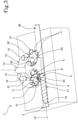
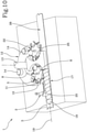
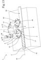
- the method comprises a step of feeding the containers 2 to an infeed station 4 along the feed path ( Figures 2 and 10 ). Subsequently, the method comprises transferring one container 2 at a time from the infeed station 4 to the loading station 6 using the transfer unit 5 ( Figures 3 , 4 , 11 , 12 ).
- the transferring step is accomplished by keeping the orientation of each container 2 fixed relative to the transfer unit itself during travel from the infeed station 4 to the loading station 6. Moreover, the transfer step comprises loading the container 2 onto a support 14 of the carousel 12 when the support 14 is positioned at the loading station 6.
- the method comprises detecting the initial orientation of each container 2, relative to the central axis of extension thereof, at a position of the container 2 upstream of the loading station 6 in the carousel 12 along the feed path. Moreover, the method comprises calculating the angle of rotation of the support 14 in order to turn the container 2 loaded thereon to a predetermined final orientation as a function of the initial orientation detected and of the movement imparted by the transfer unit. Lastly, the method comprises a step of rotating the support 14 by the calculated angle of rotation after the container 2 has been placed on the support 14 so as to turn the container 2 to the predetermined final orientation.
- the detecting step occurs at the infeed station 4.
- the detecting step occurs outside the horizontal edge of the carousel 12.
- the detecting step occurs from above relative to each container 2 in such a way that the detector 19 is positioned above the container 2 and facing a top of the latter.
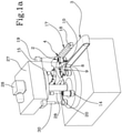
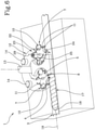
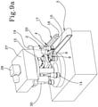
- Figures 1a , 5 , 9a and 13 shows the step wherein the support 14 of the carousel 12 rotates by the calculated angle in such a way as to reach the predetermined final orientation.
- the step of detecting the initial orientation of the container comprises a sub-step of processing the image captured by the detector 19 scanning the peripheral area around the top or mouth or cap 31 of the container 2 present in the image and corresponding to the lateral surface of the container 2. In that way, it is possible to determine the initial orientation of the container 2 as a function of a "spot" 20 located on the lateral surface.
- the invention achieves the preset aims.
- the machine 1 for moving the containers 2 reduces the dimensions for the support 14 of the sensor along the edge of the carousel 12 since no support 14 is present for the sensor along the carousel 12 as the sensor is located upstream of the loading station 6.
- this invention allows the timing and the spaces for detecting the orientation of the container 2 to be optimized.
- the relative orientation is recognised and also the angle of rotation necessary to carry it to the final predetermined orientation.
- the container 2 is rotated only by the angle necessary to carry it to a final position and does not need a complete initial rotation for the scanning of the lateral surface (as in the prior art). Consequently, the complete operation for positioning the container 2 in the final orientation occupies an angle of carousel 12 less than that of the prior art.
- the detector 19 is applied upstream of the loading station 6 and outside of the carousel 12, it is possible to detect the container 2 from the top downwards in such a way as to detect a "spot 20" of the container 2 present at a relative top or lateral surface.
Landscapes
- Engineering & Computer Science (AREA)
- Mechanical Engineering (AREA)
- Labeling Devices (AREA)
- Specific Conveyance Elements (AREA)
- Control Of Conveyors (AREA)
Claims (12)
- Maschine (1) zum Bewegen von zu prozessierenden Behältern (2) entlang einer Zuführstrecke, umfassend:- Einlaufmittel (3) zum Zuführen von Behältern (2) zu einer Einlaufstation (4);- eine Einlaufübergabeeinheit (5), die sich an der Einlaufstation (4) befindet und so konfiguriert ist, dass sie die einzelnen Behälter (2) aufnimmt und sie zu einer Ladestation (6) entlang der Zuführstrecke transportiert;- ein Karussell (12), das um seine Drehwelle drehbar ist und eine Vielzahl von drehbaren Trägern (14) umfasst, die um seinen Umfang angeordnet sind, um die jeweiligen Behälter (2) zu tragen; wobei das Karussell (12) an der Ladestation (6) montiert ist und dessen Bewegung mit der Einlaufübergabeeinheit (5) derart synchronisiert ist, dass jeder von der Übergabeeinheit (5) entladene Behälter (2) auf einen entsprechenden Träger (14) des Karussells (12) gestellt wird;- Mittel zum Bewegen jedes Trägers (14) und so konfiguriert, dass dieser während der Bewegung des Karussells (12) um seine eigene Achse um einen Drehwinkel dreht;- einen Detektor (19), der konfiguriert ist, um ein Bild jedes Behälters (2) zu erfassen, und der stromaufwärts der Ladestation (6) in dem Karussell (12) entlang der Zuführstrecke positioniert ist; wobei der Detektor (19) über den Behältern (2) positioniert ist und konfiguriert ist, um ein Bild jedes Behälters (2) von oben nach unten zu erfassen;- eine Steuereinheit, die mit dem Detektor (19) und den Mitteln zum Bewegen jedes Trägers (14) des Karussells (12) in Wirkverbindung steht und dafür konfiguriert ist, um:- das vom Detektor (19) erfasste Bild des Behälters (2) zu empfangen;- die Ausrichtung jedes Behälters (2) relativ zu seiner Mittelausdehnungsachse zu bestimmen;- den Drehwinkel des Trägers (14) zu berechnen, um den darauf geladenen Behälter (2) in Abhängigkeit von der erfassten Anfangsorientierung in eine vorgegebene Endausrichtung zu drehen;- die Mittel zum Bewegen anzutreiben, um den Träger (14) um den berechneten Drehwinkel zu drehen, nachdem der Behälter (2) auf den Träger (14) gestellt wurde, um den Behälter (2) in die vorgegebene Endausrichtung zu drehen;- den Umfangsbereich um die Oberseite oder den Mund oder die Kappe (31) des Behälters (2), der in dem vom Detektor (19) erfassten Bild vorhanden ist, entsprechend der Seitenfläche des Behälters (2) abzutasten, um die Anfangsausrichtung des Behälters (2) in Abhängigkeit von einer auf der Seitenfläche positionierten Erkennungsmarke (20) zu bestimmen; dadurch gekennzeichnet, dass die Übergabeeinheit (5) Haltemittel (7) zum Behalten der Position der Behälter (2) relativ zu der Übergabeeinheit selbst umfasst, so dass die Ausrichtung jedes Behälters (2) in Bezug auf seine eigene Hauptausdehnungsachse (28) beibehalten wird, wenn er von der Einlaufstation (4) zur Ladestation (6) transportiert wird;
und dass die Steuereinheit konfiguriert ist, um den Drehwinkel des Trägers (14) auch in Abhängigkeit von der von der Übergabeeinheit (5) zum Transportieren des Behälters (2) aus einem Erfassungsbereich vermittelten Bewegung zu berechnen, wobei der Detektor (19) die Anfangsausrichtung des Behälters (2) zur Ladestation (6) erfasst. - Maschine (1) nach Anspruch 1, dadurch gekennzeichnet, dass der Detektor (19) zwischen der Einlaufstation (4) und der Ladestation (6) entlang einer Wegstrecke zur Zuführung des an der Übergabeeinheit (5) positionierten Behälters (2) positioniert ist; wobei die Übergabeeinheit (5) eine Vielzahl von Gehäusen (10) zur Aufnahme der jeweiligen Behälter umfasst, wobei jedes Gehäuse (10) an einem unteren Teil des Behälters (2) derart positioniert ist, dass der größte Teil der Seitenwand des Behälters (2) für die Erfassung frei bleibt.
- Maschine (1) nach Anspruch 1, dadurch gekennzeichnet, dass sich der Detektor (19) an der Einlaufstation (4) befindet.
- Maschine (1) nach einem der vorhergehenden Ansprüche, dadurch gekennzeichnet, dass der Detektor (19) so konfiguriert ist, dass er Strahlen zum Erfassen des gerahmten Bildes des Behälters (2) empfängt; wobei der Detektor (19) ein Ablenksystem (21) zum Ablenken der Strahlen des gerahmten Bildes umfasst und so konfiguriert ist, dass er ein Bild der Seitenwände des gerahmten Behälters (2) erfasst.
- Maschine (1) nach Anspruch 4, dadurch gekennzeichnet, dass das Ablenksystem (21) eine telezentrische Linse und/oder eine oder mehrere Fresnellinsen und/oder eine oder mehrere hyperzentrische Linsen und/oder ein System von hyperzentrischen Linsen und/oder einen Zylinder (32) mit einer reflektierenden Innenseitenfläche umfasst.
- Maschine (1) nach einem der vorhergehenden Ansprüche, dadurch gekennzeichnet, dass der Detektor (19) ein Bilddetektor (19), vorzugsweise eine Standbildkamera oder eine Videokamera ist.
- Maschine (1) nach einem der vorhergehenden Ansprüche, dadurch gekennzeichnet, dass die Übergabeeinheit (5) ein um ihre Drehachse drehendes Sternrad und mit mehreren um ihren Umfang angeordneten Gehäusen (10) zur Aufnahme der zu überführenden Behälter (2) umfasst; wobei die Haltemittel (7) an jedem Gehäuse (10) so positioniert sind, dass sie den Behälter (2) in einer Position innerhalb des Gehäuses (10) behalten; wobei das Drehsternrad mit der Bewegung des Karussells (12) so synchronisiert ist, dass es einen einzelnen Behälter (2) zu den jeweiligen Trägern (14) des Karussells (12) transportiert.
- Maschine (1) nach einem der vorhergehenden Ansprüche, dadurch gekennzeichnet, dass sie Abstandsmittel (17) zum Abstandhalten der Behälter (2) umfasst, die mit den Einlaufmitteln (3) in Wirkverbindung stehen und sich entlang mindestens eines Teils der Einlaufmittel (3) bis zur Einlaufstation (4) erstrecken, um einen Behälter (2) von einem anderen zu beabstanden, bevor er die Einlaufstation (4) erreicht.
- Maschine (1) nach einem der vorhergehenden Ansprüche, dadurch gekennzeichnet, dass sie eine Abführübergabeeinheit (22) umfasst, die mit der Bewegung des Karussells (12) synchronisiert ist und so konfiguriert ist, dass sie die einzelnen Behälter (2) von den Trägern (14) des Karussells (12) an einer Entladestation (23) entfernt, die von der Ladestation entlang der Zuführstrecke beabstandet ist; wobei die Abführübergabeeinheit (22) so konfiguriert ist, dass sie jeden entnommenen Behälter (2) bis eine Abführstation (24) transportiert; wobei die Maschine (1) Abführübergabemittel (26) umfasst, die sich von der Abführstation (24) weg erstrecken und so konfiguriert sind, dass sie jeden Behälter (2) von dem Karussell (12) wegtransportieren.
- Maschine (1) nach einem der vorhergehenden Ansprüche, dadurch gekennzeichnet, dass das Karussell (12) eine Vielzahl von Halteeinheiten (16) zum Halten der Behälter (2) umfasst und die über und an den Trägern (14) des Karussells (12) positioniert sind; wobei jede Halteeinheit (16) aus einer angehobenen Position in eine abgesenkte Position relativ zu dem Behälter (2) derart bewegbar ist, dass sie ihn gegen den Träger (14) nach dem Laden des Behälters (2) auf diesen gedrückt hält.
- Maschine (1) nach einem der vorhergehenden Ansprüche, dadurch gekennzeichnet, dass sie einen weiteren Detektor (30) umfasst, der sich entlang des Umfangs des Karussells (12) und stromabwärts der Ladestation (6) befindet, um die Endausrichtung des Behälters (2) nach seiner Drehung um sich selbst durch den berechneten Winkel zu erfassen; wobei die Steuereinheit mit dem weiteren Detektor (30) verbunden und konfiguriert ist:- um die Information über die Endausrichtung des Behälters (2) vom weiteren Detektor (30) zu erhalten;- um die Informationen zu verarbeiten und die Winkelabweichung des Behälters (2) zwischen der erfassten Endausrichtung und einer vorgegebenen theoretischen Endausrichtung zu berechnen;- die Bewegungsmittel so anzutreiben, dass der Träger (14) um einen Winkel entsprechend der berechneten Winkelabweichung so gedreht wird, dass der Behälter (2) in die theoretische Endausrichtung gedreht wird.
- Verfahren zum Bewegen von zu prozessierenden Behältern (2) entlang einer Zuführstrecke, umfassend die folgenden Schritte:- Zuführen der Behälter (2) zu einer Einlaufstation (4) entlang der Zuführstrecke;- Überführen eines einzelnen Behälters (2) von der Einlaufstation (4) zu einer Ladestation (6) unter Verwendung von einer Übergabeeinheit (5);- wobei der Übergabeschritt das Beladen des Behälters (2) auf einen Träger (14) eines Karussells (12) umfasst, das um seine Drehwelle drehbar ist, wenn der Träger (14) an der Ladestation (6) positioniert wird; Erfassen eines Bildes von jedem Behälter (2) relativ zu dessen Mittelausdehnungsachse an einer Position, an der der Behälter (2) stromaufwärts der Ladestation (6) im Karussell (12) entlang der Zuführstrecke ist; wobei der Erfassungsschritt von oben relativ zu jedem Behälter (2) durch einen Detektor (19) ausgeführt wird, der über dem Behälter (2) positioniert und dessen Oberseite zugewandt ist;- die Ausrichtung jedes Behälters (2) relativ zu dessen Mittelausdehnungsachse zu bestimmen;- Berechnen des Drehwinkels des Trägers (14), um den darauf geladenen Behälter (2) in Abhängigkeit von der erfassten Anfangsorientierung in eine vorgegebene Endausrichtung zu drehen;- Drehen des Trägers (14) um den berechneten Drehwinkel, nachdem der Behälter (2) auf den Träger (14) gestellt wurde, um den Behälter (2) in die vorbestimmte Endausrichtung zu drehen;
der Schritt des Bestimmens der Anfangsausrichtung des Behälters (2) einen Teilschritt des Prozessierens des durch den Detektor (19) ermittelten Bildes umfasst, der den Umfangsbereich um die Oberseite oder den Mund oder die Kappe (31) des Behälters (2), der in dem Bild vorhanden ist und der Seitenfläche des Behälters (2) entspricht, abtastet, um die Anfangsausrichtung des Behälters (2) in Abhängigkeit von einer auf der Seitenfläche positionierten Erkennungsmarke (20) zu bestimmen;
dadurch gekennzeichnet, dass der Übergabeschritt durchgeführt wird, indem die Ausrichtung jedes Behälters (2) relativ zu der Übergabeeinheit selbst während der Fahrt von der Einlaufstation (4) zur Ladestation (6) fixiert gehalten wird; und dass der Schritt des Berechnens des Drehwinkels des Trägers (14) unter Berücksichtigung der von der Übergabeeinheit (5) zum Transportieren des Behälters (2) aus einem Erfassungsbereich vermittelten Bewegung ausgeführt wird, wobei der Detektor (19) die Anfangsausrichtung des Behälters (2) zur Ladestation (6) erfasst.
Applications Claiming Priority (2)
| Application Number | Priority Date | Filing Date | Title |
|---|---|---|---|
| ITVR20140292 | 2014-11-27 | ||
| PCT/IB2015/058364 WO2016083920A2 (en) | 2014-11-27 | 2015-10-29 | Machine for moving containers to be processed |
Publications (3)
| Publication Number | Publication Date |
|---|---|
| EP3209571A2 EP3209571A2 (de) | 2017-08-30 |
| EP3209571B1 EP3209571B1 (de) | 2018-08-01 |
| EP3209571B2 true EP3209571B2 (de) | 2022-02-23 |
Family
ID=52293099
Family Applications (1)
| Application Number | Title | Priority Date | Filing Date |
|---|---|---|---|
| EP15805276.1A Active EP3209571B2 (de) | 2014-11-27 | 2015-10-29 | Maschine und verfahren zur ausrichtung von behältern |
Country Status (6)
| Country | Link |
|---|---|
| US (1) | US10183772B2 (de) |
| EP (1) | EP3209571B2 (de) |
| AU (1) | AU2015352059B2 (de) |
| CA (1) | CA2968028A1 (de) |
| ES (1) | ES2694038T5 (de) |
| WO (1) | WO2016083920A2 (de) |
Families Citing this family (22)
| Publication number | Priority date | Publication date | Assignee | Title |
|---|---|---|---|---|
| NL2017196B1 (en) * | 2016-07-20 | 2018-01-26 | Sluis Cigar Machinery Bv | Simulated cigarette parts reorienting apparatus |
| EP4194378B1 (de) | 2016-09-09 | 2024-11-20 | The Procter & Gamble Company | System und verfahren zur unabhängigen führung von fahrzeugen und zur abgabe von behältern und verschlüssen an einheitsbetriebsstationen |
| CN109690430B (zh) | 2016-09-09 | 2022-06-24 | 宝洁公司 | 基于需求生产产品的系统和方法 |
| CN106395033B (zh) * | 2016-09-14 | 2019-06-11 | 青岛亚坦文具有限公司 | 一种自动化修正液灌装装置 |
| IT201700055395A1 (it) * | 2017-05-22 | 2018-11-22 | Telerobot S P A | Dispositivo di montaggio per oggetti plastici |
| IT201800001387A1 (it) * | 2018-01-19 | 2019-07-19 | Gd Spa | Macchina e metodo per il riempimento di cartucce per generatori di aerosol |
| US20190300288A1 (en) * | 2018-03-29 | 2019-10-03 | Philip K. Morin | Alignment and dispensing apparatus for linear parts |
| IT201800005482A1 (it) * | 2018-05-17 | 2019-11-17 | Apparato per l'ispezione di contenitori | |
| CN110759040A (zh) * | 2019-10-25 | 2020-02-07 | 东莞理工学院 | 一种应用高维数据检测的输送装盖设备 |
| US20210188473A1 (en) * | 2019-12-19 | 2021-06-24 | Eliqs Llc | Pre-Filled and Pre-Sealed Beverage Container Sleeve Applicator |
| FR3105753B1 (fr) | 2019-12-26 | 2022-01-07 | Sidel Participations | "Procédé d'orientation angulaire de corps creux dans une installation de fabrication de récipients" |
| EP4085010A4 (de) | 2019-12-30 | 2024-12-25 | Accraply, LLC, A Barry-Wehmiller Packaging Company | Maschine zum anbringen von etiketten oder anderen materialien an behältern |
| CN111307826B (zh) * | 2020-03-03 | 2023-03-31 | 桂林电子科技大学 | 一种瓶内粉末中异物在线视觉检测设备及方法 |
| EP3943428A1 (de) * | 2020-07-24 | 2022-01-26 | WestRock Packaging Systems, LLC | Orientierungsmodul |
| CN114684601B (zh) * | 2020-12-31 | 2025-09-30 | 安徽文王酿酒股份有限公司 | 一种用于料瓶转动的转动机构及装置 |
| IT202100003524A1 (it) * | 2021-02-16 | 2022-08-16 | Ecocaps S R L | Sistema di orientamento lattina all’interno di una macchina per la lavorazione di lattine e relativa macchina |
| IT202100017858A1 (it) * | 2021-07-07 | 2023-01-07 | Smi Spa | Macchina per la stampa di informazioni su un contenitore |
| DE102022122377A1 (de) * | 2022-09-05 | 2024-03-07 | Krones Aktiengesellschaft | Behältertransportsystem und Verfahren zum Transport von Behältern |
| CN117105149B (zh) * | 2023-08-02 | 2025-07-25 | 上海和熠实业有限公司 | 一种西林瓶自动装药装置 |
| CN117023091B (zh) * | 2023-10-09 | 2023-12-12 | 南京比逊弥特智能科技有限公司 | 具有全自动剔除反瓶功能的自动循环高速理瓶系统及方法 |
| WO2025117647A1 (en) * | 2023-11-27 | 2025-06-05 | Westrock Packaging Systems, Llc | Orientation module with turning members for turning articles having different dimensions |
| CN120171893A (zh) * | 2025-04-02 | 2025-06-20 | 江苏新美星包装机械股份有限公司 | 一种装盖贴标一体机 |
Family Cites Families (21)
| Publication number | Priority date | Publication date | Assignee | Title |
|---|---|---|---|---|
| DE1949135U (de) | 1966-08-27 | 1966-11-03 | Anker Maschb G M B H | Vorrichtung zur ausrichtung von flaschen oder aehnlichen gefaessen vor der etikettierung durch drehen um ihre achse. |
| DE1805010B1 (de) | 1968-10-24 | 1970-04-30 | Otto Sick Metallwarenfabrik Fa | Einrichtung zum Ausrichten von Flaschen in Verkapselungsmaschinen |
| DE7512621U (de) | 1975-04-19 | 1976-10-21 | Jagenberg-Werke Ag, 4000 Duesseldorf | Vorrichtung zum ausrichten rotationssymmetrischer koerper, insbesondere flaschen, in einer flaschenbehandlungsmaschine, insbesondere etikettiermaschine |
| US4124112A (en) * | 1977-05-23 | 1978-11-07 | Owens-Illinois, Inc. | Odd-shaped container indexing starwheel |
| DE2740220C2 (de) | 1977-09-07 | 1982-10-28 | Kronseder, Hermann, 8404 Wörth | Vorrichtung zum Ausrichten von Flaschen vor dem Etikettieren |
| JPS571041A (en) * | 1980-06-02 | 1982-01-06 | Shibuya Kogyo Co Ltd | Labeller |
| DE3022343C2 (de) * | 1980-06-14 | 1983-10-20 | Kronseder, Hermann, 8404 Wörth | Vorrichtung zum Ausrichten von Flaschen o.dgl., insbesondere in Etikettiermaschinen |
| US5058724A (en) | 1990-11-08 | 1991-10-22 | Hinton Gaylen R | Apparatus and method for orienting articles and containers |
| US5243400A (en) | 1992-04-27 | 1993-09-07 | Owens-Brockway Glass Container Inc. | Inspection of transparent containers |
| US5233186A (en) | 1992-06-19 | 1993-08-03 | Owens-Brockway Glass Container Inc. | Inspection of transparent containers with opposing reflection means |
| US5369713A (en) | 1992-07-09 | 1994-11-29 | Schwartz; Nira | Inspection method using area of interest (AOI) analysis |
| US5478422A (en) * | 1993-09-16 | 1995-12-26 | B & H Manufacturing Company, Inc. | Computer controlled turret type labeling machine |
| IT1307230B1 (it) * | 1999-03-31 | 2001-10-30 | Robino & Galandrino Spa | Procedimento ed apparecchiatura per la centratura e l'orientamentodelle capsule di sigillo di bottiglie di vino spumante e simili. |
| AU2002259332A1 (en) * | 2001-06-01 | 2002-12-16 | Interactive Packaging Group, Ltd. | Method, machine and object for placement of multiple labels |
| DE10145455A1 (de) * | 2001-09-14 | 2003-04-24 | Krones Ag | Maschine zum Ausstatten von Arikeln |
| DE20115480U1 (de) | 2001-09-19 | 2002-05-16 | Heuft Systemtechnik Gmbh, 56659 Burgbrohl | Vorrichtung zum Anbringen von Etiketten an Behältern |
| DE102006026618A1 (de) | 2006-09-02 | 2008-03-13 | Khs Ag | Verfahren zum lagegenauen Aufbringen von Etiketten sowie Etikettiermaschine |
| DE102009005180A1 (de) | 2009-01-15 | 2010-07-22 | Khs Ag | Behälterbehandlungsmaschine |
| DE102009014663B4 (de) * | 2009-03-27 | 2013-03-14 | Khs Gmbh | Vorrichtung und Verfahren zur Erfassung der Drehposition zumindest einer zur Aufnahme eines Behälters vorgesehenen Drehvorrichtung |
| IT1396099B1 (it) | 2009-10-20 | 2012-11-09 | Makro Labelling Srl | Convogliatore per contenitori, quali bottiglie, da trattare e per contenitori trattati per macchine operatrici del tipo a giostra rotante. |
| IT1403497B1 (it) | 2010-12-27 | 2013-10-17 | Makro Labelling Srl | "dispositivo di rilevamento per contenitori in movimento" |
-
2015
- 2015-10-29 WO PCT/IB2015/058364 patent/WO2016083920A2/en not_active Ceased
- 2015-10-29 EP EP15805276.1A patent/EP3209571B2/de active Active
- 2015-10-29 AU AU2015352059A patent/AU2015352059B2/en active Active
- 2015-10-29 ES ES15805276T patent/ES2694038T5/es active Active
- 2015-10-29 US US15/529,909 patent/US10183772B2/en active Active
- 2015-10-29 CA CA2968028A patent/CA2968028A1/en not_active Abandoned
Also Published As
| Publication number | Publication date |
|---|---|
| EP3209571A2 (de) | 2017-08-30 |
| CA2968028A1 (en) | 2016-06-02 |
| ES2694038T3 (es) | 2018-12-17 |
| WO2016083920A3 (en) | 2016-08-18 |
| WO2016083920A2 (en) | 2016-06-02 |
| AU2015352059A1 (en) | 2017-06-15 |
| EP3209571B1 (de) | 2018-08-01 |
| US10183772B2 (en) | 2019-01-22 |
| ES2694038T5 (es) | 2022-05-18 |
| US20180170596A1 (en) | 2018-06-21 |
| AU2015352059B2 (en) | 2019-11-21 |
Similar Documents
| Publication | Publication Date | Title |
|---|---|---|
| EP3209571B1 (de) | Maschine und verfahren zur ausrichtung von behältern | |
| US9623990B2 (en) | Machine for applying threaded caps to containers | |
| US8477185B2 (en) | System for the angular orientation and detection of containers in labelling machines | |
| RU2453493C1 (ru) | Установка для укупоривания емкостей и способ ориентации на емкости | |
| US20160137326A1 (en) | Apparatus and method for handling articles | |
| CN101511681A (zh) | 用于位置正确地施加标签的方法以及贴标机 | |
| US10519018B2 (en) | Receptacle handling apparatus for filing and capping receptacles | |
| US7478660B2 (en) | Labelling and/or marking machine | |
| WO2008072070A2 (en) | System for detecting the angular positioning of containers | |
| CN107107628A (zh) | 贴标机 | |
| US20070127018A1 (en) | Inspection machine | |
| EP3286553B1 (de) | Vorrichtung und verfahren zur optischen inspektion von vorformlingen | |
| US20170183116A1 (en) | Carousel for processing containers | |
| US20240076089A1 (en) | Container transport system and method for transporting containers | |
| JP7168845B2 (ja) | キャップ検査装置及びキャップ検査方法 | |
| CN114174177A (zh) | 用于定向容器的设备和方法 | |
| EP3593272B1 (de) | Vorrichtung und verfahren zum lesen von einer auf behältern, die sich entlang eines förderers bewegen, aufgedruckten markierung | |
| JP5293003B2 (ja) | キャッパ | |
| EP4499534A1 (de) | System und verfahren zur inspektion zylindrischer behälter | |
| CN115991451A (zh) | 通过容器封闭件封闭容器 | |
| JP7208462B2 (ja) | 容器方向判定装置および容器搬送装置 | |
| JP2023179171A (ja) | 容器搬送装置 | |
| WO2022214932A1 (en) | Apparatus and method for capping containers | |
| JP2006007227A (ja) | 蓋装着装置及び容器のマーキング方法 | |
| IT201800002921A1 (it) | Dispositivo e metodo di ispezione |
Legal Events
| Date | Code | Title | Description |
|---|---|---|---|
| STAA | Information on the status of an ep patent application or granted ep patent |
Free format text: STATUS: THE INTERNATIONAL PUBLICATION HAS BEEN MADE |
|
| PUAI | Public reference made under article 153(3) epc to a published international application that has entered the european phase |
Free format text: ORIGINAL CODE: 0009012 |
|
| STAA | Information on the status of an ep patent application or granted ep patent |
Free format text: STATUS: REQUEST FOR EXAMINATION WAS MADE |
|
| STAA | Information on the status of an ep patent application or granted ep patent |
Free format text: STATUS: EXAMINATION IS IN PROGRESS |
|
| 17P | Request for examination filed |
Effective date: 20170525 |
|
| AK | Designated contracting states |
Kind code of ref document: A2 Designated state(s): AL AT BE BG CH CY CZ DE DK EE ES FI FR GB GR HR HU IE IS IT LI LT LU LV MC MK MT NL NO PL PT RO RS SE SI SK SM TR |
|
| AX | Request for extension of the european patent |
Extension state: BA ME |
|
| 17Q | First examination report despatched |
Effective date: 20170808 |
|
| DAV | Request for validation of the european patent (deleted) | ||
| DAX | Request for extension of the european patent (deleted) | ||
| GRAP | Despatch of communication of intention to grant a patent |
Free format text: ORIGINAL CODE: EPIDOSNIGR1 |
|
| STAA | Information on the status of an ep patent application or granted ep patent |
Free format text: STATUS: GRANT OF PATENT IS INTENDED |
|
| INTG | Intention to grant announced |
Effective date: 20180410 |
|
| GRAS | Grant fee paid |
Free format text: ORIGINAL CODE: EPIDOSNIGR3 |
|
| GRAA | (expected) grant |
Free format text: ORIGINAL CODE: 0009210 |
|
| STAA | Information on the status of an ep patent application or granted ep patent |
Free format text: STATUS: THE PATENT HAS BEEN GRANTED |
|
| AK | Designated contracting states |
Kind code of ref document: B1 Designated state(s): AL AT BE BG CH CY CZ DE DK EE ES FI FR GB GR HR HU IE IS IT LI LT LU LV MC MK MT NL NO PL PT RO RS SE SI SK SM TR |
|
| REG | Reference to a national code |
Ref country code: GB Ref legal event code: FG4D |
|
| REG | Reference to a national code |
Ref country code: CH Ref legal event code: EP Ref country code: AT Ref legal event code: REF Ref document number: 1024000 Country of ref document: AT Kind code of ref document: T Effective date: 20180815 |
|
| REG | Reference to a national code |
Ref country code: IE Ref legal event code: FG4D |
|
| REG | Reference to a national code |
Ref country code: DE Ref legal event code: R096 Ref document number: 602015014442 Country of ref document: DE |
|
| REG | Reference to a national code |
Ref country code: FR Ref legal event code: PLFP Year of fee payment: 4 |
|
| REG | Reference to a national code |
Ref country code: NL Ref legal event code: MP Effective date: 20180801 |
|
| REG | Reference to a national code |
Ref country code: ES Ref legal event code: FG2A Ref document number: 2694038 Country of ref document: ES Kind code of ref document: T3 Effective date: 20181217 |
|
| REG | Reference to a national code |
Ref country code: LT Ref legal event code: MG4D |
|
| REG | Reference to a national code |
Ref country code: AT Ref legal event code: MK05 Ref document number: 1024000 Country of ref document: AT Kind code of ref document: T Effective date: 20180801 |
|
| PG25 | Lapsed in a contracting state [announced via postgrant information from national office to epo] |
Ref country code: NO Free format text: LAPSE BECAUSE OF FAILURE TO SUBMIT A TRANSLATION OF THE DESCRIPTION OR TO PAY THE FEE WITHIN THE PRESCRIBED TIME-LIMIT Effective date: 20181101 Ref country code: BG Free format text: LAPSE BECAUSE OF FAILURE TO SUBMIT A TRANSLATION OF THE DESCRIPTION OR TO PAY THE FEE WITHIN THE PRESCRIBED TIME-LIMIT Effective date: 20181101 Ref country code: PL Free format text: LAPSE BECAUSE OF FAILURE TO SUBMIT A TRANSLATION OF THE DESCRIPTION OR TO PAY THE FEE WITHIN THE PRESCRIBED TIME-LIMIT Effective date: 20180801 Ref country code: NL Free format text: LAPSE BECAUSE OF FAILURE TO SUBMIT A TRANSLATION OF THE DESCRIPTION OR TO PAY THE FEE WITHIN THE PRESCRIBED TIME-LIMIT Effective date: 20180801 Ref country code: AT Free format text: LAPSE BECAUSE OF FAILURE TO SUBMIT A TRANSLATION OF THE DESCRIPTION OR TO PAY THE FEE WITHIN THE PRESCRIBED TIME-LIMIT Effective date: 20180801 Ref country code: IS Free format text: LAPSE BECAUSE OF FAILURE TO SUBMIT A TRANSLATION OF THE DESCRIPTION OR TO PAY THE FEE WITHIN THE PRESCRIBED TIME-LIMIT Effective date: 20181201 Ref country code: GR Free format text: LAPSE BECAUSE OF FAILURE TO SUBMIT A TRANSLATION OF THE DESCRIPTION OR TO PAY THE FEE WITHIN THE PRESCRIBED TIME-LIMIT Effective date: 20181102 Ref country code: LT Free format text: LAPSE BECAUSE OF FAILURE TO SUBMIT A TRANSLATION OF THE DESCRIPTION OR TO PAY THE FEE WITHIN THE PRESCRIBED TIME-LIMIT Effective date: 20180801 Ref country code: RS Free format text: LAPSE BECAUSE OF FAILURE TO SUBMIT A TRANSLATION OF THE DESCRIPTION OR TO PAY THE FEE WITHIN THE PRESCRIBED TIME-LIMIT Effective date: 20180801 Ref country code: FI Free format text: LAPSE BECAUSE OF FAILURE TO SUBMIT A TRANSLATION OF THE DESCRIPTION OR TO PAY THE FEE WITHIN THE PRESCRIBED TIME-LIMIT Effective date: 20180801 Ref country code: SE Free format text: LAPSE BECAUSE OF FAILURE TO SUBMIT A TRANSLATION OF THE DESCRIPTION OR TO PAY THE FEE WITHIN THE PRESCRIBED TIME-LIMIT Effective date: 20180801 |
|
| PG25 | Lapsed in a contracting state [announced via postgrant information from national office to epo] |
Ref country code: AL Free format text: LAPSE BECAUSE OF FAILURE TO SUBMIT A TRANSLATION OF THE DESCRIPTION OR TO PAY THE FEE WITHIN THE PRESCRIBED TIME-LIMIT Effective date: 20180801 Ref country code: HR Free format text: LAPSE BECAUSE OF FAILURE TO SUBMIT A TRANSLATION OF THE DESCRIPTION OR TO PAY THE FEE WITHIN THE PRESCRIBED TIME-LIMIT Effective date: 20180801 Ref country code: LV Free format text: LAPSE BECAUSE OF FAILURE TO SUBMIT A TRANSLATION OF THE DESCRIPTION OR TO PAY THE FEE WITHIN THE PRESCRIBED TIME-LIMIT Effective date: 20180801 |
|
| PG25 | Lapsed in a contracting state [announced via postgrant information from national office to epo] |
Ref country code: RO Free format text: LAPSE BECAUSE OF FAILURE TO SUBMIT A TRANSLATION OF THE DESCRIPTION OR TO PAY THE FEE WITHIN THE PRESCRIBED TIME-LIMIT Effective date: 20180801 Ref country code: EE Free format text: LAPSE BECAUSE OF FAILURE TO SUBMIT A TRANSLATION OF THE DESCRIPTION OR TO PAY THE FEE WITHIN THE PRESCRIBED TIME-LIMIT Effective date: 20180801 Ref country code: CZ Free format text: LAPSE BECAUSE OF FAILURE TO SUBMIT A TRANSLATION OF THE DESCRIPTION OR TO PAY THE FEE WITHIN THE PRESCRIBED TIME-LIMIT Effective date: 20180801 |
|
| REG | Reference to a national code |
Ref country code: DE Ref legal event code: R026 Ref document number: 602015014442 Country of ref document: DE |
|
| PLBI | Opposition filed |
Free format text: ORIGINAL CODE: 0009260 |
|
| PLAX | Notice of opposition and request to file observation + time limit sent |
Free format text: ORIGINAL CODE: EPIDOSNOBS2 |
|
| PG25 | Lapsed in a contracting state [announced via postgrant information from national office to epo] |
Ref country code: SM Free format text: LAPSE BECAUSE OF FAILURE TO SUBMIT A TRANSLATION OF THE DESCRIPTION OR TO PAY THE FEE WITHIN THE PRESCRIBED TIME-LIMIT Effective date: 20180801 Ref country code: DK Free format text: LAPSE BECAUSE OF FAILURE TO SUBMIT A TRANSLATION OF THE DESCRIPTION OR TO PAY THE FEE WITHIN THE PRESCRIBED TIME-LIMIT Effective date: 20180801 Ref country code: SK Free format text: LAPSE BECAUSE OF FAILURE TO SUBMIT A TRANSLATION OF THE DESCRIPTION OR TO PAY THE FEE WITHIN THE PRESCRIBED TIME-LIMIT Effective date: 20180801 |
|
| REG | Reference to a national code |
Ref country code: CH Ref legal event code: PL |
|
| 26 | Opposition filed |
Opponent name: P.E. LABELLERS S.P.A. Effective date: 20190502 |
|
| PLAF | Information modified related to communication of a notice of opposition and request to file observations + time limit |
Free format text: ORIGINAL CODE: EPIDOSCOBS2 |
|
| REG | Reference to a national code |
Ref country code: BE Ref legal event code: MM Effective date: 20181031 |
|
| PG25 | Lapsed in a contracting state [announced via postgrant information from national office to epo] |
Ref country code: LU Free format text: LAPSE BECAUSE OF NON-PAYMENT OF DUE FEES Effective date: 20181029 Ref country code: MC Free format text: LAPSE BECAUSE OF FAILURE TO SUBMIT A TRANSLATION OF THE DESCRIPTION OR TO PAY THE FEE WITHIN THE PRESCRIBED TIME-LIMIT Effective date: 20180801 |
|
| PG25 | Lapsed in a contracting state [announced via postgrant information from national office to epo] |
Ref country code: LI Free format text: LAPSE BECAUSE OF NON-PAYMENT OF DUE FEES Effective date: 20181031 Ref country code: SI Free format text: LAPSE BECAUSE OF FAILURE TO SUBMIT A TRANSLATION OF THE DESCRIPTION OR TO PAY THE FEE WITHIN THE PRESCRIBED TIME-LIMIT Effective date: 20180801 Ref country code: CH Free format text: LAPSE BECAUSE OF NON-PAYMENT OF DUE FEES Effective date: 20181031 Ref country code: BE Free format text: LAPSE BECAUSE OF NON-PAYMENT OF DUE FEES Effective date: 20181031 |
|
| PLBB | Reply of patent proprietor to notice(s) of opposition received |
Free format text: ORIGINAL CODE: EPIDOSNOBS3 |
|
| PG25 | Lapsed in a contracting state [announced via postgrant information from national office to epo] |
Ref country code: MT Free format text: LAPSE BECAUSE OF NON-PAYMENT OF DUE FEES Effective date: 20181029 |
|
| PG25 | Lapsed in a contracting state [announced via postgrant information from national office to epo] |
Ref country code: TR Free format text: LAPSE BECAUSE OF FAILURE TO SUBMIT A TRANSLATION OF THE DESCRIPTION OR TO PAY THE FEE WITHIN THE PRESCRIBED TIME-LIMIT Effective date: 20180801 |
|
| PG25 | Lapsed in a contracting state [announced via postgrant information from national office to epo] |
Ref country code: PT Free format text: LAPSE BECAUSE OF FAILURE TO SUBMIT A TRANSLATION OF THE DESCRIPTION OR TO PAY THE FEE WITHIN THE PRESCRIBED TIME-LIMIT Effective date: 20180801 |
|
| PG25 | Lapsed in a contracting state [announced via postgrant information from national office to epo] |
Ref country code: CY Free format text: LAPSE BECAUSE OF FAILURE TO SUBMIT A TRANSLATION OF THE DESCRIPTION OR TO PAY THE FEE WITHIN THE PRESCRIBED TIME-LIMIT Effective date: 20180801 Ref country code: HU Free format text: LAPSE BECAUSE OF FAILURE TO SUBMIT A TRANSLATION OF THE DESCRIPTION OR TO PAY THE FEE WITHIN THE PRESCRIBED TIME-LIMIT; INVALID AB INITIO Effective date: 20151029 Ref country code: MK Free format text: LAPSE BECAUSE OF NON-PAYMENT OF DUE FEES Effective date: 20180801 |
|
| PLBP | Opposition withdrawn |
Free format text: ORIGINAL CODE: 0009264 |
|
| PUAH | Patent maintained in amended form |
Free format text: ORIGINAL CODE: 0009272 |
|
| STAA | Information on the status of an ep patent application or granted ep patent |
Free format text: STATUS: PATENT MAINTAINED AS AMENDED |
|
| 27A | Patent maintained in amended form |
Effective date: 20220223 |
|
| AK | Designated contracting states |
Kind code of ref document: B2 Designated state(s): AL AT BE BG CH CY CZ DE DK EE ES FI FR GB GR HR HU IE IS IT LI LT LU LV MC MK MT NL NO PL PT RO RS SE SI SK SM TR |
|
| REG | Reference to a national code |
Ref country code: DE Ref legal event code: R102 Ref document number: 602015014442 Country of ref document: DE |
|
| REG | Reference to a national code |
Ref country code: ES Ref legal event code: DC2A Ref document number: 2694038 Country of ref document: ES Kind code of ref document: T5 Effective date: 20220518 |
|
| P01 | Opt-out of the competence of the unified patent court (upc) registered |
Effective date: 20230623 |
|
| PGFP | Annual fee paid to national office [announced via postgrant information from national office to epo] |
Ref country code: IE Payment date: 20250924 Year of fee payment: 11 |
|
| PGFP | Annual fee paid to national office [announced via postgrant information from national office to epo] |
Ref country code: DE Payment date: 20251028 Year of fee payment: 11 |
|
| PGFP | Annual fee paid to national office [announced via postgrant information from national office to epo] |
Ref country code: GB Payment date: 20251023 Year of fee payment: 11 |
|
| PGFP | Annual fee paid to national office [announced via postgrant information from national office to epo] |
Ref country code: IT Payment date: 20251028 Year of fee payment: 11 |
|
| PGFP | Annual fee paid to national office [announced via postgrant information from national office to epo] |
Ref country code: FR Payment date: 20251027 Year of fee payment: 11 |
|
| PGFP | Annual fee paid to national office [announced via postgrant information from national office to epo] |
Ref country code: ES Payment date: 20251118 Year of fee payment: 11 |