EP3208825B2 - Bypass switch - Google Patents
Bypass switch Download PDFInfo
- Publication number
- EP3208825B2 EP3208825B2 EP16183762.0A EP16183762A EP3208825B2 EP 3208825 B2 EP3208825 B2 EP 3208825B2 EP 16183762 A EP16183762 A EP 16183762A EP 3208825 B2 EP3208825 B2 EP 3208825B2
- Authority
- EP
- European Patent Office
- Prior art keywords
- casing
- contact
- bypass switch
- contactor
- moving
- Prior art date
- Legal status (The legal status is an assumption and is not a legal conclusion. Google has not performed a legal analysis and makes no representation as to the accuracy of the status listed.)
- Active
Links
- 238000003780 insertion Methods 0.000 claims description 27
- 230000037431 insertion Effects 0.000 claims description 27
- 239000004020 conductor Substances 0.000 claims description 6
- BGPVFRJUHWVFKM-UHFFFAOYSA-N N1=C2C=CC=CC2=[N+]([O-])C1(CC1)CCC21N=C1C=CC=CC1=[N+]2[O-] Chemical compound N1=C2C=CC=CC2=[N+]([O-])C1(CC1)CCC21N=C1C=CC=CC1=[N+]2[O-] BGPVFRJUHWVFKM-UHFFFAOYSA-N 0.000 description 27
- 239000002360 explosive Substances 0.000 description 8
- 238000005452 bending Methods 0.000 description 7
- XAGFODPZIPBFFR-UHFFFAOYSA-N aluminium Chemical compound [Al] XAGFODPZIPBFFR-UHFFFAOYSA-N 0.000 description 4
- 229910052782 aluminium Inorganic materials 0.000 description 4
- 230000005540 biological transmission Effects 0.000 description 4
- 230000000994 depressogenic effect Effects 0.000 description 3
- 238000010304 firing Methods 0.000 description 3
- 239000007921 spray Substances 0.000 description 3
- 230000005856 abnormality Effects 0.000 description 2
- 238000012986 modification Methods 0.000 description 2
- 230000004048 modification Effects 0.000 description 2
- 238000005507 spraying Methods 0.000 description 2
- 230000003068 static effect Effects 0.000 description 2
- 230000002159 abnormal effect Effects 0.000 description 1
- 230000000903 blocking effect Effects 0.000 description 1
- 238000004891 communication Methods 0.000 description 1
- 230000005611 electricity Effects 0.000 description 1
- 238000012423 maintenance Methods 0.000 description 1
- 230000007257 malfunction Effects 0.000 description 1
- 239000000463 material Substances 0.000 description 1
- 238000000926 separation method Methods 0.000 description 1
- 239000000126 substance Substances 0.000 description 1
- 230000001360 synchronised effect Effects 0.000 description 1
- 229920003002 synthetic resin Polymers 0.000 description 1
- 239000000057 synthetic resin Substances 0.000 description 1
Images


Classifications
-
- H—ELECTRICITY
- H01—ELECTRIC ELEMENTS
- H01H—ELECTRIC SWITCHES; RELAYS; SELECTORS; EMERGENCY PROTECTIVE DEVICES
- H01H33/00—High-tension or heavy-current switches with arc-extinguishing or arc-preventing means
- H01H33/60—Switches wherein the means for extinguishing or preventing the arc do not include separate means for obtaining or increasing flow of arc-extinguishing fluid
- H01H33/66—Vacuum switches
- H01H33/662—Housings or protective screens
-
- H—ELECTRICITY
- H01—ELECTRIC ELEMENTS
- H01H—ELECTRIC SWITCHES; RELAYS; SELECTORS; EMERGENCY PROTECTIVE DEVICES
- H01H39/00—Switching devices actuated by an explosion produced within the device and initiated by an electric current
-
- H—ELECTRICITY
- H01—ELECTRIC ELEMENTS
- H01H—ELECTRIC SWITCHES; RELAYS; SELECTORS; EMERGENCY PROTECTIVE DEVICES
- H01H39/00—Switching devices actuated by an explosion produced within the device and initiated by an electric current
- H01H39/002—Switching devices actuated by an explosion produced within the device and initiated by an electric current provided with a cartridge-magazine
-
- H—ELECTRICITY
- H01—ELECTRIC ELEMENTS
- H01H—ELECTRIC SWITCHES; RELAYS; SELECTORS; EMERGENCY PROTECTIVE DEVICES
- H01H39/00—Switching devices actuated by an explosion produced within the device and initiated by an electric current
- H01H39/004—Closing switches
-
- H—ELECTRICITY
- H01—ELECTRIC ELEMENTS
- H01H—ELECTRIC SWITCHES; RELAYS; SELECTORS; EMERGENCY PROTECTIVE DEVICES
- H01H79/00—Protective switches in which excess current causes the closing of contacts, e.g. for short-circuiting the apparatus to be protected
-
- H—ELECTRICITY
- H02—GENERATION; CONVERSION OR DISTRIBUTION OF ELECTRIC POWER
- H02M—APPARATUS FOR CONVERSION BETWEEN AC AND AC, BETWEEN AC AND DC, OR BETWEEN DC AND DC, AND FOR USE WITH MAINS OR SIMILAR POWER SUPPLY SYSTEMS; CONVERSION OF DC OR AC INPUT POWER INTO SURGE OUTPUT POWER; CONTROL OR REGULATION THEREOF
- H02M1/00—Details of apparatus for conversion
- H02M1/32—Means for protecting converters other than automatic disconnection
-
- H—ELECTRICITY
- H02—GENERATION; CONVERSION OR DISTRIBUTION OF ELECTRIC POWER
- H02M—APPARATUS FOR CONVERSION BETWEEN AC AND AC, BETWEEN AC AND DC, OR BETWEEN DC AND DC, AND FOR USE WITH MAINS OR SIMILAR POWER SUPPLY SYSTEMS; CONVERSION OF DC OR AC INPUT POWER INTO SURGE OUTPUT POWER; CONTROL OR REGULATION THEREOF
- H02M7/00—Conversion of ac power input into dc power output; Conversion of dc power input into ac power output
- H02M7/42—Conversion of dc power input into ac power output without possibility of reversal
- H02M7/44—Conversion of dc power input into ac power output without possibility of reversal by static converters
- H02M7/48—Conversion of dc power input into ac power output without possibility of reversal by static converters using discharge tubes with control electrode or semiconductor devices with control electrode
- H02M7/483—Converters with outputs that each can have more than two voltages levels
- H02M7/4835—Converters with outputs that each can have more than two voltages levels comprising two or more cells, each including a switchable capacitor, the capacitors having a nominal charge voltage which corresponds to a given fraction of the input voltage, and the capacitors being selectively connected in series to determine the instantaneous output voltage
-
- H—ELECTRICITY
- H01—ELECTRIC ELEMENTS
- H01H—ELECTRIC SWITCHES; RELAYS; SELECTORS; EMERGENCY PROTECTIVE DEVICES
- H01H2235/00—Springs
- H01H2235/01—Spiral spring
-
- H—ELECTRICITY
- H01—ELECTRIC ELEMENTS
- H01H—ELECTRIC SWITCHES; RELAYS; SELECTORS; EMERGENCY PROTECTIVE DEVICES
- H01H33/00—High-tension or heavy-current switches with arc-extinguishing or arc-preventing means
- H01H33/60—Switches wherein the means for extinguishing or preventing the arc do not include separate means for obtaining or increasing flow of arc-extinguishing fluid
- H01H33/66—Vacuum switches
- H01H33/666—Operating arrangements
-
- H—ELECTRICITY
- H02—GENERATION; CONVERSION OR DISTRIBUTION OF ELECTRIC POWER
- H02M—APPARATUS FOR CONVERSION BETWEEN AC AND AC, BETWEEN AC AND DC, OR BETWEEN DC AND DC, AND FOR USE WITH MAINS OR SIMILAR POWER SUPPLY SYSTEMS; CONVERSION OF DC OR AC INPUT POWER INTO SURGE OUTPUT POWER; CONTROL OR REGULATION THEREOF
- H02M1/00—Details of apparatus for conversion
- H02M1/32—Means for protecting converters other than automatic disconnection
- H02M1/325—Means for protecting converters other than automatic disconnection with means for allowing continuous operation despite a fault, i.e. fault tolerant converters
Definitions
- the present disclosure relates to a bypass switch, and more particularly, to a bypass switch having a vacuum interrupter in which a movable contact is moved to a fixed contact to be contacted with the fixed contact.
- a bypass switch is installed in an electronic device such as converter. If an abnormality such as a failure occurs, the bypass switch is short-circuited, to minimize influence caused by the failure on other components installed in the electronic device.
- the bypass switch may be provided in a converter used in a high voltage direct current (HVDC) transmission system, or may be provided in a static synchronous compensator (STATCOM) or a static var compensator (SVC).
- the bypass switch may be used as a high-speed short-circuit bypass switch that is short-circuited at high speed.
- the HVDC transmission system is a transmission system in which, after a transmission site converts AC power produced at a power station into DC power and then transmits the DC power, a reception site re-converts DC power into AC power and then supplies power.
- the STATCOM is a device that is used as a reactive/active power compensator in a power system when electricity is transmitted/distributed, and increases stability by compensating for a loss voltage.
- the bypass switch may be provided in a converter including a combination of a plurality of sub-modules. In this case, if an abnormality such as a failure of a sub-module is detected, the bypass switch allow the sub-module of which failure is detected to be short-circuited, so that it is possible to prevent influence caused by the failure on adjacent other sub-modules.
- the failure of the sub-module may be detected when there is no feedback signal from the sub-module, when a voltage of a designed value or more is applied to the sub-module, when a communication function of the sub-module is abnormal, when a driver of the sub-module is false, and the like.
- the bypass switch may include a movable contact and a fixed contact.
- the bypass switch may further include a first bus-bar connected to the fixed contact and a second bus-bar connected to the movable contact. If an external force is applied to the movable contact, the movable contact is moved to the fixed contact to be contacted with the fixed contact.
- the bypass switch may further include a drive source that generates a drive force for moving the movable contact.
- the drive source When the drive source is driven, the movable contact is moved to the fixed contact to be contacted with the fixed contact.
- EP-A-2073229 A1 discloses a by-pass switch according to the preamble of claim 1.
- Embodiments provide a bypass switch which can minimize the size and power of a drive source and allow a movable contact to be contacted with a fixed contact by rapidly moving the movable contact to the fixed contact.
- a bypass switch includes: a casing; a vacuum interrupter disposed inside the casing, the vacuum interrupter being disposed such that a movable contact is movable to a fixed contact; a first fixing bus-bar fixed to the casing; a second fixing bus-bar fixed to the casing to be spaced apart from the first fixing bus-bar; a moving pusher connected to the movable contact; a drive source installed in the casing, the drive source pushing the moving pusher to a position at which the movable contact and the fixed contact are contacted with each other; and a multi-contactor disposed to be contacted with the moving pusher.
- the multi-contactor includes an outer body part surrounding the outer circumference of the moving pusher, the outer body part being spaced apart from the moving pusher; and a contact part protruding from the outer body part to be contacted with the moving pusher.
- the contact part may be provided in plurality, and the plurality of contact parts may be formed to be spaced apart from each other in the circumferential direction of the outer body part.
- the contact part may be provided in plurality, and the plurality of contact parts may be formed to be spaced apart from each other in the length direction of the outer body part.
- the multi-contactor may include: an outer body part surrounding the outer circumference of the moving pusher, the outer body part being spaced apart from the moving pusher; a spiral contact part spirally protruding along the inner circumference of the outer body part to be contacted with the moving pusher.
- the moving pusher may include: a moving part extending rod connected to the movable contact; and a latch plate connected to the moving part extending rod.
- the contact part may be contacted with the moving part extending rod.
- the contact part may be formed long in a direction parallel to the length direction of the moving part extending rod.
- a magnet allowing the movable contact to be spaced apart from the fixed contact by applying an attractive force to the latch plate may be disposed inside the casing.
- a piston may be driven to apply, to the latch plate, an external force greater than the attractive force.
- the latch plate may include: a pin to which the piston applies an external force; and a plate body facing at least one portion of the magnet.
- a pin insertion part in which an insertion hole having the pin inserted thereinto is formed may be formed at one surface of the plate body, and a connecting part connected to the moving part extending rod may be formed at the other surface of the plate body.
- the bypass switch may include a magnet holder disposed inside the casing to fix the magnet.
- the bypass switch may further include a spring elastically supporting the latch plate in the direction in which the movable contact and the fixed contact are contacted with each other.
- a spring seat part may be formed in the magnet holder. A portion of the spring may be inserted and accommodated in the spring seat part, and the spring seat part may support the spring.
- the casing may include a multi-contactor supporter supporting the multi-contactor, the multi-contactor supporter being formed of a conductive material.
- a projection by which the multi-contactor is held may protrude from the inner circumference of the multi-contact supporter.
- the outer body part may include a hollow cylindrical body surrounding a portion of the moving pusher.
- the hollow cylindrical body may be disposed to be spaced apart from the moving pusher between the moving pusher and the multi-contactor supporter.
- the contact part may be a protrusion protruding from the inner circumference of the hollow cylindrical body.
- the hollow cylindrical body may have a bore spaced apart from an outer surface of the moving pusher.
- the casing may further include: a first conductive casing coupled to the fixed contact and the first fixing bus-bar; and a second conductive casing coupled to the multi-contactor supporter and the second fixing bus-bar.
- a hollow cylindrical body surrounding a portion of the drive source may protrude from the second conductive casing.
- a hollow cylindrical body through-hole through which the hollow cylindrical body passes may be formed in the second fixing bus-bar.
- the second fixing bus-bar may include: a contact plate body contacted with the second conductive casing; and a bending part bent from the contact plate body, the bending part being parallel to the direction in which the drive source protrudes to the outside.
- the casing may further include an insulative casing disposed between the multi-contactor supporter and the first conductive casing.
- the insulative casing may surround the vacuum interrupter at the outside of the vacuum interrupter.
- the multi-contactor supporter may be disposed between the second conductive casing and the insulative casing.
- a fastening member through-hole through which a fastening member fastening the first conductive casing to the insulative casing passes may be formed in the first conductive casing.
- the first fixing bus-bar may cover the fastening member through-hole and the fastening member.
- the first conductive casing may be fastened to the fixed contact by a fastening member.
- An avoiding hole for avoiding the fastening member may be formed in the first fixing bus-bar.
- the moving pusher can rapidly contact the movable contact with the fixed contact. Further, the moving pusher can be moved with a small external force. Thus, it is possible to minimize the size of the drive source and the power used in the drive source.
- both the first fixing bus-bar and the second fixing bus-bar are fixedly installed, thereby facilitating assembling and maintenance. Further, a space for moving the first fixing bus-bar or the second fixing bus-bar is not required, thereby improving the utilization of spaces around the bypass switch.
- the fixed state of the latch plate can be maintained by the magnet, thereby minimizing malfunction of the bypass switch.
- the latch plate is elastically supported by the spring, thereby minimizing separation of the movable contact from the fixed contact.
- the multi-contactor is not pushed by the moving part extending rod, and the position of the multi-contactor is maintained, thereby improving the reliability of the bypass switch.
- the moving part extending rod is moved in a state in which the contact between the multi-contactor and the moving part extending rod is continuously maintained, thereby improving the reliability of the bypass switch.
- the second fixing bus-bar and the first fixing bus-bar are not located on the circumferential surface of the casing but located to be spaced apart from each other at both sides of the casing, thereby improving the utilization spaces around the outer circumferential surface of the casing.
- the multi-contactor supporter and the second conductive casing which form the external appearance of the bypass switch, allow the multi-contactor and the second fixing bus-bar to be electrically conducted.
- the first conductive casing forming the external appearance of the bypass switch allows the fixed contact and the first fixing bus-bar to be electrically conducted.
- the vacuum interrupter is installed inside the insulative casing forming the external appearance thereof, the vacuum interrupter is protected by the insulative casing. Thus, it is possible to minimize damage of the vacuum interrupter.
- Fig. 1 is a perspective view showing a bypass switch according to a first embodiment.
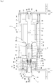
- Fig. 2 is a longitudinal sectional view of the bypass switch before the bypass switch is operated according to the first embodiment.
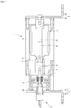
- Fig. 3 is a longitudinal sectional view of the bypass switch after the bypass switch is operated according to the first embodiment.
- Fig. 4 is a longitudinal section view showing a flow of current after the bypass switch is operated according to the first embodiment.
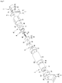
- Fig. 5 is an exploded perspective view of the bypass switch according to the first embodiment.
- Fig. 6 is an enlarged sectional view taken along line A-A shown in Fig. 3 .
- the bypass switch may include a casing 1, a vacuum interrupter 2, a moving pusher 3, a magnet 4, a drive source 5, a first fixing bus-bar 6, a second fixing bus-bar 7, and a multi-contactor 8.
- the casing 1 may form the external appearance of the bypass switch.
- the casing 1 may be configured as an assembly of a plurality of members.
- the casing 1 may include a conductive casing made of a conductive material such as aluminum and an insulative casing made of an insulative material such as a synthetic resin.
- the casing 1 may be configured as an assembly of at least one conductive casing and at least one insulative casing.
- the casing 1 may include a plurality of conductive casings.
- the insulative casing may be disposed between the plurality of conductive casings.
- a space 11 may be formed inside the casing 1.
- the vacuum interrupter 2, the moving pusher 3, the magnet 4, and the multi-contactor 8 may be provided in the space 11.
- a movable contact 21 may be disposed to be movable to a fixed contact 22.
- the vacuum interrupter 2 may be disposed inside the casing 1.
- the vacuum interrupter 2 may be disposed in the space 11 of the casing 1, and may be protected by the casing 1.
- An outer circumferential surface 2a of the vacuum interrupter 2 may face an inner surface 1a of the casing 1.
- the vacuum interrupter 2 may include an inner housing 23.
- the inner housing 23 may form the external appearance of the vacuum interrupter 2.
- the inner housing 23 may be a vacuum housing inside which an inner space 24 is formed.
- the movable contact 21 may be disposed to be movable in the inner housing 23.
- a movable contact through-hole 25 through which the movable contact 21 movably passes may be formed in the inner housing 23.
- the fixed contact 22 may be installed to be fixed to the inner housing 23.
- a fixed contact through-hole 26 through which the fixed contact 22 passes may be formed in the inner housing 23.
- the fixed contact through-hole 26 may be formed at a position at which it faces the movable contact through-hole 25.
- the inner housing 23 may be formed long in the length direction of the casing 1 inside the casing 1.
- the outer circumferential surface 2a of the inner housing 23 may become an outer circumferential surface of the vacuum interrupter 2.
- the outer circumferential surface 2a of the inner housing 23 may face the inner surface la of the casing 1.
- the moving pusher 3 may be connected to the movable contact 21 to move the movable contact 21.
- the movable contact 21 may be contacted with or separated from the fixed contact 22 when the moving pusher 3 is moved.
- the moving pusher 3 may locate the movable contact 21 such that the movable contact 21 is contacted with the fixed contact 22.
- the moving pusher 3 may locate the movable contact 21 such that the movable contact 21 is spaced apart from the fixed contact 22.
- the moving pusher 3 Before the drive source 5 is driven, the moving pusher 3, as shown in Fig. 2 , may be kept at a first position F at which it allows the movable contact 21 to be spaced apart from the fixed contact 22.
- the moving pusher 3, as shown in Fig. 3 may be moved at which it allows the movable contact 21 to be contacted with the fixed contact 22.
- the moving pusher 3 may be disposed between the drive source 5 and the movable contact 21 to push the movable contact 21 such that the movable contact 21 is contacted with the fixed contact 22 when the drive source 5 is driven.
- the moving pusher 3 may be a movable contact connector connected to the movable contact 21.
- the moving pusher 3 may constitute, together with the movable contact 21, a moving assembly.
- the moving pusher 3 may be configured with one member or an assembly of a plurality of members.
- the moving pusher 3 may include a moving part extending rod 31 connected to the movable contact 21.
- the moving part extending rod 31 may be connected to the movable contact 21 such that the whole or a portion of the moving part extending rod 31 is located at the outside of the vacuum interrupter 2.
- the moving part extending rod 31 may be integrally formed with the movable contact 21, or may be formed as a separate member from the movable contact 21 to be connected to the movable contact 21.
- a protruding part 31a protruding from the moving part extending rod 31 may be inserted into a protruding part insertion groove part 21a formed in the movable contact 21, and the moving part extending rod 31 and the movable contact 21 may be integrally moved.
- a protruding part insertion groove part may be formed in the moving part extending rod 31. It will be apparent that a protruding part protruding from the movable contact 21 may be inserted into the protruding part insertion groove part of the moving part extending rod 31.
- the moving pusher 3 may include a latch plate 32 connected to the moving part extending rod 31.
- the latch plate 32 may be located to be movable inside the casing 1.
- the latch plate 32 may be disposed to be movable between the vacuum interrupter 2 and the drive source 5.
- the latch plate 32 When an external force does not act on the latch plate 32, the latch plate 32, as shown in Fig. 2 , may be located close to the magnet 4 by the action of an attractive force of the magnet 4. Before the drive source 5 is driven, the latch plate 32, as shown in Fig. 2 , may be disposed to be adhered closely to a magnet holder 41 for fixing the magnet 4.
- the latch plate 32 may be configured with a single member or a plurality of members.
- the latch plate 32 may include a pin 33 to which a piston 51 of the drive source 5, which will be described later, applies an external force, and a plate body 34 facing at least one portion of the magnet 4.
- the plate body 34 may be made of a magnetic substance, and the attractive force of the magnet 4 may act on the plate body 34. If a separate external force does not act on the plate body 34, the plate body 34 may be pulled by the magnet 4 in the direction in which the magnet 4 is located.
- a pin insertion part 35 may be formed at one surface of the plate body 34, and an insertion hole 35a into which the pin 33 is inserted may be formed in the pin insertion part 35.
- a connecting part 36 connected to the moving part extending rod 31 may be formed at the opposite surface of the plate body 34.
- the plate body 34 may be formed as a plate in a disk shape.
- the pin insertion part 35 may protrude toward the drive source 5 from one surface of the plate, and the connecting part 36 may protrude toward the vacuum interrupter 2 from the opposite surface of the plate.
- a portion of the pin 33 may be inserted into the pin insertion part 35 of the plate body 34.
- the pin 33 may be disposed such that a portion of the pin 33, which is located at the outside of the pin insertion part 35 of the plate body 34, faces the piston 51 of the drive source 5.
- the pin insertion part 35 may protrude toward the drive source 5 from a surface facing the magnet 4 among both surfaces of the plate body 34.
- the connecting part 36 may protrude toward the moving part extending rod 31 from the opposite surface to the surface facing the magnet 4 among both the surfaces of the plate body 34.
- a connecting part insertion groove part 37 into which the connecting part 36 is inserted may be formed in the moving part extending rod 31, and the latch plate 32 may be fixed as the connecting part 36 formed at the plate body 34 is inserted into the connecting part insertion groove part 37 formed in the moving part extending rod 31.
- the latch plate 32 may constitute, together with the moving part extending rod 31, the moving pusher 3. When the drive source 5 is driven, the latch plate 32 may push the moving part extending rod 31, and the moving part extending rod 31 may push the movable contact 21.
- the magnet 4 may be disposed inside the casing 1 to allow an attractive force to act on the latch plate 32.
- the magnet 4 may attract the latch plate 32 by allowing a magnetic force to act on the latch plate 32, and therefore, the movable contact 21 and the fixed contact 22 may be spaced apart from each other.
- the magnet 4 may be formed in a ring or rod shape.
- the magnet 4 may be configured with one ring-shaped member or a plurality of rod-shaped members.
- the magnet holder 41 for fixing the magnet 4 may be disposed inside the casing 1.
- the magnet holder 41 may include an outer holder 42 facing an inner circumferential surface of the casing 1 and an inner holder 43 located at the inside of the outer holder 42.
- the magnet holder 41 may be configured as a magnetic body, particularly, a weak magnetic body.
- a space may be formed inside the outer holder 42, and the inner holder 43 may be located in the space of the outer holder 42 to be spaced apart from the outer holder 42.
- the magnet 4 may be inserted into a gap between the outer holder 42 and the inner holder 43 to fit between the outer holder 42 and the inner holder 43.
- a stopper by which the magnet 4 is held may be formed to protrude at the outer circumference of the inner holder 43.
- a through-hole 45 through which the pin insertion part 35 and the pin 33 are located to pass may be formed in the inner holder 43.
- the magnet holder 41 may be a magnet housing that surrounds the magnet 4 except its surface facing the plate body 34.
- the magnet holder 41 may further include a side holder 46 that faces the outer holder 42, the magnet 4, and the inner holder 43.
- the magnet 4 may be installed such that its position is fixed between the side holder 46 and the stopper 44.
- the side holder 46 may be fastened to at least one of the outer holder 42 and the inner holder 43 by a fastening member P1 such as a screw.
- a guide hole 47 for guiding at least one of the pin 33 and the piston 51 which will be described later may be formed in the side holder 46.
- the guide hole 47 may be formed to face the through-hole 45 of the inner holder 43.
- a portion of the pin 33 may be located in the guide hole 47.
- the side holder 46 may be a pin guide for guiding the pin 33.
- a drive source accommodating groove 46a in which a portion of the drive source 5 is inserted and accommodated may be formed in the side holder 46.
- the drive source accommodating groove 46a may be formed in a depressed shape in one of both surfaces of the side holder 46, which faces a second conductive casing 13 which will be described above.
- the bypass switch may further include a spring 48 for elastically supporting the latch plate 32 in the direction in which the movable contact 21 and the fixed contact 22 are contacted with each other.
- the spring 48 may support the plate body 34 in the direction of the vacuum interrupter 2 such that, when the movable contact 21 and the fixed contact 22 are contacted with each other, the contact state is maintained without separating the movable contact 21 from the fixed contact 22.
- the spring 48 may be configured as a coil spring having one end contacted with the plate body 34 and the other end contacted with the magnet holder 41.
- the spring 48 Before the drive source 5 is driven, the spring 48, as shown in Fig. 2 , may be compressed by being pressed by the latch plate 32 pulled by the magnet 4. If the drive source 5 is driven to push the latch plate 32 in the direction of the vacuum interrupter 2, the spring 48, as shown in Fig. 3 , may be elastically restored, and thus can prevent the latch plate 32 from returning in a direction opposite to that of the vacuum interrupter 2, i.e., the direction of the magnet 4.
- the spring 48 may be located at an outside of the pin insertion part 35 and an outside of the pin 33.
- the spring 48 may be located to surround the outside of the pin insertion part 35 and the outside of the pin 33.
- a spring seat part 49 may be formed in the magnet holder 41. Here, one side of the spring 48 is inserted and accommodated in the spring seat part 49, and the spring seat part 49 supports the spring 48.
- the spring seat part 49 may be formed in the inner holder 43.
- the spring seat part 40 may be formed in a depressed shape in one of both surfaces of the inner holder 43, which faces the plate body 34.
- a spring accommodating part 38 in which the other side of the spring 48 is inserted and accommodated may be formed in a depressed shape in the surface of the plate body 34, which faces the magnet 4.
- the drive source 5 is installed in the casing 1, and may push the moving pusher 3 to the position at which the movable contact 21 and the fixed contact 22 are contacted with each other.
- the drive source 5 preferably allows the moving pusher 3 to move at a high speed.
- the drive source 5 may be disposed to pass through the second conductive casing 13 which will be described later.
- the drive source 5 may include an explosive actuator. When the explosive actuator is driven, the piston 51 may apply, to the latch plate 32, an external force greater than the attractive force of the magnet 4.
- the explosive actuator 5 may be installed in the casing 1.
- the explosive actuator 5 may push at least one of the moving part extending rod 31 and the latch plate 32 such that the movable contact 21 and the fixed contact 22 are contacted with each other.
- the explosive actuator 5 may include the piston 51 and an inflator 52 for driving the piston 51 by spraying a gas to the piston 51.
- the inflator 52 may include a housing 52a inside which a space 53 is formed and a gas sprayer 52b for spraying the gas into the space 53 of the housing 52a.
- the piston 51 may be movably disposed in the inflator 52 to be moved at a high speed by the gas sprayed into the space 53.
- the piston 51 may advance into the guide hole 47 of the side holder 46 to push the pin 33 located in the guide hole 47 of the side holder 46 in the direction of the vacuum interrupter2.
- the inflator 52 sprays the gas into the space 53, and the piston 51 is pushed by the gas sprayed into the space 53 to push the latch plate 32 in the direction of the vacuum interrupter 2. Then, the moving part extending rod 31 is pushed by the latch plate 32 to allow the movable contact 21 to be contacted with the fixed contact 22. If a high-pressure gas is sprayed into the space 53 of the housing 52a, the piston 51 is rapidly moved by the high-pressure gas.
- the housing 52a may be disposed inside the casing 1.
- the gas sprayer 52b may be disposed to be exposed to the outside of the casing 1, and an electric wire 52c through which power for driving the gas sprayer 52b is applied may be connected to the gas sprayer 52b.
- the gas sprayer 52b may be a gas generator. If a firing signal is applied from the outside, the gas sprayer 52b is driven to spray a high-pressure gas into the space 53 of the housing 52a.
- the first fixing bus-bar 6 may be fixed to the casing 1.
- the first fixing bus-bar 6 is a fixed-contact-side bus-bar electrically connected to the fixed contact 22, and may be mounted to the casing 1 such that the position of the first fixing bus-bar 6 is fixed.
- the second fixing bus-bar 7 may be fixed to the casing 1 to be spaced apart from the first fixing bus-bar 6.
- the second fixing bus-bar 7 may be a movable-contact-side bus-bar electrically connected to the movable contact 21.
- the second fixing bus-bar 7 may be connected to the movable contact 21 through the second conductive casing 13 which will be described later, a multi-contactor supporter 12, the multi-contactor 8, and the moving part extending rod 31.
- the second fixing bus-bar 7 may be installed in the casing 1 to be located at the opposite side of the first fixing bus-bar 6.
- the first fixing bus-bar 6 and the second fixing bus-bar 7 may be spaced apart from each other with the casing 1 interposed therebetween.
- the first fixing bus-bar 6 may be disposed at one side of the casing 1
- the second fixing bus-bar 7 may be disposed at the other side of the casing 1.
- the first fixing bus-bar 6 and the second fixing bus bar 7 may be laterally spaced apart from each other with the casing 1 interposed therebetween.
- the second fixing bus-bar 7 may be located at a right side of the casing 1.
- the second fixing bus-bar 7 may be located at a left side of the casing 1.
- the casing 1 may be disposed between the first fixing bus-bar 6 and the second fixing bus-bar 7, and left and right surfaces of the casing 1 may be protected by the first fixing bus-bar 6 and the second fixing bus-bar 7.
- the bypass switch may include at least one moving part conductive member for conducting the multi-contactor 8 and the second fixing bus-bar 7.
- the bypass switch may include at least one fixing part conductive member for conducting the fixed contact 22 and the first fixing bus-bar 6.
- the bypass switch may include an insulative member disposed between the moving part conductive member and the fixing part conductive member to insulate between the moving part conductive member and the fixing part conductive member.
- the casing 1 may include a moving part conductive member for conducting the multi-contactor 8 and the second fixing bus-bar 7.
- the casing 1 may include a fixing part conductive member for conducting the fixed contact 22 and the first fixing bus-bar 6.
- the casing 1 includes at least one of the moving part conductive member and the fixing part conductive member, it is possible to minimize the number of parts of the bypass switch and to simplify the structure of the bypass switch.
- the casing 1 may include an insulative member for insulating between the moving part conductive member and the fixing part conductive member.
- an insulative member for insulating between the moving part conductive member and the fixing part conductive member.
- the casing 1 may include the multi-contactor supporter 12 for supporting the multi-contactor 8.
- the casing 1 may further include a first conductive casing 14 coupled to the fixed contact 21 and the first fixing bus-bar 6, and the second conductive casing 13 coupled to the multi-contactor supporter 12 and the second fixing bus-bar 7.
- Each of the multi-contactor supporter 12 and the second conductive casing 13 may be formed of a conductive material such as aluminum.
- the multi-contactor supporter 12 and the second conductive casing 13 may be moving part conductive members.
- the multi-contactor supporter 12 and the second conductive casing 13 may be configured in a single body. After the multi-contactor supporter 12 and the second conductive casing 13 are configured as separate members from each other, the multi-contactor supporter 12 and the second conductive casing 13 may be fastened to each other by a fastening member P2 such as a screw.
- a space in which the multi-contactor 8 is accommodated such that the position of the multi-contactor 8 is fixed may be formed inside the multi-contactor support 12.
- the multi-contactor supporter 12 may be formed in a hollow shape.
- the multi-contactor 8 is located between an inner circumferential surface of the multi-contactor supporter 12 and an outer circumferential surface of the moving part extending rod 31, and an inner circumferential surface of the multi-contactor 8 may be contacted with the outer circumferential surface of the moving part extending rod 31.
- a projection 12a by which the multi-contactor 8 is held may protrude from the inner circumference of the multi-contactor supporter 12.
- the projection 12a may protrude in a ring shape from one surface of the multi-contactor supporter 12, which faces the vacuum interrupter 2.
- the projection 12a may be formed to surround a portion of the movable contact 21, which is located at the outside of the inner housing 23 of the vacuum interrupter 2.
- the multi-contactor 8 may be accommodated such that one end of the multi-contactor 8 is contacted with the projection 12a.
- the position of the multi-contactor 8 may be maintained without being pushed by the moving part extending rod 31 in a state in which the multi-contactor 8 is held by the projection 12a.
- the second conductive casing 13 may include a hollow cylindrical body inside which a space is formed.
- the second conductive casing 13 may further include a plate body for blocking one surface of the hollow cylindrical body.
- the latch plate 32 may be movably located inside the second conductive casing 13.
- the magnet holder 41 may be disposed inside the second conductive casing 13 such that the position of the magnet holder 41 is fixed.
- the magnet holder 41 may be fixed to the second conductive casing 13 by the fastening member P1.
- the fastening member P1 may be fastened into a fastening hole formed in the outer holder 42 by sequentially passing through a fastening hole formed in the second conductive casing 13 and a fastening hole formed in the side holder 46.
- the second conductive casing 13 may serve as a magnet holder mounter in which the magnet holder 41 is mounted.
- a hollow cylindrical part 17 surrounding a portion of the drive source 5 may protrude from the second conductive casing 13.
- a drive source accommodating space in which a portion of the drive source 5 is accommodated may be formed inside the hollow cylindrical part 17.
- the hollow cylindrical part 17 may be formed to surround the housing 52a of the inflator 52 constituting the drive source 5.
- the drive source 5 may be installed such that the housing 52a is inserted into the hollow cylindrical part 17 of the second conductive casing 13. An end portion of the housing 52a of the inflator 52 may be inserted into the magnet holder 41, particularly, the drive source accommodating groove 46a of the side holder 46.
- a hollow cylindrical part through-hole 71 through which the hollow cylindrical part 17 passes may be formed in the second fixing bus-bar 7.
- the second fixing bus-bar 7 may include a contact plate body 72 contacted with the second conductive casing 13, and a bending part 73 bent from the contact plate body 72, the bending part 73 being parallel to the direction in which the drive source 5 protrudes to the outside.
- the hollow cylindrical part through-hole 71 may be formed in the contact plate body 72 of the second fixing bus-bar 7.
- One of both surfaces of the contact plate body 72 of the second fixing bus-bar 7, which faces an outer surface of the second conductive casing 13, may be surface-contacted with the outer surface of the second conductive casing 13.
- a circumferential surface of the hollow cylindrical part through-hole 71 formed in the contact plate body 72 of the second fixing bus-bar 7 may be surface-contacted to an outer circumferential surface of the hollow cylindrical part 17 of the second conductive casing 13.
- the first conductive casing 14 may be formed of a conductive material such as aluminum.
- the first conductive casing 14 may be a fixing part conductive member.
- the casing 1 may further include an insulative casing 15 disposed between the multi-contactor supporter 12 and the first conductive casing 14.
- the insulative casing 15 may be fastened to the multi-contactor supporter 12 by a fastening member such as a screw.
- Fastening member fastening holes into which the fastening member is inserted may be formed to face each other in the insulative casing 15 and the multi-contactor supporter 12.
- the insulative casing 15 may surround the vacuum interrupter 2 at the outside of the vacuum interrupter 2.
- the insulative casing 15 may be formed in the shape of a hollow cylindrical body, and a vacuum interrupter accommodating space 16 in which the vacuum interrupter 2 is accommodated may be formed inside the insulative casing 15.
- the vacuum interrupter 2 may be accommodated in the insulative casing 15 to be supported by the insulative casing 15, and the vacuum interrupter 2 is not exposed to the outside.
- the casing 1 does not surround the outer circumference of the vacuum interrupter 2, and a portion of the vacuum interrupter 2 is exposed to the outside, the possibility that the vacuum interrupter 2 will be broken may be high.
- the casing 1, particularly, the insulative casing 15 surrounds the outer circumference of the vacuum interrupter 2, the possibility that the vacuum interrupter 2 will be broken can be minimized.
- a fastening member through-hole 141 through which the fastening member P3 fastening the first conductive casing 14 to the insulative casing 15 passes may be formed in the first conductive casing 14.
- the first conductive casing 14 may be coupled to the insulative casing 15 through the fastening member through-hole 141.
- the fastening member P3 may be fastened into an insulative casing fastening hole 151 formed in the insulative casing 15 by passing through the fastening member through hole 141 formed in the first conductive casing 14.
- the first conductive casing 14 may be fastened to the fixed contact 22 through a fastening member P4 such as a screw.
- a central through-hole 142 through which the fastening member P4 passes may be formed in the first conductive casing 14.
- a fixed contact fastening hole 222 into which the fastening member P4 is fastened may be formed at a portion of the fixed contact 22, which protrudes to the outside of the inner housing 23.
- the fastening member P4 may be fastened into the fixed contact fastening hole 222 of the fixed contact 22 by passing through the central through-hole 142 of the first conductive casing 14.
- the first fixing bus-bar 6 may be disposed to cover the fastening member through-hole 141 and the fastening member P4.
- the fastening member P4 fastening the first conductive casing 14 to the insulative casing 15 may be covered by the first fixing bus-bar 6.
- An avoiding hole 61 for avoiding the fastening member P4 fastening the first conductive casing 14 to the fixed contact 22 may be formed in the first fixing bus-bar 6.
- the first fixing bus-bar 6 may include a contact plate body 62 contacted with the first conductive casing 14, and a bending part 63 bent from the contact plate body 62, the bending part 63 being bent in a direction opposite to that of the bending part 73 of the second fixing bus-bar 7.
- a surface of the contact plate body 62 of the first fixing bus-bar 6, which faces an outer surface of the first conductive casing 14, may be surface-contacted with the outer surface of the first conductive casing 14.
- the multi-contactor 8 may be disposed to be contacted with the moving pusher 3.
- the multi-contactor 8 may be disposed to be contacted with at least one of the moving part extending rod 31 and the latch plate 32.
- the multi-contactor 8 may be disposed to be contacted with the moving part extending rod 31 out of the moving part extending rod 31 and the latch plate 32.
- the multi-contactor 8 may be formed of a conductive material such as aluminum.
- the multi-contactor 8 may be contacted with the moving pusher 3 in a state in which the position of the multi-contactor 8 is fixed.
- the multi-contactor 8 may be disposed such that a plurality of points of the multi-contactor 8 are contacted with the moving pusher 3. A plurality of points of the multi-contactor 8 may be contacted with the moving pusher not only after the drive source 5 is driven but also before the drive source 5 is driven.
- the multi-contactor 8 may include a contact part 81 contacted with the moving pusher 3.
- the contact part 81 may be provided in plurality to the multi-contactor 8.
- a plurality of points of the multi-contactor 8 may be contacted with the plurality of contact parts 81. In this case, it is possible to improve reliability.
- the multi-contactor 8 may further include an outer body part 82 surrounding the outer circumference of the moving pusher 3.
- the contact part 81 may protrude from the outer body part 82 to be contacted with the moving pusher 3.
- the contact part 81 may protrude from the outer body part 82 to be contacted with the moving part extending rod 31.
- the outer body part 82 may be disposed to be spaced apart from the moving pusher 3.
- the outer body part 82 may be a non-contact part not contacted with the moving pusher 3.
- the entire inner circumference of the multi-contactor 8 is not contacted with the moving pusher 3, and only the plurality of contact parts 81 may be contacted with the moving pusher 3.
- a gap G may be formed between the outer body part 82 and the moving part extending rod 31.
- the moving part extending rod 31 is not surface-contacted with an inner circumferential surface of the outer body part 82, and may be rapidly moved when the explosive actuator 5 is driven.
- a plurality of contacts of the plurality of contact parts 81 are contacted with the moving part extending rod 31, so that it is possible to improve the reliability of electrical connection.
- the outer body part 82 may include a hollow cylindrical body surrounding a portion of the moving pusher 3.
- the hollow cylindrical body may be disposed to be spaced apart from the moving pusher 3 between the moving pusher 3 and the multi-contactor supporter 12.
- the hollow cylindrical body may have a bore spaced apart from an outer surface of the moving pusher.
- the hollow cylindrical body may surround a portion of the moving part extending rod 31 in the moving pusher 3.
- the hollow cylindrical body may be disposed to be spaced apart from the moving part extending rod 31 between the moving part extending rod 31 and the multi-contactor supporter 12.
- the hollow cylindrical body may have a bore spaced apart from the protruding part 31a of the moving part extending rod 31.
- the plurality of contact parts 81 may be integrally formed with the outer body part 82.
- Each of the plurality of contact parts 81 may be a protrusion protruding from the inner circumference of the hollow cylindrical body.
- the plurality of contact parts 81 may be spaced apart from each other in the circumferential direction of the hollow cylindrical body.
- the plurality of contact parts 81 may be formed long in a direction parallel to the length direction of the moving part extending rod 31.
- the drive source 5 may push the piston 51 in the direction of the vacuum interrupter 2.
- the inflator 52 may spray a high-pressure gas into the space 53 of the housing 52a, and the piston 51 may be move forward in the direction of the vacuum interrupter 2 by the high-pressure gas sprayed into the space 53 of the housing 52a.
- the piston 51 When the piston 51 is moved forward, the piston 51 may push the moving pusher 3 in the direction of the vacuum interrupter 2.
- the piston 51 may apply, to the latch plate 32, an external force greater than an attractive force of the magnet 4, and the latch plate 32 may become close to the vacuum interrupter 2 while being distant from the magnet 4.
- the latch plate 32 moved by the piston 51 may push the moving part extending rod 31.
- the moving part extending rod 31 may be slid inside the multi-contactor 8 in a state in which the moving part extending rod 31 is contacted with the plurality of contact parts 81 of the multi-contactor 8. When the moving part extending rod 31 is slid, the moving part extending rod 31 may be moved in the direction of the vacuum interrupter 2 while maintaining contact with the plurality of contact parts 81.
- the moving part extending rod 31 may be slid between the plurality of contact parts 81 while not being surface-contacted with the inner circumferential surface of the outer body part 82.
- the moving part extending rod 31 may be slid faster than when the moving part extending rod 31 is surface-contacted with the inner circumferential surface of the outer body part 82.
- the movable contact 21 connected to the moving part extending rod 31 may advance toward the fixed contact 22.
- the movable contact 21 may be contacted with the fixed contact 22.
- the spring 48 may push the latch plate 32 in the direction of the vacuum interrupter 2 while being elastically restored.
- the latch plate 32, the moving part extending rod 31, and the movable contact 21 are not returned to their original positions by a force with which the spring 48 pushes the latch plate 32, and the movable contact 21 may maintain contact with the fixed contact 22.
- the piston 51 When the spring 48 does not press the latch plate 32 in the direction of the vacuum interrupter 2, the piston 51 may be treated in the direction of the gas sprayer 52b by vibration, etc. after the explosive actuator 5 is fired. In this case, the gas in the housing 52a may be leaked, and the movable contact 21 may be separated from the fixed contact 22 due to the retreat of the piston 51 and the leakage of the gas.
- the fixed contact 22 and the multi-contactor 8 can be electrically conducted by the movable contact 21 and the moving part extending rod 31.
- the first fixing bus-bar 6 and the second fixing bus-bar 7, as shown in Fig. 4 can be electrically conducted through the first conductive casing 14, the fixed contact 22 and the movable contact 21, the moving part extending rod 31, the multi-contactor 8, the multi-contactor supporter 12, and the second conductive casing 13.
- the first conductive casing 14, the fixed contact 22 and the movable contact 21, the moving part extending rod 31, the multi-contactor 8, the multi-contactor supporter 12, and the second conductive casing 13, as shown in Fig. 4 can form a path through which the first fixing bus-bar 6 and the second fixing bus-bar 7 are electrically conducted.
- bypass switch can be short-circuited, and current can flow through the bypass switch.
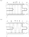
- Fig. 7 is an enlarged sectional view of a main part of a bypass switch according to a second embodiment.
- the shape of a contact part 81' is different from that of the contact part 81 of the first embodiment.
- other components except the contact part 81' are identical or similar to those of the first embodiment, and therefore, their detailed descriptions will be omitted.
- the contact part 81' of this embodiment may be formed in a ring shape along an inner circumferential surface 82a of an outer body part 82.
- the contact part 81' may be provided in plurality to the inner circumferential surface 82a of the body part 82, and the plurality of contact parts 81' may be spaced apart from each other in the length direction of the outer body part 82.
- An outer surface of a moving part extending rod 31 of the moving pusher 3 may be contacted with an inner circumferential surface of each of the plurality of contact parts 81'.
- a plurality of points of the moving part extending rod 31 of the moving pusher 3 may be contacted with a multi-contactor.
- Fig. 8 is an enlarged sectional view of a main part of a bypass switch according to a third embodiment.
- the shape of a contact part 81" is different from those of the contact part 81 of the first embodiment and the contact part 81' of the second embodiment.
- other components except the contact part 81" are identical or similar to those of the first embodiment and the second embodiment, and therefore, their detailed descriptions will be omitted.
- the contact part 81" of this embodiment may be configured as a spiral contact part spirally protruding along the inner circumference of an outer body part 82, and the spiral contact part may be contacted with a moving pusher 3.
- An outer surface of a moving part extending rod 31 of the moving pusher 3 may be continuously contacted along the contact part 81".
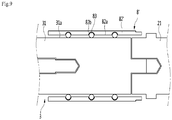
- Fig. 9 is an enlarged sectional view of a main part of a bypass switch according to a fourth embodiment.
- the configuration of a multi-contactor 8' is different from those of the first to third embodiments.
- other components except the multi-contactor 8' are identical or similar to those of the first to third embodiments, and therefore, their detailed descriptions will be omitted.
- the multi-contactor 8' may include an outer body 82' having a ball insertion groove 82b formed in an inner circumferential surface 82a thereof, and a ball 83 inserted into the ball insertion groove 82b, the ball 83 being contacted with an outer surface of a moving pusher 3.
- the outer body 82' is a component corresponding to the outer body part 82 of the first embodiment.
- the configuration of the outer body 82' except that the ball insertion groove 82b is formed in the inner circumferential surface 82a is identical to that of the outer body part 82 of the first embodiment, and therefore, its detailed description will be omitted.
- the ball 83 may be located to be rollable in the ball insertion groove 82b. When the moving pusher 3 is moved, the ball 83 may roll along the moving pusher 3 in a state in which the ball 83 is contacted with the outer surface of the moving pusher 3.
- a plurality of ball insertion grooves 82b may be formed in the outer body 82'.
- the multi-contactor 8' may include a plurality of balls 83, and the balls 83 and the ball insertion grooves 82b may be provided to correspond one by one.
- the plurality of ball insertion grooves 82b may be spaced apart from each other in the length direction of the outer body 82'.
- the plurality of balls 83 may be contacted with the moving pusher 3 in a state in which the plurality of balls 83 are disposed to be spaced apart from each other in the length direction of the outer body 82'.
- the plurality of ball insertion grooves 82b may be spaced apart from each other in the circumferential direction of the outer body 82'.
- the plurality of balls 83 may be contacted with the moving pusher 3 in a state in which the plurality of balls 83 are disposed to be spaced apart from each other in the circumferential direction of the outer body 82'.
- An outer surface of a moving part extending rod 31 of the moving pusher 3 may be disposed to be contacted with the plurality of balls 83.
- Current flowing in the bypass switch can flow in the outer body 82' through the moving part extending rod 31 and the plurality of balls 83.
Landscapes
- Engineering & Computer Science (AREA)
- Power Engineering (AREA)
- High-Tension Arc-Extinguishing Switches Without Spraying Means (AREA)
- Push-Button Switches (AREA)
- Gas-Insulated Switchgears (AREA)
- Driving Mechanisms And Operating Circuits Of Arc-Extinguishing High-Tension Switches (AREA)
Applications Claiming Priority (1)
| Application Number | Priority Date | Filing Date | Title |
|---|---|---|---|
| KR1020160018051A KR101870016B1 (ko) | 2016-02-16 | 2016-02-16 | 바이패스 스위치 |
Publications (3)
| Publication Number | Publication Date |
|---|---|
| EP3208825A1 EP3208825A1 (en) | 2017-08-23 |
| EP3208825B1 EP3208825B1 (en) | 2019-01-09 |
| EP3208825B2 true EP3208825B2 (en) | 2021-12-29 |
Family
ID=56682038
Family Applications (1)
| Application Number | Title | Priority Date | Filing Date |
|---|---|---|---|
| EP16183762.0A Active EP3208825B2 (en) | 2016-02-16 | 2016-08-11 | Bypass switch |
Country Status (6)
| Country | Link |
|---|---|
| US (1) | US9953779B2 (ko) |
| EP (1) | EP3208825B2 (ko) |
| JP (1) | JP6378270B2 (ko) |
| KR (1) | KR101870016B1 (ko) |
| CN (1) | CN107086164B (ko) |
| ES (1) | ES2712667T5 (ko) |
Families Citing this family (13)
| Publication number | Priority date | Publication date | Assignee | Title |
|---|---|---|---|---|
| US10566160B2 (en) * | 2015-05-18 | 2020-02-18 | Gigavac, Llc | Passive triggering mechanisms for use with switching devices incorporating pyrotechnic features |
| US11239038B2 (en) * | 2015-05-18 | 2022-02-01 | Gigavac, Llc | Mechanical fuse device |
| US10281248B2 (en) * | 2015-11-11 | 2019-05-07 | Northrop Grumman Innovation Systems, Inc. | Gas generators, launch tube assemblies including gas generators, and related systems and methods |
| DE102017217166A1 (de) * | 2017-09-27 | 2019-03-28 | Siemens Aktiengesellschaft | Anordnung und Verfahren zum Dämpfen des Kontaktprellens bei Hochspannungsleistungsschaltern |
| KR20190002819U (ko) | 2018-05-03 | 2019-11-13 | 엘에스산전 주식회사 | 바이패스 스위치 |
| EP3814216B1 (en) * | 2018-05-17 | 2024-05-15 | Adams Rite Aerospace Inc. | Pyrotechnic latch actuator responsive to a decompression detection system and method |
| US11276535B2 (en) * | 2018-08-28 | 2022-03-15 | Gigavac, Llc | Passive triggering mechanisms for use with switching devices incorporating pyrotechnic features |
| KR102190066B1 (ko) * | 2019-05-24 | 2020-12-11 | 엘에스일렉트릭(주) | 바이패스 스위치 |
| KR102190065B1 (ko) * | 2019-05-24 | 2020-12-11 | 엘에스일렉트릭(주) | 바이패스 스위치 |
| US20220246376A1 (en) * | 2019-05-24 | 2022-08-04 | Ls Electric Co., Ltd. | Bypass switch |
| US10825625B1 (en) * | 2019-06-07 | 2020-11-03 | Smart Wires Inc. | Kinetic actuator for vacuum interrupter |
| US11443910B2 (en) | 2019-09-27 | 2022-09-13 | Gigavac, Llc | Contact levitation triggering mechanisms for use with switching devices incorporating pyrotechnic features |
| CN111539170B (zh) * | 2020-04-09 | 2023-04-25 | 南昌工程学院 | 一种statcom冗余子模块开关暂态建模方法 |
Citations (6)
| Publication number | Priority date | Publication date | Assignee | Title |
|---|---|---|---|---|
| EP0665568A1 (en) † | 1994-01-27 | 1995-08-02 | G & H Technology, Inc. | Cell bypass switch |
| US20030231452A1 (en) † | 2002-06-14 | 2003-12-18 | Engelbert Hetzmannseder | Vacuum arc interrupter actuated by a gas generated driving force |
| EP2034503A1 (en) † | 2007-09-05 | 2009-03-11 | ABB Technology AG | Low-voltage, medium-voltage or high-voltage switchgear assembly having a short-circuiting system |
| EP2073229A1 (fr) † | 2007-12-18 | 2009-06-24 | Schneider Electric Industries SAS | Court-circuiteur pyrotechnique à contacts électrique auto-serrant et ensemble de protection contre les arcs internes comportant un tel court-circuiteur |
| US20100118453A1 (en) † | 2007-04-16 | 2010-05-13 | Siemens Aktiengesellschaft | Apparatus for Protection of Converter Modules |
| US20110226740A1 (en) † | 2008-11-26 | 2011-09-22 | Siemens Aktiengesellschaft | Vacuum switch having fixed rail terminals on both sides |
Family Cites Families (27)
| Publication number | Priority date | Publication date | Assignee | Title |
|---|---|---|---|---|
| JPS52115856U (ko) | 1976-02-27 | 1977-09-02 | ||
| JPS583791B2 (ja) | 1976-06-14 | 1983-01-22 | 新東工業株式会社 | 竪割無枠鋳型における鋳造品の取り出し移し替え方法およびその装置 |
| JPS5477974U (ko) | 1977-11-14 | 1979-06-02 | ||
| US4396969A (en) * | 1981-11-27 | 1983-08-02 | Porta Systems Corp. | Gas tube protector module |
| JPH0832132B2 (ja) | 1984-11-09 | 1996-03-27 | 日新電機株式会社 | 瞬時電圧低下補償装置 |
| JPS6323743U (ko) * | 1986-07-30 | 1988-02-17 | ||
| JPH01279528A (ja) | 1988-05-02 | 1989-11-09 | Hitachi Ltd | 高速度真空遮断装置 |
| JPH02281521A (ja) * | 1989-03-16 | 1990-11-19 | Sprecher Energ Ag | 多極真空遮断器および多極真空遮断器のための絶縁支持枠 |
| DE4021945C2 (de) * | 1990-07-10 | 1999-12-30 | Alstom Sachsenwerk Gmbh | Schaltvorrichtung zur Unterbrechung von Fehlerströmen |
| DE4133091C2 (de) * | 1991-09-30 | 1995-06-01 | Siemens Ag | Vakuumschalter mit einer Antriebsvorrichtung und einer Polantriebseinheit |
| JPH0652761A (ja) * | 1992-08-01 | 1994-02-25 | Mitsubishi Electric Corp | 開閉器 |
| DE9401655U1 (de) | 1993-06-18 | 1994-11-03 | Siemens Ag | Vakuumschaltröhre mit ringförigem Isolator |
| US5808258A (en) | 1995-12-26 | 1998-09-15 | Amerace Corporation | Encapsulated high voltage vacuum switches |
| DE69839358T2 (de) * | 1997-09-29 | 2009-06-04 | Mitsubishi Denki K.K. | Schaltvorrichtung |
| US6326872B1 (en) * | 2000-05-09 | 2001-12-04 | Eaton Corporation | Power circuit breaker with air gap between molded insulative casing and grounded barrier insulating operating mechanism |
| US6657150B1 (en) * | 2002-06-14 | 2003-12-02 | Eaton Corporation | Shorting switch and system to eliminate arcing faults in power distribution equipment |
| JP2005038630A (ja) * | 2003-07-15 | 2005-02-10 | Toshiba Corp | 真空遮断装置 |
| JP4458858B2 (ja) * | 2004-01-07 | 2010-04-28 | 三菱電機株式会社 | 電磁操作機構の手動開放装置 |
| US6930271B1 (en) * | 2004-08-13 | 2005-08-16 | Eaton Corporation | Circuit interrupter including linear actuator and manual pivot member |
| US7538454B2 (en) * | 2005-06-30 | 2009-05-26 | Honeywell International Inc. | Leakage current shunt in an electrical power distribution system utilizing solid state relays |
| CN200990333Y (zh) * | 2006-07-31 | 2007-12-12 | 厦门华电开关有限公司 | 一种真空断路器极柱 |
| JP4946920B2 (ja) * | 2008-03-03 | 2012-06-06 | 三菱電機株式会社 | 真空開閉器 |
| JP5338477B2 (ja) | 2009-05-25 | 2013-11-13 | 株式会社明電舎 | 真空遮断器 |
| CN101976626A (zh) * | 2010-11-09 | 2011-02-16 | 常州市明及电气技术开发有限公司 | 真空灭弧室的结构 |
| JP5199498B2 (ja) * | 2011-04-27 | 2013-05-15 | 株式会社日立製作所 | 電気接点用グリース及び摺動通電構造、電力用開閉機器、真空遮断器、真空絶縁スイッチギヤ、並びに真空絶縁スイッチギヤの組立方法 |
| KR101613812B1 (ko) | 2015-01-12 | 2016-04-19 | 엘에스산전 주식회사 | 초고압 직류 송전의 바이패스 스위치 |
| CN104851740B (zh) * | 2015-05-28 | 2017-06-30 | 东南大学 | 一种带辅助线圈的高压真空断路器用长行程永磁操动机构 |
-
2016
- 2016-02-16 KR KR1020160018051A patent/KR101870016B1/ko active IP Right Grant
- 2016-08-11 ES ES16183762T patent/ES2712667T5/es active Active
- 2016-08-11 EP EP16183762.0A patent/EP3208825B2/en active Active
- 2016-08-18 US US15/240,862 patent/US9953779B2/en active Active
- 2016-09-09 JP JP2016176455A patent/JP6378270B2/ja active Active
-
2017
- 2017-02-13 CN CN201710076171.6A patent/CN107086164B/zh active Active
Patent Citations (6)
| Publication number | Priority date | Publication date | Assignee | Title |
|---|---|---|---|---|
| EP0665568A1 (en) † | 1994-01-27 | 1995-08-02 | G & H Technology, Inc. | Cell bypass switch |
| US20030231452A1 (en) † | 2002-06-14 | 2003-12-18 | Engelbert Hetzmannseder | Vacuum arc interrupter actuated by a gas generated driving force |
| US20100118453A1 (en) † | 2007-04-16 | 2010-05-13 | Siemens Aktiengesellschaft | Apparatus for Protection of Converter Modules |
| EP2034503A1 (en) † | 2007-09-05 | 2009-03-11 | ABB Technology AG | Low-voltage, medium-voltage or high-voltage switchgear assembly having a short-circuiting system |
| EP2073229A1 (fr) † | 2007-12-18 | 2009-06-24 | Schneider Electric Industries SAS | Court-circuiteur pyrotechnique à contacts électrique auto-serrant et ensemble de protection contre les arcs internes comportant un tel court-circuiteur |
| US20110226740A1 (en) † | 2008-11-26 | 2011-09-22 | Siemens Aktiengesellschaft | Vacuum switch having fixed rail terminals on both sides |
Non-Patent Citations (2)
| Title |
|---|
| UFES ULTRA-FAST EARTHING SWITCH, 2015, XP055650617 † |
| UFES ULTRASCHNELLER ERDUNGSSCHALTER, September 2012 (2012-09-01), XP055650615 † |
Also Published As
| Publication number | Publication date |
|---|---|
| CN107086164B (zh) | 2020-03-27 |
| ES2712667T5 (es) | 2022-04-20 |
| CN107086164A (zh) | 2017-08-22 |
| US9953779B2 (en) | 2018-04-24 |
| EP3208825A1 (en) | 2017-08-23 |
| KR20170096539A (ko) | 2017-08-24 |
| US20170236663A1 (en) | 2017-08-17 |
| KR101870016B1 (ko) | 2018-07-23 |
| ES2712667T3 (es) | 2019-05-14 |
| EP3208825B1 (en) | 2019-01-09 |
| JP2017147216A (ja) | 2017-08-24 |
| JP6378270B2 (ja) | 2018-08-22 |
Similar Documents
| Publication | Publication Date | Title |
|---|---|---|
| EP3208825B2 (en) | Bypass switch | |
| US7942684B1 (en) | Connector device, receiving connector, and inserting connector | |
| US9659727B2 (en) | Switch | |
| KR101704807B1 (ko) | 차단기용 전자반발 조작기 | |
| ZA200508667B (en) | Vacuum circuit breaker | |
| EP2562777B1 (en) | Dual structured contact for switchgear and switchgear having the same | |
| US20140048514A1 (en) | Contact assembly and vacuum switch including the same | |
| CN104953522A (zh) | 电气安装设备的暗装嵌件 | |
| US8294540B2 (en) | Relay with multiple contacts | |
| KR101654949B1 (ko) | 복수의 어레스터 칼럼을 포함하는 어레스터 전류 경로를 갖는 서지 어레스터 장치 | |
| US10679807B2 (en) | Power breaking device | |
| US11657996B2 (en) | Relay contactor dual linear actuator module system | |
| EP3979286A1 (en) | Bypass switch | |
| KR102190065B1 (ko) | 바이패스 스위치 | |
| KR102190066B1 (ko) | 바이패스 스위치 | |
| KR20190002819U (ko) | 바이패스 스위치 | |
| CN109671596B (zh) | 塑壳断路器 | |
| EP3817163A1 (en) | Conductor assembly for a power distribution system | |
| EP2482295B1 (en) | Relay with multiple contacts | |
| EP3355411B1 (en) | Bushing adapter and bushing with superior mechanical characteristics | |
| KR20170117826A (ko) | 가스절연개폐기의 단로기 |
Legal Events
| Date | Code | Title | Description |
|---|---|---|---|
| PUAI | Public reference made under article 153(3) epc to a published international application that has entered the european phase |
Free format text: ORIGINAL CODE: 0009012 |
|
| STAA | Information on the status of an ep patent application or granted ep patent |
Free format text: STATUS: THE APPLICATION HAS BEEN PUBLISHED |
|
| AK | Designated contracting states |
Kind code of ref document: A1 Designated state(s): AL AT BE BG CH CY CZ DE DK EE ES FI FR GB GR HR HU IE IS IT LI LT LU LV MC MK MT NL NO PL PT RO RS SE SI SK SM TR |
|
| AX | Request for extension of the european patent |
Extension state: BA ME |
|
| STAA | Information on the status of an ep patent application or granted ep patent |
Free format text: STATUS: REQUEST FOR EXAMINATION WAS MADE |
|
| 17P | Request for examination filed |
Effective date: 20180212 |
|
| RBV | Designated contracting states (corrected) |
Designated state(s): AL AT BE BG CH CY CZ DE DK EE ES FI FR GB GR HR HU IE IS IT LI LT LU LV MC MK MT NL NO PL PT RO RS SE SI SK SM TR |
|
| GRAP | Despatch of communication of intention to grant a patent |
Free format text: ORIGINAL CODE: EPIDOSNIGR1 |
|
| STAA | Information on the status of an ep patent application or granted ep patent |
Free format text: STATUS: GRANT OF PATENT IS INTENDED |
|
| RIC1 | Information provided on ipc code assigned before grant |
Ipc: H01H 33/662 20060101ALI20180706BHEP Ipc: H01H 79/00 20060101AFI20180706BHEP Ipc: H01H 39/00 20060101ALI20180706BHEP Ipc: H01H 33/666 20060101ALI20180706BHEP Ipc: H01R 13/187 20060101ALI20180706BHEP Ipc: H02M 1/32 20070101ALI20180706BHEP |
|
| INTG | Intention to grant announced |
Effective date: 20180801 |
|
| GRAS | Grant fee paid |
Free format text: ORIGINAL CODE: EPIDOSNIGR3 |
|
| GRAA | (expected) grant |
Free format text: ORIGINAL CODE: 0009210 |
|
| STAA | Information on the status of an ep patent application or granted ep patent |
Free format text: STATUS: THE PATENT HAS BEEN GRANTED |
|
| AK | Designated contracting states |
Kind code of ref document: B1 Designated state(s): AL AT BE BG CH CY CZ DE DK EE ES FI FR GB GR HR HU IE IS IT LI LT LU LV MC MK MT NL NO PL PT RO RS SE SI SK SM TR |
|
| REG | Reference to a national code |
Ref country code: GB Ref legal event code: FG4D |
|
| REG | Reference to a national code |
Ref country code: CH Ref legal event code: EP Ref country code: AT Ref legal event code: REF Ref document number: 1088360 Country of ref document: AT Kind code of ref document: T Effective date: 20190115 |
|
| REG | Reference to a national code |
Ref country code: DE Ref legal event code: R096 Ref document number: 602016009138 Country of ref document: DE |
|
| REG | Reference to a national code |
Ref country code: IE Ref legal event code: FG4D |
|
| REG | Reference to a national code |
Ref country code: ES Ref legal event code: FG2A Ref document number: 2712667 Country of ref document: ES Kind code of ref document: T3 Effective date: 20190514 |
|
| REG | Reference to a national code |
Ref country code: NL Ref legal event code: MP Effective date: 20190109 |
|
| REG | Reference to a national code |
Ref country code: LT Ref legal event code: MG4D |
|
| PG25 | Lapsed in a contracting state [announced via postgrant information from national office to epo] |
Ref country code: NL Free format text: LAPSE BECAUSE OF FAILURE TO SUBMIT A TRANSLATION OF THE DESCRIPTION OR TO PAY THE FEE WITHIN THE PRESCRIBED TIME-LIMIT Effective date: 20190109 |
|
| REG | Reference to a national code |
Ref country code: AT Ref legal event code: MK05 Ref document number: 1088360 Country of ref document: AT Kind code of ref document: T Effective date: 20190109 |
|
| PG25 | Lapsed in a contracting state [announced via postgrant information from national office to epo] |
Ref country code: PL Free format text: LAPSE BECAUSE OF FAILURE TO SUBMIT A TRANSLATION OF THE DESCRIPTION OR TO PAY THE FEE WITHIN THE PRESCRIBED TIME-LIMIT Effective date: 20190109 Ref country code: FI Free format text: LAPSE BECAUSE OF FAILURE TO SUBMIT A TRANSLATION OF THE DESCRIPTION OR TO PAY THE FEE WITHIN THE PRESCRIBED TIME-LIMIT Effective date: 20190109 Ref country code: LT Free format text: LAPSE BECAUSE OF FAILURE TO SUBMIT A TRANSLATION OF THE DESCRIPTION OR TO PAY THE FEE WITHIN THE PRESCRIBED TIME-LIMIT Effective date: 20190109 Ref country code: SE Free format text: LAPSE BECAUSE OF FAILURE TO SUBMIT A TRANSLATION OF THE DESCRIPTION OR TO PAY THE FEE WITHIN THE PRESCRIBED TIME-LIMIT Effective date: 20190109 Ref country code: NO Free format text: LAPSE BECAUSE OF FAILURE TO SUBMIT A TRANSLATION OF THE DESCRIPTION OR TO PAY THE FEE WITHIN THE PRESCRIBED TIME-LIMIT Effective date: 20190409 Ref country code: PT Free format text: LAPSE BECAUSE OF FAILURE TO SUBMIT A TRANSLATION OF THE DESCRIPTION OR TO PAY THE FEE WITHIN THE PRESCRIBED TIME-LIMIT Effective date: 20190509 |
|
| PG25 | Lapsed in a contracting state [announced via postgrant information from national office to epo] |
Ref country code: GR Free format text: LAPSE BECAUSE OF FAILURE TO SUBMIT A TRANSLATION OF THE DESCRIPTION OR TO PAY THE FEE WITHIN THE PRESCRIBED TIME-LIMIT Effective date: 20190410 Ref country code: BG Free format text: LAPSE BECAUSE OF FAILURE TO SUBMIT A TRANSLATION OF THE DESCRIPTION OR TO PAY THE FEE WITHIN THE PRESCRIBED TIME-LIMIT Effective date: 20190409 Ref country code: RS Free format text: LAPSE BECAUSE OF FAILURE TO SUBMIT A TRANSLATION OF THE DESCRIPTION OR TO PAY THE FEE WITHIN THE PRESCRIBED TIME-LIMIT Effective date: 20190109 Ref country code: HR Free format text: LAPSE BECAUSE OF FAILURE TO SUBMIT A TRANSLATION OF THE DESCRIPTION OR TO PAY THE FEE WITHIN THE PRESCRIBED TIME-LIMIT Effective date: 20190109 Ref country code: LV Free format text: LAPSE BECAUSE OF FAILURE TO SUBMIT A TRANSLATION OF THE DESCRIPTION OR TO PAY THE FEE WITHIN THE PRESCRIBED TIME-LIMIT Effective date: 20190109 Ref country code: IS Free format text: LAPSE BECAUSE OF FAILURE TO SUBMIT A TRANSLATION OF THE DESCRIPTION OR TO PAY THE FEE WITHIN THE PRESCRIBED TIME-LIMIT Effective date: 20190509 |
|
| REG | Reference to a national code |
Ref country code: DE Ref legal event code: R026 Ref document number: 602016009138 Country of ref document: DE |
|
| PLBI | Opposition filed |
Free format text: ORIGINAL CODE: 0009260 |
|
| PLAX | Notice of opposition and request to file observation + time limit sent |
Free format text: ORIGINAL CODE: EPIDOSNOBS2 |
|
| PG25 | Lapsed in a contracting state [announced via postgrant information from national office to epo] |
Ref country code: AT Free format text: LAPSE BECAUSE OF FAILURE TO SUBMIT A TRANSLATION OF THE DESCRIPTION OR TO PAY THE FEE WITHIN THE PRESCRIBED TIME-LIMIT Effective date: 20190109 Ref country code: EE Free format text: LAPSE BECAUSE OF FAILURE TO SUBMIT A TRANSLATION OF THE DESCRIPTION OR TO PAY THE FEE WITHIN THE PRESCRIBED TIME-LIMIT Effective date: 20190109 Ref country code: AL Free format text: LAPSE BECAUSE OF FAILURE TO SUBMIT A TRANSLATION OF THE DESCRIPTION OR TO PAY THE FEE WITHIN THE PRESCRIBED TIME-LIMIT Effective date: 20190109 Ref country code: DK Free format text: LAPSE BECAUSE OF FAILURE TO SUBMIT A TRANSLATION OF THE DESCRIPTION OR TO PAY THE FEE WITHIN THE PRESCRIBED TIME-LIMIT Effective date: 20190109 Ref country code: SK Free format text: LAPSE BECAUSE OF FAILURE TO SUBMIT A TRANSLATION OF THE DESCRIPTION OR TO PAY THE FEE WITHIN THE PRESCRIBED TIME-LIMIT Effective date: 20190109 Ref country code: RO Free format text: LAPSE BECAUSE OF FAILURE TO SUBMIT A TRANSLATION OF THE DESCRIPTION OR TO PAY THE FEE WITHIN THE PRESCRIBED TIME-LIMIT Effective date: 20190109 Ref country code: CZ Free format text: LAPSE BECAUSE OF FAILURE TO SUBMIT A TRANSLATION OF THE DESCRIPTION OR TO PAY THE FEE WITHIN THE PRESCRIBED TIME-LIMIT Effective date: 20190109 |
|
| 26 | Opposition filed |
Opponent name: ABB SCHWEIZ AG Effective date: 20191007 |
|
| PG25 | Lapsed in a contracting state [announced via postgrant information from national office to epo] |
Ref country code: SI Free format text: LAPSE BECAUSE OF FAILURE TO SUBMIT A TRANSLATION OF THE DESCRIPTION OR TO PAY THE FEE WITHIN THE PRESCRIBED TIME-LIMIT Effective date: 20190109 |
|
| PG25 | Lapsed in a contracting state [announced via postgrant information from national office to epo] |
Ref country code: TR Free format text: LAPSE BECAUSE OF FAILURE TO SUBMIT A TRANSLATION OF THE DESCRIPTION OR TO PAY THE FEE WITHIN THE PRESCRIBED TIME-LIMIT Effective date: 20190109 |
|
| PLBB | Reply of patent proprietor to notice(s) of opposition received |
Free format text: ORIGINAL CODE: EPIDOSNOBS3 |
|
| PG25 | Lapsed in a contracting state [announced via postgrant information from national office to epo] |
Ref country code: LU Free format text: LAPSE BECAUSE OF NON-PAYMENT OF DUE FEES Effective date: 20190811 Ref country code: LI Free format text: LAPSE BECAUSE OF NON-PAYMENT OF DUE FEES Effective date: 20190831 Ref country code: MC Free format text: LAPSE BECAUSE OF FAILURE TO SUBMIT A TRANSLATION OF THE DESCRIPTION OR TO PAY THE FEE WITHIN THE PRESCRIBED TIME-LIMIT Effective date: 20190109 Ref country code: CH Free format text: LAPSE BECAUSE OF NON-PAYMENT OF DUE FEES Effective date: 20190831 |
|
| REG | Reference to a national code |
Ref country code: BE Ref legal event code: MM Effective date: 20190831 |
|
| PG25 | Lapsed in a contracting state [announced via postgrant information from national office to epo] |
Ref country code: IE Free format text: LAPSE BECAUSE OF NON-PAYMENT OF DUE FEES Effective date: 20190811 |
|
| PG25 | Lapsed in a contracting state [announced via postgrant information from national office to epo] |
Ref country code: BE Free format text: LAPSE BECAUSE OF NON-PAYMENT OF DUE FEES Effective date: 20190831 |
|
| PG25 | Lapsed in a contracting state [announced via postgrant information from national office to epo] |
Ref country code: CY Free format text: LAPSE BECAUSE OF FAILURE TO SUBMIT A TRANSLATION OF THE DESCRIPTION OR TO PAY THE FEE WITHIN THE PRESCRIBED TIME-LIMIT Effective date: 20190109 |
|
| PG25 | Lapsed in a contracting state [announced via postgrant information from national office to epo] |
Ref country code: SM Free format text: LAPSE BECAUSE OF FAILURE TO SUBMIT A TRANSLATION OF THE DESCRIPTION OR TO PAY THE FEE WITHIN THE PRESCRIBED TIME-LIMIT Effective date: 20190109 |
|
| PG25 | Lapsed in a contracting state [announced via postgrant information from national office to epo] |
Ref country code: HU Free format text: LAPSE BECAUSE OF FAILURE TO SUBMIT A TRANSLATION OF THE DESCRIPTION OR TO PAY THE FEE WITHIN THE PRESCRIBED TIME-LIMIT; INVALID AB INITIO Effective date: 20160811 Ref country code: MT Free format text: LAPSE BECAUSE OF FAILURE TO SUBMIT A TRANSLATION OF THE DESCRIPTION OR TO PAY THE FEE WITHIN THE PRESCRIBED TIME-LIMIT Effective date: 20190109 |
|
| PUAH | Patent maintained in amended form |
Free format text: ORIGINAL CODE: 0009272 |
|
| STAA | Information on the status of an ep patent application or granted ep patent |
Free format text: STATUS: PATENT MAINTAINED AS AMENDED |
|
| 27A | Patent maintained in amended form |
Effective date: 20211229 |
|
| AK | Designated contracting states |
Kind code of ref document: B2 Designated state(s): AL AT BE BG CH CY CZ DE DK EE ES FI FR GB GR HR HU IE IS IT LI LT LU LV MC MK MT NL NO PL PT RO RS SE SI SK SM TR |
|
| REG | Reference to a national code |
Ref country code: DE Ref legal event code: R102 Ref document number: 602016009138 Country of ref document: DE |
|
| REG | Reference to a national code |
Ref country code: ES Ref legal event code: DC2A Ref document number: 2712667 Country of ref document: ES Kind code of ref document: T5 Effective date: 20220420 |
|
| PG25 | Lapsed in a contracting state [announced via postgrant information from national office to epo] |
Ref country code: MK Free format text: LAPSE BECAUSE OF FAILURE TO SUBMIT A TRANSLATION OF THE DESCRIPTION OR TO PAY THE FEE WITHIN THE PRESCRIBED TIME-LIMIT Effective date: 20190109 |
|
| PGFP | Annual fee paid to national office [announced via postgrant information from national office to epo] |
Ref country code: IT Payment date: 20230608 Year of fee payment: 8 Ref country code: FR Payment date: 20230609 Year of fee payment: 8 |
|
| P01 | Opt-out of the competence of the unified patent court (upc) registered |
Effective date: 20230625 |
|
| PGFP | Annual fee paid to national office [announced via postgrant information from national office to epo] |
Ref country code: GB Payment date: 20230607 Year of fee payment: 8 Ref country code: ES Payment date: 20230908 Year of fee payment: 8 |
|
| PGFP | Annual fee paid to national office [announced via postgrant information from national office to epo] |
Ref country code: DE Payment date: 20230607 Year of fee payment: 8 |