EP3208367B1 - Garnkühler - Google Patents
Garnkühler Download PDFInfo
- Publication number
- EP3208367B1 EP3208367B1 EP17154570.0A EP17154570A EP3208367B1 EP 3208367 B1 EP3208367 B1 EP 3208367B1 EP 17154570 A EP17154570 A EP 17154570A EP 3208367 B1 EP3208367 B1 EP 3208367B1
- Authority
- EP
- European Patent Office
- Prior art keywords
- passage
- yarn
- bulging
- enlarged portion
- flow adjustment
- Prior art date
- Legal status (The legal status is an assumption and is not a legal conclusion. Google has not performed a legal analysis and makes no representation as to the accuracy of the status listed.)
- Active
Links
Images




Classifications
-
- D—TEXTILES; PAPER
- D01—NATURAL OR MAN-MADE THREADS OR FIBRES; SPINNING
- D01D—MECHANICAL METHODS OR APPARATUS IN THE MANUFACTURE OF ARTIFICIAL FILAMENTS, THREADS, FIBRES, BRISTLES OR RIBBONS
- D01D5/00—Formation of filaments, threads, or the like
- D01D5/08—Melt spinning methods
- D01D5/088—Cooling filaments, threads or the like, leaving the spinnerettes
-
- D—TEXTILES; PAPER
- D01—NATURAL OR MAN-MADE THREADS OR FIBRES; SPINNING
- D01D—MECHANICAL METHODS OR APPARATUS IN THE MANUFACTURE OF ARTIFICIAL FILAMENTS, THREADS, FIBRES, BRISTLES OR RIBBONS
- D01D5/00—Formation of filaments, threads, or the like
- D01D5/08—Melt spinning methods
- D01D5/088—Cooling filaments, threads or the like, leaving the spinnerettes
- D01D5/092—Cooling filaments, threads or the like, leaving the spinnerettes in shafts or chimneys
Definitions
- the present invention relates to a yarn cooler configured to cool yarns spun out from a spinning device.
- a yarn cooler configured to cool yarns spun out from a spinning device.
- a yarn cooler generally includes: a yarn cooling unit configured to cool a spun out yarn by air blown to the yarn; and a duct through which cooling air is supplied to the yarn cooling unit.
- Patent Literature 1 Japanese Unexamined Patent Publication No. 2011-252260
- a yarn cooler generally includes: a yarn cooling unit configured to cool a spun out yarn by air blown to the yarn; and a duct through which cooling air is supplied to the yarn cooling unit.
- patent literature 2 JP 2003-213517 A ).
- the duct of such a yarn cooler has a portion in which the width of a passage in the duct increases toward the yarn cooling unit.
- a portion is referred to as a passage-enlarged portion.
- air tends to flow in the following manner: the flow rate of air is the highest at a central part of this portion in the width direction of the passage; and the farther the airflow is from the central part, the lower the flow rate is.
- This flow-rate distribution may cause unevenness in cooling of the yarn in the yarn cooling unit. To deal with this, it is desirable to equalize the flow rates as uniform as possible with respect to the width direction by adjusting airflows in the passage-enlarged portion.
- Patent Literature 3 Japanese Unexamined Patent Publication No. H08-201215 discloses the arrangement in which partition plates are arranged radially in a passage-enlarged portion (enlarged duct portion) of a duct. In this arrangement, airflow in the passage-enlarged portion is adjusted by the partition plates.
- upstream end portions of the partition plates which ends are located upstream in a flow path, are aligned in a straight line in the width direction of the passage. That is, the upstream end portions of the partition plates are at the same level.
- Patent Literature 4 Japanese Patent No. 4829002 discloses the arrangement in which wind direction changing members are arranged though these members are located downstream of a passage-enlarged portion.
- an upstream end portion of each wind direction changing member has a bulging shape.
- the end portions of the wind direction changing members are at the same level and aligned in a straight line in the width direction, also in Patent Literature 4.
- Patent Literatures 3 and 4 mentioned above each discloses the duct provided with the members adjusting airflow in the passage-enlarged portion.
- the upstream end portions of these flow adjustment members (the end portions closer to an entrance portion of the passage-enlarged portion) are aligned in a straight line in the width direction of the passage.
- the present inventors found that, in the above arrangement where the end portions of the flow adjustment members are arranged linearly, a disturbance of airflow is more likely to occur, and there is a high degree of dispersion in flow rates in the passage-enlarged portion.
- An object of the present invention is to suppress a disturbance of flow in a passage-enlarged portion and to minimize the degree of dispersion in flow rates with respect to the width direction of a passage in the passage-enlarged portion.
- a yarn cooler includes: at least one yarn cooling unit configured to cool a yarn spun out from a spinning device by gas blown to the yarn; and a gas supply unit having a passage through which gas is supplied to the yarn cooling unit, the gas supply unit including: a sector-like passage-enlarged portion in which the width of the passage increases toward the yarn cooling unit; and a plurality of flow adjustment plates arranged in the passage-enlarged portion so as to radially fan out toward an exit portion of the passage-enlarged portion, each of the flow adjustment plates including a bulging portion at its end portion closer to an entrance portion of the passage-enlarged portion, the bulging portions being arranged in an arc protruding toward the exit portion of the passage-enlarged portion.
- each flow adjustment plate has the bulging portion at the entrance-side end portion of the plate.
- the bulging portions of the flow adjustment plates are arranged linearly in the width direction of the passage-enlarged portion, the disturbance is more likely to occur because gas having entered the passage-enlarged portion collides with a row of the bulging portions aligned at smaller intervals.
- the bulging portions are arranged in an arc protruding toward the exit portion of the passage-enlarged portion in the present invention. That is, the entrance portion of the passage-enlarged portion has a space partially surrounded by the bulging portions.
- gas having entered the passage-enlarged portion first flowing through the above space, and then, smoothly enters the gaps between the flow adjustment plates while spreading radially. Because of this, the disturbance of the flow of gas is less likely to occur.
- the yarn cooler of the first aspect is arranged such that each bulging portion has a curved surface.
- each bulging portion is curved. This makes it easier for gas to flow along the surfaces of the bulging portions, and reduces the possibility that the flow deviates from the flow adjustment plates.
- the yarn cooler of the second aspect is arranged such that each bulging portion has a circular cross sectional shape.
- each bulging portion is circular. Such bulging portions are processed easily, and advantageous in terms of cost.
- the yarn cooler of the third aspect is arranged such that a diameter of each bulging portion is not less than 5 mm and not more than 16 mm.
- each bulging portion is too small, the effect of reducing the possibility of deviation from the flow adjustment plates is smaller. To the contrary, if each bulging portion is too large, there is a large passage resistance, which makes it difficult for gas to enter the gaps between the flow adjustment plates. For this reason, it is preferable that the diameter of each bulging portion is not less than 5 mm and not more than 16 mm.
- the yarn cooler of the first aspect is arranged such that each bulging portion has a triangular cross sectional shape which widens toward the exit portion of the passage-enlarged portion.
- each bulging portion which widens toward the exit portion prevents the flow of gas having contacted the end portion of each flow adjustment plate from greatly deviating from the flow adjustment plate and makes it easier for gas to flow along the flow adjustment plate.
- the yarn cooler of any one of the first to fifth aspects is arranged such that an intersection of extension lines of two side walls of the sector-like passage-enlarged portion matches a center point of the arc along which the bulging portions are arranged.
- the intersection of the extension lines of the two side walls of the sector-like passage-enlarged portion matches the center point of the arc along which the bulging portions are arranged. Because of this, radially fanning out streamlines of gas flowing while spreading in the passage-enlarged portion are orthogonal to the arc along which the bulging portions are arranged. This makes it easier for gas to enter the gaps between the bulging portions.
- the yarn cooler of any one of the first to sixth aspects is arranged such that an angle between each two adjacent plates of the flow adjustment plates is not less than 6 degrees and not more than 16 degrees.
- the angle between each two adjacent flow adjustment plates is not less than 6 degrees and not more than 16 degrees.
- the yarn cooler of any one of the first to seventh aspects is arranged such that the at least one yarn cooling unit includes a plurality of yarn cooling units, the yarn cooler further includes a box accommodating the yarn cooling units, the yarn cooling units are arranged in a predetermined direction in the box, and the exit portion of the passage-enlarged portion is coupled to a side portion of the box that is located on a side of the box in a direction orthogonal to the predetermined direction.
- the exit portion of the passage-enlarged portion is coupled to a side portion of the box accommodating the yarn cooling units, which side portion is on a side of the box in the direction orthogonal to the arrangement direction of the yarn cooling units. If the degree of dispersion in the flow rates with respect to the width direction is high at the exit portion of the passage-enlarged portion, there is caused a difference in the cooling capability among the yarn cooling units. Adoption of the arrangement of the flow adjustment plates in the present invention minimizes the unevenness in the flow rates at the exit portion of the passage-enlarged portion, and this makes the difference in the cooling capability among the yarn cooling units smaller.
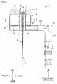
- FIG. 1 is a cross section of a melt spinning device of the present embodiment.
- FIG. 2 is a cross section taken along a line II-II in FIG. 1 .
- the description below is given on the premise that the up-down direction, front-back direction, and left-right direction in FIG. 1 and FIG. 2 are respectively the up-down direction, front-back direction, and left-right direction relative to a melt spinning device 1 in the present embodiment.
- the melt spinning device 1 of the present embodiment includes members such as a spinning device 2, a yarn cooler 3, and oil guides 4.
- the spinning device 2 includes a spinning beam 10 and pack housings 11 provided in the spinning beam 10.
- spinning packs 12 are attached, respectively.
- the pack housings 11 are staggered to form two lines along the left-right direction (i.e., the direction orthogonal to the sheet of FIG. 1 ).
- molten polymer is supplied from an unillustrated pipe or the like in the spinning beam 10.
- Each spinning pack 12 has, at its lower end portion, a spinneret 13 having nozzles.
- the supplied molten polymer is spun out from the spinning pack 12 through the nozzles of the spinneret 13.
- the polymer spun out through the nozzles is cooled at the yarn cooler 3 into filaments f.
- the yarn cooler 3 will be described later.
- one multi-filament yarn Y formed of plural filaments f is spun out from one spinneret 13.
- the yarn cooler 3 is provided below the spinning device 2.
- the yarn cooler 3 is configured to cool and solidify molten polymer spun out from the spinning packs 12.
- the yarn cooler 3 includes: a box 20; cooling cylinders 21 (yarn cooling unit(s) of the present invention) accommodated in the box 20; and partitioning cylinders 22.
- the internal space of the box 20 is partitioned into upper and lower spaces by a horizontal flow adjustment plate 23 made of a material having flow adjustment capability such as punching metal.
- the cooling cylinders 21 are provided directly below the spinning packs 12, respectively. That is, the cooling cylinders 21 are staggered along the left-right direction in accordance with the arrangement of the spinning packs 12, as shown in FIG. 2 .
- the wall of each cooling cylinder 21 is, in a manner similar to the flow adjustment plate 23, made of a material having flow adjustment capability such as punching metal.
- the partitioning cylinders 22 are provided directly below the cooling cylinders 21, respectively. Being different from the cooling cylinders 21, the wall of each partitioning cylinder 22 is made of an air-impermeable material.
- a yarn Y spun out from a spinning pack 12 and made of filaments f passes through the internal spaces of the cooling cylinder 21 and the partitioning cylinder 22 which are directly below the spinning pack 12.
- a duct 25 is coupled, at its one end, to a lower portion of a rear side wall of the box 20.
- the other end of the duct 25 is coupled to a compressed air source via an unillustrated main duct to which multiple ducts are connected.
- the compressed air source includes a compressor, a humidity controller, a compressed air tank, and the like, though not illustrated.
- the compressed air source feeds air as gas for cooling. Air from the compressed air source is supplied to the lower space of the box 20 through the duct 25. The details of the structure of the duct 25 will be described later.
- the flow of cooling air having entered the lower space of the box 20 is adjusted upward while passing through the horizontal flow adjustment plate 23, and flows into the upper space of the box 20. Because the wall of each partitioning cylinder 22 is air-impermeable, the cooling air does not directly flows from the lower space of the box 20 into the partitioning cylinder 22.
- the flow of air having entered the upper space of the box 20 is adjusted when passing through the wall of each cooling cylinder 21, and flows into each cooling cylinder 21.
- the air is blown to each yarn Y made of the filaments f from the entire outer circumference of the corresponding cooling cylinder 21, so that each yarn Y is cooled in the corresponding cooling cylinder 21.
- Each oil guide 4 is provided below the corresponding cooling cylinder 21 and partitioning cylinder 22.
- the yarn Y having been cooled in the cooling cylinder 21 comes into contact with the oil guide 4.
- the oil guide 4 discharges oil to the yarn Y so that the oil is applied to the yarn Y.
- the yarn Y to which the oil has been applied by the oil guide 4 is taken up by a take-up roller (not illustrated) provided below the oil guide 4.
- the yarn Y is then sent to a winding device (not illustrated) and is wound onto a bobbin (not illustrated) at the winding device.
- the duct 25 includes: a vertical passage portion 26 extending in the up-down direction; and a horizontal passage portion 27 extending in the front-back direction.
- the lower end of the vertical passage portion 26 is coupled to the aforementioned compressed air source via the main duct which is not illustrated.
- the horizontal passage portion 27 extends horizontally from the upper end of the vertical passage portion 26, and is coupled to the lower portion of the rear side wall of the box 20. Air fed from the compressed air source flows to the box 20, through the vertical passage portion 26 and the horizontal passage portion 27 of the duct 25.
- FIG. 3A is a cross section taken along a line III-III in FIG. 1 .
- FIG. 3B is an enlarged view of a bulging portion of each flow adjustment plate 29 shown in FIG. 3A .
- an upper end portion of the vertical passage portion 26 of the duct 25 forms a passage-enlarged portion 28.
- the passage-enlarged portion 28 has a sectorial shape such that the width of a passage therein (i.e., the width in the left-right direction) increases upward (i.e., toward the cooling cylinders 21).
- the width of the passage in the duct 25 is referred to as a "passage width".
- Two side walls 30 of the passage-enlarged portion 28 extend to be inclined with respect to the up-down direction so that the distances from a central axis C to the side walls 30 increase in a left-right symmetrical manner.
- the horizontal passage portion 27 is coupled to an upper end portion (exit portion 28b) of the passage-enlarged portion 28.
- the passage width of the duct 25 increases at the passage-enlarged portion 28, which is a midway portion of the duct 25.
- the horizontal passage portion 27 connected to the passage-enlarged portion 28 extends to the box 20 while keeping the increased passage width.
- the cooling cylinders 21 arranged in the left-right direction are accommodated in the box 20, and the duct 25 is coupled to the rear wall of the box 20, which is a side portion of the box 20 located on a side of the box 20 in a direction orthogonal to the arrangement direction of the cooling cylinders 21. Due to the above structure, if air flowing in the duct 25 with unevenness in its flow rate in the width direction (left-right direction) enters the box 20, there is caused a variation in the speeds at which air enters into the cooling cylinders 21 in the box 20. This causes a difference in the yarn-cooling capability. To minimize such a variation in the speeds at the exit portion 28b of the passage-enlarged portion 28, thereby to minimize the difference in the cooling capability among the cooling cylinders 21, the present embodiment employs the following arrangement.
- flow adjustment plates 29 are provided in the passage-enlarged portion 28.
- the flow adjustment plates 29 adjust the flow of air so that air having entered through the entrance portion 28a spreads uniformly with respect to the width direction.
- the flow adjustment plates 29 are arranged so as to radially fan out from the entrance portion 28a with the smaller passage width toward the exit portion 28b with the larger passage width.
- the flow adjustment plates 29 are arranged at equal intervals of an angle ⁇ (theta). If the gap between each two adjacent flow adjustment plates 29 is too narrow, it is difficult for air to flow. Meanwhile, if the gap is too wide, their flow adjustment effect is low.
- the angle ⁇ (theta) between each two adjacent flow adjustment plates 29 is preferably not less than 6 degrees and not more than 16 degrees, and more preferably 8 degrees.
- each flow adjustment plate 29 has a bulging portion 32 at an entrance-side end portion of the plate 29, which end portion is closer to the entrance portion 28a (i.e., an end portion upstream in the flow path).
- the thickness of the bulging portion 32 is larger than the thickness of a portion of the flow adjustment plate 29 that is located above the bulging portion 32 (portion on a side closer to the cooling cylinders 21 than the bulging portion 32).
- the bulging portion 32 has a curved surface.
- a cylindrical rod 31 extending in the direction orthogonal to the sheet of FIG. 3 is attached to an entrance-side end portion of a plate member of each flow adjustment plate 29. With this, the bulging portion 32 having a circular cross section is provided.
- each flow adjustment plate 29 does not have the bulging portion 32.
- the air collides with the entrance-side end portions of the flow adjustment plates 29.
- the flow of air is more likely to greatly deviate from the flow adjustment plates 29 to cause a disturbance of the flow.
- each flow adjustment plate 29 has the bulging portion 32 at the entrance-side end portion of the plate. This arrangement enables air having entered the passage-enlarged portion 28 to flow along the surfaces of the bulging portions 32 into the gaps between the flow adjustment plates 29. Thus, it is less likely that the flow of air greatly deviates from the flow adjustment plates 29, to reduce the possibility of the disturbance of the flow.
- each bulging portion 32 makes it easier for air to flow along the surface of the bulging portion 32, and reduces the possibility that the flow of air deviates from the flow adjustment plates 29. Further, the bulging portions 32 each having the circular cross sectional shape are processed easily, and advantageous in terms of cost. Specifically, each bulging portion 32 is produced merely by attaching the cylindrical rod 31 to the plate member constituting the flow adjustment plate 29.
- each bulging portion 32 is too small, the effect of reducing the possibility of the deviation from the flow adjustment plates 29 is small. To the contrary, if each bulging portion 32 is too large, there is a large passage resistance, which makes it difficult for air to enter the gaps between the flow adjustment plates 29.
- the diameter of each cylindrical rod 31 constituting the bulging portion 32 is preferably not less than 5 mm and not more than 16 mm, and more preferably 8 mm.
- the thickness of each flow adjustment plate 29 is on the order of 0.5 mm, for example.
- FIG. 4 is an enlarged view of a different shape of bulging portion 32A of each flow adjustment plate 29.
- the bulging portion 32A has a triangular cross sectional shape widening toward the exit portion 28b of the passage-enlarged portion 28, as shown in FIG. 4 .
- the bulging portion may have such a shape instead of the circular cross sectional shape shown in FIG. 3B .
- the triangular cross sectional shape of the bulging portion 32A prevents air having collided with the end portion of each flow adjustment plate 29 from greatly deviating from the flow adjustment plate 29, and makes it easier for air to flow along the flow adjustment plate 29.
- the bulging portions 32 of the flow adjustment plates 29 are linearly arranged in the width direction of the passage-enlarged portion 28, air having entered the passage-enlarged portion 28 collides with a row of the bulging portions 32 arranged at narrow intervals. For this reason, a disturbance of airflow is more likely to occur.
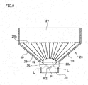
- the bulging portions 32 of the flow adjustment plates 29 are arranged along a virtual circular arc 35 protruding toward the exit portion 28b of the passage-enlarged portion 28 (toward the cooling cylinders 21), as shown in FIG. 3 .
- a space 36 partially surrounded by the bulging portions 32 arranged in a circular arc is created at the entrance portion 28a of the passage-enlarged portion 28.
- air having entered the passage-enlarged portion 28 first flowing through the above space 36, and then, smoothly enters the gaps between the flow adjustment plates 29 while spreading radially. Because of this, the disturbance of airflow is less likely to occur.
- an intersection point P1 of extension lines L of the two side walls 30 of the passage-enlarged portion 28 matches a center point P2 of the circular arc 35 along which the bulging portions 32 are arranged.
- radially fanning out streamlines of air flowing while spreading in the passage-enlarged portion 28 are orthogonal to the circular arc 35 along which the bulging portions 32 are arranged. This makes it easier for air to enter the gaps between the bulging portions 32.
- the curvature of the circular arc 35 may vary depending on the shape of the passage-enlarged portion 28. For example, the curvature radius R of the circular arc 35 is 135 mm plus or minus 5.
- Exit-side end portions of the flow adjustment plates 29 are level with the end of the exit portion 28b of the passage-enlarged portion 28, and arranged on a straight line. This ensures that the flow of air having entered the passage-enlarged portion 28 is adjusted by the flow adjustment plates 29 before reaching the exit portion 28b of the passage-enlarged portion 28.
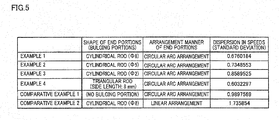
- FIG. 6A to FIG. 7C respectively show the analysis results (speed distributions) for Examples 1 to 4 and Comparative Examples 1 and 2.
- the column "dispersion in speeds" in FIG. 5 has values showing the degree of dispersion in the speeds with respect to the width direction at the exit portion 28b of the passage-enlarged portion 28, expressed as standard deviation.
- the values representing the degree of dispersion in the speeds (standard deviation) in FIG. 5 the value closest to 0 (zero) has the lowest degree of the dispersion.
- each flow adjustment plate 29 has no bulging portion 32.
- the bulging portions 32 are provided but arranged linearly.
- each bulging portion 32 is formed by a cylindrical rod having a diameter of 8 mm.
- each bulging portion 32 is formed by a triangular rod with a side length of 8 mm.
- the yarn cooler of the above-described embodiment includes the cooling cylinders 21, as the yarn cooling unit(s), each configured so that air is blown to the yarn from the entire outer circumference.
- the configuration of the yarn cooling unit is not limited to this.
- the yarn cooling unit(s) may be configured to cool the yarn by air blown to the yarn only in a single direction, i.e., may have a so-called crossflow design.
Landscapes
- Engineering & Computer Science (AREA)
- Mechanical Engineering (AREA)
- Textile Engineering (AREA)
- Spinning Methods And Devices For Manufacturing Artificial Fibers (AREA)
Claims (8)
- Garnkühler (3) umfassend:mindestens eine Garnkühleinheit (21), konfiguriert zum Kühlen eines Garns (Y), das aus einer Spinnvorrichtung (2) ausgesponnen wird, durch auf das Garn (Y) geblasenes Gas; undeine Gaszuführungseinheit (25), die einen Durchgang (26) aufweist, durch den Gas der Garnkühleinheit (21) zugeführt wird,wobei die Gaszuführungseinheit (25) beinhaltet:einen sektorähnlichen durchgangsvergrößerten Abschnitt (28), in dem die Breite des Durchgangs (26) zur Garnkühleinheit (21) zunimmt; undeine Vielzahl von Strömungseinstellplatten (29), so in dem durchgangsvergrößerten Abschnitt (28) angeordnet, dass sie radial zu einem Ausgangsabschnitt (28b) des durchgangsvergrößerten Abschnitts (28) auffächern, wobei jede der Strömungseinstellplatten (29) einen Wulstabschnitt (32) an ihrem Endabschnitt beinhaltet, der näher zu einem Eintrittsabschnitt (28a) des durchgangsvergrößerten Abschnitts (28) ist,wobei die Wulstabschnitte (32) in einem Bogen (35) vorspringend zu dem Ausgangsabschnitt (28b) des durchgangsvergrößerten Abschnitts (28) angeordnet sind.
- Garnkühler (3) nach Anspruch 1, wobei jeder Wulstabschnitt (32) eine gekrümmte Oberfläche aufweist.
- Garnkühler (3) nach Anspruch 2, wobei jeder Wulstabschnitt (32) eine kreisförmige Querschnittsform aufweist.
- Garnkühler (3) nach Anspruch 3, wobei ein Durchmesser von jedem Wulstabschnitt (32) nicht weniger als 5 mm und nicht mehr als 16 mm beträgt.
- Garnkühler (3) nach Anspruch 1, wobei jeder Wulstabschnitt (32) eine dreieckige Querschnittsform aufweist, die sich zu dem Ausgangsabschnitt (28b) des durchgangsvergrößerten Abschnitts (28) weitet.
- Garnkühler (3) nach einem der Ansprüche 1 bis 5, wobei ein Schnittpunkt (P1) der Verlängerungslinien (L) von zwei Seitenwänden (30) des sektorähnlichen durchgangsvergrößerten Abschnitts (28) mit einem Mittelpunkt (P2) des Bogens (35), entlang dem die Wulstabschnitte (32) angeordnet sind, übereinstimmt.
- Garnkühler (3) nach einem der Ansprüche 1 bis 6, wobei ein Winkel (θ) zwischen jeder der zwei benachbarten Platten der Strömungseinstellplatten (29) nicht weniger als 6 Grad und nicht mehr als 16 Grad beträgt.
- Garnkühler (3) nach einem der Ansprüche 1 bis 7, wobei die mindestens eine Garnkühleinheit (21) eine Vielzahl von Garnkühleinheiten (21) enthält, wobei der Garnkühler (3) weiter einen Kasten (20) enthält, in dem die Garnkühleinheiten (21) untergebracht sind,
die Garnkühleinheiten (21) in einer vorbestimmten Richtung in dem Kasten (20) angeordnet sind und der Ausgangsabschnitt (28b) des durchgangsvergrößerten Abschnitts (28) mit einem Seitenabschnitt des Kastens (20) gekoppelt ist, der sich auf einer Seite des Kastens (20) in einer Richtung rechtwinklig zu der vorbestimmten Richtung befindet.
Applications Claiming Priority (1)
| Application Number | Priority Date | Filing Date | Title |
|---|---|---|---|
| JP2016027676A JP6556641B2 (ja) | 2016-02-17 | 2016-02-17 | 糸冷却装置 |
Publications (2)
| Publication Number | Publication Date |
|---|---|
| EP3208367A1 EP3208367A1 (de) | 2017-08-23 |
| EP3208367B1 true EP3208367B1 (de) | 2018-03-14 |
Family
ID=57984807
Family Applications (1)
| Application Number | Title | Priority Date | Filing Date |
|---|---|---|---|
| EP17154570.0A Active EP3208367B1 (de) | 2016-02-17 | 2017-02-03 | Garnkühler |
Country Status (3)
| Country | Link |
|---|---|
| EP (1) | EP3208367B1 (de) |
| JP (1) | JP6556641B2 (de) |
| CN (1) | CN107090602B (de) |
Families Citing this family (4)
| Publication number | Priority date | Publication date | Assignee | Title |
|---|---|---|---|---|
| CN108088279A (zh) * | 2017-12-12 | 2018-05-29 | 无锡市金来生物科技有限公司 | 物料冷却塔 |
| JP7149100B2 (ja) | 2018-05-16 | 2022-10-06 | Tmtマシナリー株式会社 | 紡糸冷却装置 |
| CN111041660B (zh) * | 2019-12-19 | 2022-02-11 | 杭州华利实业集团有限公司 | 吸湿速干列车卧具及其制造方法 |
| CN115182059B (zh) * | 2022-06-13 | 2023-11-14 | 桐昆集团浙江恒超化纤有限公司 | 高弹春亚纺专用聚酯纤维纺丝设备及纺丝工艺 |
Family Cites Families (19)
| Publication number | Priority date | Publication date | Assignee | Title |
|---|---|---|---|---|
| JPS4734257Y1 (de) * | 1969-07-31 | 1972-10-17 | ||
| JPS51144511U (de) * | 1975-05-06 | 1976-11-20 | ||
| DD123955A1 (de) * | 1976-02-13 | 1977-01-26 | ||
| DE2923700A1 (de) * | 1979-06-12 | 1980-12-18 | Werner Singendonk | Spinnmaschine mit blasschacht |
| JPH0311065U (de) * | 1989-06-19 | 1991-02-01 | ||
| JPH08201215A (ja) | 1995-01-23 | 1996-08-09 | Mitsubishi Heavy Ind Ltd | 整流ダクト |
| JPH10158920A (ja) * | 1996-11-19 | 1998-06-16 | Toray Eng Co Ltd | 糸条冷却装置 |
| JP3060102U (ja) * | 1998-11-09 | 1999-07-30 | 清坤 曽 | 紡糸冷却機構 |
| JP2003213517A (ja) * | 2002-01-18 | 2003-07-30 | Toray Ind Inc | 合成繊維の製造方法および装置 |
| JP3781735B2 (ja) * | 2003-04-07 | 2006-05-31 | シャープ株式会社 | 整流装置 |
| JP4829002B2 (ja) | 2006-04-28 | 2011-11-30 | 川崎重工業株式会社 | 横風送風装置 |
| CN101535537B (zh) * | 2006-11-10 | 2011-01-26 | 欧瑞康纺织有限及两合公司 | 用于熔融纺制和冷却合成单丝的方法及装置 |
| JP4772759B2 (ja) * | 2007-07-26 | 2011-09-14 | 株式会社東芝 | ディフューザ |
| JP2010077553A (ja) * | 2008-09-25 | 2010-04-08 | Toray Ind Inc | フィラメント糸の製造装置および方法 |
| JP5596422B2 (ja) * | 2010-06-04 | 2014-09-24 | Tmtマシナリー株式会社 | 糸条冷却装置 |
| JP5925657B2 (ja) * | 2012-10-03 | 2016-05-25 | Tmtマシナリー株式会社 | 溶融紡糸装置 |
| JP6069019B2 (ja) * | 2013-02-19 | 2017-01-25 | Tmtマシナリー株式会社 | 糸条冷却装置 |
| JP2015014071A (ja) * | 2013-07-08 | 2015-01-22 | Tmtマシナリー株式会社 | 糸条冷却装置 |
| CN105177738B (zh) * | 2015-09-30 | 2017-09-22 | 苏州金泉新材料股份有限公司 | 熔融纺丝用的环吹风冷却装置 |
-
2016
- 2016-02-17 JP JP2016027676A patent/JP6556641B2/ja active Active
-
2017
- 2017-02-03 EP EP17154570.0A patent/EP3208367B1/de active Active
- 2017-02-07 CN CN201710067513.8A patent/CN107090602B/zh active Active
Non-Patent Citations (1)
| Title |
|---|
| None * |
Also Published As
| Publication number | Publication date |
|---|---|
| EP3208367A1 (de) | 2017-08-23 |
| JP6556641B2 (ja) | 2019-08-07 |
| CN107090602A (zh) | 2017-08-25 |
| CN107090602B (zh) | 2020-07-14 |
| JP2017145525A (ja) | 2017-08-24 |
Similar Documents
| Publication | Publication Date | Title |
|---|---|---|
| EP3208367B1 (de) | Garnkühler | |
| CN110541241B (zh) | 用于由连续长丝制造纺粘型非织造织物的设备和方法 | |
| EP3492634B1 (de) | Schmelzspinnvorrichtung | |
| JP5526531B2 (ja) | 紡糸用冷却装置および溶融紡糸方法 | |
| JP6069019B2 (ja) | 糸条冷却装置 | |
| JP2015014071A (ja) | 糸条冷却装置 | |
| US6705852B2 (en) | Melt spinning apparatus | |
| EP1629141B1 (de) | Vorrichtung und verfahren zur steuerung der luftströme in einer anlage zur faserherstellung durch extrusion | |
| JP2010070887A (ja) | 紡糸用冷却装置および溶融紡糸方法 | |
| CN106637443B (zh) | 侧吹风装置和纺丝机 | |
| EP3441507B1 (de) | Garnkühler | |
| US20160160395A1 (en) | Gas supply blowout nozzle and method of producing flame-proofed fiber and carbon fiber | |
| JP2006241611A (ja) | 合成繊維の溶融紡糸装置 | |
| JP4988318B2 (ja) | 多錘の溶融紡糸装置およびそれから得られる極細マルチフィラメント糸条 | |
| JP2002038328A (ja) | 溶融紡糸装置 | |
| EP4729671A1 (de) | Garnkühlvorrichtung | |
| CN103710768A (zh) | 熔融纺丝装置 | |
| JP7656522B2 (ja) | 紡糸生産設備 | |
| EP4596767A1 (de) | Verwirbelungsvorrichtung und aufnahmemaschine für gesponnenes garn | |
| JP5332253B2 (ja) | フィラメント糸の製造装置および製造方法 | |
| JP3176781B2 (ja) | 紡糸筒 | |
| JPH07109614A (ja) | 極細マルチフィラメント糸の溶融紡糸方法及びその装置 | |
| EP3670712A1 (de) | Ausstossdüse für eine nanofaserherstellungsvorrichtung und nanofaserherstellungsvorrichtung mit einer ausstossdüse | |
| FI127025B (sv) | Förfarande vid framställning av mineralull | |
| BR102019010160B1 (pt) | Aparelho para produção de não tecidos fabricados por fiação contínua a partir de filamentos contínuos |
Legal Events
| Date | Code | Title | Description |
|---|---|---|---|
| PUAI | Public reference made under article 153(3) epc to a published international application that has entered the european phase |
Free format text: ORIGINAL CODE: 0009012 |
|
| STAA | Information on the status of an ep patent application or granted ep patent |
Free format text: STATUS: THE APPLICATION HAS BEEN PUBLISHED |
|
| AK | Designated contracting states |
Kind code of ref document: A1 Designated state(s): AL AT BE BG CH CY CZ DE DK EE ES FI FR GB GR HR HU IE IS IT LI LT LU LV MC MK MT NL NO PL PT RO RS SE SI SK SM TR |
|
| AX | Request for extension of the european patent |
Extension state: BA ME |
|
| STAA | Information on the status of an ep patent application or granted ep patent |
Free format text: STATUS: REQUEST FOR EXAMINATION WAS MADE |
|
| 17P | Request for examination filed |
Effective date: 20171017 |
|
| RBV | Designated contracting states (corrected) |
Designated state(s): AL AT BE BG CH CY CZ DE DK EE ES FI FR GB GR HR HU IE IS IT LI LT LU LV MC MK MT NL NO PL PT RO RS SE SI SK SM TR |
|
| GRAP | Despatch of communication of intention to grant a patent |
Free format text: ORIGINAL CODE: EPIDOSNIGR1 |
|
| STAA | Information on the status of an ep patent application or granted ep patent |
Free format text: STATUS: GRANT OF PATENT IS INTENDED |
|
| INTG | Intention to grant announced |
Effective date: 20171201 |
|
| GRAS | Grant fee paid |
Free format text: ORIGINAL CODE: EPIDOSNIGR3 |
|
| GRAA | (expected) grant |
Free format text: ORIGINAL CODE: 0009210 |
|
| STAA | Information on the status of an ep patent application or granted ep patent |
Free format text: STATUS: THE PATENT HAS BEEN GRANTED |
|
| AK | Designated contracting states |
Kind code of ref document: B1 Designated state(s): AL AT BE BG CH CY CZ DE DK EE ES FI FR GB GR HR HU IE IS IT LI LT LU LV MC MK MT NL NO PL PT RO RS SE SI SK SM TR |
|
| REG | Reference to a national code |
Ref country code: GB Ref legal event code: FG4D |
|
| REG | Reference to a national code |
Ref country code: CH Ref legal event code: EP Ref country code: AT Ref legal event code: REF Ref document number: 978975 Country of ref document: AT Kind code of ref document: T Effective date: 20180315 |
|
| REG | Reference to a national code |
Ref country code: IE Ref legal event code: FG4D |
|
| REG | Reference to a national code |
Ref country code: DE Ref legal event code: R096 Ref document number: 602017000014 Country of ref document: DE |
|
| REG | Reference to a national code |
Ref country code: NL Ref legal event code: MP Effective date: 20180314 |
|
| REG | Reference to a national code |
Ref country code: LT Ref legal event code: MG4D |
|
| PG25 | Lapsed in a contracting state [announced via postgrant information from national office to epo] |
Ref country code: LT Free format text: LAPSE BECAUSE OF FAILURE TO SUBMIT A TRANSLATION OF THE DESCRIPTION OR TO PAY THE FEE WITHIN THE PRESCRIBED TIME-LIMIT Effective date: 20180314 Ref country code: HR Free format text: LAPSE BECAUSE OF FAILURE TO SUBMIT A TRANSLATION OF THE DESCRIPTION OR TO PAY THE FEE WITHIN THE PRESCRIBED TIME-LIMIT Effective date: 20180314 Ref country code: CY Free format text: LAPSE BECAUSE OF FAILURE TO SUBMIT A TRANSLATION OF THE DESCRIPTION OR TO PAY THE FEE WITHIN THE PRESCRIBED TIME-LIMIT Effective date: 20180314 Ref country code: NO Free format text: LAPSE BECAUSE OF FAILURE TO SUBMIT A TRANSLATION OF THE DESCRIPTION OR TO PAY THE FEE WITHIN THE PRESCRIBED TIME-LIMIT Effective date: 20180614 Ref country code: FI Free format text: LAPSE BECAUSE OF FAILURE TO SUBMIT A TRANSLATION OF THE DESCRIPTION OR TO PAY THE FEE WITHIN THE PRESCRIBED TIME-LIMIT Effective date: 20180314 |
|
| REG | Reference to a national code |
Ref country code: AT Ref legal event code: MK05 Ref document number: 978975 Country of ref document: AT Kind code of ref document: T Effective date: 20180314 |
|
| PG25 | Lapsed in a contracting state [announced via postgrant information from national office to epo] |
Ref country code: RS Free format text: LAPSE BECAUSE OF FAILURE TO SUBMIT A TRANSLATION OF THE DESCRIPTION OR TO PAY THE FEE WITHIN THE PRESCRIBED TIME-LIMIT Effective date: 20180314 Ref country code: BG Free format text: LAPSE BECAUSE OF FAILURE TO SUBMIT A TRANSLATION OF THE DESCRIPTION OR TO PAY THE FEE WITHIN THE PRESCRIBED TIME-LIMIT Effective date: 20180614 Ref country code: GR Free format text: LAPSE BECAUSE OF FAILURE TO SUBMIT A TRANSLATION OF THE DESCRIPTION OR TO PAY THE FEE WITHIN THE PRESCRIBED TIME-LIMIT Effective date: 20180615 Ref country code: LV Free format text: LAPSE BECAUSE OF FAILURE TO SUBMIT A TRANSLATION OF THE DESCRIPTION OR TO PAY THE FEE WITHIN THE PRESCRIBED TIME-LIMIT Effective date: 20180314 Ref country code: SE Free format text: LAPSE BECAUSE OF FAILURE TO SUBMIT A TRANSLATION OF THE DESCRIPTION OR TO PAY THE FEE WITHIN THE PRESCRIBED TIME-LIMIT Effective date: 20180314 |
|
| PG25 | Lapsed in a contracting state [announced via postgrant information from national office to epo] |
Ref country code: AL Free format text: LAPSE BECAUSE OF FAILURE TO SUBMIT A TRANSLATION OF THE DESCRIPTION OR TO PAY THE FEE WITHIN THE PRESCRIBED TIME-LIMIT Effective date: 20180314 Ref country code: RO Free format text: LAPSE BECAUSE OF FAILURE TO SUBMIT A TRANSLATION OF THE DESCRIPTION OR TO PAY THE FEE WITHIN THE PRESCRIBED TIME-LIMIT Effective date: 20180314 Ref country code: NL Free format text: LAPSE BECAUSE OF FAILURE TO SUBMIT A TRANSLATION OF THE DESCRIPTION OR TO PAY THE FEE WITHIN THE PRESCRIBED TIME-LIMIT Effective date: 20180314 Ref country code: EE Free format text: LAPSE BECAUSE OF FAILURE TO SUBMIT A TRANSLATION OF THE DESCRIPTION OR TO PAY THE FEE WITHIN THE PRESCRIBED TIME-LIMIT Effective date: 20180314 Ref country code: PL Free format text: LAPSE BECAUSE OF FAILURE TO SUBMIT A TRANSLATION OF THE DESCRIPTION OR TO PAY THE FEE WITHIN THE PRESCRIBED TIME-LIMIT Effective date: 20180314 |
|
| PG25 | Lapsed in a contracting state [announced via postgrant information from national office to epo] |
Ref country code: SK Free format text: LAPSE BECAUSE OF FAILURE TO SUBMIT A TRANSLATION OF THE DESCRIPTION OR TO PAY THE FEE WITHIN THE PRESCRIBED TIME-LIMIT Effective date: 20180314 Ref country code: CZ Free format text: LAPSE BECAUSE OF FAILURE TO SUBMIT A TRANSLATION OF THE DESCRIPTION OR TO PAY THE FEE WITHIN THE PRESCRIBED TIME-LIMIT Effective date: 20180314 Ref country code: AT Free format text: LAPSE BECAUSE OF FAILURE TO SUBMIT A TRANSLATION OF THE DESCRIPTION OR TO PAY THE FEE WITHIN THE PRESCRIBED TIME-LIMIT Effective date: 20180314 Ref country code: SM Free format text: LAPSE BECAUSE OF FAILURE TO SUBMIT A TRANSLATION OF THE DESCRIPTION OR TO PAY THE FEE WITHIN THE PRESCRIBED TIME-LIMIT Effective date: 20180314 |
|
| REG | Reference to a national code |
Ref country code: DE Ref legal event code: R097 Ref document number: 602017000014 Country of ref document: DE |
|
| PG25 | Lapsed in a contracting state [announced via postgrant information from national office to epo] |
Ref country code: PT Free format text: LAPSE BECAUSE OF FAILURE TO SUBMIT A TRANSLATION OF THE DESCRIPTION OR TO PAY THE FEE WITHIN THE PRESCRIBED TIME-LIMIT Effective date: 20180716 |
|
| PLBE | No opposition filed within time limit |
Free format text: ORIGINAL CODE: 0009261 |
|
| STAA | Information on the status of an ep patent application or granted ep patent |
Free format text: STATUS: NO OPPOSITION FILED WITHIN TIME LIMIT |
|
| PG25 | Lapsed in a contracting state [announced via postgrant information from national office to epo] |
Ref country code: DK Free format text: LAPSE BECAUSE OF FAILURE TO SUBMIT A TRANSLATION OF THE DESCRIPTION OR TO PAY THE FEE WITHIN THE PRESCRIBED TIME-LIMIT Effective date: 20180314 |
|
| 26N | No opposition filed |
Effective date: 20181217 |
|
| PG25 | Lapsed in a contracting state [announced via postgrant information from national office to epo] |
Ref country code: IT Free format text: LAPSE BECAUSE OF FAILURE TO SUBMIT A TRANSLATION OF THE DESCRIPTION OR TO PAY THE FEE WITHIN THE PRESCRIBED TIME-LIMIT Effective date: 20180314 |
|
| PG25 | Lapsed in a contracting state [announced via postgrant information from national office to epo] |
Ref country code: ES Free format text: LAPSE BECAUSE OF FAILURE TO SUBMIT A TRANSLATION OF THE DESCRIPTION OR TO PAY THE FEE WITHIN THE PRESCRIBED TIME-LIMIT Effective date: 20180314 |
|
| PG25 | Lapsed in a contracting state [announced via postgrant information from national office to epo] |
Ref country code: LU Free format text: LAPSE BECAUSE OF NON-PAYMENT OF DUE FEES Effective date: 20190203 Ref country code: MC Free format text: LAPSE BECAUSE OF FAILURE TO SUBMIT A TRANSLATION OF THE DESCRIPTION OR TO PAY THE FEE WITHIN THE PRESCRIBED TIME-LIMIT Effective date: 20180314 |
|
| REG | Reference to a national code |
Ref country code: BE Ref legal event code: MM Effective date: 20190228 |
|
| REG | Reference to a national code |
Ref country code: IE Ref legal event code: MM4A |
|
| PG25 | Lapsed in a contracting state [announced via postgrant information from national office to epo] |
Ref country code: IE Free format text: LAPSE BECAUSE OF NON-PAYMENT OF DUE FEES Effective date: 20190203 |
|
| PG25 | Lapsed in a contracting state [announced via postgrant information from national office to epo] |
Ref country code: FR Free format text: LAPSE BECAUSE OF NON-PAYMENT OF DUE FEES Effective date: 20190228 Ref country code: BE Free format text: LAPSE BECAUSE OF NON-PAYMENT OF DUE FEES Effective date: 20190228 |
|
| PG25 | Lapsed in a contracting state [announced via postgrant information from national office to epo] |
Ref country code: TR Free format text: LAPSE BECAUSE OF FAILURE TO SUBMIT A TRANSLATION OF THE DESCRIPTION OR TO PAY THE FEE WITHIN THE PRESCRIBED TIME-LIMIT Effective date: 20180314 |
|
| PG25 | Lapsed in a contracting state [announced via postgrant information from national office to epo] |
Ref country code: MT Free format text: LAPSE BECAUSE OF NON-PAYMENT OF DUE FEES Effective date: 20190203 |
|
| REG | Reference to a national code |
Ref country code: CH Ref legal event code: PL |
|
| PG25 | Lapsed in a contracting state [announced via postgrant information from national office to epo] |
Ref country code: LI Free format text: LAPSE BECAUSE OF NON-PAYMENT OF DUE FEES Effective date: 20200229 Ref country code: CH Free format text: LAPSE BECAUSE OF NON-PAYMENT OF DUE FEES Effective date: 20200229 |
|
| PG25 | Lapsed in a contracting state [announced via postgrant information from national office to epo] |
Ref country code: IS Free format text: LAPSE BECAUSE OF FAILURE TO SUBMIT A TRANSLATION OF THE DESCRIPTION OR TO PAY THE FEE WITHIN THE PRESCRIBED TIME-LIMIT Effective date: 20180714 |
|
| PG25 | Lapsed in a contracting state [announced via postgrant information from national office to epo] |
Ref country code: HU Free format text: LAPSE BECAUSE OF FAILURE TO SUBMIT A TRANSLATION OF THE DESCRIPTION OR TO PAY THE FEE WITHIN THE PRESCRIBED TIME-LIMIT; INVALID AB INITIO Effective date: 20170203 |
|
| GBPC | Gb: european patent ceased through non-payment of renewal fee |
Effective date: 20210203 |
|
| PG25 | Lapsed in a contracting state [announced via postgrant information from national office to epo] |
Ref country code: SI Free format text: LAPSE BECAUSE OF FAILURE TO SUBMIT A TRANSLATION OF THE DESCRIPTION OR TO PAY THE FEE WITHIN THE PRESCRIBED TIME-LIMIT Effective date: 20180314 |
|
| PG25 | Lapsed in a contracting state [announced via postgrant information from national office to epo] |
Ref country code: GB Free format text: LAPSE BECAUSE OF NON-PAYMENT OF DUE FEES Effective date: 20210203 |
|
| PG25 | Lapsed in a contracting state [announced via postgrant information from national office to epo] |
Ref country code: MK Free format text: LAPSE BECAUSE OF FAILURE TO SUBMIT A TRANSLATION OF THE DESCRIPTION OR TO PAY THE FEE WITHIN THE PRESCRIBED TIME-LIMIT Effective date: 20180314 |
|
| P01 | Opt-out of the competence of the unified patent court (upc) registered |
Effective date: 20230426 |
|
| PGFP | Annual fee paid to national office [announced via postgrant information from national office to epo] |
Ref country code: DE Payment date: 20260225 Year of fee payment: 10 |