EP3208068B1 - Vorrichtung zur induktionserwärmung und biegung von thermoplastischen verbundrohren und verfahren zur verwendung davon - Google Patents
Vorrichtung zur induktionserwärmung und biegung von thermoplastischen verbundrohren und verfahren zur verwendung davon Download PDFInfo
- Publication number
- EP3208068B1 EP3208068B1 EP17155840.6A EP17155840A EP3208068B1 EP 3208068 B1 EP3208068 B1 EP 3208068B1 EP 17155840 A EP17155840 A EP 17155840A EP 3208068 B1 EP3208068 B1 EP 3208068B1
- Authority
- EP
- European Patent Office
- Prior art keywords
- composite tube
- turn
- bending
- induction coil
- zone
- Prior art date
- Legal status (The legal status is an assumption and is not a legal conclusion. Google has not performed a legal analysis and makes no representation as to the accuracy of the status listed.)
- Active
Links
Images



Classifications
-
- B—PERFORMING OPERATIONS; TRANSPORTING
- B29—WORKING OF PLASTICS; WORKING OF SUBSTANCES IN A PLASTIC STATE IN GENERAL
- B29C—SHAPING OR JOINING OF PLASTICS; SHAPING OF MATERIAL IN A PLASTIC STATE, NOT OTHERWISE PROVIDED FOR; AFTER-TREATMENT OF THE SHAPED PRODUCTS, e.g. REPAIRING
- B29C53/00—Shaping by bending, folding, twisting, straightening or flattening; Apparatus therefor
- B29C53/02—Bending or folding
- B29C53/08—Bending or folding of tubes or other profiled members
- B29C53/083—Bending or folding of tubes or other profiled members bending longitudinally, i.e. modifying the curvature of the tube axis
-
- B—PERFORMING OPERATIONS; TRANSPORTING
- B29—WORKING OF PLASTICS; WORKING OF SUBSTANCES IN A PLASTIC STATE IN GENERAL
- B29C—SHAPING OR JOINING OF PLASTICS; SHAPING OF MATERIAL IN A PLASTIC STATE, NOT OTHERWISE PROVIDED FOR; AFTER-TREATMENT OF THE SHAPED PRODUCTS, e.g. REPAIRING
- B29C53/00—Shaping by bending, folding, twisting, straightening or flattening; Apparatus therefor
- B29C53/80—Component parts, details or accessories; Auxiliary operations
- B29C53/84—Heating or cooling
-
- H—ELECTRICITY
- H05—ELECTRIC TECHNIQUES NOT OTHERWISE PROVIDED FOR
- H05B—ELECTRIC HEATING; ELECTRIC LIGHT SOURCES NOT OTHERWISE PROVIDED FOR; CIRCUIT ARRANGEMENTS FOR ELECTRIC LIGHT SOURCES, IN GENERAL
- H05B6/00—Heating by electric, magnetic or electromagnetic fields
- H05B6/02—Induction heating
- H05B6/10—Induction heating apparatus, other than furnaces, for specific applications
- H05B6/105—Induction heating apparatus, other than furnaces, for specific applications using a susceptor
-
- H—ELECTRICITY
- H05—ELECTRIC TECHNIQUES NOT OTHERWISE PROVIDED FOR
- H05B—ELECTRIC HEATING; ELECTRIC LIGHT SOURCES NOT OTHERWISE PROVIDED FOR; CIRCUIT ARRANGEMENTS FOR ELECTRIC LIGHT SOURCES, IN GENERAL
- H05B6/00—Heating by electric, magnetic or electromagnetic fields
- H05B6/02—Induction heating
- H05B6/36—Coil arrangements
- H05B6/40—Establishing desired heat distribution, e.g. to heat particular parts of workpieces
-
- B—PERFORMING OPERATIONS; TRANSPORTING
- B21—MECHANICAL METAL-WORKING WITHOUT ESSENTIALLY REMOVING MATERIAL; PUNCHING METAL
- B21D—WORKING OR PROCESSING OF SHEET METAL OR METAL TUBES, RODS OR PROFILES WITHOUT ESSENTIALLY REMOVING MATERIAL; PUNCHING METAL
- B21D9/00—Bending tubes using mandrels or the like
- B21D9/04—Bending tubes using mandrels or the like the mandrel being rigid
-
- B—PERFORMING OPERATIONS; TRANSPORTING
- B29—WORKING OF PLASTICS; WORKING OF SUBSTANCES IN A PLASTIC STATE IN GENERAL
- B29C—SHAPING OR JOINING OF PLASTICS; SHAPING OF MATERIAL IN A PLASTIC STATE, NOT OTHERWISE PROVIDED FOR; AFTER-TREATMENT OF THE SHAPED PRODUCTS, e.g. REPAIRING
- B29C33/00—Moulds or cores; Details thereof or accessories therefor
- B29C33/02—Moulds or cores; Details thereof or accessories therefor with incorporated heating or cooling means
- B29C33/06—Moulds or cores; Details thereof or accessories therefor with incorporated heating or cooling means using radiation, e.g. electro-magnetic waves, induction heating
-
- B—PERFORMING OPERATIONS; TRANSPORTING
- B29—WORKING OF PLASTICS; WORKING OF SUBSTANCES IN A PLASTIC STATE IN GENERAL
- B29C—SHAPING OR JOINING OF PLASTICS; SHAPING OF MATERIAL IN A PLASTIC STATE, NOT OTHERWISE PROVIDED FOR; AFTER-TREATMENT OF THE SHAPED PRODUCTS, e.g. REPAIRING
- B29C35/00—Heating, cooling or curing, e.g. crosslinking or vulcanising; Apparatus therefor
- B29C35/02—Heating or curing, e.g. crosslinking or vulcanizing during moulding, e.g. in a mould
- B29C35/08—Heating or curing, e.g. crosslinking or vulcanizing during moulding, e.g. in a mould by wave energy or particle radiation
- B29C35/0805—Heating or curing, e.g. crosslinking or vulcanizing during moulding, e.g. in a mould by wave energy or particle radiation using electromagnetic radiation
-
- B—PERFORMING OPERATIONS; TRANSPORTING
- B29—WORKING OF PLASTICS; WORKING OF SUBSTANCES IN A PLASTIC STATE IN GENERAL
- B29C—SHAPING OR JOINING OF PLASTICS; SHAPING OF MATERIAL IN A PLASTIC STATE, NOT OTHERWISE PROVIDED FOR; AFTER-TREATMENT OF THE SHAPED PRODUCTS, e.g. REPAIRING
- B29C53/00—Shaping by bending, folding, twisting, straightening or flattening; Apparatus therefor
- B29C53/02—Bending or folding
- B29C53/08—Bending or folding of tubes or other profiled members
-
- B—PERFORMING OPERATIONS; TRANSPORTING
- B29—WORKING OF PLASTICS; WORKING OF SUBSTANCES IN A PLASTIC STATE IN GENERAL
- B29L—INDEXING SCHEME ASSOCIATED WITH SUBCLASS B29C, RELATING TO PARTICULAR ARTICLES
- B29L2023/00—Tubular articles
- B29L2023/004—Bent tubes
-
- B—PERFORMING OPERATIONS; TRANSPORTING
- B29—WORKING OF PLASTICS; WORKING OF SUBSTANCES IN A PLASTIC STATE IN GENERAL
- B29L—INDEXING SCHEME ASSOCIATED WITH SUBCLASS B29C, RELATING TO PARTICULAR ARTICLES
- B29L2031/00—Other particular articles
- B29L2031/30—Vehicles, e.g. ships or aircraft, or body parts thereof
- B29L2031/3076—Aircrafts
-
- H—ELECTRICITY
- H05—ELECTRIC TECHNIQUES NOT OTHERWISE PROVIDED FOR
- H05B—ELECTRIC HEATING; ELECTRIC LIGHT SOURCES NOT OTHERWISE PROVIDED FOR; CIRCUIT ARRANGEMENTS FOR ELECTRIC LIGHT SOURCES, IN GENERAL
- H05B6/00—Heating by electric, magnetic or electromagnetic fields
- H05B6/02—Induction heating
- H05B6/06—Control, e.g. of temperature, of power
-
- H—ELECTRICITY
- H05—ELECTRIC TECHNIQUES NOT OTHERWISE PROVIDED FOR
- H05B—ELECTRIC HEATING; ELECTRIC LIGHT SOURCES NOT OTHERWISE PROVIDED FOR; CIRCUIT ARRANGEMENTS FOR ELECTRIC LIGHT SOURCES, IN GENERAL
- H05B6/00—Heating by electric, magnetic or electromagnetic fields
- H05B6/02—Induction heating
- H05B6/36—Coil arrangements
Definitions
- the present invention relates to bending of thermoplastic tubes and more specifically to an apparatus and method for induction heating and bending of thermoplastic composite tubes.
- Aircraft components and aircraft engines require lightweight parts in order to be efficient.
- Tubing for fuel flow and for gas flow are conventionally formed of metallic materials.
- Substituting lighter-weight thermoplastic materials for tubing formed of metallic materials can result in lighter-weight and more efficient engines and aircraft components.
- conventional thermoplastic materials do not have suitable strength characteristics for such applications.
- Fiber reinforced composite tubes can be used for some specialized applications that require more strength than available in standard thermoplastics.
- conventional methods of making fiber reinforced tubes with bends and turns suitable for aircraft components and aircraft engines are complex and expensive.
- thermoplastic composite tubes that are reinforced with fiber into shapes that have one or more bends.
- the method uses induction heating to soften a predetermined length of tubing in a controlled manner prior to bending the tubing.
- An apparatus for bending a composite tube that includes an induction coil.
- the induction coil includes multiple turns and the turn-to-turn spacing changes at least once along the length of the induction coil.
- a method for bending a composite tube using an induction coil and a heating element to heat a composite tube for bending includes the steps of: positioning the composite tube such that at least a portion of the composite tube is positioned near the heating element; applying current to the induction coil; heating the heating element; heating a work region W of the composite tube; positioning work region W such that it is between a die and a clamp; closing bending device such that work region W is captured between the die and the clamp and the composite tube is bent around the die forming a bend.
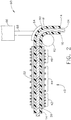
- FIG. 1 shows a composite tube 12 positioned within a bending the apparatus 10 prior to the tube 12 being heated by induction heating and a bend 80 being made being made in the composite tube 12.
- induction heating refers to the process of heating an electrically conductive material by electromagnetic induction through heat generated in the material by eddy currents.
- the composite tube 12 is generally cylindrical and includes fibers positioned within a polymeric matrix.
- the fibers are carbon fibers and are configured to reinforce the polymeric matrix.
- the materials for the fibers can be chosen from one of the following: carbon, glass, polymer, basalt, quartz, metal, and a combination thereof.
- the fibers are oriented circumferentially around the composite tube 12.
- the fibers can be oriented in one of the following forms: braided, woven, in tape form, positioned at 54°, and a combination thereof.
- the polymeric matrix is preferably poly ether ether ketone (PEEK).
- thermoplastics for use as the matrix include: polyphenylsulfone (PPSU), poly phenylene sulfide (PPS), polyetherimde (PEI), nylon, polyester, polypropylene, and a combination thereof.
- PPSU polyphenylsulfone
- PPS poly phenylene sulfide
- PEI polyetherimde
- nylon nylon
- polyester polypropylene
- the dimensions of the composite tube 12 can be as follows: preferably the maximum diameter is about 1.5 inches; and more preferably the maximum diameter is about three quarters of an inch; and even more preferably one half of an inch; and even more preferably one quarter of an inch. It should be appreciated that the maximum diameter can be larger than 1.5 inches.
- the apparatus 10 includes a rigid mandrel 22 that is configured to support the composite tube 12 while the composite tube 12 is being heated. As shown in FIG. 1 , at least a portion of the composite tube 12 is positioned around the rigid mandrel 22.
- the rigid mandrel 22 is configured to support the composite tube 12.
- the rigid mandrel 22 is formed of a metallic material.
- the rigid mandrel 22 can be formed of a conductive material or include a conductive material such that the rigid mandrel 22 can be heated by induction heating. In other embodiments, the rigid mandrel 22 can be formed of a nonconductive material such as a ceramic as will be discussed further below.
- At least a portion of the rigid mandrel 22 and at least a portion of the composite tube 12 surrounding the rigid mandrel 22 are positioned within an induction coil 40.
- the portion of the composite tube 12 that is positioned within the induction coil 40 defines a working region W at the beginning of a bending process as will be described further below. Stated another way, the working region W is the region of the composite tube 12 that will be heated by the induction coil 40 and subsequently bent.
- a sleeve 26 is positioned around the working region W of the composite tube 12.
- the sleeve 26 is operable to provide external support to the composite tube 12 such that the shape and configuration of the composite tube 12 is generally maintained while it is positioned within the induction coil 40.
- the sleeve 26 is nonconductive and therefore is not configured to provide heat during operation of the induction coil 40.
- the sleeve 26 is formed of one of the following: a ceramic, alumina, silica, alumina-silicate, nitrides, carbides, porcelain, refractory, glass, borosilicate, and a combination thereof.
- the rigid mandrel 22 and the sleeve 26 are each configured to ensure that the composite tube 12 is centered.
- the term "centered" refers to the position of the composite tube 12 within the induction coil 40 and with the electromagnetic field generated by the induction coil 40.
- the rigid mandrel 22 is preferably formed of metal and the sleeve 26 is preferably formed of a ceramic.
- either one or both of the rigid mandrel 22 and the sleeve 26 can be formed of one of the following: metal, a metallic material, a conductive material, a nonconductive material containing enough conductive material to be operable to provide heat during induction heating, and a combination thereof. It should be appreciated that both the rigid mandrel 22 and the sleeve 26 are formed of a material that is capable of maintaining its shape throughout the heating process sufficient to support the tube 12.
- At least one of the sleeve 26, the rigid mandrel 22, and the tube 12 must be configured to be operable to be heated by induction coil 40 during induction heating.
- at least one these structures is operable as a heating element and is positioned within the effective region of induction coil 40.
- only the rigid mandrel 22 is utilized to support the composite tube 12 and to provide heat to the work region W of the composite tube 12.
- only the sleeve 26 is utilized to support the composite tube 12 and to provide heat to the work region W of the composite tube 12.
- the induction coil 40 is positioned within a recess or hollow defined within rigid mandrel 22. In some embodiments the induction coil 40 can be positioned within the composite tube 12 such that a sleeve 26 that is positioned outside of the composite tube 12 is configured to be heated by the induction coil 40 thus heating the composite tube 12.
- the composite tube 12 is configured to operate as the heating element.
- the fiber in the composite is configured to be electrically conductive such as carbon or metal.
- the composite tube 12 can be heated directly as a heating element without utilizing rigid tube 22 or the sleeve 26 as the heating element.
- both rigid tube 22 and the sleeve 26 can be a ceramic or another nonconductive material.
- the induction coil 40 is configured to be electrically connected to a power source S and an electrical ground G.
- the induction coil 40 is configured such that when current is passed through it from source S to ground G, heat is generated within the rigid mandrel 22 as will be described further below with regards to the operation the apparatus 10.
- the induction coil 40 includes a plurality of coils or turns 41 that are grouped into a first zone 42, a second zone 44, and a third zone 46.
- each zone includes the same number of the turns 41.
- the total number of the turns 41 within the induction coil 40 is three times the number of the turns 41 in each zone.
- the turn-to-turn spacing is constant within each zone.
- the term "turn-to-turn spacing" refers to the distance between any two adjacent turns 41 within the induction coil 40.
- the turn-to-turn spacing of the first zone 42 is different than that of the adjacent the second zone 44.
- the turn-to-turn spacing of the coils 41 within the first zone 42 and within the third zone 46 is the same.
- an induction coil can be formed to generate a predetermined temperature profile by choosing the number of zones, the turn-to-turn spacing within a zone, and the spacing between zones.
- the configuration of the induction coil 40 can affect a temperature profile. It is believed that the flatter a temperature profile, the more consistent the composite tube 12 will respond to bending. Therefore a flatter temperature profile is desirable. Also, when the temperature profile is flatter and longer, it is easier to maintain the length of work region W of the composite tube 12 within an acceptable temperature range.
- the turn-to-turn spacing should be symmetric, with the largest turn-to-turn spacing occurring in the middle zone or zones.
- curves B and C in FIG. 5 adjustments in turn-to-turn spacing of the coils 41 within the first zone 42, the second zone 44, and a third zone 46 provide different temperature profiles.
- Curve D shown in FIG. 5 represents a heating profile provided by an induction coil with uniform turn-to-turn spacing throughout the length of the induction coil.
- the length of the generally flat temperature profile is preferably at least twice the diameter of the tube 12 to be bent.
- an induction coil 40 can be configured as follows: the number of zones is 3, the number of turns in each zone is 5.
- the turn-to-turn spacing in first zone is .05 inches.
- the turn-to-turn spacing in the second zone is .10 inches.
- the turn-to-turn spacing in the third zone is .05 inches.
- the first zone of 5 turns is of length 0.25" (25% of the total length)
- the second zone of 5 turns is of length 0.5" (50% of the total length)
- the last zone of 5 turns is of length 0.25" (25% of the total length).
- Such a configuration should provide a relatively flat heat profile as indicated by curve A.
- the coil design may be configured such that turn-to-turn spacing is asymmetrical across the zones.
- Such a configuration could be useful when the heat conductive properties are such that heat is generally limited to be conducted axially in only one direction away from the work region W.
- the coil design might include three zones each having five turns.
- Turn-to-turn spacing in the first zone could be .04 inches, and the second zone .06 inches, and in the third zone .1 inches.
- This exemplary embodiment gives a coil with a 1" total length, 3 zones, and 15 turns where the first 5 turns take up the first 20% of the total length, the next 5 turns take up the next 30% of the total length, and the final 5 turns take up the final 50% of the coil.
- specialty induction heating coils may be designed utilizing by varying the number of zones, the number of turns within a zone, the turn-to-turn spacing and the spacing between the zones.
- a predetermined temperature profile can be achieved with the induction coil 40 depending on thermal boundary conditions.
- a bending apparatus 60 is positioned near the induction coil 40.
- the bending apparatus 60 includes a die 62 and a clamp 64.
- Clamp 64 is connected to a hydraulic cylinder 66 by a hydraulic shaft 68.
- the hydraulic cylinder 66 and the hydraulic shaft 68 are configured to be cooperatively engaged such that hydraulic cylinder 66 and hydraulic shaft 68 can be operated by a source of hydraulic power such that hydraulic shaft 68 can extend from and retract into hydraulic cylinder 66. In this manner, clamp 64 and die 62 can be moved relative to each other.
- the bending apparatus 60 is configured to be heated.
- the bending apparatus 60 is generally heated to a temperature near that of the work region W of the composite tube 12 just after the work region W leaves the induction coil 40.
- the temperature of the bending apparatus 60 can be chosen such that cooling rates and physical characteristics of the composite tube 12 are controlled as desired.
- the bending apparatus 60 is also configured such that it can be cooled in a controlled manner. In this fashion, a bend 80 of the composite tube 12 can be cooled from the bending temperature gradually.
- a flexible mandrel 24 extends from an end of the rigid mandrel 22 into the bending apparatus 60.
- the metal is configured to have sufficient flexibility to support the composite tube 12 during formation of a bend 80. More specifically, the flexible mandrel 24 is configured to support the composite tube 12 at work region W while a bend 80 is being formed.
- the flexible mandrel 24 is configured to be flexible and to conduct heat.
- the flexible mandrel 24 is formed of a metal.
- the flexible mandrel 24 can be formed of one of the following: metal, brass, steel, copper, titanium, aluminum, ceramic, copper and aluminum alloy such as Ampco, and a combination thereof.
- the rigid mandrel 22 and the flexible mandrel 24 are configured such that the composite tube 12 can be moved along the rigid mandrel 22 and the flexible mandrel 24 after work region W of composite 14 has been heated.
- the composite tube 12 can be moved such that it is partially on the rigid mandrel 22 and partially on the flexible mandrel 24.
- the composite tube 12 can be moved such that it is not on the rigid mandrel 22 but is at least partially supported by the flexible mandrel 24.
- Steps for providing a bend 80 in the composite tube 12 are as follows: A) positioning the rigid mandrel 22 within the composite tube 12; B) positioning the sleeve 26 such that it surrounds the composite tube 12; C) positioning the composite tube 12 such that at least a portion of the composite tube 12 having the rigid mandrel 22 therein is positioned within the induction coil 40; D) applying current to the induction coil 40; E) heating the rigid mandrel 22; F) heating work region W of the composite tube 12 to a predetermined temperature range, temperatures within the predetermined temperature range being preferably within plus or minus 20°F of a target temperature and more preferably plus or minus 10 °F of the target temperature where the target temperature is greater than glass transition temperature; G) removing work region W from the induction coil 40; H) positioning the composite tube 12 such that at least a portion of work region W is on the flexible mandrel 24; I) heating bending device 60; J) positioning work region W such
- the work region W of the composite tube 12 can be heated by the induction coil 40 and then moved to a position where bending device 60 can act to bend the composite tube 12.
- a bend 80 has been formed in the composite tube 12.
- the step of closing the bending device 60 to bend the composite tube 12 can be performed incrementally. Incremental bending allows the die 62 to stop after the composite tube 12 has been bent a few degrees. Time is provided for the material of the composite tube 12 to relax before a further increment of bending is commenced. In this manner the strain rate associated with bending the composite tube 12 is kept to acceptable levels.
- the composite tube 12 is repositioned if necessary to define a new W which will be the region the new bend 80 is formed in.
- the process described above is repeated such that the new W is heated.
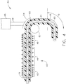
- FIG. 3 shows the composite tube 12 having been repositioned such that new W is positioned within bending device 60 prior to formation of another bend 80.
- FIG. 4 shows the new bend 80 having been formed within the composite tube 12. It should be noted that the bends can be at different angles ⁇ .
- the first bend 80 is formed and moved such that a new region of the composite tube 12 is positioned within the induction coil 40 defining a new work region W. The process is then repeated and can be repeated multiple times for multiple bends. It should be appreciated that the composite tube 12 can be rotated such that the second bend 80 and the first bend 80 extend into different planes. The degree of each bend 80 can be different from other bend 80 is within a single the composite tube 12.
- the rate of heating the step F heating work region W should be controlled as appropriate to allow for the composite tube 12 to be removed from the rigid mandrel 22.
- the metal mandrel expands faster than composite tube when exposed to heat and the rate of heating due to the induction coil 40 should be limited such that the metal mandrel is removable from the composite tube 12 as required in step G removing work region W from the induction coil 40.
- One of the advantages provided by bending a composite tube according to the method as described above is that the length of the composite tube 12 that can be heated, and thus bent, is longer than can be heated according to conventional methods.
- Another of the advantages provided by induction heating according to the method described above is that the temperature of the composite tube can be controlled carefully such that matrix in the composite tubes does not deteriorate as it might when heated to a temperature that is too high.
- Another of the advantages provided by induction heating according to the method described above is that tubes can be bent more quickly than with conventional methods.
Landscapes
- Engineering & Computer Science (AREA)
- Mechanical Engineering (AREA)
- Physics & Mathematics (AREA)
- Electromagnetism (AREA)
- Shaping Of Tube Ends By Bending Or Straightening (AREA)
- Bending Of Plates, Rods, And Pipes (AREA)
- General Induction Heating (AREA)
Claims (13)
- Einrichtung zum Biegen eines Verbundrohrs (12), wobei die Einrichtung umfasst:eine Biegevorrichtung (60)eine Induktionsspule (40), die mehrere Windungen (41) enthält, wobei sich der Windungsabstand mindestens einmal entlang der Länge der Induktionsspule (40) ändert;ein Heizelement (22, 26), das nahe der Induktionsspule (40) positioniert ist;wobei die Induktionsspule (40) so konfiguriert ist, dass das Heizelement (22, 26) zu einer Temperaturerhöhung veranlasst wird.
- Einrichtung zum Biegen nach Anspruch 1, wobei das Heizelement (22, 26) zumindest teilweise innerhalb der Induktionsspule (40) positioniert ist.
- Einrichtung zum Biegen nach Anspruch 2, wobei die Induktionsspule (40) eine erste Zone (42) enthält, die mehrere Windungen (41) enthält, die in einem ersten Windungsabstand positioniert sind;
eine zweite Zone (44), die mehrere Windungen (41) enthält, die in einem zweiten Windungsabstand positioniert sind; und
wobei sich der erste Windungsabstand von dem zweiten Windungsabstand unterscheidet. - Einrichtung zum Biegen nach Anspruch 3, wobei die Induktionsspule (40) eine dritte Zone (46) enthält und wobei die dritte Zone (46) mehrere Windungen (41) enthält, die in einem dritten Windungsabstand positioniert sind; und
wobei sich der dritte Windungsabstand von dem zweiten Windungsabstand unterscheidet. - Einrichtung zum Biegen nach Anspruch 4, wobei der erste Windungsabstand kleiner ist als der zweite Windungsabstand, der kleiner als der dritte Windungsabstand ist.
- Einrichtung zum Biegen nach Anspruch 1, wobei das Heizelement (22, 26) ein starrer Dorn (22) ist, und wobei ein flexibler Dorn (24) konfiguriert ist, um das Verbundrohr (12) von dem starren Dorn (22) aufzunehmen, wobei der flexible Dorn (24) sich in die Biegevorrichtung (60) erstreckt.
- Einrichtung zum Biegen nach Anspruch 1, wobei das Heizelement (26) eine Hülse (26) ist.
- Verfahren zum Biegen eines Verbundrohrs (12) unter Verwendung einer Einrichtung nach Anspruch 1, wobei das Verfahren die folgenden Schritte umfasst:Positionieren des Verbundrohrs (12) derart, dass mindestens ein Abschnitt des Verbundrohrs (12) in der Nähe des Heizelements (22, 26) positioniert ist;Anlegen von Strom an die Induktionsspule (40);Erhitzen des Heizelements (22, 26);Erhitzen eines Arbeitsbereichs W des Verbundrohrs (12);Positionieren des Arbeitsbereichs W derart, dass er zwischen einem Amboss (62) und einem Hammer (64) liegt;Schließen der Biegevorrichtung (60) derart, dass der Arbeitsbereich W zwischen dem Amboss (62) und dem Hammer (64) erfasst wird und das Verbundrohr (12) um den Amboss (62) gebogen wird, wodurch eine Biegung (80) gebildet wird.
- Verfahren zum Biegen eines Verbundrohrs (12) nach Anspruch 8, ferner umfassend den Schritt des
Positionierens eines starren Dorns (22) innerhalb des Verbundrohrs (12). - Verfahren zum Biegen eines Verbundrohrs (12) nach Anspruch 9, ferner umfassend den Schritt des Positionierens der Hülse (26) derart, dass sie einen Abschnitt des Verbundrohrs (12) umgibt.
- Verfahren zum Biegen eines Verbundrohrs (12) nach Anspruch 10, ferner umfassend den Schritt des Positionierens des Verbundrohrs (12) derart, dass mindestens ein Abschnitt des Verbundrohrs (12) mit einem starren Dorn (22) darin innerhalb der Induktionsspule (40) positioniert ist.
- Verfahren zum Biegen eines Verbundrohrs (12) nach Anspruch 11, ferner umfassend den Schritt des Positionierens des Verbundrohrs (12) derart, dass sich mindestens ein Abschnitt des Arbeitsbereichs W auf einem flexiblen Dorn (24) befindet.
- Verfahren zum Biegen eines Verbundrohrs (12) nach Anspruch 8, ferner umfassend den Schritt des Bildens einer zweiten Biegung (80) in dem Verbundrohr (12).
Applications Claiming Priority (1)
| Application Number | Priority Date | Filing Date | Title |
|---|---|---|---|
| US15/047,993 US10427351B2 (en) | 2016-02-19 | 2016-02-19 | Apparatus for induction heating and bending of thermoplastic composite tubes and a method for using same |
Publications (2)
| Publication Number | Publication Date |
|---|---|
| EP3208068A1 EP3208068A1 (de) | 2017-08-23 |
| EP3208068B1 true EP3208068B1 (de) | 2020-09-02 |
Family
ID=58098420
Family Applications (1)
| Application Number | Title | Priority Date | Filing Date |
|---|---|---|---|
| EP17155840.6A Active EP3208068B1 (de) | 2016-02-19 | 2017-02-13 | Vorrichtung zur induktionserwärmung und biegung von thermoplastischen verbundrohren und verfahren zur verwendung davon |
Country Status (5)
| Country | Link |
|---|---|
| US (1) | US10427351B2 (de) |
| EP (1) | EP3208068B1 (de) |
| JP (1) | JP6560275B2 (de) |
| CN (1) | CN107097401B (de) |
| CA (1) | CA2957483C (de) |
Families Citing this family (14)
| Publication number | Priority date | Publication date | Assignee | Title |
|---|---|---|---|---|
| EA202091071A1 (ru) * | 2017-10-31 | 2020-12-08 | Тринити Бэй Эквипмент Холдингс, Ллк | Система и способ нагрева и закругления наматываемой трубы |
| EP4190186A1 (de) | 2018-05-17 | 2023-06-07 | Philip Morris Products S.A. | Aerosolerzeugungsvorrichtung mit verbesserter induktorspule |
| DE102018209353B4 (de) * | 2018-06-12 | 2023-05-11 | Joma-Polytec Gmbh | Verfahren zum Biegen eines Kunststoffrohrs |
| EP3934824A4 (de) * | 2019-03-07 | 2023-05-10 | CarboFix Spine Inc. | Vorrichtungen, anordnungen, kits, systeme und verfahren zum formen von länglichen elementen, die thermoplastische polymere enthalten |
| CN110712360B (zh) * | 2019-09-29 | 2025-03-18 | 亚勒(义乌)自动化科技有限公司 | 泡壳折边机构 |
| CN110948841B (zh) * | 2019-12-18 | 2021-07-30 | 浙江波士特机械有限公司 | 一种尼龙管自动加热成型设备及成型工艺 |
| CN112718980A (zh) * | 2020-12-23 | 2021-04-30 | 凌云工业股份有限公司 | 一种内置钢丝绳外包覆聚氨酯一体铸造式芯子机构 |
| CN113747623A (zh) * | 2021-08-17 | 2021-12-03 | 中国科学院上海光学精密机械研究所 | 一种用于冻融阀放料的中频感应线圈及其使用方法 |
| TWI799106B (zh) * | 2022-01-24 | 2023-04-11 | 滙歐科技開發股份有限公司 | 環狀纖維纏繞方法及其製品 |
| IT202200011720A1 (it) * | 2022-06-03 | 2023-12-03 | E Wenco Srl | Modulo di riscaldamento a temperature differenziali e metodo di riscaldamento a temperature differenziali. |
| DE102022123815A1 (de) * | 2022-09-16 | 2024-03-21 | Wafios Aktiengesellschaft | Biegemaschine für stangenförmiges, nur erwärmt zu biegendes Material |
| CN115228994B (zh) * | 2022-09-20 | 2022-12-13 | 苏州律动游乐设备有限公司 | 一种金属弯头接口的加工方法 |
| DE102023125375A1 (de) * | 2023-09-19 | 2025-03-20 | Wafios Aktiengesellschaft | Biegedorn für thermoplastisches Rohrmaterial, Biegemaschine sowie Verfahren zum Biegen von solchem Rohrmaterial |
| CN120134597A (zh) | 2023-12-11 | 2025-06-13 | 碳固定脊柱公司 | 用于保持包含复合材料的细长元件的截面轮廓形状的装置以及弯曲该细长元件的装置 |
Family Cites Families (25)
| Publication number | Priority date | Publication date | Assignee | Title |
|---|---|---|---|---|
| US4109361A (en) | 1973-07-17 | 1978-08-29 | Hoesch Werke Aktiengesellschaft | Method and arrangement for the production of annular articles |
| DE2555326C3 (de) | 1975-12-05 | 1978-10-19 | Mannesmann Ag, 4000 Duesseldorf | Vorrichtung zum Biegen von Großrohren |
| DE2709996C3 (de) | 1977-03-08 | 1982-01-14 | Hoechst Ag, 6000 Frankfurt | Vorrichtung zum Herstellen eines Rohrbogens aus einem thermoplastischen Kunststoff |
| JPS6016074Y2 (ja) | 1979-03-30 | 1985-05-20 | 住友金属工業株式会社 | 誘導加熱用ワ−クコイル |
| DE3427639A1 (de) | 1984-07-26 | 1986-02-06 | Cojafex B.V., Rotterdam | Verfahren und vorrichtung zum biegen laenglicher werkstuecke, insbesondere rohre |
| JPS63249631A (ja) | 1987-04-06 | 1988-10-17 | Mazda Motor Corp | 繊維強化合成樹脂成形品の製造法 |
| DE3888929T2 (de) * | 1987-06-09 | 1994-07-21 | Toyo Seikan Kaisha Ltd | Verfahren zum erwärmen einer flasche oder eines vorformlings aus thermoplastischem kunststoff und verfahren zum steuern der temperatur einer heizvorrichtung. |
| JPS6469329A (en) | 1987-09-11 | 1989-03-15 | Mitsubishi Heavy Ind Ltd | Bending method of nonmetallic pipe |
| US5176866A (en) * | 1989-02-28 | 1993-01-05 | Asahi Kasei Kogyo Kabushiki Kaisha | Process for producing a resin product having a bent hollow portion and a core usable for the same process |
| US5240542A (en) | 1990-09-06 | 1993-08-31 | The Board Of Trustees Of The Leland Stanford Junior University | Joining of composite materials by induction heating |
| JP3156159B2 (ja) | 1990-10-12 | 2001-04-16 | 株式会社クラレ | Frp補強筋の曲げ加工方法およびその装置 |
| US5422048A (en) * | 1992-09-30 | 1995-06-06 | Tokai Rubber Industries, Ltd. | Method of producing a bent resin tube |
| JPH06190913A (ja) | 1992-09-30 | 1994-07-12 | Tokai Rubber Ind Ltd | 曲り樹脂チューブの製造方法 |
| US5504308A (en) | 1994-06-15 | 1996-04-02 | Kabushikikaisha Fujipula Seiko | Synthetic resin tube for bending use and its bending method |
| GB9820143D0 (en) | 1998-09-17 | 1998-11-11 | Mckechnie Uk Ltd | Improvements in or relating to bending of thermoplastic tubes |
| JP3687439B2 (ja) | 1999-09-29 | 2005-08-24 | コニカミノルタビジネステクノロジーズ株式会社 | 誘導加熱定着装置 |
| JP2001319765A (ja) | 2000-05-12 | 2001-11-16 | Mitsubishi Electric Corp | ロータ加熱装置、ロータの製造方法、電動機および冷凍サイクル |
| US8066841B2 (en) | 2002-05-22 | 2011-11-29 | Woco Avs Gmbh | Method for manufacturing composite systems made of metal polymer shaped parts |
| US20050087910A1 (en) | 2003-10-27 | 2005-04-28 | Fawley Norman C. | Method and apparatus for bending composite reinforced pipe |
| EP1547702B1 (de) * | 2003-12-26 | 2007-07-11 | Calsonic Kansei Corporation | Vorrichtung und Verfahren zum Biegen von Mehrkammerrohren |
| US8017059B2 (en) | 2007-09-13 | 2011-09-13 | The Boeing Company | Composite fabrication apparatus and method |
| US8796600B2 (en) | 2007-11-30 | 2014-08-05 | Honda Motor Co., Ltd. | Induction warming system for fiber composite gas storage cylinders |
| US8657595B2 (en) | 2008-02-26 | 2014-02-25 | Roctool | Device for transforming materials by induction heating |
| DE102010020360B4 (de) | 2010-05-13 | 2016-06-16 | AWS Schäfer Technologie GmbH | Biegemaschine für linke und rechte Biegungen |
| WO2014143762A2 (en) * | 2013-03-15 | 2014-09-18 | Armour Technologies, Inc. | Medical device curving apparatus, system, and method of use |
-
2016
- 2016-02-19 US US15/047,993 patent/US10427351B2/en active Active
-
2017
- 2017-02-09 JP JP2017021835A patent/JP6560275B2/ja not_active Expired - Fee Related
- 2017-02-09 CA CA2957483A patent/CA2957483C/en not_active Expired - Fee Related
- 2017-02-13 EP EP17155840.6A patent/EP3208068B1/de active Active
- 2017-02-17 CN CN201710085954.0A patent/CN107097401B/zh active Active
Non-Patent Citations (1)
| Title |
|---|
| None * |
Also Published As
| Publication number | Publication date |
|---|---|
| US10427351B2 (en) | 2019-10-01 |
| CN107097401A (zh) | 2017-08-29 |
| JP2017144728A (ja) | 2017-08-24 |
| US20170239877A1 (en) | 2017-08-24 |
| CN107097401B (zh) | 2019-10-25 |
| JP6560275B2 (ja) | 2019-08-14 |
| CA2957483A1 (en) | 2017-08-19 |
| EP3208068A1 (de) | 2017-08-23 |
| CA2957483C (en) | 2019-05-21 |
Similar Documents
| Publication | Publication Date | Title |
|---|---|---|
| CA2957483C (en) | An apparatus for induction heating and bending of thermoplastic composite tubes and a method for using same | |
| CN101977744B (zh) | 轮胎硫化机 | |
| EP3804970B1 (de) | Strangziehverfahren und anordnungen zur herstellung eines faserverstärkten verbundwerkstoffprodukts | |
| EP3052803B1 (de) | Intelligenter suszeptor für induktives heizsystem eines aktuators aus einer formgedächtnislegierung (sma) | |
| EP2977166B1 (de) | Einen formgedächtnis-legierungsdorn und ein verfahren zu seiner nutzung | |
| CN109982463B (zh) | 包含具有非磁性金属芯的张紧构件的感应加热单元 | |
| CN103448256B (zh) | 用于制造飞机机身的装置的扇区的致动系统 | |
| US20130270259A1 (en) | Device and method for inductively heating metal components during welding, using a cooled flexible induction element | |
| CN113510211B (zh) | 一种钻杆管体管端加热镦粗连续作业工艺 | |
| CN101195136A (zh) | 一种中频感应加热推制弯头的工艺及其装置 | |
| KR101684904B1 (ko) | 저항재료가 코팅된 형상기억합금 스프링 및 그 제작방법 | |
| CN109109350B (zh) | 用于过程内形成复杂形状刚性复合管的方法 | |
| CN110446280A (zh) | 蛇形折弯空心圆柱体弹性加热器、其加工模具及加工方法 | |
| CN210082607U (zh) | 多层管制作装置 | |
| TW202147375A (zh) | 用於電漿處理設備之射頻(rf)線圈的形成模具及方法 | |
| US20180358158A1 (en) | Solenoid and method for forming a solenoid | |
| CN111570580B (zh) | 用于大直径厚壁管的加热装置及其加热方法 | |
| CN1274337A (zh) | 由预成形件拉成光导纤维的设备和方法 | |
| CZ293471B6 (cs) | Způsob přetváření plášťů plechovek s kompenzací opotřebení tvářecího nástroje a nástroj k přetváření plášťů plechovek | |
| JPH04212833A (ja) | 繊維補強熱可塑性樹脂からなる異形管の製造方法 | |
| JPS5952690B2 (ja) | 大径熱処理鋼管の製造方法 |
Legal Events
| Date | Code | Title | Description |
|---|---|---|---|
| PUAI | Public reference made under article 153(3) epc to a published international application that has entered the european phase |
Free format text: ORIGINAL CODE: 0009012 |
|
| STAA | Information on the status of an ep patent application or granted ep patent |
Free format text: STATUS: THE APPLICATION HAS BEEN PUBLISHED |
|
| AK | Designated contracting states |
Kind code of ref document: A1 Designated state(s): AL AT BE BG CH CY CZ DE DK EE ES FI FR GB GR HR HU IE IS IT LI LT LU LV MC MK MT NL NO PL PT RO RS SE SI SK SM TR |
|
| AX | Request for extension of the european patent |
Extension state: BA ME |
|
| STAA | Information on the status of an ep patent application or granted ep patent |
Free format text: STATUS: REQUEST FOR EXAMINATION WAS MADE |
|
| 17P | Request for examination filed |
Effective date: 20180223 |
|
| RBV | Designated contracting states (corrected) |
Designated state(s): AL AT BE BG CH CY CZ DE DK EE ES FI FR GB GR HR HU IE IS IT LI LT LU LV MC MK MT NL NO PL PT RO RS SE SI SK SM TR |
|
| GRAP | Despatch of communication of intention to grant a patent |
Free format text: ORIGINAL CODE: EPIDOSNIGR1 |
|
| STAA | Information on the status of an ep patent application or granted ep patent |
Free format text: STATUS: GRANT OF PATENT IS INTENDED |
|
| INTG | Intention to grant announced |
Effective date: 20200401 |
|
| GRAS | Grant fee paid |
Free format text: ORIGINAL CODE: EPIDOSNIGR3 |
|
| GRAA | (expected) grant |
Free format text: ORIGINAL CODE: 0009210 |
|
| STAA | Information on the status of an ep patent application or granted ep patent |
Free format text: STATUS: THE PATENT HAS BEEN GRANTED |
|
| AK | Designated contracting states |
Kind code of ref document: B1 Designated state(s): AL AT BE BG CH CY CZ DE DK EE ES FI FR GB GR HR HU IE IS IT LI LT LU LV MC MK MT NL NO PL PT RO RS SE SI SK SM TR |
|
| REG | Reference to a national code |
Ref country code: GB Ref legal event code: FG4D |
|
| REG | Reference to a national code |
Ref country code: AT Ref legal event code: REF Ref document number: 1308331 Country of ref document: AT Kind code of ref document: T Effective date: 20200915 Ref country code: CH Ref legal event code: EP |
|
| REG | Reference to a national code |
Ref country code: DE Ref legal event code: R096 Ref document number: 602017022597 Country of ref document: DE |
|
| REG | Reference to a national code |
Ref country code: IE Ref legal event code: FG4D |
|
| REG | Reference to a national code |
Ref country code: LT Ref legal event code: MG4D |
|
| PG25 | Lapsed in a contracting state [announced via postgrant information from national office to epo] |
Ref country code: NO Free format text: LAPSE BECAUSE OF FAILURE TO SUBMIT A TRANSLATION OF THE DESCRIPTION OR TO PAY THE FEE WITHIN THE PRESCRIBED TIME-LIMIT Effective date: 20201202 Ref country code: GR Free format text: LAPSE BECAUSE OF FAILURE TO SUBMIT A TRANSLATION OF THE DESCRIPTION OR TO PAY THE FEE WITHIN THE PRESCRIBED TIME-LIMIT Effective date: 20201203 Ref country code: FI Free format text: LAPSE BECAUSE OF FAILURE TO SUBMIT A TRANSLATION OF THE DESCRIPTION OR TO PAY THE FEE WITHIN THE PRESCRIBED TIME-LIMIT Effective date: 20200902 Ref country code: SE Free format text: LAPSE BECAUSE OF FAILURE TO SUBMIT A TRANSLATION OF THE DESCRIPTION OR TO PAY THE FEE WITHIN THE PRESCRIBED TIME-LIMIT Effective date: 20200902 Ref country code: BG Free format text: LAPSE BECAUSE OF FAILURE TO SUBMIT A TRANSLATION OF THE DESCRIPTION OR TO PAY THE FEE WITHIN THE PRESCRIBED TIME-LIMIT Effective date: 20201202 Ref country code: LT Free format text: LAPSE BECAUSE OF FAILURE TO SUBMIT A TRANSLATION OF THE DESCRIPTION OR TO PAY THE FEE WITHIN THE PRESCRIBED TIME-LIMIT Effective date: 20200902 Ref country code: HR Free format text: LAPSE BECAUSE OF FAILURE TO SUBMIT A TRANSLATION OF THE DESCRIPTION OR TO PAY THE FEE WITHIN THE PRESCRIBED TIME-LIMIT Effective date: 20200902 |
|
| REG | Reference to a national code |
Ref country code: NL Ref legal event code: MP Effective date: 20200902 |
|
| REG | Reference to a national code |
Ref country code: AT Ref legal event code: MK05 Ref document number: 1308331 Country of ref document: AT Kind code of ref document: T Effective date: 20200902 |
|
| PG25 | Lapsed in a contracting state [announced via postgrant information from national office to epo] |
Ref country code: PL Free format text: LAPSE BECAUSE OF FAILURE TO SUBMIT A TRANSLATION OF THE DESCRIPTION OR TO PAY THE FEE WITHIN THE PRESCRIBED TIME-LIMIT Effective date: 20200902 Ref country code: RS Free format text: LAPSE BECAUSE OF FAILURE TO SUBMIT A TRANSLATION OF THE DESCRIPTION OR TO PAY THE FEE WITHIN THE PRESCRIBED TIME-LIMIT Effective date: 20200902 Ref country code: LV Free format text: LAPSE BECAUSE OF FAILURE TO SUBMIT A TRANSLATION OF THE DESCRIPTION OR TO PAY THE FEE WITHIN THE PRESCRIBED TIME-LIMIT Effective date: 20200902 |
|
| PG25 | Lapsed in a contracting state [announced via postgrant information from national office to epo] |
Ref country code: RO Free format text: LAPSE BECAUSE OF FAILURE TO SUBMIT A TRANSLATION OF THE DESCRIPTION OR TO PAY THE FEE WITHIN THE PRESCRIBED TIME-LIMIT Effective date: 20200902 Ref country code: PT Free format text: LAPSE BECAUSE OF FAILURE TO SUBMIT A TRANSLATION OF THE DESCRIPTION OR TO PAY THE FEE WITHIN THE PRESCRIBED TIME-LIMIT Effective date: 20210104 Ref country code: CZ Free format text: LAPSE BECAUSE OF FAILURE TO SUBMIT A TRANSLATION OF THE DESCRIPTION OR TO PAY THE FEE WITHIN THE PRESCRIBED TIME-LIMIT Effective date: 20200902 Ref country code: EE Free format text: LAPSE BECAUSE OF FAILURE TO SUBMIT A TRANSLATION OF THE DESCRIPTION OR TO PAY THE FEE WITHIN THE PRESCRIBED TIME-LIMIT Effective date: 20200902 Ref country code: SM Free format text: LAPSE BECAUSE OF FAILURE TO SUBMIT A TRANSLATION OF THE DESCRIPTION OR TO PAY THE FEE WITHIN THE PRESCRIBED TIME-LIMIT Effective date: 20200902 |
|
| PG25 | Lapsed in a contracting state [announced via postgrant information from national office to epo] |
Ref country code: ES Free format text: LAPSE BECAUSE OF FAILURE TO SUBMIT A TRANSLATION OF THE DESCRIPTION OR TO PAY THE FEE WITHIN THE PRESCRIBED TIME-LIMIT Effective date: 20200902 Ref country code: AL Free format text: LAPSE BECAUSE OF FAILURE TO SUBMIT A TRANSLATION OF THE DESCRIPTION OR TO PAY THE FEE WITHIN THE PRESCRIBED TIME-LIMIT Effective date: 20200902 Ref country code: AT Free format text: LAPSE BECAUSE OF FAILURE TO SUBMIT A TRANSLATION OF THE DESCRIPTION OR TO PAY THE FEE WITHIN THE PRESCRIBED TIME-LIMIT Effective date: 20200902 Ref country code: IS Free format text: LAPSE BECAUSE OF FAILURE TO SUBMIT A TRANSLATION OF THE DESCRIPTION OR TO PAY THE FEE WITHIN THE PRESCRIBED TIME-LIMIT Effective date: 20210102 |
|
| REG | Reference to a national code |
Ref country code: DE Ref legal event code: R097 Ref document number: 602017022597 Country of ref document: DE |
|
| PG25 | Lapsed in a contracting state [announced via postgrant information from national office to epo] |
Ref country code: SK Free format text: LAPSE BECAUSE OF FAILURE TO SUBMIT A TRANSLATION OF THE DESCRIPTION OR TO PAY THE FEE WITHIN THE PRESCRIBED TIME-LIMIT Effective date: 20200902 |
|
| PLBE | No opposition filed within time limit |
Free format text: ORIGINAL CODE: 0009261 |
|
| STAA | Information on the status of an ep patent application or granted ep patent |
Free format text: STATUS: NO OPPOSITION FILED WITHIN TIME LIMIT |
|
| 26N | No opposition filed |
Effective date: 20210603 |
|
| PG25 | Lapsed in a contracting state [announced via postgrant information from national office to epo] |
Ref country code: DK Free format text: LAPSE BECAUSE OF FAILURE TO SUBMIT A TRANSLATION OF THE DESCRIPTION OR TO PAY THE FEE WITHIN THE PRESCRIBED TIME-LIMIT Effective date: 20200902 Ref country code: SI Free format text: LAPSE BECAUSE OF FAILURE TO SUBMIT A TRANSLATION OF THE DESCRIPTION OR TO PAY THE FEE WITHIN THE PRESCRIBED TIME-LIMIT Effective date: 20200902 |
|
| REG | Reference to a national code |
Ref country code: DE Ref legal event code: R119 Ref document number: 602017022597 Country of ref document: DE |
|
| PG25 | Lapsed in a contracting state [announced via postgrant information from national office to epo] |
Ref country code: MC Free format text: LAPSE BECAUSE OF FAILURE TO SUBMIT A TRANSLATION OF THE DESCRIPTION OR TO PAY THE FEE WITHIN THE PRESCRIBED TIME-LIMIT Effective date: 20200902 |
|
| REG | Reference to a national code |
Ref country code: BE Ref legal event code: MM Effective date: 20210228 |
|
| PG25 | Lapsed in a contracting state [announced via postgrant information from national office to epo] |
Ref country code: CH Free format text: LAPSE BECAUSE OF NON-PAYMENT OF DUE FEES Effective date: 20210228 Ref country code: LI Free format text: LAPSE BECAUSE OF NON-PAYMENT OF DUE FEES Effective date: 20210228 Ref country code: IT Free format text: LAPSE BECAUSE OF FAILURE TO SUBMIT A TRANSLATION OF THE DESCRIPTION OR TO PAY THE FEE WITHIN THE PRESCRIBED TIME-LIMIT Effective date: 20200902 Ref country code: LU Free format text: LAPSE BECAUSE OF NON-PAYMENT OF DUE FEES Effective date: 20210213 |
|
| PG25 | Lapsed in a contracting state [announced via postgrant information from national office to epo] |
Ref country code: DE Free format text: LAPSE BECAUSE OF NON-PAYMENT OF DUE FEES Effective date: 20210901 Ref country code: IE Free format text: LAPSE BECAUSE OF NON-PAYMENT OF DUE FEES Effective date: 20210213 Ref country code: FR Free format text: LAPSE BECAUSE OF NON-PAYMENT OF DUE FEES Effective date: 20210228 |
|
| PG25 | Lapsed in a contracting state [announced via postgrant information from national office to epo] |
Ref country code: BE Free format text: LAPSE BECAUSE OF NON-PAYMENT OF DUE FEES Effective date: 20210228 |
|
| PG25 | Lapsed in a contracting state [announced via postgrant information from national office to epo] |
Ref country code: HU Free format text: LAPSE BECAUSE OF FAILURE TO SUBMIT A TRANSLATION OF THE DESCRIPTION OR TO PAY THE FEE WITHIN THE PRESCRIBED TIME-LIMIT; INVALID AB INITIO Effective date: 20170213 |
|
| P01 | Opt-out of the competence of the unified patent court (upc) registered |
Effective date: 20230414 |
|
| PG25 | Lapsed in a contracting state [announced via postgrant information from national office to epo] |
Ref country code: NL Free format text: LAPSE BECAUSE OF NON-PAYMENT OF DUE FEES Effective date: 20200923 Ref country code: CY Free format text: LAPSE BECAUSE OF FAILURE TO SUBMIT A TRANSLATION OF THE DESCRIPTION OR TO PAY THE FEE WITHIN THE PRESCRIBED TIME-LIMIT Effective date: 20200902 |
|
| PG25 | Lapsed in a contracting state [announced via postgrant information from national office to epo] |
Ref country code: MK Free format text: LAPSE BECAUSE OF FAILURE TO SUBMIT A TRANSLATION OF THE DESCRIPTION OR TO PAY THE FEE WITHIN THE PRESCRIBED TIME-LIMIT Effective date: 20200902 |
|
| PG25 | Lapsed in a contracting state [announced via postgrant information from national office to epo] |
Ref country code: MT Free format text: LAPSE BECAUSE OF FAILURE TO SUBMIT A TRANSLATION OF THE DESCRIPTION OR TO PAY THE FEE WITHIN THE PRESCRIBED TIME-LIMIT Effective date: 20200902 |
|
| PG25 | Lapsed in a contracting state [announced via postgrant information from national office to epo] |
Ref country code: TR Free format text: LAPSE BECAUSE OF FAILURE TO SUBMIT A TRANSLATION OF THE DESCRIPTION OR TO PAY THE FEE WITHIN THE PRESCRIBED TIME-LIMIT Effective date: 20200902 |
|
| PGFP | Annual fee paid to national office [announced via postgrant information from national office to epo] |
Ref country code: GB Payment date: 20260121 Year of fee payment: 10 |