EP3206934B1 - Behältnis - Google Patents
Behältnis Download PDFInfo
- Publication number
- EP3206934B1 EP3206934B1 EP16710131.0A EP16710131A EP3206934B1 EP 3206934 B1 EP3206934 B1 EP 3206934B1 EP 16710131 A EP16710131 A EP 16710131A EP 3206934 B1 EP3206934 B1 EP 3206934B1
- Authority
- EP
- European Patent Office
- Prior art keywords
- receptacle
- guiding rail
- guide
- guide tunnel
- shopping basket
- Prior art date
- Legal status (The legal status is an assumption and is not a legal conclusion. Google has not performed a legal analysis and makes no representation as to the accuracy of the status listed.)
- Active
Links
- 239000004743 Polypropylene Substances 0.000 claims description 8
- 229920001155 polypropylene Polymers 0.000 claims description 8
- -1 polypropylene Polymers 0.000 claims description 7
- 238000002347 injection Methods 0.000 claims description 5
- 239000007924 injection Substances 0.000 claims description 5
- 230000015572 biosynthetic process Effects 0.000 claims description 3
- 239000000463 material Substances 0.000 claims description 3
- 229920002430 Fibre-reinforced plastic Polymers 0.000 claims description 2
- 239000011151 fibre-reinforced plastic Substances 0.000 claims description 2
- 238000003780 insertion Methods 0.000 description 9
- 230000037431 insertion Effects 0.000 description 7
- 238000004519 manufacturing process Methods 0.000 description 6
- 239000004033 plastic Substances 0.000 description 5
- 229920003023 plastic Polymers 0.000 description 5
- 230000000694 effects Effects 0.000 description 4
- 239000004698 Polyethylene Substances 0.000 description 3
- 229910052751 metal Inorganic materials 0.000 description 3
- 239000002184 metal Substances 0.000 description 3
- 229920000573 polyethylene Polymers 0.000 description 3
- 239000004952 Polyamide Substances 0.000 description 2
- 239000003365 glass fiber Substances 0.000 description 2
- 229920002647 polyamide Polymers 0.000 description 2
- IHQKEDIOMGYHEB-UHFFFAOYSA-M sodium dimethylarsinate Chemical class [Na+].C[As](C)([O-])=O IHQKEDIOMGYHEB-UHFFFAOYSA-M 0.000 description 2
- 238000003466 welding Methods 0.000 description 2
- 229910000831 Steel Inorganic materials 0.000 description 1
- 238000009825 accumulation Methods 0.000 description 1
- 229910052782 aluminium Inorganic materials 0.000 description 1
- XAGFODPZIPBFFR-UHFFFAOYSA-N aluminium Chemical compound [Al] XAGFODPZIPBFFR-UHFFFAOYSA-N 0.000 description 1
- 238000005452 bending Methods 0.000 description 1
- 238000000605 extraction Methods 0.000 description 1
- 230000002349 favourable effect Effects 0.000 description 1
- 239000000835 fiber Substances 0.000 description 1
- 239000011521 glass Substances 0.000 description 1
- 238000001746 injection moulding Methods 0.000 description 1
- 230000002093 peripheral effect Effects 0.000 description 1
- 230000002787 reinforcement Effects 0.000 description 1
- 238000007493 shaping process Methods 0.000 description 1
- 239000007858 starting material Substances 0.000 description 1
- 239000010959 steel Substances 0.000 description 1
Images


Classifications
-
- B—PERFORMING OPERATIONS; TRANSPORTING
- B62—LAND VEHICLES FOR TRAVELLING OTHERWISE THAN ON RAILS
- B62B—HAND-PROPELLED VEHICLES, e.g. HAND CARTS OR PERAMBULATORS; SLEDGES
- B62B1/00—Hand carts having only one axis carrying one or more transport wheels; Equipment therefor
- B62B1/02—Hand carts having only one axis carrying one or more transport wheels; Equipment therefor in which the wheel axis is disposed between the load and the handles
- B62B1/04—Hand carts having only one axis carrying one or more transport wheels; Equipment therefor in which the wheel axis is disposed between the load and the handles involving parts being adjustable, collapsible, attachable, detachable, or convertible
- B62B1/042—Hand carts having only one axis carrying one or more transport wheels; Equipment therefor in which the wheel axis is disposed between the load and the handles involving parts being adjustable, collapsible, attachable, detachable, or convertible foldable
-
- B—PERFORMING OPERATIONS; TRANSPORTING
- B62—LAND VEHICLES FOR TRAVELLING OTHERWISE THAN ON RAILS
- B62B—HAND-PROPELLED VEHICLES, e.g. HAND CARTS OR PERAMBULATORS; SLEDGES
- B62B1/00—Hand carts having only one axis carrying one or more transport wheels; Equipment therefor
- B62B1/006—Hand carts having only one axis carrying one or more transport wheels; Equipment therefor being vertically stackable with each other
-
- B—PERFORMING OPERATIONS; TRANSPORTING
- B62—LAND VEHICLES FOR TRAVELLING OTHERWISE THAN ON RAILS
- B62B—HAND-PROPELLED VEHICLES, e.g. HAND CARTS OR PERAMBULATORS; SLEDGES
- B62B1/00—Hand carts having only one axis carrying one or more transport wheels; Equipment therefor
- B62B1/02—Hand carts having only one axis carrying one or more transport wheels; Equipment therefor in which the wheel axis is disposed between the load and the handles
- B62B1/04—Hand carts having only one axis carrying one or more transport wheels; Equipment therefor in which the wheel axis is disposed between the load and the handles involving parts being adjustable, collapsible, attachable, detachable, or convertible
-
- B—PERFORMING OPERATIONS; TRANSPORTING
- B62—LAND VEHICLES FOR TRAVELLING OTHERWISE THAN ON RAILS
- B62B—HAND-PROPELLED VEHICLES, e.g. HAND CARTS OR PERAMBULATORS; SLEDGES
- B62B1/00—Hand carts having only one axis carrying one or more transport wheels; Equipment therefor
- B62B1/10—Hand carts having only one axis carrying one or more transport wheels; Equipment therefor in which the load is intended to be transferred totally to the wheels
- B62B1/12—Hand carts having only one axis carrying one or more transport wheels; Equipment therefor in which the load is intended to be transferred totally to the wheels involving parts being adjustable, collapsible, attachable, detachable, or convertible
- B62B1/125—Hand carts having only one axis carrying one or more transport wheels; Equipment therefor in which the load is intended to be transferred totally to the wheels involving parts being adjustable, collapsible, attachable, detachable, or convertible by means of telescoping elements
-
- B—PERFORMING OPERATIONS; TRANSPORTING
- B62—LAND VEHICLES FOR TRAVELLING OTHERWISE THAN ON RAILS
- B62B—HAND-PROPELLED VEHICLES, e.g. HAND CARTS OR PERAMBULATORS; SLEDGES
- B62B5/00—Accessories or details specially adapted for hand carts
- B62B5/06—Hand moving equipment, e.g. handle bars
- B62B5/062—Hand moving equipment, e.g. handle bars elastically mounted, e.g. for wheelbarrows
-
- B—PERFORMING OPERATIONS; TRANSPORTING
- B62—LAND VEHICLES FOR TRAVELLING OTHERWISE THAN ON RAILS
- B62B—HAND-PROPELLED VEHICLES, e.g. HAND CARTS OR PERAMBULATORS; SLEDGES
- B62B5/00—Accessories or details specially adapted for hand carts
- B62B5/06—Hand moving equipment, e.g. handle bars
- B62B5/067—Stowable or retractable handle bars
-
- B—PERFORMING OPERATIONS; TRANSPORTING
- B62—LAND VEHICLES FOR TRAVELLING OTHERWISE THAN ON RAILS
- B62B—HAND-PROPELLED VEHICLES, e.g. HAND CARTS OR PERAMBULATORS; SLEDGES
- B62B2501/00—Manufacturing; Constructional features
- B62B2501/06—Materials used
- B62B2501/065—Plastics
Definitions
- the present invention relates to a container, in particular a shopping basket, having a bottom and a peripheral side wall adjoining the bottom, wherein the bottom and side wall define an inner region of the shopping basket and wherein the shopping basket is designed to be rollable.
- Such containers in particular shopping baskets are already known from the prior art, which can be pulled by the user behind him by means of a pull handle.
- a rollable shopping basket known, in which a U-shaped pull handle is guided in each edge-side guide tunnels the shopping basket and it is added extendable.
- a rollable shopping basket which has a pull handle with a telescopic, multi-part guide rail, which is also received and guided in a guide portion of the shopping basket.
- the EP 2 167 366 B1 discloses a rollable shopping basket in which a pull handle is hinged at the upper edge of the side wall defining the opening of the interior area. This pull handle can be pivoted from a rest position to a pull position, wherein in the pull position, the pull handle protrudes from the shopping basket.
- the WO 2009/151348 A1 discloses a container according to the preamble of claim 1.
- a container with the features of claim 1. Thereafter, it is provided that a container is provided with a bottom and a subsequent to the ground, circumferential side wall, the bottom and side wall define an inner region of the container, wherein the container is designed rollable, wherein the container further comprises a pull handle with a guide rail and a handle and wherein in a region of the side wall a guide tunnel for guiding and at least partially receiving the guide rail of the pull handle is provided and wherein the guide rail has at least one latching element, the rises out of an outer surface of the guide slips and prevents complete removal of the guide rail from the guide tunnel in the assembled state of the pull handle.
- the invention is based on the idea to simplify a container such as a shopping basket or its assembly to the effect that during assembly, the guide rail only needs to be used only in the guide tunnel and after insertion complete withdrawal of the guide rail by providing the at least one locking element can be prevented.
- the guide tunnel or receiving tunnel on the container or shopping basket for the pull handle and the execution of the at least one latching element on the handle be constructed so that the assembly of the pull handle as a whole (one or more parts) is possible.
- the pull handle is forcibly pushed through the guide tunnel or receiving tunnel on the basket during assembly and secured after the implementation before removal or before pulling out of the guide tunnel, namely by the latching means of the locking element.
- the convex, outer tunnel wall can deform temporarily when inserting the pull handle and as soon as the locking element of the handle is immersed through the guide tunnel, it jumps convex, outer tunnel wall back and thus permanently locks the removal of the handle.
- the container is designed to be stackable.
- the guide rail is made in one piece. As a result, the production of the guide rail is simplified.
- the pull handle is made in one piece. As a result, assembly steps are avoided in connection with the assembly of the pull handle, whereby also the production can be simplified.
- the pull handle and the guide rail are each separate components. This may be necessary, for example, if experience has shown that the pull handle is subjected to high loads and therefore the pull handle should be replaced after a certain period of use.
- An interchangeability of the pull handle is in such an embodiment in the pull handle and guide rail are each separate components, easily possible.
- the individual parts of the pull handle can be glued together, screwed and / or clipped.
- the pull handle consists of a separate handle, a guide profile and a latching part, which is passed through the guide tunnel and carries the latching element consists.
- the handle and / or the Verrastteil can be designed as plastic parts.
- the guide profile may for example be a plastic part or a metal component, e.g. be made of an aluminum extruded profile.
- the pull handle from two half-shells and this by e.g. Ultrasonic welding or laser welding to connect with each other.
- container, bottom, side wall and guide rail and handle are made of plastic.
- the container or the basket made of polypropylene (PP), in particular unreinforced polypropylene may be formed. It is also conceivable to use polyethylene (PE), in particular unreinforced polyethylene.
- PP polypropylene
- PE polyethylene
- the container may be formed as an injection molded part.
- the handle or the pull handle can be made of fiber-reinforced plastic. It is conceivable, for example, that a polyamide (PA) is selected as the plastic, for example PA6 or PA66.
- the fiber reinforcement can be done for example by glass fiber. It is conceivable, in particular, that glass fiber-reinforced PA6 is used as the starting material.
- the handle or the pull handle can be designed as an injection molded part.
- the container is rollable, for example, two rollers may be provided, e.g. can be arranged on the rear side based on the driving condition of the container.
- the axis of the roll can be a metal axis. It is conceivable in this context that the axis is the only metal component of the container.
- the latching element is integrally formed.
- the guide rail can be made easier and corresponding assembly steps can be saved.
- the latching element is wedge-shaped.
- the locking element is oriented such that the flattening of the wedge shape of the locking element is oriented in the direction of insertion of the guide rail of the pull handle, so that when inserting the pull handle in the guide tunnel, the locking element due to its wedge shape expands the guide tunnel accordingly and after the passage of the locking element through the opening of the guide tunnel, the wall of the guide tunnel springs back again.
- the pull handle is no longer pulled out of the guide tunnel due to the shape of the locking element, since the protruding part of the locking element prevents withdrawal from the guide tunnel and the emerging part of the wedge-shaped locking element a kind Stop or approach forms, which abuts against the wall of the guide tunnel and thereby prevents withdrawal.
- the guide rail has two broad sides with a width which is twice as large as the depth of the guide rail. It is conceivable, for example, that the guide rail has a cross-section which is substantially oval or rectangular. As a result, a comparatively favorable area moment of inertia of the cross section is achieved, as a result of which the guide rail is mechanically stable and also comparatively torsionally rigid and well protected against bending in the direction of the broad sides. Such a design also allows only a single guide rail to be provided which nevertheless provides sufficient stability. It is further provided that the locking element is arranged on a broad side. This makes it possible that only a single locking element must be provided.
- the locking element is arranged such that the deformation force exerted by the locking element when inserting the pull handle in the guide tunnel can be relatively uniformly introduced into the walls of the guide tunnel. A gentle insertion of the pull handle in the guide tunnel is thereby possible.
- At least one latching element is provided on the guide rail, by means of which the pull handle in the assembled state of the shopping basket in an extended position can be latched.
- the at least one latching element is arranged sprung.
- the latching element is arranged on a spring bar. This makes it easy to recapture the pull handle from the locked extended position in the guide tunnel, namely, that the spring resistance is overcome.
- parallel spring webs are provided on both sides of a wide side of the guide rail, on each of which a latching element is arranged.
- Such a latching element may for example be wedge-shaped.
- the latching element in any embodiment is wedge-shaped or button-shaped or hemispherical or otherwise suitably shaped.
- At least one further latching element is provided, which is arranged unsprung on the guide rail.
- the further unsprung latching element is arranged centrally on a broad side, in particular above the latching element, on the guide rail.
- the arrangement on the broad side it is possible that a wall of the guide tunnel is elastically pushed during insertion of the guide rail outwardly by the shape of the latching element, that the pull handle can slide through the guide tunnel in the recessed position of the guide rail.
- the latching element has two inclined surfaces, which facilitate the extraction of the guide rail from the guide tunnel and the insertion of the guide rail in the guide tunnel.
- the guide tunnel has at least one recess in which the latching element can be latched. Through the recess, a counterpart can be provided, in which the latching element can engage. As a result, a reliable locking can be easily achieved.
- the guide tunnel has at least one shape in which the latching element can be engaged.
- Forming can be easily achieved that in the assembled state of the pull handle complete withdrawal of the guide rail can be prevented from the guide tunnel or is.
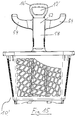
- a further auffädelbarer on the pull handle attachment is provided by means of which an additional basket can be kept. If necessary, a larger amount of goods can be transported with the container by the additional basket, since additional goods can be placed in the additional basket.
- the article has, for example, two support arms on which the additional basket can be held.
- the attachment can be guided with a tower guide tunnel on the guide rail of the pull handle.
- the guide rail is passed through the guide tunnel.
- a further attachable to the guide rail attachment rail can be provided by means of which an additional basket can be kept. This makes it easy to retrofit existing containers to the effect that the containers can be provided with additional baskets.
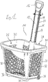
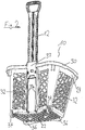
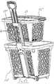
- FIG. 1 shows a perspective view of an inventive container 10 in the embodiment as a shopping basket 10 with a pull handle 12 in the pulled-out state.
- the shopping basket 10 is designed as an injection molded part, wherein the shopping basket 10 is made of unreinforced polypropylene.
- the shopping basket 10 is stackable.
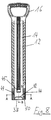
- the pull handle 12 has a guide rail 14 and a handle 16.
- the pull handle 12 is made in one piece.
- the pull handle 12 is made of glass fiber reinforced PA6 and as an injection molded part.
- Materialaus traditions 15 are provided on both narrow sides of the guide rail 14 . These material recesses 15 serve to avoid accumulation of material and to simplify the production by injection molding.
- handle 16 and the guide rail 14 are separate components, which are designed, for example, nestable.
- the handle 16 is made in one piece.
- the guide rail 14 can also be made in one piece.
- the cross section of the guide rail 14 is designed such that it has a broad side 18 (end face 18) with a width b (see FIG. 1 ) and a narrow side 20 having a depth t (see FIG. 3 and FIG. 4 ).
- the broad side 18 or end face 18 may be e.g. be printed.
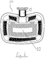
- the shopping basket 10 itself has a bottom 22 (see FIG. 6 ) and a subsequent to the bottom 22 circumferential side wall 24.
- the bottom 22 and the side wall 24 include an interior region 26 of the shopping basket 10 a.
- the inner region 26 itself is accessible via an opening 28 which is bounded on the opposite side of the bottom 22 by the edge 30 of the side wall 24.
- the side wall 24 and also the bottom 22 are provided with grid structures 32. In principle, however, it is also conceivable that the side wall 24 and / or the bottom 22 are closed.
- rollers 34 are attached to a longitudinal side of the bottom.
- support ribs 36 are provided on the opposite longitudinal side of the bottom 22.
- the shopping basket 10 stands on the rollers 34 and the support ribs 36, while it is rollable in the driving condition on the rollers 34.
- a guide tunnel 37 for guiding and at least partially receiving the guide rail 14 of the pull handle 12 is provided.
- all components of the shopping basket 10 are made of plastic, with the exception of the axis (not shown in detail) for the rollers 34 of the shopping basket 10.
- This axis can be made for example of steel.
- the guide tunnel 37 is disposed on the outside of the back of the side wall 24 and is located there in the upper third or quarter of the back of the side wall 24.
- the length of the guide tunnel 37 is about one fifth to about a quarter of the height of the side wall 24th
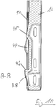
- the cross section of the guide tunnel 37 is in FIG. 11b can be seen (section cut CC see FIG. 11a ).
- the cross section of the guide tunnel 37 has a slightly curved or convex shape.
- the guide rail 14 has at its in the assembled state the bottom 22 facing the end (or at its end remote from the handle 16) a wedge-shaped locking element 38 (see, eg FIG. 5 and FIG. 7 ) that rises obliquely from the broad side 18 of the guide rail 14, in such a way that the highest elevation of the locking element 38 faces the handle 16 and there forms a locking projection 42.
- the inclined surface of the locking element 38 runs in the surface of the guide rail.
- the latching elements 44 are sprung latching elements 44, which are each arranged centrally on a spring bar 50.
- the guide tunnel 37 as a counterpart or as a stop for the locking element 38 has a formation 49, on which the locking element 38 can be stopped.
- the function of the latching element 38 can be described as follows: When inserting the pull handle 12, the locking element 38 presses the outer wall of the guide tunnel 37 to the outside, so that the guide rail 14 and the locking element 38 having a larger cross section than the opening cross section of the guide tunnel 37 can pass through the guide tunnel 37.
- the guide rail 14 is pulled by pulling the pull handle 12 from the guide tunnel 37 against the guide tunnel 37, so the locking element abuts against the projection 49 of the guide tunnel 37 and prevents complete pulling out of the pull handle 12th
- the latching element 38 is provided in the contact region with a surface which is parallel to the shaping 49 and which is wedge-shaped. Thereby, an additional clamping effect can be achieved, so that the pulling forces can be increased on the pull handle 12, so that the pull handle 12 and guide tunnel 37 can be clamped together even better.
- the curved or convex shape of the cross section of the guide tunnel 37 causes the wall of the guide tunnel 37 with the recesses 46, 48, also called the rear wall of the guide tunnel 37, as a leaf spring acts. This is particularly advantageous for the realization of the latching and snap system of the shopping basket 10.
- the shopping basket 10 can not only be pulled, but also pushed.
- FIGS. 2 to 11 Further views of the shopping basket 10 are as described above.
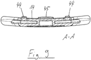
- the sectional view according to FIG. 4 as well as the representation of the sections AA and BB (cut see FIG. 8 ) in the Figures 9 and 10 shows in detail how the locking element 38 and the latching elements 44, 45 are constructed.
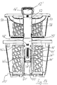
- FIGS. 12 to 16 shows a further embodiment of a shopping basket 10 'according to the invention, which has all the structural and functional features of the shopping basket 10 and its advantages.
- the shopping basket 10 has a threaded on the pull handle 12' essay 52, such as from the FIGS. 15 and 16 seen, two support arms 54, on which an additional basket 56 can be held.
- the attachment 52 is guided with an attachment guide tunnel 58 on the guide rail 14 'of the pull handle 12'.
- FIG. 15 in the retracted state of the pull handle 12 'of the handle 16' shut down to the entrance of the tower guide tunnel 58 and sits on its edge.
- FIGS. 17 to 21 is a further embodiment of a container according to the invention 10 "shown, which has all the structural and functional features and the associated advantages as in the Figures 1 to 11b described embodiment.
- a top rail 60 are provided for attachment to the guide rail 14 "and an additional basket 56".
- the additional basket 56 is identical to the additional basket 56, as in connection with the in the FIGS. 12 to 16 shown embodiment is visible.
- the attachment rail 60 has a central web 62, which has the width b of the guide rail 14 "substantially.
- a respective side web 64 rises.
- the central web 62 and the side webs 64 form a C-shaped profile.
- a guide wing 66 is provided in each case, which can serve for additional support of the additional basket 56 ".
- the attachment rail 60 can be clipped onto the guide rail 14 "and in the in FIG. 17 shown configuration on the extended guide rail 14 "clipped in.
- the center web 62 and the side webs 64 engage around the guide rail 14".
- guide pins 70 are provided, wherein on each guide wing 66 in the side facing away from the attachment pin 68 part of the guide wing 66 each have a guide pin 70 is provided. These guide pins 70 pass through the grid structures of the additional basket 56 "and thereby stabilize the additional basket 56" suspended on the attachment pin 68.
- the lower edge of the top rail 60 sits directly on the upper edge of the guide tunnel 37 "(see. FIG. 20 ), so that over this the weight of the additional basket 56 "can be introduced into the shopping basket 10".
Description
- Die vorliegende Erfindung betrifft ein Behältnis, insbesondere einen Einkaufskorb, mit einem Boden und einer an den Boden anschließenden umlaufenden Seitenwandung, wobei Boden und Seitenwandung einen Innenbereich des Einkaufskorbs begrenzen und wobei der Einkaufskorb rollbar ausgeführt ist.
- Aus dem Stand der Technik sind bereits derartige Behältnisse, insbesondere Einkaufskörbe bekannt, die mittels eines Ziehgriffes durch den Nutzer hinter sich her gezogen werden können.
- So ist beispielsweise aus der
ES 2 352 776 B1 - Des Weiteren ist aus der
EP 1 834 539 A1 ein ziehbarer, rollbarer Einkaufskorb bekannt, bei dem ein u-förmiger Ziehgriff mit zwei Holmen in der Seitenwandung des Einkaufskorbes geführt und darin ausziehbar aufgenommen ist. - Aus der
FR 2 906 212 B1 - Die
EP 2 167 366 B1 offenbart einen rollbaren Einkaufskorb, bei dem am oberen Rand der Seitenwandung, die die Öffnung des Innenbereichs begrenzt, klappbar ein Ziehgriff befestigt ist. Dieser Ziehgriff kann von einer Ruheposition in eine Ziehposition verschwenkt werden, wobei in der Ziehposition der Ziehgriff vom Einkaufskorb absteht. - Ferner ist aus der
WO 2014/118414 A1 ein rollbarer Einkaufskorb bekannt, der einen aufsteckbaren, U-förmigen Ziehgriff aufweist. - Die
WO 2009/151348 A1 offenbart ein Behältnis gemäß dem Oberbegriff von Anspruch 1. - Es ist die Aufgabe der vorliegenden Erfindung, ein Behältnis der eingangs genannten Art in vorteilhafter Weise weiterzubilden, insbesondere dahingehend, dass die Montage des Ziehgriffs zum Behältnis vereinfacht, eine Mehrteiligkeit des Griffes nach Möglichkeit vermieden wird und nachträgliche Montageschritte entfallen können. Darüber hinaus soll eine Verringerung der Investitionskosten und eine Reduzierung der Herstellkosten erreicht werden.
- Diese Aufgabe wird erfindungsgemäß gelöst durch ein Behältnis mit den Merkmalen des Anspruchs 1. Danach ist vorgesehen, dass ein Behältnis mit einem Boden und einer an den Boden anschließenden, umlaufenden Seitenwandung versehen ist, wobei Boden und Seitenwandung einen Innenbereich des Behältnisses begrenzen, wobei das Behältnis rollbar ausgeführt ist, wobei das Behältnis weiter einen Ziehgriff mit einer Führungsschiene und einen Handgriff aufweist und wobei in einem Bereich der Seitenwandung ein Führungstunnel für die Führung und wenigstens teilweisen Aufnahme der Führungsschiene des Ziehgriffs vorgesehen ist und wobei die Führungsschiene wenigstens ein Rastelement aufweist, das sich aus einer Außenfläche der Führungsscheine heraus erhebt und im montierten Zustand des Ziehgriffs ein vollständiges Herausziehen der Führungsschiene aus dem Führungstunnel verhindert.
- Die Erfindung basiert auf dem Grundgedanken, ein Behältnis wie einen Einkaufskorb bzw. dessen Montage dahingehend zu vereinfachen, dass bei der Montage die Führungsschiene lediglich nur in den Führungstunnel eingesetzt werden muss und nach dem Einsetzen ein vollständiges Herausziehen der Führungsschiene durch das Vorsehen des wenigstens einen Rastelementes verhindert werden kann. Insbesondere kann der Führungstunnel bzw. Aufnahmetunnel am Behältnis bzw. Einkaufskorb für den Ziehgriff und die Ausführung des wenigstens einen Verrastungselements am Griff so konstruiert sein, dass die Montage des Ziehgriffes als Ganzes (einteilig oder mehrteilig) ermöglicht wird. Der Ziehgriff wird bei der Montage zwangsweise durch den Führungstunnel bzw. Aufnahmetunnel am Korb hindurchgedrückt und nach der Durchführung vor der Entnahme bzw. vor dem Herausziehen aus dem Führungstunnel gesichert, nämlich durch die Verrastung mittels des Rastelements. So kann sich beispielsweise die konvexe, außenliegende Tunnelwand temporär beim Einschieben des Ziehgriffes verformen und sobald das Rastelement des Griffes durch den Führungstunnel hindurchgetaucht ist, springt diese konvexe, außenliegende Tunnelwand wieder zurück und sperrt somit dauerhaft die Entnahme des Griffes.
- Dadurch wird es möglich, eine Mehrteiligkeit des Griffes nach Möglichkeit entfallen zu lassen und auch nachträgliche Montageschritte zu vermeiden. Insbesondere ist eine Verringerung der Investitionskosten und eine Reduzierung der Herstellkosten möglich.
- Grundsätzlich kann vorgesehen sein, dass das Behältnis stapelbar ausgeführt ist.
- Des Weiteren kann vorgesehen sein, dass die Führungsschiene einstückig ausgeführt ist. Hierdurch wird die Herstellung der Führungsschiene vereinfacht.
- Denkbar ist weiter, dass der Ziehgriff einstückig ausgeführt ist. Dadurch werden Montageschritte im Zusammenhang mit der Montage des Ziehgriffes vermieden, wodurch ebenfalls die Herstellung vereinfacht werden kann.
- Grundsätzlich denkbar ist aber auch, dass der Ziehgriff und die Führungsschiene jeweils gesonderte Bauteile sind. Dies kann beispielsweise erforderlich sein, wenn der Ziehgriff erfahrungsgemäß großen Belastungen ausgesetzt ist und deshalb nach einer gewissen Lebensdauer der Ziehgriff ausgetauscht werden sollte. Eine Austauschbarkeit des Ziehgriffes ist in einer derartigen Ausführungsform, in der Ziehgriff und Führungsschiene jeweils gesonderte Bauteile sind, einfach möglich. Die Einzelteile des Ziehgriffs können miteinander verklebt, verschraubt und/oder verklipst werden.
- Beispielsweise ist möglich, dass der Ziehgriff aus einem gesonderten Handgriff, einem Führungsprofil und einem Verrastteil, das durch den Führungstunnel hindurchgeführt wird und das Rastelement trägt, besteht. Der Handgriff und/oder das Verrastteil können als Kunststoffteile ausgeführt sein. Das Führungsprofil kann beispielsweise ein Kunststoffteil oder auch ein Metallbauteil sein, z.B. aus einem Aluminiumstrangpressprofil gefertigt sein.
- Denkbar ist auch, den Ziehgriff aus zwei Halbschalen zu fertigen und diese durch z.B. Ultraschallschweißen oder Laserschweißen miteinander zu verbinden.
- Insbesondere ist denkbar, dass Behältnis, Boden, Seitenwandung sowie Führungsschiene und Handgriff aus Kunststoff ausgeführt sind.
- Dabei kann das Behältnis bzw. der Korb aus Polypropylen (PP), insbesondere unverstärktem Polypropylen ausgebildet sein. Denkbar ist auch, Polyethylen (PE), insbesondere unverstärktes Polyethylen zu verwenden.
- Das Behältnis kann als Spritzgussteil ausgebildet sein.
- Der Handgriff oder der Ziehgriff kann aus faserverstärktem Kunststoff bestehen. Denkbar ist beispielsweise, dass als Kunststoff ein Polyamid (PA) gewählt wird, beispielsweise PA6 oder PA66. Die Faserverstärkung kann beispielsweise durch Glasfaser erfolgen. Denkbar ist insbesondere, dass als Ausgangswerkstoff glasfaserverstärktes PA6 verwendet wird. Der Handgriff oder der Ziehgriff kann als Spritzgussteil ausgeführt sein.
- Das Behältnis ist rollbar ausgeführt, wobei beispielsweise zwei Rollen vorgesehen sein, die z.B. bezogen auf den Fahrzustand des Behältnisses rückseitig angeordnet sein können. Die Achse der Rolle kann eine Achse aus Metall sein. Denkbar ist in diesem Zusammenhang, dass die Achse das einzige Bauelement aus Metall des Behältnisses ist.
- Des Weiteren ist möglich, dass das Rastelement einstückig ausgebildet ist. Dadurch kann die Führungsschiene einfacher hergestellt werden und entsprechende Montageschritte können eingespart werden.
- Ferner kann vorgesehen sein, dass das Rastelement keilförmig ausgebildet ist. In diesem Zusammenhang ist insbesondere denkbar, dass das Rastelement derart ausgerichtet ist, dass die Abflachung der Keilform des Rastelements in der Einsetzrichtung der Führungsschiene des Ziehgriffs orientiert ist, so dass beim Einsetzen des Ziehgriffs in den Führungstunnel das Rastelement aufgrund seiner Keilform den Führungstunnel entsprechend aufweitet und nach dem Hindurchtreten des Rastelements durch die Öffnung des Führungstunnels die Wandung des Führungstunnels wieder zurückspringt. Dadurch ist der Ziehgriff aufgrund der Form des Rastelements nicht mehr aus dem Führungstunnel herausziehbar, da der hervorspringende Teil des Rastelements ein Herausziehen aus dem Führungstunnel verhindert und der heraustretende Teil des keilförmigen Rastelements eine Art Anschlag bzw. Ansatz bildet, der gegen die Wand des Führungstunnels anschlägt und hierdurch ein Herausziehen verhindert.
- Außerdem kann vorgesehen sein, dass die Führungsschiene zwei Breitseiten mit einer Breite aufweist, die jeweils doppelt so groß ist, wie die Tiefe der Führungsschiene. Denkbar ist beispielsweise, dass die Führungsschiene einen Querschnitt aufweist, der im Wesentlichen oval oder rechteckig ist. Dadurch wird ein vergleichsweise günstiges Flächenträgheitsmoment des Querschnitts erreicht, wodurch die Führungsschiene mechanisch stabil und auch vergleichsweise verwindungssteif sowie gegen durch Biegung in Richtung der Breitseiten gut geschützt ist. Ein derartiges Design erlaubt es auch, dass lediglich eine einzige Führungsschiene vorgesehen ist, die trotzdem eine ausreichende Stabilität bereitstellt. Weiter ist vorgesehen, dass das Rastelement auf einer Breitseite angeordnet ist. Dadurch wird es möglich, dass lediglich ein einziges Rastelement vorgesehen sein muss. Insbesondere ist weiter auch in diesem Zusammenhang möglich, dass das Rastelement derart angeordnet ist, dass die vom Rastelement ausgeübte Verformungskraft beim Einsetzen des Ziehgriffs in den Führungstunnel vergleichsweise gleichmäßig in die Wandungen des Führungstunnels eingeleitet werden kann. Ein schonendes Einsetzen des Ziehgriffs in den Führungstunnel wird hierdurch möglich.
- Darüber hinaus ist vorgesehen, dass auf der Führungsschiene wenigstens ein Einrastelement vorgesehen ist, mittels dessen der Ziehgriff im montierten Zustand des Einkaufskorbs in einer ausgezogenen Position einrastbar ist. Durch den Umstand, dass der Ziehgriff im montierten Zustand des Einkaufskorbs in einer ausgezogenen Position einrastbar ist, ist es möglich, den Einkaufskorb nicht nur ziehen zu können, sondern diesen auch zu schieben. Dies kann beim Manövrieren des Einkaufskorbs von großem Vorteil sein, insbesondere dann, wenn man sich in engen Gassen innerhalb eines Einkaufsladens befindet. Durch das Vorsehen einer ausgezogenen Position, in der der Ziehgriff einrastbar ist, wird verhindert, dass beim Schieben des Behältnisses bzw. Einkaufskorbs der Ziehgriff in den Führungstunnel unabsichtlich hineingleitet und hierdurch wieder im Führungstunnel versenkt wird.
- Insbesondere kann vorgesehen sein, dass das wenigstens eine Einrastelement gefedert angeordnet ist. Insbesondere kann vorgesehen sein, dass das Einrastelement auf einem Federsteg angeordnet ist. Dadurch wird es einfach möglich, den Ziehgriff aus der eingerasteten ausgezogenen Position wieder im Führungstunnel zu versenken, nämlich dadurch, dass der Federwiderstand überwunden wird. Insbesondere ist in diesem Zusammenhang denkbar, dass auf einer Breitseite der Führungsschiene jeweils an beiden Rändern parallel Federstege vorgesehen sind, auf denen jeweils ein Einrastelement angeordnet ist. Ein derartiges Einrastelement kann beispielsweise keilförmig ausgebildet sein.
- Grundsätzlich ist auch denkbar, dass das Einrastelement in jedweder Ausgestaltung, ob gefedert oder nicht, keilförmig oder knopfförmig oder halbkugelförmig oder in anderer Weise geeignet geformt ausgebildet ist.
- Des Weiteren kann vorgesehen sein, dass wenigstens ein weiteres Einrastelement vorgesehen ist, das ungefedert auf der Führungsschiene angeordnet ist. Denkbar ist insbesondere, dass das weitere ungefederte Einrastelement mittig auf einer Breitseite, insbesondere oberhalb des Rastelements, auf der Führungsschiene angeordnet ist. Durch die Anordnung auf der Breitseite ist es möglich, dass durch die Formgebung des Einrastelements eine Wandung des Führungstunnels elastisch beim Einschieben der Führungsschiene derart nach außen gedrückt wird, dass der Ziehgriff durch den Führungstunnel hindurchgleiten kann in die versenkte Position der Führungsschiene. In diesem Zusammenhang ist insbesondere denkbar, dass das Einrastelement zwei Schrägflächen aufweist, die das Herausziehen der Führungsschiene aus dem Führungstunnel sowie das Hereinschieben der Führungsschiene in den Führungstunnel erleichtern.
- Außerdem ist vorgesehen, dass der Führungstunnel wenigstens eine Ausnehmung aufweist, in der das Einrastelement verrastbar ist. Durch die Ausnehmung kann ein Gegenstück bereitgestellt werden, in das das Rastelement eingreifen kann. Dadurch kann eine zuverlässige Verrastung einfach erreicht werden.
- Weiter ist denkbar, dass der Führungstunnel wenigstens eine Ausformung aufweist, in der das Rastelement anschlagbar ist. Durch den Anschlag an z.B. einer Kante der
- Ausformung kann einfach erreicht werden, dass im montierten Zustand des Ziehgriffs ein vollständiges Herausziehen der Führungsschiene aus dem Führungstunnel verhindert werden kann bzw. wird.
- Des Weiteren kann vorgesehen sein, dass weiter ein auf den Ziehgriff auffädelbarer Aufsatz vorgesehen ist, mittels dessen ein Zusatzkorb gehalten werden kann. Durch den Zusatzkorb kann bei Bedarf eine größere Menge an Waren mit dem Behältnis transportiert werden, da weitere Waren in den Zusatzkorb eingelegt werden können.
- Der Aufsatz weist beispielsweise zwei Tragarme auf, auf denen der Zusatzkorb gehalten werden kann. Der Aufsatz kann mit einem Aufsatzführungstunnel auf der Führungsschiene des Ziehgriffs geführt sein. Insbesondere kann vorgesehen sein, dass die Führungsschiene durch den Führungstunnel hindurchgeführt ist.
- Außerdem kann weiter eine auf die Führungsschiene aufklipsbare Aufsatzschiene vorgesehen sein, mittels derer ein Zusatzkorb gehalten werden kann. Dadurch ist es einfach möglich, auch nachträglich bestehende Behältnisse dahingehend nachzurüsten, dass die Behältnisse mit Zusatzkörben versehen werden können.
- Weitere Einzelheiten und Vorteile der Erfindung sollen nun anhand eines in den Zeichnungen dargestellten Ausführungsbeispiels näher erläutert werden.
- Es zeigen:
- Fig. 1:
- ein Ausführungsbeispiel eines erfindungsgemäßen Behältnisses, hier eines Einkaufskorbs, in perspektivischer Darstellung;
- Fig. 2:
- eine perspektivische Rückansicht des Einkaufskorbs gemäß
Fig. 1 ; - Fig. 3:
- eine Seitenansicht auf den Einkaufskorb gemäß
Fig. 1 ; - Fig. 4:
- eine Schnittdarstellung durch den Einkaufskorb gemäß
Fig. 1 ; - Fig. 5:
- eine Rückansicht auf den Einkaufskorb gemäß
Fig. 1 ; - Fig. 6:
- eine Draufsicht auf den Einkaufskorb gemäß
Fig. 1 ; - Fig. 7:
- eine perspektivische Ansicht auf den Boden des Einkaufskorbes gemäß
Fig. 1 ; - Fig. 8:
- eine Draufsicht auf den Ziehgriff des Einkaufskorbs gemäß
Fig. 1 mit Angabe der Schnitte A-A und B-B; - Fig. 9:
- eine Darstellung des Schnittes A-A durch den Ziehgriff des Einkaufskorbs gemäß
Fig. 1 ; - Fig. 10:
- eine Darstellung des Schnittes B-B durch den Ziehgriff des Einkaufskorbs gemäß
Fig. 1 ; - Fig. 11a:
- eine Frontansicht des Einkaufskorbs mit Angabe des Schnittes C-C;
- Fig. 11b:
- eine Schnittdarstellung des Schnittes C-C und Draufsicht auf den Führungstunnel des Einkaufskorbs gemäß
Fig. 1 ; - Fig. 12:
- eine Frontansicht auf ein weiteres Ausführungsbeispiel eines erfindungsgemäßen Einkaufskorbs;
- Fig. 13:
- eine Seitenansicht auf den Einkaufskorb gemäß
Fig. 12 ; - Fig. 14:
- eine Rückansicht auf den Einkaufskorb gemäß
Fig. 12 ; - Fig. 15:
- eine weitere Frontansicht auf den Einkaufskorb gemäß
Fig. 12 ohne Zusatzkorb; - Fig. 16:
- eine weitere Ansicht auf den Einkaufskorb gemäß
Fig. 12 ohne Zusatzkorb, jedoch mit ausgezogenem Ziehgriff; - Fig. 17:
- eine Frontansicht auf ein weiteres Ausführungsbeispiel eines erfindungsgemäßen Einkaufskorbs;
- Fig. 18:
- eine weitere Frontansicht auf den Einkaufskorb gemäß
Figur 17 ohne Zusatzkorb; - Fig. 19:
- eine perspektivische Rückansicht auf den Einkaufskorb gemäß
Figur 17 ; - Fig. 20:
- eine Rückansicht auf den Einkaufskorb gemäß
Figur 17 ; und - Fig. 21:
- eine perspektivische Ansicht auf die Aufsatzschiene für das Ausführungsbeispiel gemäß
Figur 17 . -
Figur 1 zeigt in perspektivischer Darstellung ein erfindungsgemäßes Behältnis 10 in der Ausführungsform als Einkaufskorb 10 mit einem Ziehgriff 12 im herausgezogenen Zustand. - Der Einkaufskorb 10 ist als Spritzgussteil ausgeführt, wobei der Einkaufskorb 10 aus unverstärktem Polypropylen ausgeführt ist.
- Der Einkaufskorb 10 ist stapelbar.
- Der Ziehgriff 12 weist eine Führungsschiene 14 und einen Handgriff 16 auf.
- Grundsätzlich ist möglich, wie auch hier in diesem Ausführungsbeispiel, dass der Ziehgriff 12 einstückig ausgeführt ist.
- Im hier gezeigten Ausführungsbeispiel ist der Ziehgriff 12 aus glasfaserverstärktem PA6 und als Spritzgussteil ausgeführt. An beiden Schmalseiten der Führungsschiene 14 sind Materialausnehmungen 15 vorgesehen. Diese Materialausnehmungen 15 dienen dazu, Materialanhäufungen zu vermeiden und die Herstellung im Spitzgussverfahren zu vereinfachen.
- Alternativ ist aber auch möglich, dass der Handgriff 16 und die Führungsschiene 14 gesonderte Bauteile sind, die beispielsweise ineinandersteckbar ausgeführt sind.
- Denkbar ist, dass der Handgriff 16 einstückig ausgeführt ist.
- Die Führungsschiene 14 kann auch einstückig ausgeführt sind.
- Der Querschnitt der Führungsschiene 14 ist dabei derart ausgestaltet, dass diese eine Breitseite 18 (Stirnseite 18) mit einer Breite b (siehe
Figur 1 ) und eine Schmalseite 20 mit einer Tiefe t aufweist (sieheFigur 3 undFigur 4 ). - Die Breitseite 18 bzw. Stirnseite 18 kann z.B. bedruckt werden.
- Der Einkaufskorb 10 weist selbst einen Boden 22 (siehe
Figur 6 ) auf sowie eine an den Boden 22 anschließende umlaufende Seitenwandung 24. Der Boden 22 und die Seitenwandung 24 schließen einen Innenbereich 26 des Einkaufskorbs 10 ein. - Der Innenbereich 26 selbst ist über eine Öffnung 28, die auf der der entgegengesetzten Seite des Bodens 22 durch den Rand 30 der Seitenwandung 24 begrenzt ist, zugänglich.
- Die Seitenwandung 24 und auch der Boden 22 sind mit Gitterstrukturen 32 versehen. Grundsätzlich ist aber auch denkbar, dass die Seitenwandung 24 und/oder der Boden 22 geschlossen sind.
- Im Boden 22 sind an einer Längsseite des Bodens 22 Rollen 34 befestigt. Auf der gegenüberliegenden Längsseite des Bodens 22 sind Stützrippen 36 vorgesehen.
- Im Abstellzustand steht der Einkaufskorb 10 auf den Rollen 34 und den Stützrippen 36, während er im Fahrzustand über die Rollen 34 rollbar ist.
- Im Bereich der Seitenwandung 24, nämlich in diesem Ausführungsbeispiel im Rand 30 der Seitenwandung 24 auf der Seite des Einkaufskorbs 10, auf der auch die Rollen 34 angeordnet sind, auch Rückseite des Einkaufskorbs 10 genannt, ist ein Führungstunnel 37 für die Führung und wenigstens teilweisen Aufnahme der Führungsschiene 14 des Ziehgriffs 12 vorgesehen.
- In dem in
Figur 1 gezeigten Ausführungsbeispiel sind sämtliche Bestandteile des Einkaufskorbs 10 aus Kunststoff ausgeführt, mit Ausnahme der Achse (nicht näher dargestellt) für die Rollen 34 des Einkaufskorbs 10. Diese Achse kann beispielsweise aus Stahl ausgeführt sein. - Wie weiter aus
Figur 2 ersichtlich, ist der Führungstunnel 37 auf der Außenseite der Rückseite der Seitenwandung 24 angeordnet und befindet sich dort im oberen Drittel bzw. Viertel der Rückseite der Seitenwandung 24. Die Länge des Führungstunnels 37 beträgt ca. ein Fünftel bis ca. ein Viertel der Höhe der Seitenwandung 24. - An das dem Boden 22 zugewandte Ende des Führungstunnels 37 schließen sich zu beiden Schmalseiten des Führungstunnels Führungsrippen 37a an, die zur Führung der Führungsschiene 14 dienen.
- Der Querschnitt des Führungstunnels 37 ist in
Figur 11b ersichtlich (Schnittangabe Schnitt C-C sieheFigur 11a ). - Der Querschnitt des Führungstunnels 37 hat eine leicht gebogene bzw. konvexe Form.
- Die Führungsschiene 14 weist an ihrem im montierten Zustand dem Boden 22 zugewandtem Ende (bzw. an ihrem dem Handgriff 16 abgewandten Ende) ein keilförmiges Rastelement 38 (siehe z.B.
Figur 5 undFigur 7 ) auf, dass sich schräg aus der Breitseite 18 der Führungsschiene 14 erhebt, und zwar derart, dass die höchste Erhebung des Rastelements 38 dem Handgriff 16 zugewandt ist und dort einen Rastansatz 42 ausbildet. An dem dem Handgriff 16 abgewandten Ende des Rastelements 38 läuft die Schrägfläche des Rastelements 38 in die Oberfläche der Führungsschiene. - Des Weiteren weist die Führungsschiene 14 Einrastelemente 44, 45 auf.
- Die Einrastelemente 44 sind gefederte Einrastelemente 44, die jeweils mittig auf einem Federsteg 50 angeordnet sind.
- Weiter ist ein mittig auf der Breitseite der Führungsschiene 14 angeordnetes, ungefedertes Einrastelement 45 vorgesehen.
- Als Gegenstücke für die Einrastelemente 44, 45 weist der Führungstunnel 37 Ausnehmungen 46, 48 auf, in denen die Einrastelemente 44, 45 verrastbar sind.
- Außerdem weist der Führungstunnel 37 als Gegenstück bzw. als Anschlag für das Rastelement 38 eine Ausformung 49 auf, an der das Rastelement 38 anschlagbar ist.
- Die Funktion des Rastelements 38 lässt sich wie folgt beschreiben:
Beim Einsetzen des Ziehgriffs 12 drückt das Rastelement 38 die außenliegende Wand des Führungstunnels 37 nach außen, so dass die Führungsschiene 14 und das Rastelement 38, die einen größeren Querschnitt aufweisen als der Öffnungsquerschnitt des Führungstunnels 37 durch den Führungstunnel 37 hindurchtreten können. - Nach dem Hindurchtreten des Rastelements 38 springt die nach außen gedrückte Wand des Führungstunnels 37 wieder zurück und so wird im montierten Zustand des Ziehgriffs 12 ein vollständiges Herausziehen der Führungsschiene 14 aus dem Führungstunnel 37 verhindert.
- Wird nämlich im montierten Zustand die Führungsschiene 14 durch Herausziehen des Ziehgriffs 12 aus dem Führungstunnel 37 gegen den Führungstunnel 37 gezogen, so stößt das Rastelement 38 gegen die Ausformung 49 des Führungstunnels 37 und verhindert ein vollständiges Herausziehen des Ziehgriffs 12.
- Das Rastelement 38 ist im Kontaktbereich mit einer zur Ausformung 49 parallelen Fläche, welche keilförmig ausgestaltet ist, versehen. Dadurch kann eine zusätzliche Klemmwirkung erzielt werden, so dass die Ziehkräfte am Ziehgriff 12 erhöht werden können, so dass Ziehgriff 12 und Führungstunnel 37 noch besser miteinander verklemmt werden können.
- In dieser ausgezogenen Position (Auszugsposition, siehe z.B.
Figur 5 ) wird über die Einrastelemente 44, 45 der Ziehgriff 12 in den Ausnehmungen 46, 48 verrastet, so dass die Führungsschiene 14 stabil in dieser Position auch gegen unbeabsichtigtes erneutes Einschieben in den Führungstunnel 37 gesichert bzw. verrastet ist. Für ein erneutes Einschieben muss der Federwiderstand der beiden Federstege 50 sowie der Federwiderstand der konvexen Außenwand des Führungstunnels 37, da hier das Rastelement 45 in der Ausnehmung 48 verrastet ist, überwunden werden. - Die gebogene bzw. konvexe Form des Querschnitts des Führungstunnels 37 führt dazu, dass die Wand des Führungstunnels 37 mit den Ausnehmungen 46, 48, auch Rückwand des Führungstunnels 37 genannt, wie eine Blattfeder wirkt. Dies ist besonders vorteilhaft für die Realisierung des Rast- und Schnappsystems des Einkaufskorbs 10.
- Dadurch kann der Einkaufskorb 10 nicht nur gezogen, sondern auch geschoben werden.
- In den
Figuren 2 bis 11 sind weitere Ansichten auf den Einkaufskorb 10 wie vorstehend beschrieben ersichtlich. Die Schnittdarstellung gemäßFigur 4 sowie die Darstellung der Schnitte A-A sowie B-B (Schnittangabe sieheFigur 8 ) in denFiguren 9 und10 zeigt im Detail, wie das Rastelement 38 sowie die Einrastelemente 44, 45 aufgebaut sind. - In den
Figuren 12 bis 16 ist ein weiteres Ausführungsbeispiel eines erfindungsgemäßen Einkaufskorbs 10' gezeigt, der sämtliche strukturellen und funktionalen Merkmale des Einkaufskorbs 10 aufweist sowie deren Vorteile. - Darüber hinaus weist der Einkaufskorb 10' einen auf dem Ziehgriff 12' aufgefädelten Aufsatz 52 auf, der wie beispielsweise aus den
Figuren 15 und16 ersichtlich, zwei Tragarme 54 aufweist, auf denen ein Zusatzkorb 56 gehalten werden kann. - Der Aufsatz 52 ist mit einem Aufsatzführungstunnel 58 auf der Führungsschiene 14' des Ziehgriffs 12' geführt.
- Insbesondere verhält es sich so, dass die Führungsschiene 14' durch den Führungstunnel 58 hindurchgeführt ist.
- Wie aus
Figur 15 ersichtlich ist, ist im versenkten Zustand des Ziehgriffes 12' der Handgriff 16' bis auf den Eingang des Aufsatzführungstunnels 58 heruntergefahren und sitzt auf dessen Rand auf. - Wie weiter aus
Figur 16 ersichtlich ist, ist im herausgezogenen Zustand der Ziehgriff 12' sowohl aus dem Führungstunnel 37' als auch aus dem Aufsatzführungstunnel 58 herausgezogen. - In dem in
Figur 16 gezeigten Zustand ist das Rastelement 38' (vgl.Figur 14 ) analog dem inFigur 5 gezeigten Zustand gegen die Ausformung 49' des Führungstunnels 37' angeschlagen und verhindert ein vollständiges Herausziehen des Ziehgriffs 12'. - In dieser ausgezogenen Position (Auszugsposition) sind die Einrastelemente 44,' 45' des Ziehgriffs 12' in den Ausnehmungen 46', 48' verrastet, so dass die Führungsschiene 14' stabil in dieser Position auch gegen unbeabsichtigtes erneutes Einschieben in den Führungstunnel 37' gesichert bzw. verrastet ist. Für ein erneutes Einschieben muss der Federwiderstand der beiden Federstege 50' sowie der Federwiderstand der konvexen Außenwand des Führungstunnels 37', da hier das Rastelement 45' in der Ausnehmung 48' verrastet ist, überwunden werden.
- Somit ist es auch in dem in
Figur 16 gezeigten Zustand möglich, den Einkaufskorb 10' nicht nur zu ziehen, sondern auch schieben zu können. - In den
Figuren 17 bis 21 ist eine weitere Ausführungsform eines erfindungsgemäßen Behältnisses 10" gezeigt, das sämtliche strukturellen und funktionalen Merkmale sowie die damit verbundenen Vorteile aufweist wie das in denFiguren 1 bis 11b beschriebene Ausführungsbeispiel. - Zusätzlich sind jedoch eine Aufsatzschiene 60 zum Aufsatz auf die Führungsschiene 14" und ein Zusatzkorb 56" vorgesehen.
- Der Zusatzkorb 56" ist identisch mit dem Zusatzkorb 56, wie er in Verbindung mit dem in den
Figuren 12 bis 16 gezeigten Ausführungsbeispiel ersichtlich ist. - Mit anderen Worten ist es also möglich, den Zusatzkorb 56 auch im Zusammenhang mit der in den
Figuren 17 bis 21 gezeigten Ausführungsform zu verwenden (und umgekehrt). - Die Aufsatzschiene 60 weist einen Mittelsteg 62 auf, der im Wesentlichen die Breite b der Führungsschiene 14" hat.
- An beiden Längsseiten des Mittelstegs erhebt sich jeweils ein Seitensteg 64. Der Mittelsteg 62 und die Seitenstege 64 bilden ein C-förmiges Profil aus.
- An jedem der Seitenstege 64 ist jeweils ein Führungsflügel 66 vorgesehen, der zum zusätzlichen Abstützen des Zusatzkorbes 56" dienen kann.
- Die Aufsatzschiene 60 ist auf die Führungsschiene 14" aufklipsbar und in der in
Figur 17 gezeigten Konfiguration auf die ausgezogene Führungsschiene 14" aufgeklipst. Dabei umgreifen der Mittelsteg 62 und die Seitenstege 64 die Führungsschiene 14". - Ferner weisen die Seitenstege 64 auf einer Seite jeweils einen Aufsatzzapfen 68 auf, auf den der Zusatzkorb 56" mit seinem Randprofil 57" aufgesetzt bzw. eingehängt werden kann.
- Außerdem sind Führungszapfen 70 vorgesehen, wobei auf jedem Führungsflügel 66 im von dem Aufsatzzapfen 68 abgewandten Teil des Führungsflügels 66 jeweils ein Führungszapfen 70 vorgesehen ist. Diese Führungszapfen 70 treten durch die Gitterstrukturen des Zusatzkorbs 56" hindurch und stabilisieren dadurch den auf den Aufsatzzapfen 68 aufgehängten Zusatzkorb 56".
- Die untere Kante der Aufsatzschiene 60 sitzt direkt auf der oberen Kante des Führungstunnels 37" auf (vgl.
Figur 20 ), so dass hierüber die Gewichtskraft des Zusatzkorbs 56" in den Einkaufskorb 10" eingeleitet werden kann.
Claims (15)
- Behältnis (10; 10'; 10"), insbesondere Einkaufskorb (10; 10'; 10"), mit einem Boden (22) und einer an den Boden (22) anschließenden umlaufenden Seitenwandung (24), wobei Boden (22) und Seitenwandung (24) einen Innenbereich (26) des Behältnisses (10; 10'; 10") begrenzen, wobei das Behältnis (10; 10'; 10") rollbar ausgeführt ist, wobei das Behältnis (10; 10'; 10") weiter einen Ziehgriff (12; 12') mit einer Führungsschiene (14; 14'; 14") und einem Handgriff (16; 16') aufweist und wobei in einem Bereich der Seitenwandung (24) ein Führungstunnel (37; 37'; 37") für die Führung und wenigstens teilweisen Aufnahme der Führungsschiene (14; 14'; 14") des Ziehgriffs (12; 12') vorgesehen ist, und wobei die Führungsschiene (14; 14'; 14") wenigstens ein Rastelement (38, 38') aufweist, das sich aus einer Außenfläche der Führungsschiene (14; 14'; 14") heraus erhebt, auf einer Breitseite (18) angeordnet ist und im montierten Zustand des Ziehgriffs (12; 12') ein vollständiges Herausziehen der Führungsschiene (14; 14'; 14") aus dem Führungstunnel (37; 37'; 37") verhindert, dadurch gekennzeichnet, dass der Führungstunnel (37, 37',37") einen Querschnitt mit einer gebogenen bzw. konvexen Form aufweist,
dass außerdem auf der Führungsschiene (14; 14'; 14") wenigstens ein Einrastelement (44, 45; 44', 45') vorgesehen ist, mittels dessen der Ziehgriff (12; 12') im montierten Zustand des Einkaufskorbs (10; 10'; 10") in einer ausgezogenen Position einrastbar ist, und, dass der Führungstunnel (37; 37'; 37") wenigstens eine Ausnehmung (46, 48; 46', 48') aufweist, in der das Einrastelement (44, 45; 44', 45') verrastbar ist. - Behältnis (10; 10'; 10") nach Anspruch 1, dadurch gekennzeichnet, dass die Führungsschiene (14; 14'; 14") einstückig ausgeführt ist.
- Behältnis (10; 10'; 10") nach Anspruch 1 oder Anspruch 2, dadurch gekennzeichnet, dass der Ziehgriff (12; 12') einstückig ausgeführt ist.
- Behältnis (10; 10'; 10") nach Anspruch 1 oder Anspruch 2, dadurch gekennzeichnet, dass der Ziehgriff (12; 12') und die Führungsschiene (14; 14'; 14") jeweils gesonderte Bauteile sind.
- Behältnis (10; 10'; 10") nach einem der vorhergehenden Ansprüche, dadurch gekennzeichnet, dass das Behältnis (10; 10'; 10") aus Polypropylen (PP), insbesondere unverstärktem Polypropylen (PP) ausgebildet ist.
- Behältnis (10; 10'; 10") nach einem der vorhergehenden Ansprüche, dadurch gekennzeichnet, dass das Behältnis (10; 10'; 10") als Spritzgussteil ausgebildet ist.
- Behältnis (10; 10'; 10") nach einem der vorhergehenden Ansprüche, dadurch gekennzeichnet, dass der Handgriff (16; 16') oder der Ziehgriff (12; 12') aus faserverstärktem Kunststoff besteht.
- Behältnis (10; 10'; 10") nach einem der vorhergehenden Ansprüche, dadurch gekennzeichnet, dass das Rastelement (38; 38') einstückig ausgebildet ist.
- Behältnis (10; 10'; 10") nach einem der vorhergehenden Ansprüche, dadurch gekennzeichnet, dass das Rastelement (38; 38') keilförmig ausgebildet ist.
- Behältnis (10; 10'; 10") nach einem der vorhergehenden Ansprüche, dadurch gekennzeichnet, dass die Führungsschiene (14; 14'; 14") zwei Breitseiten (18) mit einer Breite (b) aufweist, die wenigstens doppelt so groß wie die Tiefe der Führungsschiene (14; 14'; 14") ist.
- Behältnis (10; 10'; 10") nach Anspruch 10, dadurch gekennzeichnet, dass das wenigstens eine Einrastelement (44; 44') gefedert angeordnet ist, insbesondere auf einem Federsteg (50; 50') angeordnet ist.
- Behältnis (10; 10'; 10") nach Anspruch 11, dadurch gekennzeichnet, dass wenigstens ein weiteres Einrastelement (45; 45') vorgesehen ist, dass ungefedert auf der Führungsschiene (14; 14'; 14") angeordnet ist.
- Behältnis (10; 10'; 10") nach einem der vorhergehenden Ansprüche, dadurch gekennzeichnet, dass der Führungstunnel (37; 37'; 37") wenigstens eine Ausformung (49; 49') aufweist, in der das Rastelement (38; 38') anschlagbar ist.
- Behältnis (10') nach einem der vorhergehenden Ansprüche, dadurch gekennzeichnet, dass weiter ein auf den Ziehgriff (12') auffädelbarer Aufsatz (52) vorgesehen ist, mittels dessen ein Zusatzkorb (56) gehalten werden kann.
- Behältnis (10") nach einem der Ansprüche 1 bis 13, dadurch gekennzeichnet, dass weiter eine auf die Führungsschiene (14") aufklipsbare Aufsatzschiene (60) vorgesehen ist, mittels derer ein Zusatzkorb (56") gehalten werden kann.
Applications Claiming Priority (2)
| Application Number | Priority Date | Filing Date | Title |
|---|---|---|---|
| DE102015110433.4A DE102015110433B4 (de) | 2015-06-29 | 2015-06-29 | Behältnis |
| PCT/EP2016/055123 WO2017001063A1 (de) | 2015-06-29 | 2016-03-10 | Behältnis |
Publications (2)
| Publication Number | Publication Date |
|---|---|
| EP3206934A1 EP3206934A1 (de) | 2017-08-23 |
| EP3206934B1 true EP3206934B1 (de) | 2019-06-12 |
Family
ID=55538202
Family Applications (1)
| Application Number | Title | Priority Date | Filing Date |
|---|---|---|---|
| EP16710131.0A Active EP3206934B1 (de) | 2015-06-29 | 2016-03-10 | Behältnis |
Country Status (7)
| Country | Link |
|---|---|
| US (1) | US10266190B2 (de) |
| EP (1) | EP3206934B1 (de) |
| CN (1) | CN107428353B (de) |
| DE (1) | DE102015110433B4 (de) |
| ES (1) | ES2738410T3 (de) |
| PT (1) | PT3206934T (de) |
| WO (1) | WO2017001063A1 (de) |
Families Citing this family (4)
| Publication number | Priority date | Publication date | Assignee | Title |
|---|---|---|---|---|
| EP3565753B1 (de) * | 2017-01-06 | 2024-05-15 | Joalpe Industria de Expositores S.A. | Segmentierter monoblockbehälter mit rädern |
| CN109606435B (zh) * | 2018-12-27 | 2021-04-09 | 李张炼 | 一种用于道桥工程的建筑材料搬运装置 |
| DE102019113421A1 (de) * | 2019-05-21 | 2020-11-26 | Wanzl GmbH & Co. KGaA | Transportwagen |
| DE102021006250B4 (de) | 2021-01-04 | 2023-03-30 | Herbert Eberlein | Stapelbarer Rollkorb zum Einkaufen von Ware |
Family Cites Families (15)
| Publication number | Priority date | Publication date | Assignee | Title |
|---|---|---|---|---|
| US2352776A (en) | 1940-02-03 | 1944-07-04 | Borg Warner | Constant velocity universal joint |
| US2906212A (en) | 1955-05-19 | 1959-09-29 | American Zinc Lead & Smelting | Runway forming and load receiving multiple car assembly |
| ES2270676B1 (es) | 2004-11-18 | 2008-04-16 | Araven, S.A. | Cesta apilable mejorada. |
| US7955380B2 (en) | 2006-03-17 | 2011-06-07 | Medtronic Vascular, Inc. | Prosthesis fixation apparatus and methods |
| FR2906212B1 (fr) | 2006-09-27 | 2009-09-25 | Joalpe Ind De Expositores Sa | Panier, notamment destine pour le stockage et le transport de marchandises dans des magasins et autres surfaces de vente |
| SE531822C2 (sv) | 2007-06-13 | 2009-08-18 | Superbasket As | Anordning vid kundvagn |
| GB2450170A (en) | 2007-06-14 | 2008-12-17 | John Kerr | Shopping trolley with inserts |
| PT104095B (pt) * | 2008-06-09 | 2010-04-19 | Joalpe Ind De Expositores Sa | Cesto com rodas para armazenamento e transporte de produtos |
| ES2352776B1 (es) | 2009-03-23 | 2012-01-09 | Araven, S.L. | Cesta para la compra con asa de tracción extraíble. |
| SE534538C2 (sv) * | 2010-03-08 | 2011-09-27 | Superbasket As | Staplingsbar varukorg med draghandtag |
| US8439374B1 (en) * | 2010-05-14 | 2013-05-14 | Richard Elden | Lightweight high load capacity folding utility cart with unique support structure and ergonomic handle |
| US20120160886A1 (en) * | 2010-12-28 | 2012-06-28 | Paul Henny | Market Basket System |
| US8567809B2 (en) * | 2011-04-13 | 2013-10-29 | Cargo Cart Co. | Collapsible shopping cart |
| PT106442A (pt) * | 2012-07-13 | 2014-01-13 | Handgo Unipessoal Lda | Cesto com rodas aperfeiçoado |
| ES1078615Y (es) | 2013-01-29 | 2013-11-20 | Ind Tomas Morcillo S L | Cesta de compra |
-
2015
- 2015-06-29 DE DE102015110433.4A patent/DE102015110433B4/de active Active
-
2016
- 2016-03-10 ES ES16710131T patent/ES2738410T3/es active Active
- 2016-03-10 EP EP16710131.0A patent/EP3206934B1/de active Active
- 2016-03-10 PT PT16710131T patent/PT3206934T/pt unknown
- 2016-03-10 WO PCT/EP2016/055123 patent/WO2017001063A1/de active Application Filing
- 2016-03-10 CN CN201680011449.5A patent/CN107428353B/zh active Active
- 2016-03-10 US US15/550,163 patent/US10266190B2/en active Active
Non-Patent Citations (1)
| Title |
|---|
| None * |
Also Published As
| Publication number | Publication date |
|---|---|
| PT3206934T (pt) | 2019-09-26 |
| DE102015110433B4 (de) | 2019-08-01 |
| CN107428353B (zh) | 2020-11-06 |
| WO2017001063A1 (de) | 2017-01-05 |
| US20180043915A1 (en) | 2018-02-15 |
| DE102015110433A1 (de) | 2016-12-29 |
| EP3206934A1 (de) | 2017-08-23 |
| ES2738410T3 (es) | 2020-01-22 |
| CN107428353A (zh) | 2017-12-01 |
| US10266190B2 (en) | 2019-04-23 |
Similar Documents
| Publication | Publication Date | Title |
|---|---|---|
| EP3206934B1 (de) | Behältnis | |
| EP1894469B1 (de) | Tierfalle | |
| EP3708460B1 (de) | Transportwagen mit kindersitz | |
| DE102016102739A1 (de) | Transportwagen | |
| DE202005006353U1 (de) | Transportvorrichtung für Stückgut | |
| EP3213975B1 (de) | Kunststoffboden | |
| EP3490872B1 (de) | Griffeinheit | |
| DE102008009687B4 (de) | Stoßleiste | |
| DE202015105816U1 (de) | Transportwagen | |
| DE102007033147B4 (de) | Stapelbarer Rollbehälter | |
| DE10127120B4 (de) | Kunststoffpalette und Palettensystem | |
| EP3375666B1 (de) | Lastenträger, insbesondere fahrradträger | |
| DE10117546B4 (de) | Zusammenklappbarer Trockenständer | |
| DE2727310A1 (de) | Einkaufswagen mit kunststoffkorb | |
| DE3011641A1 (de) | Quertraeger zum verbinden von zwei auf einem fahrzeug o.dgl. angeordneten holmen o.dgl. | |
| DE8234160U1 (de) | Einkaufswagen | |
| DE10200567A1 (de) | Gepäckstück mit einer Transportvorrichtung | |
| DE102017101472A1 (de) | Stapelbarer Einkaufswagen | |
| DE202015104085U1 (de) | An einen Fahrrad-Gepäckträger anschließbares Gepäckstück | |
| DE7934638U1 (de) | Einkaufswagen | |
| DE202015009019U1 (de) | Transportwagen | |
| DE202010012783U1 (de) | Stapelbarer Einkaufswagen | |
| DE7635224U1 (de) | Einkaufswagen mit kunststoffkorb | |
| DE202013007008U1 (de) | Einkaufswagen | |
| DE202014000483U1 (de) | Stapelbarer Einkaufskorb |
Legal Events
| Date | Code | Title | Description |
|---|---|---|---|
| STAA | Information on the status of an ep patent application or granted ep patent |
Free format text: STATUS: THE INTERNATIONAL PUBLICATION HAS BEEN MADE |
|
| PUAI | Public reference made under article 153(3) epc to a published international application that has entered the european phase |
Free format text: ORIGINAL CODE: 0009012 |
|
| STAA | Information on the status of an ep patent application or granted ep patent |
Free format text: STATUS: REQUEST FOR EXAMINATION WAS MADE |
|
| 17P | Request for examination filed |
Effective date: 20170518 |
|
| AK | Designated contracting states |
Kind code of ref document: A1 Designated state(s): AL AT BE BG CH CY CZ DE DK EE ES FI FR GB GR HR HU IE IS IT LI LT LU LV MC MK MT NL NO PL PT RO RS SE SI SK SM TR |
|
| AX | Request for extension of the european patent |
Extension state: BA ME |
|
| STAA | Information on the status of an ep patent application or granted ep patent |
Free format text: STATUS: EXAMINATION IS IN PROGRESS |
|
| 17Q | First examination report despatched |
Effective date: 20180509 |
|
| DAV | Request for validation of the european patent (deleted) | ||
| DAX | Request for extension of the european patent (deleted) | ||
| GRAP | Despatch of communication of intention to grant a patent |
Free format text: ORIGINAL CODE: EPIDOSNIGR1 |
|
| STAA | Information on the status of an ep patent application or granted ep patent |
Free format text: STATUS: GRANT OF PATENT IS INTENDED |
|
| INTG | Intention to grant announced |
Effective date: 20190117 |
|
| GRAS | Grant fee paid |
Free format text: ORIGINAL CODE: EPIDOSNIGR3 |
|
| GRAA | (expected) grant |
Free format text: ORIGINAL CODE: 0009210 |
|
| STAA | Information on the status of an ep patent application or granted ep patent |
Free format text: STATUS: THE PATENT HAS BEEN GRANTED |
|
| AK | Designated contracting states |
Kind code of ref document: B1 Designated state(s): AL AT BE BG CH CY CZ DE DK EE ES FI FR GB GR HR HU IE IS IT LI LT LU LV MC MK MT NL NO PL PT RO RS SE SI SK SM TR |
|
| REG | Reference to a national code |
Ref country code: GB Ref legal event code: FG4D Free format text: NOT ENGLISH |
|
| REG | Reference to a national code |
Ref country code: CH Ref legal event code: EP |
|
| REG | Reference to a national code |
Ref country code: AT Ref legal event code: REF Ref document number: 1142169 Country of ref document: AT Kind code of ref document: T Effective date: 20190615 |
|
| REG | Reference to a national code |
Ref country code: DE Ref legal event code: R096 Ref document number: 502016005023 Country of ref document: DE |
|
| REG | Reference to a national code |
Ref country code: IE Ref legal event code: FG4D Free format text: LANGUAGE OF EP DOCUMENT: GERMAN |
|
| REG | Reference to a national code |
Ref country code: PT Ref legal event code: SC4A Ref document number: 3206934 Country of ref document: PT Date of ref document: 20190926 Kind code of ref document: T Free format text: AVAILABILITY OF NATIONAL TRANSLATION Effective date: 20190909 |
|
| REG | Reference to a national code |
Ref country code: NL Ref legal event code: MP Effective date: 20190612 |
|
| REG | Reference to a national code |
Ref country code: LT Ref legal event code: MG4D |
|
| PG25 | Lapsed in a contracting state [announced via postgrant information from national office to epo] |
Ref country code: NO Free format text: LAPSE BECAUSE OF FAILURE TO SUBMIT A TRANSLATION OF THE DESCRIPTION OR TO PAY THE FEE WITHIN THE PRESCRIBED TIME-LIMIT Effective date: 20190912 Ref country code: HR Free format text: LAPSE BECAUSE OF FAILURE TO SUBMIT A TRANSLATION OF THE DESCRIPTION OR TO PAY THE FEE WITHIN THE PRESCRIBED TIME-LIMIT Effective date: 20190612 Ref country code: SE Free format text: LAPSE BECAUSE OF FAILURE TO SUBMIT A TRANSLATION OF THE DESCRIPTION OR TO PAY THE FEE WITHIN THE PRESCRIBED TIME-LIMIT Effective date: 20190612 Ref country code: FI Free format text: LAPSE BECAUSE OF FAILURE TO SUBMIT A TRANSLATION OF THE DESCRIPTION OR TO PAY THE FEE WITHIN THE PRESCRIBED TIME-LIMIT Effective date: 20190612 Ref country code: AL Free format text: LAPSE BECAUSE OF FAILURE TO SUBMIT A TRANSLATION OF THE DESCRIPTION OR TO PAY THE FEE WITHIN THE PRESCRIBED TIME-LIMIT Effective date: 20190612 Ref country code: LT Free format text: LAPSE BECAUSE OF FAILURE TO SUBMIT A TRANSLATION OF THE DESCRIPTION OR TO PAY THE FEE WITHIN THE PRESCRIBED TIME-LIMIT Effective date: 20190612 |
|
| PG25 | Lapsed in a contracting state [announced via postgrant information from national office to epo] |
Ref country code: BG Free format text: LAPSE BECAUSE OF FAILURE TO SUBMIT A TRANSLATION OF THE DESCRIPTION OR TO PAY THE FEE WITHIN THE PRESCRIBED TIME-LIMIT Effective date: 20190912 Ref country code: RS Free format text: LAPSE BECAUSE OF FAILURE TO SUBMIT A TRANSLATION OF THE DESCRIPTION OR TO PAY THE FEE WITHIN THE PRESCRIBED TIME-LIMIT Effective date: 20190612 Ref country code: GR Free format text: LAPSE BECAUSE OF FAILURE TO SUBMIT A TRANSLATION OF THE DESCRIPTION OR TO PAY THE FEE WITHIN THE PRESCRIBED TIME-LIMIT Effective date: 20190913 Ref country code: LV Free format text: LAPSE BECAUSE OF FAILURE TO SUBMIT A TRANSLATION OF THE DESCRIPTION OR TO PAY THE FEE WITHIN THE PRESCRIBED TIME-LIMIT Effective date: 20190612 |
|
| REG | Reference to a national code |
Ref country code: ES Ref legal event code: FG2A Ref document number: 2738410 Country of ref document: ES Kind code of ref document: T3 Effective date: 20200122 |
|
| REG | Reference to a national code |
Ref country code: DE Ref legal event code: R081 Ref document number: 502016005023 Country of ref document: DE Owner name: WANZL GMBH & CO. KGAA, DE Free format text: FORMER OWNER: WANZL METALLWARENFABRIK GMBH, 89340 LEIPHEIM, DE |
|
| PG25 | Lapsed in a contracting state [announced via postgrant information from national office to epo] |
Ref country code: SK Free format text: LAPSE BECAUSE OF FAILURE TO SUBMIT A TRANSLATION OF THE DESCRIPTION OR TO PAY THE FEE WITHIN THE PRESCRIBED TIME-LIMIT Effective date: 20190612 Ref country code: NL Free format text: LAPSE BECAUSE OF FAILURE TO SUBMIT A TRANSLATION OF THE DESCRIPTION OR TO PAY THE FEE WITHIN THE PRESCRIBED TIME-LIMIT Effective date: 20190612 Ref country code: RO Free format text: LAPSE BECAUSE OF FAILURE TO SUBMIT A TRANSLATION OF THE DESCRIPTION OR TO PAY THE FEE WITHIN THE PRESCRIBED TIME-LIMIT Effective date: 20190612 Ref country code: EE Free format text: LAPSE BECAUSE OF FAILURE TO SUBMIT A TRANSLATION OF THE DESCRIPTION OR TO PAY THE FEE WITHIN THE PRESCRIBED TIME-LIMIT Effective date: 20190612 |
|
| PG25 | Lapsed in a contracting state [announced via postgrant information from national office to epo] |
Ref country code: SM Free format text: LAPSE BECAUSE OF FAILURE TO SUBMIT A TRANSLATION OF THE DESCRIPTION OR TO PAY THE FEE WITHIN THE PRESCRIBED TIME-LIMIT Effective date: 20190612 Ref country code: IS Free format text: LAPSE BECAUSE OF FAILURE TO SUBMIT A TRANSLATION OF THE DESCRIPTION OR TO PAY THE FEE WITHIN THE PRESCRIBED TIME-LIMIT Effective date: 20191012 |
|
| RAP2 | Party data changed (patent owner data changed or rights of a patent transferred) |
Owner name: WANZL GMBH & CO. KGAA |
|
| REG | Reference to a national code |
Ref country code: DE Ref legal event code: R097 Ref document number: 502016005023 Country of ref document: DE |
|
| PG25 | Lapsed in a contracting state [announced via postgrant information from national office to epo] |
Ref country code: TR Free format text: LAPSE BECAUSE OF FAILURE TO SUBMIT A TRANSLATION OF THE DESCRIPTION OR TO PAY THE FEE WITHIN THE PRESCRIBED TIME-LIMIT Effective date: 20190612 |
|
| PLBE | No opposition filed within time limit |
Free format text: ORIGINAL CODE: 0009261 |
|
| STAA | Information on the status of an ep patent application or granted ep patent |
Free format text: STATUS: NO OPPOSITION FILED WITHIN TIME LIMIT |
|
| PG25 | Lapsed in a contracting state [announced via postgrant information from national office to epo] |
Ref country code: PL Free format text: LAPSE BECAUSE OF FAILURE TO SUBMIT A TRANSLATION OF THE DESCRIPTION OR TO PAY THE FEE WITHIN THE PRESCRIBED TIME-LIMIT Effective date: 20190612 Ref country code: DK Free format text: LAPSE BECAUSE OF FAILURE TO SUBMIT A TRANSLATION OF THE DESCRIPTION OR TO PAY THE FEE WITHIN THE PRESCRIBED TIME-LIMIT Effective date: 20190612 |
|
| 26N | No opposition filed |
Effective date: 20200313 |
|
| PG25 | Lapsed in a contracting state [announced via postgrant information from national office to epo] |
Ref country code: IS Free format text: LAPSE BECAUSE OF FAILURE TO SUBMIT A TRANSLATION OF THE DESCRIPTION OR TO PAY THE FEE WITHIN THE PRESCRIBED TIME-LIMIT Effective date: 20200224 Ref country code: SI Free format text: LAPSE BECAUSE OF FAILURE TO SUBMIT A TRANSLATION OF THE DESCRIPTION OR TO PAY THE FEE WITHIN THE PRESCRIBED TIME-LIMIT Effective date: 20190612 |
|
| PG2D | Information on lapse in contracting state deleted |
Ref country code: IS |
|
| REG | Reference to a national code |
Ref country code: ES Ref legal event code: PC2A Owner name: WANZL GMBH & CO. KGAA Effective date: 20200916 |
|
| PG25 | Lapsed in a contracting state [announced via postgrant information from national office to epo] |
Ref country code: MC Free format text: LAPSE BECAUSE OF FAILURE TO SUBMIT A TRANSLATION OF THE DESCRIPTION OR TO PAY THE FEE WITHIN THE PRESCRIBED TIME-LIMIT Effective date: 20190612 |
|
| REG | Reference to a national code |
Ref country code: CH Ref legal event code: PL |
|
| REG | Reference to a national code |
Ref country code: BE Ref legal event code: MM Effective date: 20200331 |
|
| PG25 | Lapsed in a contracting state [announced via postgrant information from national office to epo] |
Ref country code: LU Free format text: LAPSE BECAUSE OF NON-PAYMENT OF DUE FEES Effective date: 20200310 |
|
| PG25 | Lapsed in a contracting state [announced via postgrant information from national office to epo] |
Ref country code: IE Free format text: LAPSE BECAUSE OF NON-PAYMENT OF DUE FEES Effective date: 20200310 Ref country code: CH Free format text: LAPSE BECAUSE OF NON-PAYMENT OF DUE FEES Effective date: 20200331 Ref country code: LI Free format text: LAPSE BECAUSE OF NON-PAYMENT OF DUE FEES Effective date: 20200331 |
|
| PG25 | Lapsed in a contracting state [announced via postgrant information from national office to epo] |
Ref country code: BE Free format text: LAPSE BECAUSE OF NON-PAYMENT OF DUE FEES Effective date: 20200331 |
|
| REG | Reference to a national code |
Ref country code: AT Ref legal event code: MM01 Ref document number: 1142169 Country of ref document: AT Kind code of ref document: T Effective date: 20210310 |
|
| PG25 | Lapsed in a contracting state [announced via postgrant information from national office to epo] |
Ref country code: MT Free format text: LAPSE BECAUSE OF FAILURE TO SUBMIT A TRANSLATION OF THE DESCRIPTION OR TO PAY THE FEE WITHIN THE PRESCRIBED TIME-LIMIT Effective date: 20190612 Ref country code: CY Free format text: LAPSE BECAUSE OF FAILURE TO SUBMIT A TRANSLATION OF THE DESCRIPTION OR TO PAY THE FEE WITHIN THE PRESCRIBED TIME-LIMIT Effective date: 20190612 |
|
| PG25 | Lapsed in a contracting state [announced via postgrant information from national office to epo] |
Ref country code: MK Free format text: LAPSE BECAUSE OF FAILURE TO SUBMIT A TRANSLATION OF THE DESCRIPTION OR TO PAY THE FEE WITHIN THE PRESCRIBED TIME-LIMIT Effective date: 20190612 |
|
| PG25 | Lapsed in a contracting state [announced via postgrant information from national office to epo] |
Ref country code: AT Free format text: LAPSE BECAUSE OF NON-PAYMENT OF DUE FEES Effective date: 20210310 |
|
| PGFP | Annual fee paid to national office [announced via postgrant information from national office to epo] |
Ref country code: FR Payment date: 20230320 Year of fee payment: 8 Ref country code: CZ Payment date: 20230301 Year of fee payment: 8 |
|
| PGFP | Annual fee paid to national office [announced via postgrant information from national office to epo] |
Ref country code: PT Payment date: 20230224 Year of fee payment: 8 Ref country code: GB Payment date: 20230323 Year of fee payment: 8 Ref country code: DE Payment date: 20230331 Year of fee payment: 8 |
|
| P01 | Opt-out of the competence of the unified patent court (upc) registered |
Effective date: 20230523 |
|
| PGFP | Annual fee paid to national office [announced via postgrant information from national office to epo] |
Ref country code: IT Payment date: 20230331 Year of fee payment: 8 Ref country code: ES Payment date: 20230414 Year of fee payment: 8 |
|
| PGFP | Annual fee paid to national office [announced via postgrant information from national office to epo] |
Ref country code: DE Payment date: 20240331 Year of fee payment: 9 Ref country code: CZ Payment date: 20240226 Year of fee payment: 9 Ref country code: GB Payment date: 20240322 Year of fee payment: 9 Ref country code: PT Payment date: 20240227 Year of fee payment: 9 |