EP3203003B1 - Griffvorrichtung für eine fahrzeugtür - Google Patents
Griffvorrichtung für eine fahrzeugtür Download PDFInfo
- Publication number
- EP3203003B1 EP3203003B1 EP15845878.6A EP15845878A EP3203003B1 EP 3203003 B1 EP3203003 B1 EP 3203003B1 EP 15845878 A EP15845878 A EP 15845878A EP 3203003 B1 EP3203003 B1 EP 3203003B1
- Authority
- EP
- European Patent Office
- Prior art keywords
- handle
- handle member
- engagement
- pair
- engagement tabs
- Prior art date
- Legal status (The legal status is an assumption and is not a legal conclusion. Google has not performed a legal analysis and makes no representation as to the accuracy of the status listed.)
- Active
Links
Images


Classifications
-
- E—FIXED CONSTRUCTIONS
- E05—LOCKS; KEYS; WINDOW OR DOOR FITTINGS; SAFES
- E05B—LOCKS; ACCESSORIES THEREFOR; HANDCUFFS
- E05B79/00—Mounting or connecting vehicle locks or parts thereof
- E05B79/02—Mounting of vehicle locks or parts thereof
- E05B79/04—Mounting of lock casings to the vehicle, e.g. to the wing
-
- E—FIXED CONSTRUCTIONS
- E05—LOCKS; KEYS; WINDOW OR DOOR FITTINGS; SAFES
- E05B—LOCKS; ACCESSORIES THEREFOR; HANDCUFFS
- E05B79/00—Mounting or connecting vehicle locks or parts thereof
- E05B79/02—Mounting of vehicle locks or parts thereof
- E05B79/06—Mounting of handles, e.g. to the wing or to the lock
-
- B—PERFORMING OPERATIONS; TRANSPORTING
- B60—VEHICLES IN GENERAL
- B60J—WINDOWS, WINDSCREENS, NON-FIXED ROOFS, DOORS, OR SIMILAR DEVICES FOR VEHICLES; REMOVABLE EXTERNAL PROTECTIVE COVERINGS SPECIALLY ADAPTED FOR VEHICLES
- B60J5/00—Doors
- B60J5/04—Doors arranged at the vehicle sides
-
- E—FIXED CONSTRUCTIONS
- E05—LOCKS; KEYS; WINDOW OR DOOR FITTINGS; SAFES
- E05B—LOCKS; ACCESSORIES THEREFOR; HANDCUFFS
- E05B77/00—Vehicle locks characterised by special functions or purposes
- E05B77/34—Protection against weather or dirt, e.g. against water ingress
-
- E—FIXED CONSTRUCTIONS
- E05—LOCKS; KEYS; WINDOW OR DOOR FITTINGS; SAFES
- E05B—LOCKS; ACCESSORIES THEREFOR; HANDCUFFS
- E05B85/00—Details of vehicle locks not provided for in groups E05B77/00 - E05B83/00
- E05B85/10—Handles
- E05B85/14—Handles pivoted about an axis parallel to the wing
- E05B85/16—Handles pivoted about an axis parallel to the wing a longitudinal grip part being pivoted at one end about an axis perpendicular to the longitudinal axis of the grip part
-
- F—MECHANICAL ENGINEERING; LIGHTING; HEATING; WEAPONS; BLASTING
- F16—ENGINEERING ELEMENTS AND UNITS; GENERAL MEASURES FOR PRODUCING AND MAINTAINING EFFECTIVE FUNCTIONING OF MACHINES OR INSTALLATIONS; THERMAL INSULATION IN GENERAL
- F16B—DEVICES FOR FASTENING OR SECURING CONSTRUCTIONAL ELEMENTS OR MACHINE PARTS TOGETHER, e.g. NAILS, BOLTS, CIRCLIPS, CLAMPS, CLIPS OR WEDGES; JOINTS OR JOINTING
- F16B37/00—Nuts or like thread-engaging members
- F16B37/005—Nuts or like thread-engaging members into which threads are cut during screwing
-
- F—MECHANICAL ENGINEERING; LIGHTING; HEATING; WEAPONS; BLASTING
- F16—ENGINEERING ELEMENTS AND UNITS; GENERAL MEASURES FOR PRODUCING AND MAINTAINING EFFECTIVE FUNCTIONING OF MACHINES OR INSTALLATIONS; THERMAL INSULATION IN GENERAL
- F16B—DEVICES FOR FASTENING OR SECURING CONSTRUCTIONAL ELEMENTS OR MACHINE PARTS TOGETHER, e.g. NAILS, BOLTS, CIRCLIPS, CLAMPS, CLIPS OR WEDGES; JOINTS OR JOINTING
- F16B5/00—Joining sheets or plates, e.g. panels, to one another or to strips or bars parallel to them
- F16B5/12—Fastening strips or bars to sheets or plates, e.g. rubber strips, decorative strips for motor vehicles, by means of clips
- F16B5/128—Fastening strips or bars to sheets or plates, e.g. rubber strips, decorative strips for motor vehicles, by means of clips a strip with a C-or U-shaped cross section being fastened to a plate such that the fastening means remain invisible, e.g. the fastening being completely enclosed by the strip
-
- E—FIXED CONSTRUCTIONS
- E05—LOCKS; KEYS; WINDOW OR DOOR FITTINGS; SAFES
- E05B—LOCKS; ACCESSORIES THEREFOR; HANDCUFFS
- E05B79/00—Mounting or connecting vehicle locks or parts thereof
- E05B79/02—Mounting of vehicle locks or parts thereof
-
- F—MECHANICAL ENGINEERING; LIGHTING; HEATING; WEAPONS; BLASTING
- F16—ENGINEERING ELEMENTS AND UNITS; GENERAL MEASURES FOR PRODUCING AND MAINTAINING EFFECTIVE FUNCTIONING OF MACHINES OR INSTALLATIONS; THERMAL INSULATION IN GENERAL
- F16B—DEVICES FOR FASTENING OR SECURING CONSTRUCTIONAL ELEMENTS OR MACHINE PARTS TOGETHER, e.g. NAILS, BOLTS, CIRCLIPS, CLAMPS, CLIPS OR WEDGES; JOINTS OR JOINTING
- F16B19/00—Bolts without screw-thread; Pins, including deformable elements; Rivets
- F16B19/04—Rivets; Spigots or the like fastened by riveting
- F16B19/08—Hollow rivets; Multi-part rivets
- F16B19/10—Hollow rivets; Multi-part rivets fastened by expanding mechanically
- F16B19/1027—Multi-part rivets
- F16B19/1036—Blind rivets
- F16B19/1081—Blind rivets fastened by a drive-pin
-
- F—MECHANICAL ENGINEERING; LIGHTING; HEATING; WEAPONS; BLASTING
- F16—ENGINEERING ELEMENTS AND UNITS; GENERAL MEASURES FOR PRODUCING AND MAINTAINING EFFECTIVE FUNCTIONING OF MACHINES OR INSTALLATIONS; THERMAL INSULATION IN GENERAL
- F16B—DEVICES FOR FASTENING OR SECURING CONSTRUCTIONAL ELEMENTS OR MACHINE PARTS TOGETHER, e.g. NAILS, BOLTS, CIRCLIPS, CLAMPS, CLIPS OR WEDGES; JOINTS OR JOINTING
- F16B25/00—Screws that cut thread in the body into which they are screwed, e.g. wood screws
- F16B25/001—Screws that cut thread in the body into which they are screwed, e.g. wood screws characterised by the material of the body into which the screw is screwed
- F16B25/0015—Screws that cut thread in the body into which they are screwed, e.g. wood screws characterised by the material of the body into which the screw is screwed the material being a soft organic material, e.g. wood or plastic
-
- F—MECHANICAL ENGINEERING; LIGHTING; HEATING; WEAPONS; BLASTING
- F16—ENGINEERING ELEMENTS AND UNITS; GENERAL MEASURES FOR PRODUCING AND MAINTAINING EFFECTIVE FUNCTIONING OF MACHINES OR INSTALLATIONS; THERMAL INSULATION IN GENERAL
- F16B—DEVICES FOR FASTENING OR SECURING CONSTRUCTIONAL ELEMENTS OR MACHINE PARTS TOGETHER, e.g. NAILS, BOLTS, CIRCLIPS, CLAMPS, CLIPS OR WEDGES; JOINTS OR JOINTING
- F16B5/00—Joining sheets or plates, e.g. panels, to one another or to strips or bars parallel to them
- F16B5/12—Fastening strips or bars to sheets or plates, e.g. rubber strips, decorative strips for motor vehicles, by means of clips
- F16B5/126—Fastening strips or bars to sheets or plates, e.g. rubber strips, decorative strips for motor vehicles, by means of clips at least one of the sheets, plates, bars or strips having integrally formed or integrally connected snap-in-features
Definitions
- the present invention relates to a door handle apparatus for a vehicle, which is attached to a vehicle door.
- Patent reference 1 discloses an example of a door handle apparatus for a vehicle of this kind (which will be hereinafter also referred to as "a door handle apparatus ").
- the door handle apparatus includes a base frame assembled, from a vehicle inner side, to a door outer panel configuring an outer surface of a vehicle door.
- the door handle apparatus includes an outside handle made of resin which is assembled, from a vehicle outer side of the door outer panel, on the base frame.
- the outside handle includes a so-called "two-piece structure" in which two handle members made of resin are integrally fixed to each other.
- a first fixing mechanism in which a metal nut member is attached by welding and/or insert-molding to a boss portion of one of the handle members which is at the vehicle outer side, and a metal bolt member is inserted in an insertion hole of the other of the handle members which is at the vehicle inner side, and the two handle members are fixed to each other by threadedly engaging the metal bolt member with the metal nut member.
- a second fixing mechanism is known in which the metal bolt member (a screw, a self-tapping screw, for example) inserted in the insertion hole of the other of the handle members which is arranged at the vehicle inner side is inserted directly into the boss portion of the one of the handle members which is arranged at the vehicle outer side, and thus the two handle members are fixed to each other.
- the other documents with references 2 to 4 disclose also door handle apparatus for vehicle.
- Patent document 1 JP2012-26205A .
- Document 2 JP3762227B2 .
- Document 3 EP 2559832A1 .
- Document 4 WO2012/151403A1 .
- the nut member is required in a case where the above-described first fixing mechanism is used to fix the two metal handle members to each other. Accordingly, a cost of the nut member itself and/or workload for attaching the nut member are needed, and thus the fixing mechanism becomes a factor in a cost increase of a product.
- the above-described second fixing mechanism is used, a crack may occur to the boss portion of the one of the handle members when the bolt member is screwed in. In such a case, there might occur a problem that the two resin handle members cannot be fixed to each other reliably.
- the above-described problem is more remarkable because the polycarbonate resin material is a material which is easily cracked under an action of stress.
- the present invention is made in consideration of the above-described aspect, and one of purposes thereof is to provide a technique which is effective to achieve at low cost a fixing mechanism fixing two resin-made handle members integrally to each other at an outside handle of a door handle apparatus for a vehicle, the outside handle which includes a two-piece structure.
- a door handle apparatus for a vehicle related to the present invention includes a base frame and an outside handle.
- the base frame is configured to be provided at a vehicle inner side of a door outer panel configuring an outer surface of a vehicle door.
- the outside handle is configured by a first handle member made of resin and a second handle member made of resin which are integrally fixed to each other via a fixing mechanism, the second handle member being at the vehicle inner side relative to the first handle member, and the outside handle is configured to be attached to the base frame from a vehicle outer side of the door outer panel. That is, the outside handle includes a two-piece structure formed of the two handle members made of resin.
- the fixing mechanism is configured by plural engagement tabs, a pedestal portion and a stopper member.
- the plural engagement tabs are provided at one handle member that is one of the first handle member and the second handle member, and arranged to be separated from each other by a space portion which is predetermined and to face each other.
- the pedestal portion is provided at the other handle member that is the other of the first handle member and the second handle member, and includes an engagement hole into which the plural engagement tabs are insertable.
- the stopper member is inserted in the space portion between the plural engagement tabs which are in a state of being inserted in the engagement hole of the pedestal portion. In this case, the stopper member restricts the plural engagement tabs which are in the state of being inserted in the engagement hole of the pedestal portion from elastically deforming in a disengaging direction, and thus a fixed state of the two handle members is maintained.
- the stopper member may be prepared in addition to the two handle members. Therefore, compared to a case where a fixing mechanism is employed in which a metal bolt member inserted in an insertion hole of the second handle member is threadedly engaged with a metal nut member attached to the first handle member by welding and/or insert-molding, the number of parts and components can be reduced. In this case, workload for attaching the nut member is not needed. As a result, the cost required by the fixing mechanism for fixing the two handle members can be kept low.
- the fixing mechanism is configured in such a manner that the plural engagement tabs engage with the engagement hole of the pedestal portion provided at the first handle member, the plural engagement tabs are extended from the second handle member serving as the one handle member towards the first handle member serving as the other handle member.
- the stopper member is configured as a screw member made of metal, the screw member is inserted into the space portion by being screwed into the space portion that is formed between the plural engagement tabs which are in a state of being inserted in the engagement hole of the pedestal portion. According to the fixing mechanism, the screw member is screwed into the second handle member at the vehicle inner side.
- the screw member is screwed into the first handle member at the vehicle outer side which is generally formed of resin material which is suitable for paintwork and/or plating (typically, a polycarbonate resin material (amorphous resin)).
- resin material which is suitable for paintwork and/or plating
- a polycarbonate resin material amorphous resin
- the fixing mechanism is configured in such a manner that the plural engagement tabs engage with the engagement hole of the pedestal portion provided at the first handle member, the plural engagement tabs being extended from the second handle member serving as the one handle member towards the first handle member serving as the other handle member.
- the stopper member is configured as a pin made of resin, the pin is inserted into the space portion that is formed between the plural engagement tabs which are in a state of being inserted in the engagement hole of the pedestal portion. According to the fixing mechanism, by using the pin that is made of resin and is relatively inexpensive, a component cost of the stopper member can be kept low.
- the pedestal portion includes a pair of standing walls formed to be parallel to each other and to stand from the first handle member towards the second handle member, and a connection wall connecting the pair of standing walls to each other and including the engagement hole between the pair of standing walls, and it is ideal that the plural engagement tabs which are in a state of being inserted in the engagement hole is accommodated in a facing space portion at which the pair of standing walls face each other.
- the plural engagement tabs which are accommodated in the facing space portion in a state of being inserted in the engagement hole are protected by the pair of standing walls, and thus a load for disengagement can be prevented from acting on the plural engagement tabs.
- the pedestal portion is formed to extend along a resin flow direction in which molten resin flows when the pair of standing walls is being resin molded, and it is ideal that a wall thickness of one of the pair of standing walls in a direction intersecting with the resin flow direction and a wall thickness of the other of the pair of standing walls in a direction intersecting with the resin flow direction differ from each other.
- the engagement hole is provide at the connection wall of the pedestal portion, during the resin molding, flow of the molten resin is divided and flows in a branched manner at a protruding portion of a metal mold which corresponds to the engagement hole.
- the divided flows of the molten resin join together again at an intermediate portion between the two standing walls and are fused, and form a thin line (a weld line) at a portion at which the molten resin is fused. It is known that the portion at which the weld line is formed is weak in adhesion strength and is easily cracked.
- a position of the weld line can be deviated from the intermediate position of the two standing walls towards either one of the standing walls by making a wall thickness of one of the standing walls and a wall thickness of the other of the standing walls differ from each other, that is, by making a flow speed of the molten resin flowing at a portion of the metal mold, the portion which corresponds to the one of the standing walls, and a flow speed of the molten resin flowing at a portion of the metal mold, the portion which corresponds to the other of the standing walls, from each other at the resin-molding.
- the weld line is formed at a position (a position close to either one of the standing walls) at which the strength is higher than the intermediate portion, and accordingly the pedestal portion is not easily cracked.
- the fixing mechanism fixing the two resin handle members integrally with each other.
- a first embodiment and a second embodiment of the present invention will be described hereunder with reference to the drawings.
- a vehicle front side and a vehicle rear side are indicated with an arrow X1 and an arrow X2, respectively.
- a vehicle outer side and a vehicle inner side are indicated with an arrow Y1 and an arrow Y2, respectively.
- a vehicle upper side and a vehicle lower side are indicated with an arrow Z1 and an arrow Z2, respectively.
- a door handle apparatus 100 for a vehicle (which will be simply referred to also as “a door handle apparatus") illustrated in Fig. 1 is to be assembled on a vehicle door.
- the door handle apparatus 100 is configured as an assembly (which will be simply referred to also as “an assy”) that corresponds to plural parts and components integrally assembled to one another, including a base frame 110, an outside handle 120 and a bearing member 150.
- the base frame 110 is a member formed in an elongated shape extended along the vehicle front and rear direction X1, X2.
- the base frame 110 is provided at a vehicle inner side of a door outer panel 10 which is made of metal and configures an outer surface of the vehicle door.
- the base frame 110 engages with the outside handle 120, thereby performing a function of holding the outside handle 120.
- the base frame 110 serves as "a base frame" of the present invention.
- an opening portion 111 is formed to open.
- an opening portion 112 is formed to open.
- the outside handle 120 of the first embodiment is a grip-type handle portion extended in an elongated shape along the vehicle front and rear direction X1, X2 similarly to the base frame 110, and including one end and the other end.
- the outside handle 120 is made from a resin material.
- the outside handle 120 serves as "an outside handle” of the present invention. A user can perform an opening and closing operations of the vehicle door by gripping the handle 120 with his/her fingers.
- the outside handle 120 includes a so-called "two-piece structure".
- first handle member 130 which will be simply referred to also as "an upper member” 130 made of resin and arranged at the vehicle outer side (the upper side in Fig. 1 ) and a second handle member (which will be simply referred to also as “a lower member”) 140 made of resin and arranged at the vehicle inner side (the lower side in Fig. 1 ) relative to the first handle member 130 are integrally fixed to each other via a predetermined fixing mechanism 170 (which will be simply referred to also as "a fixing mechanism”).
- the first handle member 130 and the second handle member 140 serve as "the first handle member” and “the second handle member” of the present invention, respectively.
- the handle 120 protrudes from the vehicle outer side towards the vehicle inner side via an opening (not shown) formed to open at the door outer panel 10 and via the opening portions 111 and 112 of the base frame 110. At this protruding portion, the handle 120 is attached to the base frame 110.
- An engagement arm 141 is provided at a portion of a handle front end side (a portion of one end side) of the second handle member 140 of the handle 120.
- the engagement arm 141 is inserted in the opening portion 111 of the base frame 110.
- the engagement arm 141 includes a handle shaft portion 141a formed in a columnar shape and extended in a vehicle upper and lower direction. At the handle shaft portion 141a, the engagement arm 141 is rotatably attached to the bearing member 150 integrally assembled on the base frame 110.
- the handle shaft portion 141a serves as a handle rotational center of the handle 120.
- an engagement leg portion 142 is provided at a portion of a handle rear end side (a portion of the other end side) of the second handle member 140 of the handle 120.
- the engagement leg portion 142 includes a substantially L-shaped cross section and is inserted in the opening portion 112 of the base frame 110.
- the engagement leg portion 142 functions as a handle stopper defining the maximum rotational position (a full stroke position) of the handle 120 when the opening operation of the handle 120 is performed.
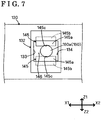
- the fixing mechanism 170 is configured by a pedestal portion 132, a pair of engagement tabs 145 and 145, and a self-taping screw (which will be simply referred to also as "a screw") 160.
- the pedestal portion 132 is provided at the first handle member 130 so as to protrude from an inner wall surface 131 of the first handle member 130 towards the second handle member 140.
- the pair of engagement tabs 145 and 145 is formed to extend from a boss portion 143 of the second handle member 140 towards the pedestal portion 132.
- the fixing mechanism 170 serves as "the fixing mechanism" of the present invention.
- the pedestal portion 132 is formed in a configuration (which will be simply referred to also as "a shape of a box") including an engagement hole 133 formed to open so that the pair of engagement tabs 145 and 145 is engageable with (insertable into) the engagement hole 133, and including a facing space portion (which will be simply referred to also as “an accommodation space portion”) 134 at which a pair of standing walls face each other.
- the facing space portion 134 is for accommodating distal end portions of the pair of engagement tabs 145 and 145 that is in an engaged state (an inserted state) in which the engagement tabs 145 and 145 are engaged with the engagement hole 133.
- the pedestal portion 132 serves as "the pedestal portion" of the present invention.
- the engagement hole 133 of the pedestal portion 132 is a portion which includes a recessed shape and engages with the pair of engagement tabs 145 and 145 arranged at a side of the second handle member 140.
- the engagement hole 133 serves as "the engagement hole" of the present invention.
- the engagement tabs 145 and 145 are arranged as a pair to face each other and to be separated from each other by a predetermined space portion 146 interposed therebetween in the vehicle upper and lower direction Z1, Z2.
- a male threaded portion 160a of the screw 160 is insertable into the space portion 146 that is predetermined.
- the pair of engagement tabs 145 and 145 extends in parallel with the vehicle outer side Y1 from an edge portion of a through hole 144 of the boss portion 143, the through hole 144 which is interposed between the engagement tabs 145 and 145.
- Each of the engagement tabs 145 and 145 includes a tab portion 145b formed at a distal end of an extended portion 145a configured in a flat plate shape.
- a plate thickness of the tab portion 145b is expanded than a plate thickness of the extended portion 145a.
- the pair of engagement tabs 145 and 145 is elastically deformable in a direction in which the engagement tabs 145 and 145 come closer to each other and in a direction in which the engagement tabs 145 and 145 are separated from each other.
- the pair of engagement tabs 145 and 145 serves as "plural engagement tabs" of the present invention.
- the pair of engagement tabs 145 and 145 may be configured to be arranged to face each other in the vehicle front and rear direction X1, X2.
- the number of the engagement tabs 145 provided is not limited to two, and may be increased to more than two, as needed.
- the screw 160 is a known metal screw member where the male threaded portion 160a can form a female threaded portion by a screwing action of the screw 160 for itself even though the female threaded portion is not formed in advance at a target of engagement.
- the screw 160 is inserted into the through hole 144 that is penetratingly formed at the boss portion 143, and is further inserted into the space portion 146 between the engagement tabs 145 and 145 arranged as the pair.
- an inner wall surface of the through hole 144 and a facing wall surface 145c of each engagement tab 145 correspond to portions at which the female threaded portion is formed by the screwing action of the screw 160.
- the self-tapping screw 160 serves as "a screw member” and "a stopper member” of the present invention.
- a metal screw member of various types which includes a male threaded portion that is threadedly engageable with a female threaded portion formed in advance at the target of the engagement may be used.
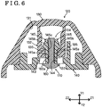
- Figs. 4 to 6 when fixing the first handle member 130 and the second handle member 140 are integrally fixed to each other, first, the pair of engagement tabs 145 and 145 of the second handle member 140 is inserted into the engagement hole 133 formed to open at the pedestal portion 132 of the first handle member 130.
- an engagement protrusion 135 is provided which protrudes such that the tab portion 145b of each engagement tab 145 is engaged at the engagement protrusion 135 (refer to Fig. 6 ).
- the pair of engagement tabs 145 and 145 is pushed by the engagement protrusions 135 and 135 in the course of being inserted into the engagement hole 133, and thus is elastically deformed, from the initial state illustrated in Fig. 3 , in the direction in which the engagement tabs 145 and 145 come closer to each other.
- a temporarily held state is established, in which the pair of engagement tabs 145 and 145 is held relative to the pedestal portion 132 because the tab portions 145b of the respective engagement tabs 145 are engaged at the respective engagement protrusions 135.
- the distal end portions of the pair of engagement tabs 145 and 145 which engages with the engagement hole 133 and thus is in the engaged state, are accommodated in the facing space portion 134 of the pedestal portion 132.
- the screw 160 is screwed into the through hole 144 of the second handle member 140, while being inserted into the through hole 144 of the second handle member 140.
- the male threaded portion 160a of the screw 160 forms the female threaded portion at the inner wall surface of the through hole 144, while coming to threadedly engage with the female threaded portion.
- the male threaded portion 160a thereof forms the female threaded portion at the facing wall surface 145c of each engagement tab 145, while coming to threadedly engage with the female threaded portion.
- the screw 160 is screwed to the facing wall surfaces 145c of the respective engagement tabs 145, and is locked at the pair of engagement tabs 145 and 145.
- the male threaded portion 160a of the screw 160 is arranged at the space portion 146 interposed between the pair of engagement tabs 145 and 145. Accordingly, the pair of engagement tabs 145 and 145 is restricted from elastically deforming in the direction in which the engagement tabs 145 and 145 come closer to each other (that is, a disengaging direction) by the screw 160, and consequently the engagement of the tab portions 145b of the respective engagement tabs 145 and the engagement hole 133 with each other is maintained.
- the male threaded portion 160a of the screw 160 performs a function of restricting the respective engagement tabs 145 engaged with the engagement hole 133 from elastically deforming in the disengaging direction. In consequence, the two handle members 130 and 140 are kept in a fixed state.
- the fixing mechanism 170 As a result of fixing the first handle member 130 and the second handle member 140 to be integral with each other with the use of the fixing mechanism 170, strength similar to a case where a fixing mechanism by fastening of a nut member and a bolt member is used.
- the screw 160 may be prepared in addition to the two handle members 130 and 140.
- the number of parts and components can be reduced compared to a case where a fixing mechanism is employed in which a metal bolt member inserted in an insertion hole of the second handle member 140 is made to threadedly engage with a metal nut member attached to the first handle member 130 by welding and/or insert-molding.
- the screw 160 is screwed in the second handle member 140 arranged at the vehicle inner side. Accordingly, there is no need to screw the screw 160 into the first handle member 130 arranged at the vehicle outer side, the first handle member 130 which is generally formed of resin material (typically, a polycarbonate system resin material (non-crystalline resin)) that is suitable for paintwork and/or plating. As a result, even in a case where the polycarbonate resin material is used in the first handle member 130, the two handle members 130 and 140 are reliably fixed to each other without concern about a problem, including a crack, for example.
- resin material typically, a polycarbonate system resin material (non-crystalline resin)
- a handle 220 of a second embodiment includes a first handle member 230 that is similar to the first handle member 130 and a second handle member 240 that is similar to the second handle member 140.
- the second handle member 240 includes a pair of engagement tabs 245 and 245 which is similar to the pair of engagement tabs 145 and 145.
- the first handle member 230 and the second handle member 240 serve as "the first handle member” and "the second handle member” of the present invention, respectively.
- the handle 220 includes an antenna unit 250 interposed between the first handle member 230 and the second handle member 240, in addition to the first handle member 230 and the second handle member 240.
- the antenna unit 250 includes a known structure and therefore a detailed explanation will be omitted.
- the antenna unit 250 includes a lock sensor electrode 251 and an antenna assy 252.
- the lock sensor electrode 251 is a plate-shaped metal member assembled on the first handle member 230, and performs a function of electromagnetically detecting that a hand of the user is in contact with the first handle member 230 on the basis of a change of electrostatic capacity.
- the lock sensor electrode 251 is connected to an electrode (an antenna assy electrode 252a illustrated in Fig. 13 ) of the antenna assy 252.
- the antenna assy 252 performs a function of electromagnetically detecting an operation of the user for opening the handle 220 on the basis of a change of electrostatic capacity.
- a unit main body 250a, which is made of resin, of the antenna unit 250 includes a through hole 250b formed in a penetrated manner for allowing the pair of engagement tabs 245 and 245 of the second handle member 240 to be inserted in the through hole 250b.
- the first handle member 230 includes a pedestal portion 232 performing a function similar to the pedestal portion 132.
- the pedestal portion 232 serves as "the pedestal portion” of the present invention.
- the pedestal portion 232 is formed in a shape of a box at which an engagement hole 233 is formed to open so that the pair of engagement tabs 245 and 245 of at a side of the second handle member 240 is engageable with (insertable into) the engagement hole 233.
- the pedestal portion 232 serves as "the pedestal portion” of the present invention.
- the engagement hole 233 of the pedestal portion 232 corresponds to a portion having a recessed configuration with which the pair of engagement tabs 245 and 245 engages, and serves as "the engagement hole” of the present invention.
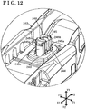
- a curved face 233a is provided at each end portion of the engagement hole 233 in the vehicle front and rear direction X1, X2, a curved face 233a is provided.
- the curved face 233a is formed in a configuration to follow a curved surface (a curved surface 245c in Fig. 12 ) of each engagement tab 245 inserted in the engagement hole 233.
- the curved faces 233a of the engagement hole 233 and the curved surfaces of the respective engagement tabs 245 are in surface contact with each other.
- the second handle member 240 can be positioned relative to the first handle member 230 easily.
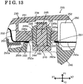
- the pedestal portion 232 includes a pair of standing walls 232a and 232b, and a connection wall 232c.
- the walls 232a and 232b arranged as the pair are portions of the pedestal portion 232, the portions which are formed to be parallel with each other along the vehicle front and rear direction X1, X2 that corresponds to a direction in which the elongated shape of the handle 220 is extended, and are formed to stand towards the second handle member 240.
- connection wall 232c is a portion of the pedestal portion 232, the portion which connects the pair of standing walls 232a and 232b to each other and which includes the engagement hole 233 between the pair of standing walls 232a and 232b.
- the pair of standing walls 232a and 232b, and the connection wall 232c serve as "the pair of standing walls” and "the connection wall” of the present invention, respectively.
- the first handle member 230 including the pedestal portion 232 is formed by resin-molding.
- a protruding portion including, for example, a pin and/or a core is provided at a metal mold for the resin-molding so that a hollow portion including, for example, the engagement hole 233, is formed at the pedestal portion 232 of the first handle member 230
- molten resin flows in a branched manner at the protruding portion at a time of the resin molding.
- the divided flows of the molten resin join together again after being branched, and form a thin line (a weld line WL) at a portion at which the molten resin is fused. It is known that the portion at which the weld line WL is formed is weak in adhesion strength, and thus the pedestal portion 232 is easily cracked.
- a wall thickness d1 of the one standing wall 232a is configured to exceed a wall thickness d2 of the other standing wall 232b.
- a position of the weld line WL can be deviated from an intermediate position of the two standing walls 232a and 232b towards either one of the standing walls in the vehicle upper and lower direction Z1, Z2 by making the wall thickness d1 of the one standing wall 232a and the wall thickness d2 of the other standing wall 232b differ from each other, that is, by making a flow speed of the molten resin flowing at a portion of the metal mold which corresponds to the one standing wall 232a and a flow speed of the molten resin flowing at a portion of the metal mold which corresponds to the other standing wall 232b from each other during the resin-molding.
- the weld line WL is formed at a position (a position close to either one of the standing walls) at which the strength is higher than the intermediate portion, and accordingly the pedestal portion 232 is not easily cracked.
- the second handle member 240 includes the engagement tabs 245 and 245 which functioning similarly to the pair of engagement tabs 145 and 145.
- the engagement tabs 245 and 245 as the pair are arranged to face each other and to be separated from each other in the vehicle front and rear direction X1, X2 by a space portion 246 that is predetermined.
- a shaft portion 260a of a pin 260 made of resin is insertable into the space portion 246.
- a through hole 244 of a boss portion 243 is interposed between the pair of engagement tabs 245 and 245, and the pair of engagement tabs 245 and 245 is extended from an edge portion of the through hole 244 towards the vehicle outer direction Y1 to be parallel with each other.
- Each of the engagement tabs 245 and 245 includes a tab portion 245b formed at a distal end of an extended portion 245a configured in a curved plate shape.
- a plate thickness of the tab portion 245b is expanded than a plate thickness the extended portion 245a.
- the pair of engagement tabs 245 and 245 is elastically deformable in a direction in which the engagement tabs 245 and 245 come closer to each other and in a direction in which the engagement tabs 245 and 245 are separated from each other.
- the pair of engagement tabs 245 and 245 serves as "the plural engagement tabs" of the present invention.
- the pair of engagement tabs 245 and 245 may be configured to be arranged to face each other in the vehicle upper and lower direction Z1, Z2.
- the number of the engagement tabs 245 provided is not limited to two, and may be increased to more than two, as needed.
- the two members corresponding to the first handle member 230 and the second handle member 240, respectively, are integrally fixed to each other with the use of a fixing mechanism 270.
- the fixing mechanism 270 corresponds to "the fixing mechanism" of the present invention.
- the fixing mechanism 270 is configured by the pedestal portion 232 provided at the first handle member 230 in such a manner that the pedestal portion 232 protrudes from an inner wall surface 231 of the first handle member 230 towards the second handle member 240, the pair of engagement tabs 245 and 245 provided to extend from the boss portion 243 of the second handle member 240 towards the pedestal portion 232, and the pin 260 made of resin.
- the antenna unit 250 is assembled on the second handle member 240 in advance in such a manner that the pair of engagement tabs 245 and 245 of the second handle member 240 is inserted into the through hole 250b of the antenna unit 250. Thereafter, the pair of engagement tabs 245 and 245 of the second handle member 240 is inserted into the engagement hole 233 formed to open at the pedestal portion 230 of the first handle member 230. In this case, the tab portions 245b of the respective engagement tabs 245 are engaged at the pedestal portion 232, and accordingly the temporarily held state is established in which the pair of engagement tabs 245 and 245 is held relative to the pedestal portion 232.
- the pin 260 is inserted into the through hole 244 of the second handle member 240 while the pair of engagement tabs 245 and 245 is in the engaged state in which the pair of engagement tabs 245 and 245 is engaged with the engagement hole 233. Further, the pin 260 is inserted into the space portion 246 between the engagement tabs 245 and 245, and therefore the pin 260 is locked at the pair of engagement tabs 245 and 245.
- the pin 260 serves as "a pin” and "the stopper member" of the present invention.
- the shaft portion 260a of the pin 260 is arranged in the space portion 246 interposed between the pair of engagement tabs 245 and 245, and the pair of engagement tabs 245 and 245 is restricted from elastically deforming in the direction in which the engagement tabs 245 and 245 come closer to each other (that is, the disengaging direction) by the pin 260, and consequently the engagement of the respective engagement tabs 245 and the engagement hole 233 with each other is maintained.
- the shaft portion 260a of the pin 260 performs the function of restricting the respective engagement tabs 245 engaged at the engagement hole 233 from elastically deforming in the disengaging direction. In consequence, the two handle members 230 and 240 are kept in the fixed state.
- both the lock sensor electrode 251 and the antenna assy electrode 252a are configured to be sandwiched by the pedestal portion 232 of the first handle member 230 and the boss portion 243 of the second handle member 240 in a state where the lock sensor electrode 251 and the antenna assy electrode 252a are in contact with each other. That is, the lock sensor electrode 251 that is assembled on the first handle member 230 in advance and the antenna assy electrode 252a that is assembled on the second handle member 240 in advance are in contact with each other. Accordingly, a contact point of the lock sensor electrode 251 and the antenna assy electrode 252a is easily assured simply by fixing the two handle members 230 and 240.
- the pin 260 may be prepared in addition to the two handle members 230 and 240.
- the cost of the member itself and/or workload for attaching the member by welding and/or insert-molding do not arise, and accordingly an effect of cost reduction can be obtained.
- the pin 260 made of resin that is relatively inexpensive a component cost of the stopper member can be kept low.
- the explanation is made on the case in which the engagement tabs 145, 245, which are extended from the second handle member 140, 240 at the vehicle inner side towards the first handle member 130, 230 at the vehicle outer side, engage with the pedestal portion 132, 232 of the first handle member 130, 230.
- a structure in which the engagement tabs 145, 245 are provided at the first handle member 130, 230 at the vehicle outer side and the pedestal portion 132, 232 is provide at the second handle member 140, 240 at the vehicle inner side may be applied to the present invention.
- an essential structure of the door handle apparatus 100 including the above-described configuration may be applied to each vehicle door of a vehicle.
- the essential structure of the door handle apparatus 100 may be applied to a vehicle right and left door for a front seat and/or a vehicle right and left door for a rear seat, and further to a vehicle rear door (a back door), for example.
Landscapes
- Engineering & Computer Science (AREA)
- General Engineering & Computer Science (AREA)
- Mechanical Engineering (AREA)
- Lock And Its Accessories (AREA)
Claims (4)
- Türgriffvorrichtung für ein Fahrzeug, wobei die Türgriffvorrichtung umfasst:einen Grundrahmen (110), der konfiguriert ist, um an einer Fahrzeuginnenseite einer Türaußenverkleidung (10) vorgesehen zu sein, die eine Außenfläche einer Fahrzeugtür konfiguriert;einen Außengriff (120; 220), der durch ein erstes Griffelement (130; 230) aus Harz und ein zweites Griffelement (140; 240) aus Harz konfiguriert ist, die durch einen Befestigungsmechanismus (170; 270) einstückig miteinander verbunden sind, wobei sich das zweite Griffelement (140; 240) in Bezug auf das erste Griffelement auf der Fahrzeuginnenseite befindet, wobei der Außengriff (120; 220) konfiguriert ist, von einer Fahrzeugaußenseite der Türaußenverkleidung (10) her am Grundrahmen (110) befestigt zu werden;dadurch gekennzeichnet, dassder Befestigungsmechanismus (170; 270) durch eine Vielzahl von Eingriffslaschen (145; 245), einen Sockelabschnitt (132; 232) und ein Anschlagelement (160; 260) konfiguriert ist;die Vielzahl von Eingriffslaschen (145; 245) an einem Griffelement vorgesehen sind, das eines von dem ersten Griffelement (130; 230) und dem zweiten Griffelement (140; 240) ist, und angeordnet sind, um durch einen vorbestimmten Raumabschnitt (146; 246) voneinander getrennt zu sein und einander gegenüberzustehen;der Sockelabschnitt (132; 232) an dem anderen Griffelement vorgesehen ist, das das andere von dem ersten Griffelement (130; 230) und dem zweiten Griffelement (140; 240) ist, und ein Eingriffsloch (133; 233) aufweist, in das die Vielzahl von Eingriffslaschen (145; 245) einsetzbar sind, unddas Anschlagelement (160; 260) in den Raumabschnitt (146; 246) zwischen der Vielzahl von Eingriffslaschen (145; 245) eingesetzt ist, was ein Zustand ist, in dem es in das Eingriffsloch (133; 233) des Sockelabschnitts (132; 232) eingeführt ist, wobeider Sockelabschnitt (132; 232) ein Paar stehende Wände (232a, 232b), die so ausgebildet sind, dass sie parallel zueinander sind und von dem ersten Griffelement (130; 230) in Richtung auf das zweite Griffelement (140; 240) stehen, und eine Verbindungswand (232c) hat, die das Paar stehende Wände (232a, 232b) miteinander verbindet und das Eingriffsloch (133; 233) zwischen dem Paar stehende Wände hat, unddie Vielzahl von Eingriffslaschen (145; 245), die sich in einem Zustand des Einsetzens in das Eingriffsloch (133; 233) befinden, in einem gegenüberliegenden Raumabschnitt (134; 234) aufgenommen sind, in dem das Paar stehende Wände (232a, 232b) einander gegenüberliegen, wobeieine Schweißlinie (WL), die die Folge des Wiedervereinigens getrennter Ströme geschmolzenen Harzes ist, am Sockelabschnitt (232) ausgebildet ist und ausgebildet ist, um in Richtung auf irgendeine Seite des Paars stehende Wände (232a, 232b) abgelenkt zu werden.
- Türgriffvorrichtung für das Fahrzeug nach Anspruch 1, wobeider Befestigungsmechanismus (170) so konfiguriert ist, dass die Vielzahl von Eingriffslaschen (145) in das Eingriffsloch (133) des am ersten Griffelement (130) vorgesehenen Sockelabschnitts (132) eingreift, wobei die Vielzahl von Eingriffslaschen (145) von dem als das eine Griffelement dienenden zweiten Griffelement (140) in Richtung auf das als das andere Griffelement dienenden ersten Griffelement (130) verlängert ist, unddas Anschlagelement als ein Schraubenelement (160) aus Metall ausgebildet ist, wobei das Schraubenelement in den Raumabschnitt (146) eingesetzt wird, indem es in den Raumabschnitt (146) eingeschraubt wird, der zwischen der Vielzahl von Eingriffslaschen (145) gebildet ist, die sich in einem Zustand befinden, in dem sie in das Eingriffsloch (133) des Sockelabschnitts (132) eingeführt sind.
- Türgriffvorrichtung für das Fahrzeug nach Anspruch 1, wobeider Befestigungsmechanismus (270) so konfiguriert ist, dass die Vielzahl von Eingriffslaschen (245) in das Eingriffsloch (233) des am ersten Griffelement (230) vorgesehenen Sockelabschnitts (232) eingreifen, wobei die Vielzahl von Eingriffslaschen (345) von dem zweiten Griffelement (240), das als das eine Griffelement dient, in Richtung auf das erste Griffelement (230), das als das andere Griffelement dient, verlängert sind, unddas Anschlagelement als ein Stift (260) aus Harz konfiguriert ist, wobei der Stift in den Raumabschnitt (246) eingesetzt wird, der zwischen der Vielzahl von Eingriffslaschen (245) gebildet ist, die sich in einem in das Eingriffsloch (233) des Sockelabschnitts (232) eingesetzten Zustand befinden.
- Türgriffvorrichtung für das Fahrzeug nach Anspruch 3, wobeider Sockelabschnitt (232) so ausgebildet ist, dass er sich entlang einer Harzströmungsrichtung erstreckt, in der geschmolzenes Harz fließt, wenn das Paar stehende Wände (232a, 232b) aus Harz geformt wird, undeine Wanddicke (d1) von einer von dem Paar stehende Wände (232a, 232b) in einer Richtung, die die Harzströmungsrichtung schneidet, und eine Wanddicke (d2) der anderen von dem Paar stehende Wände in einer Richtung, die die Harzströmungsrichtung schneidet, voneinander abweichen.
Applications Claiming Priority (2)
| Application Number | Priority Date | Filing Date | Title |
|---|---|---|---|
| JP2014201013A JP6388121B2 (ja) | 2014-09-30 | 2014-09-30 | 車両用ドアハンドル装置 |
| PCT/JP2015/076864 WO2016052286A1 (ja) | 2014-09-30 | 2015-09-24 | 車両用ドアハンドル装置 |
Publications (3)
| Publication Number | Publication Date |
|---|---|
| EP3203003A1 EP3203003A1 (de) | 2017-08-09 |
| EP3203003A4 EP3203003A4 (de) | 2017-09-13 |
| EP3203003B1 true EP3203003B1 (de) | 2019-01-30 |
Family
ID=55630326
Family Applications (1)
| Application Number | Title | Priority Date | Filing Date |
|---|---|---|---|
| EP15845878.6A Active EP3203003B1 (de) | 2014-09-30 | 2015-09-24 | Griffvorrichtung für eine fahrzeugtür |
Country Status (5)
| Country | Link |
|---|---|
| US (1) | US10280656B2 (de) |
| EP (1) | EP3203003B1 (de) |
| JP (1) | JP6388121B2 (de) |
| CN (1) | CN206844876U (de) |
| WO (1) | WO2016052286A1 (de) |
Families Citing this family (6)
| Publication number | Priority date | Publication date | Assignee | Title |
|---|---|---|---|---|
| JP6064806B2 (ja) * | 2013-06-21 | 2017-01-25 | アイシン精機株式会社 | 車両用のドアハンドル |
| JP6304209B2 (ja) * | 2015-11-30 | 2018-04-04 | アイシン精機株式会社 | 車両用ハンドル装置 |
| JP7207191B2 (ja) * | 2019-06-19 | 2023-01-18 | 株式会社アイシン | 車両用ドアハンドル装置、及び車両用ドアハンドル装置の電子回路装置の固定方法 |
| CN112937400B (zh) * | 2021-03-15 | 2022-08-09 | 重庆长安汽车股份有限公司 | 一种整体式车门立扶手安装结构 |
| JP7577585B2 (ja) * | 2021-03-25 | 2024-11-05 | 株式会社デンソーテン | 組付構造 |
| JP7770117B2 (ja) * | 2021-06-04 | 2025-11-14 | 株式会社アルファ | 車両用ドアハンドル装置 |
Family Cites Families (10)
| Publication number | Priority date | Publication date | Assignee | Title |
|---|---|---|---|---|
| FR2633020B1 (fr) * | 1988-06-21 | 1990-08-10 | Peugeot | Systeme de fixation d'un garnissage et d'un element tel qu'une poignee sur un panneau de carrosserie |
| JP2605319Y2 (ja) * | 1993-03-31 | 2000-07-10 | 株式会社アルファ | ドアハンドル装置 |
| JP4323641B2 (ja) * | 1999-10-22 | 2009-09-02 | 株式会社ニフコ | パーツの取付装置 |
| JP3762227B2 (ja) * | 2001-01-25 | 2006-04-05 | シロキ工業株式会社 | ロック解除用ハンドル機構 |
| CN201130719Y (zh) * | 2007-11-16 | 2008-10-08 | 富士康(昆山)电脑接插件有限公司 | 线缆连接器 |
| JP5162617B2 (ja) | 2010-04-15 | 2013-03-13 | 株式会社ホンダロック | 車両用ドアのアウトハンドル装置 |
| JP5022483B2 (ja) * | 2010-07-26 | 2012-09-12 | アイシン精機株式会社 | 車両用ドアハンドル装置 |
| WO2012151403A1 (en) | 2011-05-04 | 2012-11-08 | Illinois Tool Works Inc. | An assembly for mounting a handle on a vehicle door |
| JP5580263B2 (ja) * | 2011-08-23 | 2014-08-27 | 株式会社ホンダロック | 車両用ドアのアウトハンドル装置 |
| JP2014111980A (ja) * | 2012-11-12 | 2014-06-19 | Kitagawa Kogyo Co Ltd | ネジ |
-
2014
- 2014-09-30 JP JP2014201013A patent/JP6388121B2/ja active Active
-
2015
- 2015-09-24 CN CN201590001021.3U patent/CN206844876U/zh not_active Expired - Lifetime
- 2015-09-24 EP EP15845878.6A patent/EP3203003B1/de active Active
- 2015-09-24 WO PCT/JP2015/076864 patent/WO2016052286A1/ja not_active Ceased
- 2015-09-24 US US15/513,470 patent/US10280656B2/en active Active
Non-Patent Citations (1)
| Title |
|---|
| None * |
Also Published As
| Publication number | Publication date |
|---|---|
| US20170298660A1 (en) | 2017-10-19 |
| EP3203003A1 (de) | 2017-08-09 |
| JP6388121B2 (ja) | 2018-09-12 |
| EP3203003A4 (de) | 2017-09-13 |
| US10280656B2 (en) | 2019-05-07 |
| JP2016069945A (ja) | 2016-05-09 |
| WO2016052286A1 (ja) | 2016-04-07 |
| CN206844876U (zh) | 2018-01-05 |
Similar Documents
| Publication | Publication Date | Title |
|---|---|---|
| EP3203003B1 (de) | Griffvorrichtung für eine fahrzeugtür | |
| US11479995B2 (en) | Fastening device for fastening a first component to a second component | |
| CN104421259B (zh) | 弹性可变形对准紧固件和系统 | |
| CN104271964B (zh) | 具有公差补偿的紧固装置以及预组装和组装方法 | |
| US8950782B2 (en) | Mounting device for securing a seat belt buckle | |
| JP2015511295A (ja) | ファスナ保持デバイス | |
| US9499131B2 (en) | Wiper blade adapter device | |
| KR20120092028A (ko) | 텐션 클램프 | |
| CN110869244B (zh) | 紧固装置、具有该紧固装置的系统及具有该系统的车辆 | |
| WO2016039827A1 (en) | Fastener, in particular for fastening vehicle trim panels to a support | |
| US9103702B2 (en) | Fastening device for fastening an assembly in an opening of a wall of a vehicle | |
| US20140125072A1 (en) | Door handle for vehicle | |
| US10457143B2 (en) | Fastening structure and accelerator pedal device using same | |
| CN104684308A (zh) | 塑胶面板 | |
| TWI458420B (zh) | 易於拆裝之門蓋結構 | |
| CN105829834A (zh) | 将功能性的测量或检测元件固定在车辆车身部件上的固定系统 | |
| US8927889B2 (en) | Electric switch | |
| US9377041B2 (en) | Connecting device | |
| JP7034701B2 (ja) | 車両用部品 | |
| JP2010018208A (ja) | ドアパネル取付用クリップ座を備えるドアトリム基材 | |
| CN102330729B (zh) | 内置于衬套中的螺钉结构和传感器壳体 | |
| CN224003029U (zh) | 一种双向间隔的压铆螺母 | |
| KR20160109950A (ko) | 미닫이문의 손잡이 조립체 | |
| US20140356052A1 (en) | Hot melt assembly structure and assembly method thereof | |
| JP2007262885A (ja) | 中空形材の取付構造及び取付方法 |
Legal Events
| Date | Code | Title | Description |
|---|---|---|---|
| STAA | Information on the status of an ep patent application or granted ep patent |
Free format text: STATUS: THE INTERNATIONAL PUBLICATION HAS BEEN MADE |
|
| PUAI | Public reference made under article 153(3) epc to a published international application that has entered the european phase |
Free format text: ORIGINAL CODE: 0009012 |
|
| STAA | Information on the status of an ep patent application or granted ep patent |
Free format text: STATUS: REQUEST FOR EXAMINATION WAS MADE |
|
| 17P | Request for examination filed |
Effective date: 20170215 |
|
| AK | Designated contracting states |
Kind code of ref document: A1 Designated state(s): AL AT BE BG CH CY CZ DE DK EE ES FI FR GB GR HR HU IE IS IT LI LT LU LV MC MK MT NL NO PL PT RO RS SE SI SK SM TR |
|
| AX | Request for extension of the european patent |
Extension state: BA ME |
|
| A4 | Supplementary search report drawn up and despatched |
Effective date: 20170817 |
|
| RIC1 | Information provided on ipc code assigned before grant |
Ipc: B60J 5/04 20060101ALI20170810BHEP Ipc: E05B 79/06 20140101ALI20170810BHEP Ipc: E05B 85/16 20140101AFI20170810BHEP |
|
| DAV | Request for validation of the european patent (deleted) | ||
| DAX | Request for extension of the european patent (deleted) | ||
| GRAP | Despatch of communication of intention to grant a patent |
Free format text: ORIGINAL CODE: EPIDOSNIGR1 |
|
| STAA | Information on the status of an ep patent application or granted ep patent |
Free format text: STATUS: GRANT OF PATENT IS INTENDED |
|
| INTG | Intention to grant announced |
Effective date: 20180815 |
|
| GRAS | Grant fee paid |
Free format text: ORIGINAL CODE: EPIDOSNIGR3 |
|
| GRAA | (expected) grant |
Free format text: ORIGINAL CODE: 0009210 |
|
| STAA | Information on the status of an ep patent application or granted ep patent |
Free format text: STATUS: THE PATENT HAS BEEN GRANTED |
|
| AK | Designated contracting states |
Kind code of ref document: B1 Designated state(s): AL AT BE BG CH CY CZ DE DK EE ES FI FR GB GR HR HU IE IS IT LI LT LU LV MC MK MT NL NO PL PT RO RS SE SI SK SM TR |
|
| REG | Reference to a national code |
Ref country code: GB Ref legal event code: FG4D |
|
| REG | Reference to a national code |
Ref country code: CH Ref legal event code: EP |
|
| REG | Reference to a national code |
Ref country code: AT Ref legal event code: REF Ref document number: 1093405 Country of ref document: AT Kind code of ref document: T Effective date: 20190215 |
|
| REG | Reference to a national code |
Ref country code: IE Ref legal event code: FG4D |
|
| REG | Reference to a national code |
Ref country code: DE Ref legal event code: R096 Ref document number: 602015024213 Country of ref document: DE |
|
| REG | Reference to a national code |
Ref country code: LT Ref legal event code: MG4D |
|
| REG | Reference to a national code |
Ref country code: NL Ref legal event code: MP Effective date: 20190130 |
|
| PG25 | Lapsed in a contracting state [announced via postgrant information from national office to epo] |
Ref country code: NL Free format text: LAPSE BECAUSE OF FAILURE TO SUBMIT A TRANSLATION OF THE DESCRIPTION OR TO PAY THE FEE WITHIN THE PRESCRIBED TIME-LIMIT Effective date: 20190130 Ref country code: PL Free format text: LAPSE BECAUSE OF FAILURE TO SUBMIT A TRANSLATION OF THE DESCRIPTION OR TO PAY THE FEE WITHIN THE PRESCRIBED TIME-LIMIT Effective date: 20190130 Ref country code: SE Free format text: LAPSE BECAUSE OF FAILURE TO SUBMIT A TRANSLATION OF THE DESCRIPTION OR TO PAY THE FEE WITHIN THE PRESCRIBED TIME-LIMIT Effective date: 20190130 Ref country code: ES Free format text: LAPSE BECAUSE OF FAILURE TO SUBMIT A TRANSLATION OF THE DESCRIPTION OR TO PAY THE FEE WITHIN THE PRESCRIBED TIME-LIMIT Effective date: 20190130 Ref country code: LT Free format text: LAPSE BECAUSE OF FAILURE TO SUBMIT A TRANSLATION OF THE DESCRIPTION OR TO PAY THE FEE WITHIN THE PRESCRIBED TIME-LIMIT Effective date: 20190130 Ref country code: FI Free format text: LAPSE BECAUSE OF FAILURE TO SUBMIT A TRANSLATION OF THE DESCRIPTION OR TO PAY THE FEE WITHIN THE PRESCRIBED TIME-LIMIT Effective date: 20190130 Ref country code: NO Free format text: LAPSE BECAUSE OF FAILURE TO SUBMIT A TRANSLATION OF THE DESCRIPTION OR TO PAY THE FEE WITHIN THE PRESCRIBED TIME-LIMIT Effective date: 20190430 Ref country code: PT Free format text: LAPSE BECAUSE OF FAILURE TO SUBMIT A TRANSLATION OF THE DESCRIPTION OR TO PAY THE FEE WITHIN THE PRESCRIBED TIME-LIMIT Effective date: 20190530 |
|
| REG | Reference to a national code |
Ref country code: AT Ref legal event code: MK05 Ref document number: 1093405 Country of ref document: AT Kind code of ref document: T Effective date: 20190130 |
|
| PG25 | Lapsed in a contracting state [announced via postgrant information from national office to epo] |
Ref country code: IS Free format text: LAPSE BECAUSE OF FAILURE TO SUBMIT A TRANSLATION OF THE DESCRIPTION OR TO PAY THE FEE WITHIN THE PRESCRIBED TIME-LIMIT Effective date: 20190530 Ref country code: RS Free format text: LAPSE BECAUSE OF FAILURE TO SUBMIT A TRANSLATION OF THE DESCRIPTION OR TO PAY THE FEE WITHIN THE PRESCRIBED TIME-LIMIT Effective date: 20190130 Ref country code: BG Free format text: LAPSE BECAUSE OF FAILURE TO SUBMIT A TRANSLATION OF THE DESCRIPTION OR TO PAY THE FEE WITHIN THE PRESCRIBED TIME-LIMIT Effective date: 20190430 Ref country code: HR Free format text: LAPSE BECAUSE OF FAILURE TO SUBMIT A TRANSLATION OF THE DESCRIPTION OR TO PAY THE FEE WITHIN THE PRESCRIBED TIME-LIMIT Effective date: 20190130 Ref country code: LV Free format text: LAPSE BECAUSE OF FAILURE TO SUBMIT A TRANSLATION OF THE DESCRIPTION OR TO PAY THE FEE WITHIN THE PRESCRIBED TIME-LIMIT Effective date: 20190130 Ref country code: GR Free format text: LAPSE BECAUSE OF FAILURE TO SUBMIT A TRANSLATION OF THE DESCRIPTION OR TO PAY THE FEE WITHIN THE PRESCRIBED TIME-LIMIT Effective date: 20190501 |
|
| PG25 | Lapsed in a contracting state [announced via postgrant information from national office to epo] |
Ref country code: AL Free format text: LAPSE BECAUSE OF FAILURE TO SUBMIT A TRANSLATION OF THE DESCRIPTION OR TO PAY THE FEE WITHIN THE PRESCRIBED TIME-LIMIT Effective date: 20190130 Ref country code: SK Free format text: LAPSE BECAUSE OF FAILURE TO SUBMIT A TRANSLATION OF THE DESCRIPTION OR TO PAY THE FEE WITHIN THE PRESCRIBED TIME-LIMIT Effective date: 20190130 Ref country code: EE Free format text: LAPSE BECAUSE OF FAILURE TO SUBMIT A TRANSLATION OF THE DESCRIPTION OR TO PAY THE FEE WITHIN THE PRESCRIBED TIME-LIMIT Effective date: 20190130 Ref country code: DK Free format text: LAPSE BECAUSE OF FAILURE TO SUBMIT A TRANSLATION OF THE DESCRIPTION OR TO PAY THE FEE WITHIN THE PRESCRIBED TIME-LIMIT Effective date: 20190130 Ref country code: RO Free format text: LAPSE BECAUSE OF FAILURE TO SUBMIT A TRANSLATION OF THE DESCRIPTION OR TO PAY THE FEE WITHIN THE PRESCRIBED TIME-LIMIT Effective date: 20190130 Ref country code: IT Free format text: LAPSE BECAUSE OF FAILURE TO SUBMIT A TRANSLATION OF THE DESCRIPTION OR TO PAY THE FEE WITHIN THE PRESCRIBED TIME-LIMIT Effective date: 20190130 Ref country code: CZ Free format text: LAPSE BECAUSE OF FAILURE TO SUBMIT A TRANSLATION OF THE DESCRIPTION OR TO PAY THE FEE WITHIN THE PRESCRIBED TIME-LIMIT Effective date: 20190130 |
|
| REG | Reference to a national code |
Ref country code: DE Ref legal event code: R097 Ref document number: 602015024213 Country of ref document: DE |
|
| PG25 | Lapsed in a contracting state [announced via postgrant information from national office to epo] |
Ref country code: SM Free format text: LAPSE BECAUSE OF FAILURE TO SUBMIT A TRANSLATION OF THE DESCRIPTION OR TO PAY THE FEE WITHIN THE PRESCRIBED TIME-LIMIT Effective date: 20190130 |
|
| PLBE | No opposition filed within time limit |
Free format text: ORIGINAL CODE: 0009261 |
|
| STAA | Information on the status of an ep patent application or granted ep patent |
Free format text: STATUS: NO OPPOSITION FILED WITHIN TIME LIMIT |
|
| PG25 | Lapsed in a contracting state [announced via postgrant information from national office to epo] |
Ref country code: AT Free format text: LAPSE BECAUSE OF FAILURE TO SUBMIT A TRANSLATION OF THE DESCRIPTION OR TO PAY THE FEE WITHIN THE PRESCRIBED TIME-LIMIT Effective date: 20190130 |
|
| 26N | No opposition filed |
Effective date: 20191031 |
|
| PG25 | Lapsed in a contracting state [announced via postgrant information from national office to epo] |
Ref country code: SI Free format text: LAPSE BECAUSE OF FAILURE TO SUBMIT A TRANSLATION OF THE DESCRIPTION OR TO PAY THE FEE WITHIN THE PRESCRIBED TIME-LIMIT Effective date: 20190130 |
|
| PG25 | Lapsed in a contracting state [announced via postgrant information from national office to epo] |
Ref country code: TR Free format text: LAPSE BECAUSE OF FAILURE TO SUBMIT A TRANSLATION OF THE DESCRIPTION OR TO PAY THE FEE WITHIN THE PRESCRIBED TIME-LIMIT Effective date: 20190130 |
|
| PG25 | Lapsed in a contracting state [announced via postgrant information from national office to epo] |
Ref country code: MC Free format text: LAPSE BECAUSE OF FAILURE TO SUBMIT A TRANSLATION OF THE DESCRIPTION OR TO PAY THE FEE WITHIN THE PRESCRIBED TIME-LIMIT Effective date: 20190130 |
|
| REG | Reference to a national code |
Ref country code: CH Ref legal event code: PL |
|
| PG25 | Lapsed in a contracting state [announced via postgrant information from national office to epo] |
Ref country code: IE Free format text: LAPSE BECAUSE OF NON-PAYMENT OF DUE FEES Effective date: 20190924 Ref country code: LI Free format text: LAPSE BECAUSE OF NON-PAYMENT OF DUE FEES Effective date: 20190930 Ref country code: CH Free format text: LAPSE BECAUSE OF NON-PAYMENT OF DUE FEES Effective date: 20190930 Ref country code: LU Free format text: LAPSE BECAUSE OF NON-PAYMENT OF DUE FEES Effective date: 20190924 |
|
| REG | Reference to a national code |
Ref country code: BE Ref legal event code: MM Effective date: 20190930 |
|
| PG25 | Lapsed in a contracting state [announced via postgrant information from national office to epo] |
Ref country code: BE Free format text: LAPSE BECAUSE OF NON-PAYMENT OF DUE FEES Effective date: 20190930 |
|
| GBPC | Gb: european patent ceased through non-payment of renewal fee |
Effective date: 20190924 |
|
| PG25 | Lapsed in a contracting state [announced via postgrant information from national office to epo] |
Ref country code: GB Free format text: LAPSE BECAUSE OF NON-PAYMENT OF DUE FEES Effective date: 20190924 |
|
| PG25 | Lapsed in a contracting state [announced via postgrant information from national office to epo] |
Ref country code: CY Free format text: LAPSE BECAUSE OF FAILURE TO SUBMIT A TRANSLATION OF THE DESCRIPTION OR TO PAY THE FEE WITHIN THE PRESCRIBED TIME-LIMIT Effective date: 20190130 |
|
| PG25 | Lapsed in a contracting state [announced via postgrant information from national office to epo] |
Ref country code: HU Free format text: LAPSE BECAUSE OF FAILURE TO SUBMIT A TRANSLATION OF THE DESCRIPTION OR TO PAY THE FEE WITHIN THE PRESCRIBED TIME-LIMIT; INVALID AB INITIO Effective date: 20150924 Ref country code: MT Free format text: LAPSE BECAUSE OF FAILURE TO SUBMIT A TRANSLATION OF THE DESCRIPTION OR TO PAY THE FEE WITHIN THE PRESCRIBED TIME-LIMIT Effective date: 20190130 |
|
| PG25 | Lapsed in a contracting state [announced via postgrant information from national office to epo] |
Ref country code: MK Free format text: LAPSE BECAUSE OF FAILURE TO SUBMIT A TRANSLATION OF THE DESCRIPTION OR TO PAY THE FEE WITHIN THE PRESCRIBED TIME-LIMIT Effective date: 20190130 |
|
| PGFP | Annual fee paid to national office [announced via postgrant information from national office to epo] |
Ref country code: FR Payment date: 20220808 Year of fee payment: 8 |
|
| PG25 | Lapsed in a contracting state [announced via postgrant information from national office to epo] |
Ref country code: FR Free format text: LAPSE BECAUSE OF NON-PAYMENT OF DUE FEES Effective date: 20230930 |
|
| PGFP | Annual fee paid to national office [announced via postgrant information from national office to epo] |
Ref country code: DE Payment date: 20250730 Year of fee payment: 11 |