EP3202344B1 - Dispositif chirurgical endoscopique - Google Patents
Dispositif chirurgical endoscopique Download PDFInfo
- Publication number
- EP3202344B1 EP3202344B1 EP15846589.8A EP15846589A EP3202344B1 EP 3202344 B1 EP3202344 B1 EP 3202344B1 EP 15846589 A EP15846589 A EP 15846589A EP 3202344 B1 EP3202344 B1 EP 3202344B1
- Authority
- EP
- European Patent Office
- Prior art keywords
- endoscope
- outer tube
- treatment tool
- distal end
- base end
- Prior art date
- Legal status (The legal status is an assumption and is not a legal conclusion. Google has not performed a legal analysis and makes no representation as to the accuracy of the status listed.)
- Active
Links
- 238000003780 insertion Methods 0.000 claims description 265
- 230000037431 insertion Effects 0.000 claims description 265
- 230000033001 locomotion Effects 0.000 claims description 87
- 238000010168 coupling process Methods 0.000 claims description 23
- 238000005859 coupling reaction Methods 0.000 claims description 23
- 230000002093 peripheral effect Effects 0.000 claims description 22
- 239000003550 marker Substances 0.000 claims description 5
- 230000000007 visual effect Effects 0.000 description 9
- 238000005286 illumination Methods 0.000 description 8
- 230000008878 coupling Effects 0.000 description 5
- 238000002674 endoscopic surgery Methods 0.000 description 4
- 239000011347 resin Substances 0.000 description 4
- 229920005989 resin Polymers 0.000 description 4
- 238000006073 displacement reaction Methods 0.000 description 3
- 239000013013 elastic material Substances 0.000 description 3
- 229920001971 elastomer Polymers 0.000 description 3
- 239000000463 material Substances 0.000 description 3
- 229910052751 metal Inorganic materials 0.000 description 3
- 239000002184 metal Substances 0.000 description 3
- 150000002739 metals Chemical class 0.000 description 3
- 238000000034 method Methods 0.000 description 3
- 239000007787 solid Substances 0.000 description 3
- 208000005646 Pneumoperitoneum Diseases 0.000 description 2
- 239000000470 constituent Substances 0.000 description 2
- 238000010586 diagram Methods 0.000 description 2
- 230000000694 effects Effects 0.000 description 2
- 230000009545 invasion Effects 0.000 description 2
- 238000001356 surgical procedure Methods 0.000 description 2
- 230000000295 complement effect Effects 0.000 description 1
- 230000000994 depressogenic effect Effects 0.000 description 1
- 238000002350 laparotomy Methods 0.000 description 1
- 229910044991 metal oxide Inorganic materials 0.000 description 1
- 150000004706 metal oxides Chemical class 0.000 description 1
- 230000003287 optical effect Effects 0.000 description 1
- 229920000915 polyvinyl chloride Polymers 0.000 description 1
- 239000004800 polyvinyl chloride Substances 0.000 description 1
- 230000002035 prolonged effect Effects 0.000 description 1
- 239000000523 sample Substances 0.000 description 1
- 239000004065 semiconductor Substances 0.000 description 1
- 229920002379 silicone rubber Polymers 0.000 description 1
- 239000004945 silicone rubber Substances 0.000 description 1
Images


Classifications
-
- A—HUMAN NECESSITIES
- A61—MEDICAL OR VETERINARY SCIENCE; HYGIENE
- A61B—DIAGNOSIS; SURGERY; IDENTIFICATION
- A61B1/00—Instruments for performing medical examinations of the interior of cavities or tubes of the body by visual or photographical inspection, e.g. endoscopes; Illuminating arrangements therefor
- A61B1/00131—Accessories for endoscopes
- A61B1/00135—Oversleeves mounted on the endoscope prior to insertion
-
- A—HUMAN NECESSITIES
- A61—MEDICAL OR VETERINARY SCIENCE; HYGIENE
- A61B—DIAGNOSIS; SURGERY; IDENTIFICATION
- A61B1/00—Instruments for performing medical examinations of the interior of cavities or tubes of the body by visual or photographical inspection, e.g. endoscopes; Illuminating arrangements therefor
- A61B1/00112—Connection or coupling means
- A61B1/00121—Connectors, fasteners and adapters, e.g. on the endoscope handle
- A61B1/00128—Connectors, fasteners and adapters, e.g. on the endoscope handle mechanical, e.g. for tubes or pipes
-
- A—HUMAN NECESSITIES
- A61—MEDICAL OR VETERINARY SCIENCE; HYGIENE
- A61B—DIAGNOSIS; SURGERY; IDENTIFICATION
- A61B1/00—Instruments for performing medical examinations of the interior of cavities or tubes of the body by visual or photographical inspection, e.g. endoscopes; Illuminating arrangements therefor
- A61B1/00147—Holding or positioning arrangements
- A61B1/00154—Holding or positioning arrangements using guiding arrangements for insertion
-
- A—HUMAN NECESSITIES
- A61—MEDICAL OR VETERINARY SCIENCE; HYGIENE
- A61B—DIAGNOSIS; SURGERY; IDENTIFICATION
- A61B1/00—Instruments for performing medical examinations of the interior of cavities or tubes of the body by visual or photographical inspection, e.g. endoscopes; Illuminating arrangements therefor
- A61B1/005—Flexible endoscopes
- A61B1/0051—Flexible endoscopes with controlled bending of insertion part
- A61B1/0052—Constructional details of control elements, e.g. handles
-
- A—HUMAN NECESSITIES
- A61—MEDICAL OR VETERINARY SCIENCE; HYGIENE
- A61B—DIAGNOSIS; SURGERY; IDENTIFICATION
- A61B1/00—Instruments for performing medical examinations of the interior of cavities or tubes of the body by visual or photographical inspection, e.g. endoscopes; Illuminating arrangements therefor
- A61B1/012—Instruments for performing medical examinations of the interior of cavities or tubes of the body by visual or photographical inspection, e.g. endoscopes; Illuminating arrangements therefor characterised by internal passages or accessories therefor
- A61B1/018—Instruments for performing medical examinations of the interior of cavities or tubes of the body by visual or photographical inspection, e.g. endoscopes; Illuminating arrangements therefor characterised by internal passages or accessories therefor for receiving instruments
-
- A—HUMAN NECESSITIES
- A61—MEDICAL OR VETERINARY SCIENCE; HYGIENE
- A61B—DIAGNOSIS; SURGERY; IDENTIFICATION
- A61B17/00—Surgical instruments, devices or methods, e.g. tourniquets
- A61B17/00234—Surgical instruments, devices or methods, e.g. tourniquets for minimally invasive surgery
-
- A—HUMAN NECESSITIES
- A61—MEDICAL OR VETERINARY SCIENCE; HYGIENE
- A61B—DIAGNOSIS; SURGERY; IDENTIFICATION
- A61B17/00—Surgical instruments, devices or methods, e.g. tourniquets
- A61B17/34—Trocars; Puncturing needles
-
- A—HUMAN NECESSITIES
- A61—MEDICAL OR VETERINARY SCIENCE; HYGIENE
- A61B—DIAGNOSIS; SURGERY; IDENTIFICATION
- A61B17/00—Surgical instruments, devices or methods, e.g. tourniquets
- A61B17/34—Trocars; Puncturing needles
- A61B17/3415—Trocars; Puncturing needles for introducing tubes or catheters, e.g. gastrostomy tubes, drain catheters
-
- A—HUMAN NECESSITIES
- A61—MEDICAL OR VETERINARY SCIENCE; HYGIENE
- A61B—DIAGNOSIS; SURGERY; IDENTIFICATION
- A61B17/00—Surgical instruments, devices or methods, e.g. tourniquets
- A61B17/34—Trocars; Puncturing needles
- A61B17/3417—Details of tips or shafts, e.g. grooves, expandable, bendable; Multiple coaxial sliding cannulas, e.g. for dilating
- A61B17/3421—Cannulas
-
- A—HUMAN NECESSITIES
- A61—MEDICAL OR VETERINARY SCIENCE; HYGIENE
- A61B—DIAGNOSIS; SURGERY; IDENTIFICATION
- A61B1/00—Instruments for performing medical examinations of the interior of cavities or tubes of the body by visual or photographical inspection, e.g. endoscopes; Illuminating arrangements therefor
- A61B1/00131—Accessories for endoscopes
- A61B1/00133—Drive units for endoscopic tools inserted through or with the endoscope
-
- A—HUMAN NECESSITIES
- A61—MEDICAL OR VETERINARY SCIENCE; HYGIENE
- A61B—DIAGNOSIS; SURGERY; IDENTIFICATION
- A61B1/00—Instruments for performing medical examinations of the interior of cavities or tubes of the body by visual or photographical inspection, e.g. endoscopes; Illuminating arrangements therefor
- A61B1/00163—Optical arrangements
- A61B1/00188—Optical arrangements with focusing or zooming features
-
- A—HUMAN NECESSITIES
- A61—MEDICAL OR VETERINARY SCIENCE; HYGIENE
- A61B—DIAGNOSIS; SURGERY; IDENTIFICATION
- A61B1/00—Instruments for performing medical examinations of the interior of cavities or tubes of the body by visual or photographical inspection, e.g. endoscopes; Illuminating arrangements therefor
- A61B1/04—Instruments for performing medical examinations of the interior of cavities or tubes of the body by visual or photographical inspection, e.g. endoscopes; Illuminating arrangements therefor combined with photographic or television appliances
- A61B1/05—Instruments for performing medical examinations of the interior of cavities or tubes of the body by visual or photographical inspection, e.g. endoscopes; Illuminating arrangements therefor combined with photographic or television appliances characterised by the image sensor, e.g. camera, being in the distal end portion
-
- A—HUMAN NECESSITIES
- A61—MEDICAL OR VETERINARY SCIENCE; HYGIENE
- A61B—DIAGNOSIS; SURGERY; IDENTIFICATION
- A61B1/00—Instruments for performing medical examinations of the interior of cavities or tubes of the body by visual or photographical inspection, e.g. endoscopes; Illuminating arrangements therefor
- A61B1/06—Instruments for performing medical examinations of the interior of cavities or tubes of the body by visual or photographical inspection, e.g. endoscopes; Illuminating arrangements therefor with illuminating arrangements
- A61B1/0661—Endoscope light sources
- A61B1/0669—Endoscope light sources at proximal end of an endoscope
-
- A—HUMAN NECESSITIES
- A61—MEDICAL OR VETERINARY SCIENCE; HYGIENE
- A61B—DIAGNOSIS; SURGERY; IDENTIFICATION
- A61B1/00—Instruments for performing medical examinations of the interior of cavities or tubes of the body by visual or photographical inspection, e.g. endoscopes; Illuminating arrangements therefor
- A61B1/06—Instruments for performing medical examinations of the interior of cavities or tubes of the body by visual or photographical inspection, e.g. endoscopes; Illuminating arrangements therefor with illuminating arrangements
- A61B1/07—Instruments for performing medical examinations of the interior of cavities or tubes of the body by visual or photographical inspection, e.g. endoscopes; Illuminating arrangements therefor with illuminating arrangements using light-conductive means, e.g. optical fibres
-
- A—HUMAN NECESSITIES
- A61—MEDICAL OR VETERINARY SCIENCE; HYGIENE
- A61B—DIAGNOSIS; SURGERY; IDENTIFICATION
- A61B1/00—Instruments for performing medical examinations of the interior of cavities or tubes of the body by visual or photographical inspection, e.g. endoscopes; Illuminating arrangements therefor
- A61B1/313—Instruments for performing medical examinations of the interior of cavities or tubes of the body by visual or photographical inspection, e.g. endoscopes; Illuminating arrangements therefor for introducing through surgical openings, e.g. laparoscopes
- A61B1/3132—Instruments for performing medical examinations of the interior of cavities or tubes of the body by visual or photographical inspection, e.g. endoscopes; Illuminating arrangements therefor for introducing through surgical openings, e.g. laparoscopes for laparoscopy
-
- A—HUMAN NECESSITIES
- A61—MEDICAL OR VETERINARY SCIENCE; HYGIENE
- A61B—DIAGNOSIS; SURGERY; IDENTIFICATION
- A61B17/00—Surgical instruments, devices or methods, e.g. tourniquets
- A61B17/00234—Surgical instruments, devices or methods, e.g. tourniquets for minimally invasive surgery
- A61B2017/00292—Surgical instruments, devices or methods, e.g. tourniquets for minimally invasive surgery mounted on or guided by flexible, e.g. catheter-like, means
- A61B2017/00296—Surgical instruments, devices or methods, e.g. tourniquets for minimally invasive surgery mounted on or guided by flexible, e.g. catheter-like, means mounted on an endoscope
-
- A—HUMAN NECESSITIES
- A61—MEDICAL OR VETERINARY SCIENCE; HYGIENE
- A61B—DIAGNOSIS; SURGERY; IDENTIFICATION
- A61B17/00—Surgical instruments, devices or methods, e.g. tourniquets
- A61B2017/0042—Surgical instruments, devices or methods, e.g. tourniquets with special provisions for gripping
- A61B2017/00438—Surgical instruments, devices or methods, e.g. tourniquets with special provisions for gripping connectable to a finger
-
- A—HUMAN NECESSITIES
- A61—MEDICAL OR VETERINARY SCIENCE; HYGIENE
- A61B—DIAGNOSIS; SURGERY; IDENTIFICATION
- A61B17/00—Surgical instruments, devices or methods, e.g. tourniquets
- A61B17/34—Trocars; Puncturing needles
- A61B17/3417—Details of tips or shafts, e.g. grooves, expandable, bendable; Multiple coaxial sliding cannulas, e.g. for dilating
- A61B17/3421—Cannulas
- A61B2017/3445—Cannulas used as instrument channel for multiple instruments
Definitions
- the present invention relates to a surgical apparatus for an endoscope, and particularly, relates to a surgical apparatus for an endoscope that can operate an endoscope and a treatment tool inserted through two insertion passages provided in an outer tube in an interlocking manner.
- endoscopic surgery using endoscopes is widely performed.
- endoscopes hard endoscopes
- a treatment tool is inserted into the body cavity from another hole.
- treatment of a living body tissue is performed with the treatment tool while observing the living body tissue within the body cavity with the endoscope.
- one or a plurality of treatment tools are used simultaneously with the endoscope. Therefore, since it is difficult for one operator to simultaneously operate the endoscope and the plurality of treatment tools, for example, a task where the operator operates treatment tools using both hands while making an assistant called an endoscopic technician operate the endoscope is normally performed.
- the applicant of the present application suggests a technique in which an endoscope and a treatment tool are combined together by an outer tube, and if the treatment tool is moved forward and backward, the endoscope is also moved forward and backward in an interlocking manner with this movement of the treatment tool (refer to WO2013/176167A ).
- the outer tube that guides an insertion part of the endoscope and an insertion part of the treatment tool into a body cavity includes a tubular outer tube body that is inserted in a state where the insertion part of the endoscope and the insertion part of the treatment tool are made to be parallel to each other.
- An interlocking member that is movable forward and backward in an axial direction and has an endoscope coupling part and a treatment tool-coupling part is provided inside the outer tube body.
- the insertion part of the endoscope and the insertion part of the treatment tool are held by the respective coupling parts of the interlocking member in a state where the insertion parts are made to be parallel to each other. If the insertion part of the treatment tool is moved in the axial direction, the insertion part of the endoscope also moves in the axial direction in an interlocking manner with this movement.
- WO 2013/176167 A1 discloses a surgical apparatus having an endoscope, a treatment tool, an outer tube, an interlocking member and a first and second stopper as defined by the preamble of claim 1.
- JP 2004 180858 A discloses a surgical apparatus in which an outer tube and an endoscope have a specific first length and second length, respectively.
- mounting work of the endoscope onto the outer tube may be completed in a state where the endoscope-coupling part is coupled to a position that is excessively close to a distal end side of the insertion part of the endoscope.
- the endoscope and the treatment tool are interlocked with each other by the interlocking member and move to a base end side, a situation where the distal end of the insertion part of the endoscope enters the inside of the outer tube may occur.
- the invention has been made in view of such circumstances, and an object thereof is to provide a surgical apparatus for an endoscope that can appropriately and easily perform mounting work of an endoscope onto an outer tube.
- a surgical apparatus for an endoscope is a surgical apparatus for an endoscope comprising an endoscope having an observation window at a distal end thereof; a treatment tool having a treatment part at a distal end thereof; and an outer tube that passes through a body wall, is inserted into a body cavity, and guides the endoscope and the treatment tool into the body cavity.
- the outer tube includes an outer tube body having a distal end, a base end, and a longitudinal axis, a first distal end opening and a second distal end opening provided at the distal end of the outer tube body, a first base end opening and a second base end opening provided at the base end of the outer tube body, an endoscope insertion passage that is provided along the longitudinal axis of the outer tube body, allows the first distal end opening and the first base end opening to communicate with each other therethrough, and allows the endoscope to be inserted therethrough so as to be movable forward and backward, a treatment tool insertion passage that is provided along the longitudinal axis of the outer tube body, allows the second distal end opening and the second base end opening to communicate with each other therethrough, and allows the treatment tool to be inserted therethrough so as to be movable forward and backward, an interlocking member that has an endoscope-coupling part coupled to the endoscope inserted through the endoscope insertion passage, and a treatment tool-coupling part coupled
- the endoscope has a positioning part at a position apart by at least Lt+L1 from a distal end of the endoscope toward a base end side thereof when a movement distance of the interlocking member when the interlocking member moves from a first position where movement thereof to the distal end side of the outer tube body is restricted by the first stopper to a second position where movement thereof to the base end side of the outer tube body is restricted by the second stopper is defined as L1 and a length of the outer tube body in a longitudinal axis direction is defined as Lt.
- the positioning part of the insertion part of the endoscope is matched with the position of the base end of the outer tube.
- the insertion part of the endoscope protrudes by at least the movement distance L1 or more of the interlocking member from the distal end of the outer tube. For that reason, at the time of the treatment after the mounting of the endoscope and the treatment tool onto the outer tube, even in a case where the endoscope and the treatment tool are interlocked with each other by the interlocking member and moved to the second position where the movement of the interlocking member to the base end side is restricted, the distal end of the insertion part of the endoscope does not enter the inside of the outer tube. Hence, the endoscope-coupling part of the interlocking member is in the state of being coupled to the insertion part of the endoscope at a suitable position, and the mounting of the endoscope to the outer tube is appropriately performed.
- the positioning part has an abutment part that abuts against a base end surface of the outer tube body from the base end side.
- the mounting of the endoscope onto the outer tube can be appropriately performed simply by making the abutment part of the endoscope insertion part abut against the base end of the outer tube at the time of the mounting of the endoscope onto the outer tube.
- the abutment part is an operating part gripped by an operator who operates the endoscope.
- the abutment part can also be used for operation, such as the forward and backward movement operation of the endoscope, and it is also possible to make provision of the abutment part and the operating part unnecessary.
- the operating part has a shaft part having a larger external diameter than the internal diameter of the first base end opening.
- the shaft part has an outer peripheral surface in which at least one of an antislip shape or an antislip member is formed.
- the shaft part is made to serve also as the operating part of the endoscope, the operation of the endoscope is easily performed.
- the positioning part is a marker that is formed on a surface of the endoscope and indicates a position apart by at least Lt+L1 from the distal end of the endoscope toward the base end side thereof.
- the positioning part can be simply provided.
- the positioning part is provided at a position apart by Lt+L1 from the distal end of the endoscope toward the base end side thereof.
- this aspect is an aspect in which the amount of protrusion of the insertion part of the endoscope from the distal end of the outer tube becomes the minimum in a case where the insertion part of the endoscope is kept from entering the inside of the outer tube.
- the positioning part is provided at the position apart exactly by Lt+L1 from the distal end of the endoscope to the base end side. Therefore, the amount of protrusion of the endoscope from the distal end of the outer tube can be easily estimated simply by confirming the distance between the positioning part and the base end of the outer tube.
- the interlocking member has a non-sensing region where the forward and backward movement of either the endoscope or the treatment tool does not interlock with the movement of the other and a sensing region where the forward and backward movement of either the endoscope or the treatment tool interlocks with the movement of the other.
- the endoscope since the endoscope does not move forward and backward, for example, with respect to the forward and backward movement operation of the treatment tool in the non-sensing region, there is an advantage that a stable observation image can be obtained.
- the mounting work of the endoscope onto the outer tube can be appropriately and easily performed.
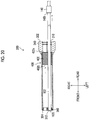
- Fig. 1 is a schematic block diagram of a surgical apparatus for an endoscope according to the invention.
- a surgical apparatus for an endoscope 10 includes an endoscope 100 that observes the inside of a patient's body cavity, a treatment tool 200 for examining or treating a diseased site within the patient's body cavity, an outer tube 300 that is inserted into a body wall and guides the endoscope 100 and the treatment tool 200 into the body cavity, and an exterior tube 500 fitted to the outer tube 300.
- the endoscope 100 is, for example, a hard endoscope, such as a laparoscope, and includes an insertion part 102 (hereinafter referred to as "endoscope insertion part 102") that is inserted into a body cavity, and that has an outer peripheral part surrounded by an elongated hard tubular body, and a cable part 104 that is provided continuously with a base end side of the endoscope insertion part 102 and that has an outer peripheral part surrounded by an elongated flexible tubular body.
- endoscope insertion part 102 an insertion part 102
- cable part 104 that is provided continuously with a base end side of the endoscope insertion part 102 and that has an outer peripheral part surrounded by an elongated flexible tubular body.
- the cable part 104 indicates a flexible cable portion in which a wire rod, such as a cable or a light guide, which extends from a base end of the endoscope insertion part 102, is housed by covering the wire rod with, for example, a flexible insulating member, such as polyvinyl chloride.
- a connector (not illustrated) is provided at an end of the cable part 104 on its extension destination, and each of a processor device 108 and a light source device 110 is detachably connected to the cable part via the connector. Additionally, the processor device 108 is connected to a monitor 112 via a cable.
- a distal end surface 114 of the endoscope insertion part 102 is provided with an observation window 116 and illumination windows 118 and 118.
- the observation window 116 is a constituent element of an observation part of the endoscope 100, and an objective lens of an observation optical system, and a solid image pickup element, such as a charge coupled device (CCD) image sensor or a complementary metal oxide semiconductor (CMOS) image sensor, which is disposed at an image pickup position of the objective lens, are disposed behind the observation window 116.
- a signal cable (not illustrated) connected to this solid image pickup element is inserted through the endoscope insertion part 102 and the cable part 104 of Fig. 1 , is provided to extend up to the connector (not illustrated), and is connected to the processor device 108.
- An observation image picked up from the observation window 116 is formed on a light-receiving surface of the image pickup element, and is converted into electrical signals (image pickup signals), and the electrical signals are output to the processor device 108 via the signal cable and are converted into video signals. Then, the video signals are output to the monitor 112 connected to the processor device 108, and the observation image (endoscopic image) is displayed on a screen of the monitor 112.
- An exit end of the light guide (not illustrated) is disposed behind the illumination windows 118 and 118 of Fig. 2 .
- the light guide is inserted through the endoscope insertion part 102 and the cable part 104 of Fig. 1 and has an incident end disposed within the connector (not illustrated).
- the connector by coupling the connector to the light source device 110, the illumination light radiated from the light source device 110 is transmitted to the illumination windows 118 and 118 via the light guide, and is radiated forward from the illumination windows 118 and 118.
- the two illumination windows 118 and 118 are disposed on the distal end surface 114 of the endoscope insertion part 102.
- the number of illumination windows 118 is not limited, and the number thereof may be one or may be three or more.
- the cable part 104 of the endoscope 100 is provided with a forward and backward movement operating part 130 for hooking the index finger of a right hand gripping an operating part 204 of the treatment tool 200, and performing a forward and backward movement operation of the endoscope 100 in a forward-backward direction of the endoscope 100.
- the forward and backward movement operating part 130 is disposed at a position adjacent to the operating part 204 of the treatment tool 200, and has, for example, three hooking parts 132 of the same configuration.
- Each hooking part 132 is formed in an annular shape (ring shape) using elastic materials (for example, rubber materials), and has an opening of such a size that an index finger can pass therethrough.
- an operator can pass the index finger of his/her right hand gripping the operating part 204 of the treatment tool 200, through any hooking part 132 of the forward and backward movement operating part 130 to perform the forward and backward movement operation of the endoscope 100, and can easily perform the operation of the treatment tool 200 and the forward and backward movement operation of the endoscope 100 only with his/her right hand.
- the endoscope 100 may not include the forward and backward movement operating part 130, and the detailed description of the forward and backward movement operating part 130 will be omitted.
- endoscope insertion part 102 of the endoscope 100 is provided with a larger-diameter part 140, the details thereof will be described below.
- the treatment tool 200 consists of, for example, forceps, and includes an elongated insertion part 202 (hereinafter referred to as a "treatment tool insertion part 202") that is inserted into a body cavity, an operating part 204 that is provided on the base end side of the treatment tool insertion part 202 and is gripped by an operator, and a treatment part 206 that is provided on a distal end side of the treatment tool insertion part 202 and is operable by the operation of the operating part 204.
- a treatment tool insertion part 202 elongated insertion part 202
- an operating part 204 that is provided on the base end side of the treatment tool insertion part 202 and is gripped by an operator
- a treatment part 206 that is provided on a distal end side of the treatment tool insertion part 202 and is operable by the operation of the operating part 204.
- the treatment tool insertion part 202 is provided with a tubular sheath 208, and an operating shaft (not illustrated) that is inserted into the sheath 208 so as to be movable in the direction of an axial center.
- the operating part 204 is provided with a fixed handle 210, and a movable handle 214 that is turnably coupled to the fixed handle 210 via a turning pin.
- a base end part of the operating shaft is coupled to the movable handle 214.
- the treatment part 206 is provided with a pair of gripping members that is openable and closable.
- the gripping members are coupled to a distal end part of the operating shaft via a driving mechanism (not illustrated). With the turning operation of the movable handle 214 of the operating part 204, the gripping members of the treatment part 206 are opened and closed via the operating shaft and the driving mechanism.
- the treatment tool 200 is not limited to the forceps, and may be, for example, other treatment tools, such as a laser probe, a suture device, an electric scalpel, a needle holder, an ultrasonic device, and an aspirator.
- other treatment tools such as a laser probe, a suture device, an electric scalpel, a needle holder, an ultrasonic device, and an aspirator.
- the outer tube 300 allows the endoscope insertion part 102 and the treatment tool insertion part 202, which are inserted thereinto from the base end side, to be inserted therethrough and delivered from the distal end side.
- the outer tube 300 By inserting the outer tube 300 into a body wall and having a base end side thereof disposed outside of the body and a distal end side thereof disposed within the body cavity, the endoscope insertion part 102 and the treatment tool insertion part 202 are guided into the body cavity with one outer tube 300.
- the outer tube 300 includes an interlocking function of moving the endoscope insertion part 102 and the treatment tool insertion part 202 forward and backward in an interlocking manner as will be described below in detail.
- the endoscope insertion part 102 can also be moved forward and backward by the forward and backward movement operation of only the treatment tool insertion part 202, and a suitable observation image can be obtained without performing the forward and backward movement operation of the endoscope insertion part 102.
- the details of the configuration and working of the outer tube 300 will be described below.
- the exterior tube 500 illustrated in Fig. 1 is formed in a tubular shape, and as illustrated in Fig. 3 , is externally fitted (sheathed) to and fixed to an outer peripheral surface of the outer tube 300 (a long tubular outer tube body 320 to be described below).
- an outer peripheral part of the exterior tube 500 is provided with a number of lateral grooves 520 running along in a circumferential direction, and longitudinal grooves 504 running along an axial direction are provided, for example, in four places in the circumferential direction.
- a number of the lateral grooves 520 of the exterior tube 500 restrict the forward and backward movement of the exterior tube 500 with respect to the body wall, and the longitudinal grooves in four places of the exterior tube 500 restrict the rotation of the exterior tube 500 in the circumferential direction (around a reference axis 300a) with respect to the body wall. Hence, unintended rotation or forward and backward movement of the outer tube 300 fixed to the exterior tube 500 with respect to the body wall is prevented.
- the outer tube 300 rotates around the reference axis 300a (around the axis) unintentionally with respect to the body wall or moves forward and backward in the direction (axial direction) of the reference axis 300a when the operation of the treatment tool 200, or the like is performed by inserting the endoscope insertion part 102 and the treatment tool insertion part 202 through the outer tube 300 after the outer tube 300 (long tubular outer tube body 320) is inserted into the body wall, there is a problem that the position of a distal end of the endoscope insertion part 102 may fluctuate and an observation visual field may fluctuate unintentionally.
- the exterior tube 500 prevents such unintended fluctuation of the observation visual field.
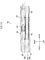
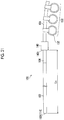
- Fig. 4 is an external perspective view illustrating the outer tube 300.
- the outer tube 300 has an elongated cylindrical shape as a whole, and has an endoscope insertion passage 306 through which the endoscope insertion part 102 of the endoscope 100 is inserted so as to be movable forward and backward, and a treatment tool insertion passage 308 through which the treatment tool insertion part 202 of the treatment tool 200 is inserted so as to be movable forward and backward.
- These insertion passages are parallel to a reference axis 300a indicating a longitudinal axis that is a central axis of the outer tube.
- a central axis of the endoscope insertion passage 306 is referred to as an endoscope insertion axis 306a and a central axis of the treatment tool insertion passage 308 is referred to as a treatment tool insertion axis 308a
- the endoscope insertion axis 306a and the treatment tool insertion axis 308a are parallel to each other, and is also parallel to the reference axis 300a.
- the endoscope insertion axes 306a and the treatment tool insertion axes 308a are equivalent to positions of the central axis of the endoscope insertion part 102 and the central axis of the treatment tool insertion part 202 that are respectively inserted through the endoscope insertion passage 306 and the treatment tool insertion passage 308. Additionally, in the present embodiment, the reference axis 300a, the endoscope insertion axis 306a, and the treatment tool insertion axis 308a are disposed on the same plane. However, a configuration in which the reference axis 300a, the endoscope insertion axis 306a, and the treatment tool insertion axis 308a are disposed on the same plane may not be adopted.
- the base end surface 302 of the outer tube 300 is provided with a first base end opening 310 that is a base end opening that allows the endoscope insertion part 102 to be inserted into the endoscope insertion passage 306 therethrough, and a second base end opening 314 that is base end opening that allows the treatment tool insertion part 202 to be inserted into the treatment tool insertion passage 308 therethrough.
- the distal end surface 304 of the outer tube 300 is provided with a first distal end opening 312 that is a distal end opening that allows the endoscope insertion part 102 inserted into the endoscope insertion passage 306 to be delivered to the outside therethrough, and a second distal end opening 316 that is a distal end opening that allows the treatment tool insertion part 202 inserted into the treatment tool insertion passage 308 to be delivered to the outside therethrough.
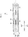
- Fig. 5 is a cross sectional view illustrating the internal structure of the outer tube 300, and illustrates a cross section cut in a plane that includes the reference axis 300a and is orthogonal to an upward-downward direction (cut in a leftward-rightward direction along the reference axis 300a).
- the outer tube 300 has a long tubular outer tube body 320 that occupies substantially the entire area in the forward-backward direction, a base end cap 340 that is attached to a rear end (base end) of the outer tube 300, a distal end cap 360 that is attached to a distal end part, and a slider 400 that is one form of the interlocking member disposed inside the outer tube 300.
- the long tubular outer tube body 320 is formed in an elongated cylindrical shape having the reference axis 300a as a central axis using hard resins, metals, or the like, and has an outer wall 322 that surrounds an outer periphery, and a cavity part 324 that penetrates from a base end of the long tubular outer tube body 320 to a distal end thereof.
- the cavity part 324 includes spaces serving as the endoscope insertion passage 306 and the treatment tool insertion passage 308, and houses the slider 400 and the like.
- the base end cap 340 is formed in a columnar shape of which the diameter is made larger than the external diameter of the long tubular outer tube body 320 using hard resins, metals, or the like, and a rear end surface thereof constitutes the base end surface 302 of the outer tube 300.
- the base end cap 340 is provided with a through-hole 342 and a through-hole 344 that form a portion of the endoscope insertion passage 306 and a portion of the treatment tool insertion passage 308, respectively.
- an opening of the through-hole 342 is equivalent to the above-described first base end opening 310
- an opening of the through-hole 344 is equivalent to the above-described second base end opening 314.
- valve members 346 and 348 are provided with valve members 346 and 348.
- the valve members 346 and 348 for example, open only in a case where the endoscope insertion part 102 and the treatment tool insertion part 202 are inserted therethrough and come into close contact with outer peripheral surfaces (side surfaces) of the endoscope insertion part 102 and the treatment tool insertion part 202 without a substantial gap. This secures the airtightness of spaces closer to the distal end side than the valve members 346 and 348, and reduces the leakage or the like of a pneumoperitoneum gas injected into the body cavity to the outside of the body.
- the distal end cap 360 is formed of hard resins, metals, or the like, and a distal end surface thereof constitutes the distal end surface 304 of the outer tube 300.
- the distal end cap 360 is provided with a through-hole 362 and a through-hole 364 that form a portion of the endoscope insertion passage 306 and a portion of the treatment tool insertion passage 308, respectively.
- an opening of the through-hole 362 is equivalent to the above-described first distal end opening 312, and an opening of the through-hole 364 is equivalent to the second distal end opening 316.
- the long tubular outer tube body 320, the base end cap 340, and the distal end cap 360 show one form of constituent members that constitutes the outer tube body of the outer tube 300, and the outer tube body is not limited to the above configuration.
- the long tubular outer tube body 320 and the base end cap 340 or the long tubular outer tube body 320 and the distal end cap 360 may be integrally formed, or may be integrally formed in their entirety.
- outer tube body may have the following configurations.
- the outer tube body has a distal end, a base end, and a longitudinal axis, and includes a first distal end opening and a second distal end opening equivalent to the above-described first distal end opening 312 and second distal end opening 316 that are provided at the distal end of the outer tube body, and a first base end opening and a second base end opening equivalent to the above-described first base end opening 310 and the second base end opening 314 that are provided at the base end of the outer tube body.
- the outer tube body just has to include an endoscope insertion passage and a treatment tool insertion passage equivalent to the above-described endoscope insertion passage 306 and treatment tool insertion passage 308 that are provided along the longitudinal axis of the outer tube body, that is, the endoscope insertion passage that communicates with the first distal end opening and the first base end opening and allows the endoscope 100 to be inserted therethrough so as to be movable forward and backward, and the treatment tool insertion passage that communicates with the second distal end opening and the second base end opening and allows the treatment tool 200 to be inserted therethrough so as to be movable forward and backward.
- the slider 400 is housed within (the cavity part 324) the long tubular outer tube body 320, and is supported so as to be movable forward and backward in the direction of the reference axis 300a.
- the slider 400 is an interlocking member that is coupled to the endoscope insertion part 102 inserted through the endoscope insertion passage 306 and the treatment tool insertion part 202 inserted through the treatment tool insertion passage 308 and that has a non-sensing region where the forward and backward movement of either the endoscope insertion part or the treatment tool insertion part in the forward-backward direction (axial direction) does not interlock with the movement of the other and a sensing region where the forward and backward movement of either the endoscope insertion part or the treatment tool insertion part interlocks with the movement of the other. That is, the endoscope insertion part 102 is adapted to interlock with the forward and backward movement of the treatment tool insertion part 202 in the axial direction with play by the slider 400.
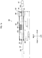
- FIG. 6 is an enlarged cross sectional view illustrating a portion, in which the slider 400 is disposed in Fig. 5 , in an enlarged manner, and illustrates a state where the endoscope insertion part 102 and the treatment tool insertion part 202 are inserted through the endoscope insertion passage 306 and the treatment tool insertion passage 308, respectively.
- FIG. 7 is a cross sectional view as seen from arrow A-A in FIG. 6 .
- Figs. 8 and 9 are respectively perspective views illustrating the slider 400 from the rear upper left and from the rear upper right.
- the slider 400 has a slider body 402 that holds components of the slider 400.
- protruding strips 408 and 410 that extend in the direction (forward-backward direction) of the reference axis 300a are formed on a flat upper surface 404 (refer to Figs. 8 and 9 ) and a flat lower surface 406 of the slider body 402.
- a pair of left and right long plate-shaped guide plates 374 and 374 and a pair of left and right long plate-shaped guide plates 376 and 376 which are laid between the base end cap 340 and the distal end cap 360 and illustrated in Fig. 7 , are respectively supported by an upper part and a lower part within the long tubular outer tube body 320, and guide grooves 370 and 372, which extend in the direction of the reference axis 300a from the base end cap 340 to the distal end cap 360, are formed by a gap between the guide plates 374 and 374 and a gap between the guide plates 376 and 376.
- the protruding strips 408 and 410 of the slider body 402 are respectively fitted into the guide grooves 370 and 372 within the long tubular outer tube body 320, and the upper surface 404 and the lower surface 406 are disposed in a state where these surfaces contacted or approached the guide plates 374 and 374 and the guide plates 376 and 376.
- the slider 400 is supported so as to be movable forward and backward in the forward-backward direction within the long tubular outer tube body 320, and is supported in a state where the movement of the slider in the upward-downward direction and in the leftward-rightward direction and the rotation of the slider in all directions (directions around three axes including a forward-backward axis, a leftward-rightward axis, and an upward-downward direction) are restricted (a state where the rotation of the slider around at least the reference axis 300a is impossible).
- the slider 400 moves forward and backward within a movable range having a position where the slider abuts against the base end cap 340 as a rear end, and having a position where the slider abuts against the distal end cap 360 as a front end.
- the guide grooves 370 and 372 may not be formed by the guide plates 374 and 374 and the guide plates 376 and 376 disposed within the long tubular outer tube body 320, and may be formed in the outer wall 322 of the long tubular outer tube body 320 or may be formed by other configurations.
- the slider 400 as illustrated in Fig. 5 , has a left endoscope-coupling part 420 that is coupled to (engaged with) the endoscope insertion part 102, and a right treatment tool-coupling part 422 that is coupled to (engaged with) the treatment tool insertion part 202.
- the endoscope-coupling part 420 provided on the left side of the slider body 402 secures a space serving as the endoscope insertion passage 306, within the long tubular outer tube body 320. Additionally, the endoscope-coupling part 420, as illustrated in Fig. 6 , includes a through-hole 424 (refer to Figs. 7, 8 , and 9 ) into which the endoscope insertion part 102 is inserted, and a pressure-contact member 426 that is fixed to the through-hole 424 and is brought into pressure contact with the outer peripheral surface (side surface) of the endoscope insertion part 102 inserted through the endoscope insertion passage 306.
- a through-hole 424 (refer to Figs. 7, 8 , and 9 ) into which the endoscope insertion part 102 is inserted
- a pressure-contact member 426 that is fixed to the through-hole 424 and is brought into pressure contact with the outer peripheral surface (side surface) of the endoscope insertion part 102 inserted through the end
- the pressure-contact member 426 is formed in a cylindrical shape using elastic materials, such as elastic rubber, as illustrated in Figs. 7 and 8 , and is fitted into up to a position coaxial with the through-hole 424 of the slider body 402 from an opening 430 formed on a left side surface 431 of the slider body 402 and fixed to the slider body 402, as illustrated in Fig. 8 .
- the endoscope insertion part 102 when the endoscope insertion part 102 has been inserted through the endoscope insertion passage 306, as illustrated in Fig. 6 , the endoscope insertion part 102 is inserted through the through-hole 424, and the pressure-contact member 426 is brought into pressure contact with (engaged with) the outer peripheral surface of the endoscope insertion part 102. Accordingly, the central axis of the endoscope insertion part 102 is disposed coaxially with the endoscope insertion axis 306a.
- the endoscope insertion part 102 and the slider 400 (slider body 402) are coupled to (engaged with) each other in an interlockable manner via the pressure-contact member 426, and the slider 400 (slider body 402) also integrally moves forward and backward in an interlocking manner with the forward and backward movement of the endoscope insertion part 102 in the forward-backward direction (axial direction).
- the coupling herein is based on the elastic force of the pressure-contact member 426, the engagement position (the position of the endoscope insertion part 102 where the slider 400 is engaged) of the endoscope insertion part 102 coupled to the slider 400 (slider body 402) can be arbitrarily adjusted.
- the sleeve 440 as illustrated in Fig. 7 , includes a sleeve body 444 (frame body) formed in a cylindrical shape, and a pressure-contact member 446 fixed to the inside of the sleeve body 444.
- the pressure-contact member 446 is formed in a cylindrical shape using elastic materials, such as elastic rubber.
- the treatment tool insertion part 202 when the treatment tool insertion part 202 has been inserted through the treatment tool insertion passage 308, as illustrated in Fig. 6 , the treatment tool insertion part 202 is inserted through the inside (the through-hole 450 of Fig. 7 ) of the pressure-contact member 446, the pressure-contact member 446 is brought into pressure contact with (engaged with) the outer peripheral surface of the treatment tool insertion part 202. Accordingly, the central axis of the treatment tool insertion part 202 is disposed coaxially with the treatment tool insertion axis 308a.
- the treatment tool insertion part 202 and the sleeve 440 are coupled to each other in an interlockable manner via the pressure-contact member 446, and the sleeve 440 also integrally moves forward and backward in an interlocking manner with the forward and backward movement of the treatment tool insertion part 202 in the forward-backward direction (axial direction).
- the sleeve 440 also rotates with respect to the slider body 402 in an interlocking manner with the rotation of the treatment tool insertion part 202 around the axis thereof.
- the coupling between the treatment tool insertion part 202 and the sleeve 440 herein is based on the elastic force of the pressure-contact member 446, the engagement position (the position of the treatment tool insertion part 202 where the sleeve 440 is engaged) of the treatment tool insertion part 202 coupled to the sleeve 440 can be arbitrarily adjusted.
- the guide part 460 of the treatment tool-coupling part 422 is formed by a space surrounded by a guide surface 462 of the slider body 402 that extends in the direction of the reference axis 300a (treatment tool insertion axis 308a), within the cavity part 324 of the long tubular outer tube body 320, and an inner peripheral surface of the long tubular outer tube body 320.
- the sleeve 440 is housed and disposed in the space of the guide part 460, is supported so as to be movable in the forward-backward direction and rotatable around its axis, and is supported in a state where the movement of the sleeve in the upward-downward direction and in the leftward-rightward direction is restricted.
- the guide part 460 is provided so as to fall within a range from a base end of the slider body 402 to a distal end thereof, and as illustrated in Figs. 6 and 9 , has end edge parts 466 and 468, which are formed to protrude in a direction orthogonal to the guide surface 462 along an end edge of the guide surface 462, respectively, on the base end side and the distal end side of the slider body 402.
- the end edge parts 466 and 468 abut against the end of the sleeve 440 to restrict the movement of the sleeve 440, when the sleeve 440 disposed in the space of the guide part 460 moves forward and backward in the forward-backward direction.
- the sleeve 440 moves forward and backward within a movable range having a position where the sleeve abuts against the end edge part 466 as a rear end, and having a position where the sleeve abuts against the end edge part 468 as a front end.
- the rear end and the front end of the movable range of the sleeve 440 may not be restricted by the end edge part 466 and the end edge part 468.
- the endoscope 100 endoscope insertion part 102
- the treatment tool 200 treatment tool insertion part 202
- the endoscope insertion part 102 and the treatment tool insertion part 202 are mounted on the outer tube 300.
- the endoscope insertion part 102 is coupled to the slider body 402 of the slider 400
- the treatment tool insertion part 202 is coupled to the sleeve 440 of the slider 400.
- the exterior tube 500 is not illustrated in Fig. 13 , and Fig. 14 illustrated therebelow, the exterior tube 500 is fitted to the outer tube 300 as illustrated in Fig. 3 . However, it is also possible to use the outer tube 300 without fitting the exterior tube 500 thereto. Additionally, the forward and backward movement operating part 130 of the endoscope 100 is also omitted in the drawings.
- Supposing the state of (A) part of Fig. 13 is a state where the sleeve 440 reaches neither the front end nor the rear end of the movable range thereof with respect to the slider body 402 (guide part 460) as illustrated in Fig. 10 , and if an operator minutely moves the treatment tool insertion part 202 forward with his/her hand that is gripping the operating part 204 of the treatment tool 200, the slider body 402 does not move with respect to the outer tube 300 (long tubular outer tube body 320), but only the sleeve 440 moves forward with respect to the slider body 402 within the movable range thereof with respect to the slider body 402.
- supposing the state of (A) part of Fig. 13 is a state where the sleeve 440 reaches neither the front end nor the rear end of the movable range thereof with respect to of the slider body 402 (guide part 460) as illustrated in Fig. 10 , and if the operator minutely moves the treatment tool insertion part 202 backward with his/her hand that is gripping the operating part 204 of the treatment tool 200, the slider body 402 does not move with respect to the outer tube 300 (long tubular outer tube body 320), but only the sleeve 440 moves backward with respect to the slider body 402 within the movable range thereof with respect to the slider body 402.
- the endoscope 100 does not move forward and backward with respect to the minute forward and backward movement operation of the treatment tool 200, that is, the forward and backward movement operation thereof in the non-sensing region, the range of an observation image to be displayed on the monitor 112 does not vary, and the size of a target to be observed can be prevented from fluctuating according to minute displacement of the treatment tool 200. Accordingly, a sense of perspective can be suitably maintained, and a stable observation image can be provided.
- a state where the sleeve 440 reaches the front end of the movable range thereof with respect to the slider body 402 as illustrated in Fig. 11 is brought into after the forward movement of the sleeve 440 of the slider 400 in the non-sensing region until it abuts against the front end of the movable range.
- the endoscope insertion part 102 moves forward in an interlocking manner with the treatment tool insertion part 202.
- the endoscope insertion part 102 moves forward in an interlocking manner with the treatment tool insertion part 202 as illustrated in (B) part of Fig. 14 , compared to the state of (A) part of Fig.
- the slider 400 has the sensing region where the endoscope insertion part 102 interlocks with the forward and backward movement of the treatment tool insertion part 202, and the forward movement operation of the treatment tool 200 at this time becomes a forward movement operation of the slider 400 in the sensing region.
- a state where the sleeve 440 reaches the rear end of the movable range thereof with respect to the slider body 402 as illustrated in Fig. 12 is brought into after the backward movement of the sleeve 440 of the slider 400 in the non-sensing region until it abuts against the rear end of the movable range.
- the endoscope insertion part 102 moves backward in an interlocking manner with the treatment tool insertion part 202.
- the endoscope insertion part 102 moves backward in an interlocking manner with the treatment tool insertion part 202. That is, the backward movement operation of the treatment tool 200 at this time becomes a backward movement operation of the slider 400 in the sensing region.
- the endoscope 100 moves forward and backward with respect to a large forward and backward movement operation of the treatment tool 200, that is, the forward and backward movement operation thereof in the sensing region, the range of an observation image to be displayed on the monitor 112 is continuously changed so as to follow the forward and backward movement of the treatment tool 200. Accordingly, since the size of a target to be observed varies according to the operation of the treatment tool 200, the operator can simply obtain a desired image.
- the endoscope insertion part 102 also moves in an interlocking manner forward, backward, up, down, right, and left.
- the visual field, orientation, and the like of the endoscope 100 can be changed as intended by an operator. Additionally, the visual field is always given to pick up an image of the distal end of the treatment tool, and consequently, an image that is optimal for treatment is automatically provided.
- the checking can be performed by moving the treatment tool insertion part 202, and an operator can perform operations as desired.
- an assistant endoscopic technician
- the endoscope 100 apart from the operator can be made unnecessary, and a troublesome condition in which the operator should instruct an assistant about the visual field, orientation, and the like of the endoscope 100 serially can be eliminated.
- the endoscope insertion part 102 does not interlock. Therefore, the size of a target to be observed within an observation image can be prevented from fluctuating unnecessarily, a sense of perspective can be suitably maintained, and a stable observation image can be provided.
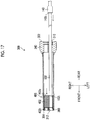
- Fig. 15 is a side view illustrating the endoscope 100 including a positioning part that constitutes a positioning means
- Fig. 16 is a schematic cross sectional view of the outer tube 300 through which the endoscope 100 is inserted.
- Fig. 16 and Figs. 17 to 20 illustrated hereinbelow only the slider body 402 of the slider 400 is illustrated in a simplified manner as a quadrangular block.
- the larger-diameter part 140 is provided on the base end side of the endoscope insertion part 102 of the endoscope 100, as the positioning part that constitutes thee positioning means.
- the endoscope insertion part 102 has a substantially constant diameter in portions other than the larger-diameter part 140, and the larger-diameter part 140 forms a shaft part that has a larger external diameter than the diameter of the portions other than larger-diameter part 140.
- the larger-diameter part 140 is formed, for example, in a columnar shape, and the external diameter thereof is larger than the diameter (internal diameter) of the first base end opening 310 in the base end surface 302 of the outer tube 300.
- the larger-diameter part 140 constitutes an abutment part that is not insertable through the endoscope insertion passage 306 of the outer tube 300.
- the position of the endoscope insertion part 102 capable of being inserted into the endoscope insertion passage 306 of the outer tube 300 is limited to a range up to a position where the distal end 140t of the larger-diameter part 140 abuts against the base end surface 302 of the outer tube 300.
- the maximum insertion length of the outer tube 300 such that the endoscope insertion part 102 can be inserted into the endoscope insertion passage 306 of the outer tube 300 becomes a length Ls from a distal end 102t (distal end surface 114) of the endoscope insertion part 102 to the distal end 140t of the larger-diameter part 140.
- the length (hereinafter simply referred to the length of the outer tube 300) in a direction of a reference axis 300a from the distal end surface 304 of the outer tube 300 to the base end surface 302 is defined as Lt and the length of the movable range of the slider 400 (slider body 402) is defined as L1
- the distal end 140t of the larger-diameter part 140 is provided at a position apart by Lt+L1 from the distal end 102t of the endoscope insertion part 102 toward the base end side, and the length Ls coincides with Lt+L1.
- the movable range of the slider 400 means a movement range from a first position (equivalent to the front end of the above-described movable range) where the movement of the slider 400 (slider body 402) to the distal end side is restricted by a first stopper on the distal end side to a second position (equivalent to a rear end of the above-described movable range) where the movement of the slider 400 (slider body 402) to the base end side is restricted by a second stopper on the base end side.
- a first position equivalent to the front end of the above-described movable range
- a range from the position of the distal end 402t of the slider body 402 when the slider body 402 reaches the first position with respect to the long tubular outer tube body 320 to the position of the distal end 402t of the slider body 402 when the slider body reaches the second position is illustrated as the movable range of the slider 400.
- the length L1 of the movable range of the slider 400 is equivalent to the movement distance of the slider 400 (slider body 402) when the slider 400 moves from the first position to the second position.
- the position of the slider 400 when the distal end 402t of the slider body 402 abuts against the distal end cap 360 is the first position, and the distal end cap 360 is equivalent to the above-described first stopper.
- the position of the slider 400 when a base end 402e of the slider body 402 abuts against the base end cap 340 is the second position, and the base end cap 340 is equivalent to the above-described second stopper.
- the first stopper and the second stopper can be different from those of the present embodiment.
- the endoscope insertion part 102 is moved forward when the endoscope insertion part 102 is mounted on the outer tube 300, that is, when the endoscope insertion part 102 is inserted from the first base end opening 310 of the outer tube 300 and is coupled to the slider body 402, the distal end 102t of the endoscope insertion part 102 abuts against or engages with the pressure-contact member 426 in the endoscope-coupling part 420 of the slider body 402.
- the slider body 402 is moved forward together with the endoscope insertion part 102, and as illustrated in Fig. 17 , the distal end 402t of the slider body 402 abuts against the distal end cap 360 (the first stopper), and the slider body 402 reaches the first position that is the front end of the movable range.
- the endoscope insertion part 102 is moved forward, the endoscope insertion part 102 is moved forward with respect to the pressure-contact member 426 while the endoscope insertion part 102 comes into sliding contact with the pressure-contact member 426 of the slider body 402. Then, as illustrated in Fig. 18 , the endoscope insertion part 102 is delivered from the first distal end opening 312 of the distal end surface 304 of the outer tube 300, and the delivery length (amount of protrusion) of the endoscope insertion part 102 from the distal end surface 304 increases.
- the operator that uses the endoscope 100 and the outer tube 300 of the present embodiment is made to know that the distal end 140t of the larger-diameter part 140 that the endoscope insertion part 102 is inserted to a predetermined position where this distal end abuts against the base end surface 302 of the outer tube 300 well in advance.
- the endoscope insertion part 102 when the endoscope insertion part 102 is mounted on the outer tube 300, the endoscope insertion part 102 is inserted through the endoscope insertion passage 306 of the outer tube 300 and the position of the distal end 140t of the larger-diameter part 140 is matched with the position of the base end of the outer tube 300, that is, the larger-diameter part 140 is made to abut against the base end surface 302 of the outer tube 300.
- the endoscope insertion part 102 can be easily positioned at a predetermined position with respect to the outer tube 300, and the slider body 402 can be coupled to (engaged with) the endoscope insertion part 102 at the predetermined position.
- the distal end 140t of the larger-diameter part 140 of the endoscope insertion part 102 moves the endoscope insertion part 102 backward from the position where this distal end front abuts against the base end surface 302 of the outer tube 300, and as illustrated in Fig. 20 , the base end 402e of the slider body 402 abuts against the base end cap 340 (second stopper) and the slider body 402 reaches the second position that is the rear end of the movable range, the distal end 102t of the endoscope insertion part 102 is disposed at a position where this distal end substantially coincide with the distal end surface 304 of the outer tube 300.
- the observation window 116 provided in the distal end surface 114 of the endoscope insertion part 102 does not enter the inside of the outer tube 300 even in a case where the slider 400 (slider body 402) reaches the second position that is the rear end of the movable range.
- the endoscope 100 can be appropriately and easily mounted on the outer tube 300, without causing the time and effort for resume mounting work of the endoscope 100 onto the outer tube 300.
- the endoscope 100 it is possible to adopt a form in which the distal end 140t of the larger-diameter part 140 is provided at the position apart by at least Lt+L1, that is, the position apart by Lt+L1 or more from distal end 102t of the endoscope insertion part 102 to the base end side. Even in such a case, the same effects as the above-described effects are obtained.
- a case where the position where the larger-diameter part 140 apart by Lt+L1 or more from the distal end 102t of the endoscope insertion part 102 to the base end side is provided falls within the range of the cable part 104 may occur depending on the length of the endoscope insertion part 102, the length of the outer tube 300, and the length of the movable range of the slider body 402.
- the larger-diameter part 140 can also be provided in the cable part 104.
- it is desirable that the larger-diameter part 140 is provided nearer to the distal end side than the base end of the endoscope insertion part 102, that is provided within a range of the endoscope insertion part 102.
- the larger-diameter part 140 can be made to serve also as the operating part by gripped an operational personnel, such as the operator, when performing operation, such as the forward and backward movement operation, rotational operation, or the like of the endoscope 100.
- an operational personnel such as the operator
- the larger-diameter part 140 overlaps a position where the forward and backward movement operating part 130 is provided, or in a case where the position where the larger-diameter part 140 is provided overlap the position where the forward and backward movement operating part 130 is provided intentionally, it is also possible to provide the larger-diameter part 140 as the forward and backward movement operating part 130 instead of the hooking part 132 of the forward and backward movement operating part 130.
- the larger-diameter part 140 facilitates that the operator makes the index finger of his/her right hand having gripped the operating part 204 of the treatment tool 200 abut against an outer peripheral surface of the larger-diameter part 140 to perform the forward and backward movement operation of the endoscope 100. Therefore, it is desirable that the outer peripheral surface of the larger-diameter part 140 has shapes or materials that are difficult to slide. For example, it is desirable that at least one of an antislip shape or an antislip member is formed on the outer peripheral surface of the larger-diameter part 140.
- a neck part 142 (diameter-reduced part) that enables a finger to be hooked thereon may be formed on the outer peripheral surface of the larger-diameter part 140 as illustrated in Fig. 22 .
- the antislip shape a shape in which irregularities are provided in the circumferential direction on the outer peripheral surface of the larger-diameter part 140 is considered.
- the irregularities mean a state where a protrusion that protrudes from a reference plane with a side surface of the column as the reference plane and a recess that is depressed from the reference plane can be specified, when a column with a predetermined radius centered on an axis of the larger-diameter part 140 is assumed.
- a shape such as a gear shape but also shapes, such as an elliptical shape and an oval shape, are included in the antislip shape.
- a member that is made of materials with a larger frictional coefficient than the outer peripheral surface of the endoscope insertion part 102 or a member with surface properties with a larger frictional coefficient than the outer peripheral surface of the endoscope insertion part 102 can be considered.
- a member in which resin, such as silicone rubber, is provided on the outer peripheral surface of the larger-diameter part 140, a member in which fine irregularities are provided on the outer peripheral surface of the larger-diameter part 140 through sandblast working or the like, or the like is considered.
- the forward and backward movement operating part 130 is not necessarily provided in the cable part 104, and may also be provided in the endoscope insertion part 102.
- the larger-diameter part 140 is made to serve also as the forward and backward movement operating part 130, an aspect in which the larger-diameter part 140 is provided in the endoscope insertion part 102 is also considered.
- the positioning part provided in the above-described endoscope 100 may be not the abutment part that protrudes in a columnar shape like the larger-diameter part 140 but may be a projection part that protrudes so as not to be insertable through the endoscope insertion passage 306 of the outer tube 300. That is, any kind of shape may be adopted as long as the projection part that abuts against the base end surface 302 of the outer tube 300 is provided.
- projection parts 150 that protrude radially outward may be provided in two places along the circumferential direction as illustrated in this drawing on the outer peripheral surface of the endoscope insertion part 102 (or the cable part 104).
- the projection part 150 may be provided in one place, and projection parts may be provided in three or more places in the circumferential direction.
- the shape of the projection part 150 is not limited to specific one.
- the above-described larger-diameter part 140 or the above-described projection part 150 also act as an index indicating a position where the endoscope insertion part 102 (or cable part 104) is matched with the base end of the outer tube 300.
- the positioning part does not necessarily have a shape that protrudes so as not to be insertable through the endoscope insertion passage 306 of the outer tube 300, and may have a function as the index indicating the position where the endoscope insertion part 102 (or the cable part 104) is matched with the base end of the outer tube 300.
- the positioning part may be a marker 160 that is formed on the outer peripheral surface (surface) of the endoscope insertion part 102 (or the cable part 104).
- the marker 160 may be a monochromatic line or a monochromatic surface that is insertable through the endoscope insertion passage 306 and is different from other portions of the endoscope insertion part 102 (or the cable part 104) or may be one having a pattern.
- the invention is applied to the surgical apparatus for an endoscope 10 in which the slider 400 that is the interlocking member of the outer tube 300 has the sensing region and the non-sensing region has been described above.
- the invention can also be applied to a surgical apparatus for an endoscope in which the interlocking member of the outer tube 300 does not have the non-sensing region but has only the sensing region.
- the specific configuration of the outer tube 300 illustrated in the above embodiment is an example, and is not limited to a specific configuration.
Claims (8)
- Appareil chirurgical endoscopique (10), comprenant :un endoscope (100) présentant une fenêtre d'observation (116) sur une extrémité distale ;un outil de traitement (200) présentant une partie de traitement (206) sur une extrémité distale, etun tube extérieur (300), lequel traverse une paroi corporelle, est introduit dans une cavité corporelle, et guide l'endoscope (100) et l'outil de traitement (200) jusque dans la cavité corporelle,dans lequel le tube extérieur (300) inclut :un corps de tube extérieur (320) présentant une extrémité distale, une extrémité de base, et un axe longitudinal (300a) ;une première ouverture d'extrémité distale (312) et une seconde ouverture d'extrémité distale (316) prévues sur l'extrémité distale du corps de tube extérieur (320) ;une première ouverture d'extrémité de base (310) et une seconde ouverture d'extrémité de base (314) prévues sur l'extrémité de base du corps de tube extérieur (320) ;un passage pour introduction d'endoscope (306), lequel est prévu le long de l'axe longitudinal (300a) du corps de tube extérieur (320), permet à la première ouverture d'extrémité distale (312) et la première ouverture d'extrémité de base (310) de communiquer entre elles par ce biais, et permet l'introduction de l'endoscope (100) à travers lui de manière à ce que celui-ci puisse être déplacé vers l'avant et vers l'arrière ;un passage pour introduction d'outil de traitement (308), lequel est prévu le long de l'axe longitudinal (300a) du corps de tube extérieur (320), permet à la seconde ouverture d'extrémité distale (316) et la seconde ouverture d'extrémité de base (314) de communiquer entre elles par ce biais, et permet l'introduction de l'outil de traitement (200) à travers lui de manière à ce que celui-ci puisse être déplacé vers l'avant et vers l'arrière ;un élément de verrouillage réciproque (400), lequel présente une partie d'accouplement d'endoscope (420) couplée avec l'endoscope (100) introduit à travers le passage pour introduction d'endoscope (306), et une partie d'accouplement d'outil de traitement (422) couplée avec l'outil de traitement (200) introduit à travers le passage pour introduction d'outil de traitement (308) et pouvant se déplacer vers l'avant et l'arrière dans le corps de tube extérieur (320) ;une première butée (360), laquelle est prévue dans le corps de tube extérieur (320) et restreint le déplacement de l'élément de verrouillage réciproque (400) vers le côté extrémité distale du corps de tube extérieur (320) ;une seconde butée (340), laquelle est prévue dans le corps de tube extérieur (320) et restreint le déplacement de l'élément de verrouillage réciproque (400) vers le côté extrémité de base du corps de tube extérieur (320), etcaractérisé en ce que l'endoscope (100) présente une partie de positionnement (140) sur une position séparée à raison d'au moins Lt + L1 d'une extrémité distale de l'endoscope (100) vers un côté extrémité de base de celui-ci, où une distance de déplacement de l'élément de verrouillage réciproque (400) lorsque l'élément de verrouillage réciproque (400) se déplace entre une première position, où le mouvement de celui-ci vers le côté extrémité distale du corps de tube extérieur (320) est restreint par la première butée (360), et une seconde position, où le mouvement de celui-ci vers le côté extrémité de base du corps de tube extérieur (320) est restreint par la seconde butée (340), est définie comme L1, et une longueur du corps de tube extérieur (320) dans une direction d'axe longitudinal est définie comme Lt, de telle sorte que lorsque l'endoscope (100) est monté sur le tube extérieur (300) en introduisant l'endoscope (100) à travers le passage pour introduction d'endoscope (306) du tube extérieur (300) dans la partie de positionnement (140), la partie d'introduction de l'endoscope (100) est appariée avec la position de l'extrémité de base du tube extérieur (300).
- Appareil chirurgical endoscopique (10) selon la revendication 1,
dans lequel la partie de positionnement (140) présente une partie d'aboutement (140), laquelle aboute contre une surface d'extrémité de base du corps de tube extérieur (320) à partir du côté extrémité de base. - Appareil chirurgical endoscopique (10) selon la revendication 2,
dans lequel la partie d'aboutement (140) est une partie de manoeuvre saisie par un opérateur, lequel manoeuvre l'endoscope (100). - Appareil chirurgical endoscopique (10) selon la revendication 3,
dans lequel la partie de manoeuvre (140) présente une partie de tige présentant un diamètre extérieur plus grand que le diamètre intérieur de la première ouverture d'extrémité de base (310). - Appareil chirurgical endoscopique (10) selon la revendication 4,
dans lequel la partie de tige présente une surface périphérique extérieure où au moins un élément parmi une forme antidérapante ou un élément antidérapant est formé. - Appareil chirurgical endoscopique (10) selon la revendication 1,
dans lequel la partie de positionnement (140) est un repère, lequel est formé sur une surface de l'endoscope (100) et indique une position séparée à raison d'au moins Lt + L1 à partir de l'extrémité distale de l'endoscope (100) vers un côté extrémité de base de celui-ci. - Appareil chirurgical endoscopique (10) selon l'une quelconque des revendications 1 à 6,
dans lequel la partie de positionnement (140) est prévue sur une position séparée à raison d'au moins Lt + L1 à partir de l'extrémité distale de l'endoscope (100) vers un côté extrémité de base de celui-ci. - Appareil chirurgical endoscopique (10) selon l'une quelconque des revendications 1 à 7,
dans lequel l'élément de verrouillage réciproque (400) présente une région de non-détection, où le déplacement vers l'avant et vers l'arrière d'un élément parmi soit l'endoscope (100) soit l'outil de traitement (200) ne se verrouille pas sur le déplacement de l'autre élément, et une région de détection, où le déplacement vers l'avant et vers l'arrière d'un élément parmi soit l'endoscope (100) soit l'outil de traitement (200) se verrouille sur le déplacement de l'autre élément.
Priority Applications (1)
| Application Number | Priority Date | Filing Date | Title |
|---|---|---|---|
| EP19157137.1A EP3501435A1 (fr) | 2014-09-30 | 2015-09-29 | Appareil chirurgical pour endoscope |
Applications Claiming Priority (2)
| Application Number | Priority Date | Filing Date | Title |
|---|---|---|---|
| US201462057525P | 2014-09-30 | 2014-09-30 | |
| PCT/JP2015/077585 WO2016052544A1 (fr) | 2014-09-30 | 2015-09-29 | Dispositif chirurgical endoscopique |
Related Child Applications (2)
| Application Number | Title | Priority Date | Filing Date |
|---|---|---|---|
| EP19157137.1A Division-Into EP3501435A1 (fr) | 2014-09-30 | 2015-09-29 | Appareil chirurgical pour endoscope |
| EP19157137.1A Division EP3501435A1 (fr) | 2014-09-30 | 2015-09-29 | Appareil chirurgical pour endoscope |
Publications (3)
| Publication Number | Publication Date |
|---|---|
| EP3202344A4 EP3202344A4 (fr) | 2017-08-09 |
| EP3202344A1 EP3202344A1 (fr) | 2017-08-09 |
| EP3202344B1 true EP3202344B1 (fr) | 2019-03-27 |
Family
ID=55630570
Family Applications (2)
| Application Number | Title | Priority Date | Filing Date |
|---|---|---|---|
| EP19157137.1A Ceased EP3501435A1 (fr) | 2014-09-30 | 2015-09-29 | Appareil chirurgical pour endoscope |
| EP15846589.8A Active EP3202344B1 (fr) | 2014-09-30 | 2015-09-29 | Dispositif chirurgical endoscopique |
Family Applications Before (1)
| Application Number | Title | Priority Date | Filing Date |
|---|---|---|---|
| EP19157137.1A Ceased EP3501435A1 (fr) | 2014-09-30 | 2015-09-29 | Appareil chirurgical pour endoscope |
Country Status (4)
| Country | Link |
|---|---|
| US (1) | US10492665B2 (fr) |
| EP (2) | EP3501435A1 (fr) |
| JP (1) | JP6286575B2 (fr) |
| WO (1) | WO2016052544A1 (fr) |
Families Citing this family (5)
| Publication number | Priority date | Publication date | Assignee | Title |
|---|---|---|---|---|
| JP6888380B2 (ja) * | 2017-04-06 | 2021-06-16 | コニカミノルタ株式会社 | 生体情報測定用プローブ |
| JP7378132B2 (ja) | 2020-01-31 | 2023-11-13 | 国立大学法人大阪大学 | 補助具 |
| US11937798B2 (en) | 2021-09-29 | 2024-03-26 | Cilag Gmbh International | Surgical systems with port devices for instrument control |
| WO2023052930A1 (fr) * | 2021-09-29 | 2023-04-06 | Cilag Gmbh International | Systèmes chirurgicaux avec dispositifs pour accès intraluminal et extraluminal |
| CN116172674B (zh) * | 2023-04-26 | 2023-08-18 | 上海宇度医学科技股份有限公司 | 一种集成切割装置的内窥镜及切割装置 |
Family Cites Families (23)
| Publication number | Priority date | Publication date | Assignee | Title |
|---|---|---|---|---|
| JPS62292146A (ja) | 1986-06-11 | 1987-12-18 | オリンパス光学工業株式会社 | 超音波処置用内視鏡 |
| US4748969A (en) | 1987-05-07 | 1988-06-07 | Circon Corporation | Multi-lumen core deflecting endoscope |
| US5373840A (en) | 1992-10-02 | 1994-12-20 | Knighton; David R. | Endoscope and method for vein removal |
| JP3302092B2 (ja) * | 1993-04-27 | 2002-07-15 | オリンパス光学工業株式会社 | 内視鏡挿入補助装置 |
| US5913870A (en) | 1996-08-13 | 1999-06-22 | United States Surgical Corporation | Surgical dissector |
| US6017358A (en) | 1997-05-01 | 2000-01-25 | Inbae Yoon | Surgical instrument with multiple rotatably mounted offset end effectors |
| JP2002209835A (ja) | 2001-01-15 | 2002-07-30 | Fuji Photo Optical Co Ltd | 体腔内診断装置 |
| JP4179846B2 (ja) * | 2002-10-25 | 2008-11-12 | オリンパス株式会社 | 内視鏡手術システム |
| JP2004180858A (ja) * | 2002-12-02 | 2004-07-02 | Olympus Corp | 外科手術用器具 |
| US7789825B2 (en) | 2003-09-29 | 2010-09-07 | Ethicon Endo-Surgery, Inc. | Handle for endoscopic device |
| JP4594612B2 (ja) | 2003-11-27 | 2010-12-08 | オリンパス株式会社 | 挿入補助具 |
| US7192396B2 (en) | 2004-04-08 | 2007-03-20 | Scimed Life Systems, Inc. | System and method for orienting endoscope and operator control |
| US8961407B2 (en) | 2004-07-21 | 2015-02-24 | Covidien Lp | Surgical port assembly |
| US8357085B2 (en) | 2009-03-31 | 2013-01-22 | Ethicon Endo-Surgery, Inc. | Devices and methods for providing access into a body cavity |
| JP4994957B2 (ja) | 2006-05-31 | 2012-08-08 | 大王製紙株式会社 | 使い捨て紙おむつ |
| JP5160050B2 (ja) | 2006-06-07 | 2013-03-13 | オリンパスメディカルシステムズ株式会社 | 内視鏡用処置具 |
| ATE542470T1 (de) | 2006-09-11 | 2012-02-15 | Storz Karl Endovision Inc | System für ein hysteroskop mit integrierten instrumenten |
| US9005238B2 (en) | 2007-08-23 | 2015-04-14 | Covidien Lp | Endoscopic surgical devices |
| GB2455343A (en) | 2007-12-07 | 2009-06-10 | St George S Healthcare Nhs Trust | A gripper for the shaft of an endoscope |
| JP2009291372A (ja) * | 2008-06-04 | 2009-12-17 | Fujinon Corp | 経鼻内視鏡用ガイド装置 |
| JP5543733B2 (ja) | 2009-06-30 | 2014-07-09 | 大輔 菊池 | 内視鏡用処置具挿通具 |
| JP5932994B2 (ja) * | 2012-05-25 | 2016-06-08 | 富士フイルム株式会社 | 内視鏡手術装置及び外套管 |
| JP5993231B2 (ja) | 2012-07-06 | 2016-09-14 | オリンパス株式会社 | 内視鏡処置具の進退補助具 |
-
2015
- 2015-09-29 EP EP19157137.1A patent/EP3501435A1/fr not_active Ceased
- 2015-09-29 JP JP2016552085A patent/JP6286575B2/ja active Active
- 2015-09-29 EP EP15846589.8A patent/EP3202344B1/fr active Active
- 2015-09-29 WO PCT/JP2015/077585 patent/WO2016052544A1/fr active Application Filing
-
2017
- 2017-03-28 US US15/470,917 patent/US10492665B2/en active Active
Non-Patent Citations (1)
| Title |
|---|
| None * |
Also Published As
| Publication number | Publication date |
|---|---|
| US10492665B2 (en) | 2019-12-03 |
| EP3202344A4 (fr) | 2017-08-09 |
| EP3202344A1 (fr) | 2017-08-09 |
| JPWO2016052544A1 (ja) | 2017-08-17 |
| JP6286575B2 (ja) | 2018-02-28 |
| WO2016052544A1 (fr) | 2016-04-07 |
| EP3501435A1 (fr) | 2019-06-26 |
| US20170196440A1 (en) | 2017-07-13 |
Similar Documents
| Publication | Publication Date | Title |
|---|---|---|
| US10492665B2 (en) | Surgical apparatus for endoscope | |
| EP3123963B1 (fr) | Dispositif chirurgical d'endoscope, outil chirurgical et élément de guidage | |
| US11284781B2 (en) | Endoscopic surgical device and overtube | |
| US10433712B2 (en) | Sheathing tube and endoscopic surgical device | |
| US10456165B2 (en) | Endoscopic surgical device and overtube | |
| EP3123966B1 (fr) | Endoscope et outil opérationnel d'endoscope | |
| US10568490B2 (en) | Surgical apparatus for endoscope | |
| US10765301B2 (en) | Surgical apparatus for endoscope and exterior tube | |
| EP3275384A1 (fr) | Dispositif chirurgical endoscopique | |
| US10398291B2 (en) | Endoscopic surgical device and overtube | |
| US10448810B2 (en) | Surgical apparatus for endoscope and outer tube | |
| US10542869B2 (en) | Endoscopic surgical device and guide device |
Legal Events
| Date | Code | Title | Description |
|---|---|---|---|
| STAA | Information on the status of an ep patent application or granted ep patent |
Free format text: STATUS: THE INTERNATIONAL PUBLICATION HAS BEEN MADE |
|
| PUAI | Public reference made under article 153(3) epc to a published international application that has entered the european phase |
Free format text: ORIGINAL CODE: 0009012 |
|
| STAA | Information on the status of an ep patent application or granted ep patent |
Free format text: STATUS: REQUEST FOR EXAMINATION WAS MADE |
|
| 17P | Request for examination filed |
Effective date: 20170328 |
|
| A4 | Supplementary search report drawn up and despatched |
Effective date: 20170629 |
|
| AK | Designated contracting states |
Kind code of ref document: A1 Designated state(s): AL AT BE BG CH CY CZ DE DK EE ES FI FR GB GR HR HU IE IS IT LI LT LU LV MC MK MT NL NO PL PT RO RS SE SI SK SM TR |
|
| AX | Request for extension of the european patent |
Extension state: BA ME |
|
| DAV | Request for validation of the european patent (deleted) | ||
| DAX | Request for extension of the european patent (deleted) | ||
| GRAP | Despatch of communication of intention to grant a patent |
Free format text: ORIGINAL CODE: EPIDOSNIGR1 |
|
| STAA | Information on the status of an ep patent application or granted ep patent |
Free format text: STATUS: GRANT OF PATENT IS INTENDED |
|
| INTG | Intention to grant announced |
Effective date: 20181016 |
|
| GRAS | Grant fee paid |
Free format text: ORIGINAL CODE: EPIDOSNIGR3 |
|
| GRAA | (expected) grant |
Free format text: ORIGINAL CODE: 0009210 |
|
| STAA | Information on the status of an ep patent application or granted ep patent |
Free format text: STATUS: THE PATENT HAS BEEN GRANTED |
|
| AK | Designated contracting states |
Kind code of ref document: B1 Designated state(s): AL AT BE BG CH CY CZ DE DK EE ES FI FR GB GR HR HU IE IS IT LI LT LU LV MC MK MT NL NO PL PT RO RS SE SI SK SM TR |
|
| REG | Reference to a national code |
Ref country code: GB Ref legal event code: FG4D |
|
| REG | Reference to a national code |
Ref country code: CH Ref legal event code: EP |
|
| REG | Reference to a national code |
Ref country code: AT Ref legal event code: REF Ref document number: 1112073 Country of ref document: AT Kind code of ref document: T Effective date: 20190415 |
|
| REG | Reference to a national code |
Ref country code: IE Ref legal event code: FG4D |
|
| REG | Reference to a national code |
Ref country code: DE Ref legal event code: R096 Ref document number: 602015027355 Country of ref document: DE |
|
| REG | Reference to a national code |
Ref country code: DE Ref legal event code: R081 Ref document number: 602015027355 Country of ref document: DE Owner name: FUJIFILM CORPORATION, TOKIO/TOKYO, JP Free format text: FORMER OWNER: FUJIFILM CORP., TOKYO, JP Ref country code: DE Ref legal event code: R081 Ref document number: 602015027355 Country of ref document: DE Owner name: FUJIFILM CORPORATION, TOKYO, JP Free format text: FORMER OWNER: FUJIFILM CORP., TOKYO, JP |
|
| PG25 | Lapsed in a contracting state [announced via postgrant information from national office to epo] |
Ref country code: SE Free format text: LAPSE BECAUSE OF FAILURE TO SUBMIT A TRANSLATION OF THE DESCRIPTION OR TO PAY THE FEE WITHIN THE PRESCRIBED TIME-LIMIT Effective date: 20190327 Ref country code: LT Free format text: LAPSE BECAUSE OF FAILURE TO SUBMIT A TRANSLATION OF THE DESCRIPTION OR TO PAY THE FEE WITHIN THE PRESCRIBED TIME-LIMIT Effective date: 20190327 Ref country code: FI Free format text: LAPSE BECAUSE OF FAILURE TO SUBMIT A TRANSLATION OF THE DESCRIPTION OR TO PAY THE FEE WITHIN THE PRESCRIBED TIME-LIMIT Effective date: 20190327 Ref country code: NO Free format text: LAPSE BECAUSE OF FAILURE TO SUBMIT A TRANSLATION OF THE DESCRIPTION OR TO PAY THE FEE WITHIN THE PRESCRIBED TIME-LIMIT Effective date: 20190627 |
|
| REG | Reference to a national code |
Ref country code: NL Ref legal event code: MP Effective date: 20190327 |
|
| PG25 | Lapsed in a contracting state [announced via postgrant information from national office to epo] |
Ref country code: GR Free format text: LAPSE BECAUSE OF FAILURE TO SUBMIT A TRANSLATION OF THE DESCRIPTION OR TO PAY THE FEE WITHIN THE PRESCRIBED TIME-LIMIT Effective date: 20190628 Ref country code: RS Free format text: LAPSE BECAUSE OF FAILURE TO SUBMIT A TRANSLATION OF THE DESCRIPTION OR TO PAY THE FEE WITHIN THE PRESCRIBED TIME-LIMIT Effective date: 20190327 Ref country code: BG Free format text: LAPSE BECAUSE OF FAILURE TO SUBMIT A TRANSLATION OF THE DESCRIPTION OR TO PAY THE FEE WITHIN THE PRESCRIBED TIME-LIMIT Effective date: 20190627 Ref country code: LV Free format text: LAPSE BECAUSE OF FAILURE TO SUBMIT A TRANSLATION OF THE DESCRIPTION OR TO PAY THE FEE WITHIN THE PRESCRIBED TIME-LIMIT Effective date: 20190327 Ref country code: NL Free format text: LAPSE BECAUSE OF FAILURE TO SUBMIT A TRANSLATION OF THE DESCRIPTION OR TO PAY THE FEE WITHIN THE PRESCRIBED TIME-LIMIT Effective date: 20190327 Ref country code: HR Free format text: LAPSE BECAUSE OF FAILURE TO SUBMIT A TRANSLATION OF THE DESCRIPTION OR TO PAY THE FEE WITHIN THE PRESCRIBED TIME-LIMIT Effective date: 20190327 |
|
| REG | Reference to a national code |
Ref country code: AT Ref legal event code: MK05 Ref document number: 1112073 Country of ref document: AT Kind code of ref document: T Effective date: 20190327 |
|
| PG25 | Lapsed in a contracting state [announced via postgrant information from national office to epo] |
Ref country code: CZ Free format text: LAPSE BECAUSE OF FAILURE TO SUBMIT A TRANSLATION OF THE DESCRIPTION OR TO PAY THE FEE WITHIN THE PRESCRIBED TIME-LIMIT Effective date: 20190327 Ref country code: IT Free format text: LAPSE BECAUSE OF FAILURE TO SUBMIT A TRANSLATION OF THE DESCRIPTION OR TO PAY THE FEE WITHIN THE PRESCRIBED TIME-LIMIT Effective date: 20190327 Ref country code: AL Free format text: LAPSE BECAUSE OF FAILURE TO SUBMIT A TRANSLATION OF THE DESCRIPTION OR TO PAY THE FEE WITHIN THE PRESCRIBED TIME-LIMIT Effective date: 20190327 Ref country code: PT Free format text: LAPSE BECAUSE OF FAILURE TO SUBMIT A TRANSLATION OF THE DESCRIPTION OR TO PAY THE FEE WITHIN THE PRESCRIBED TIME-LIMIT Effective date: 20190727 Ref country code: SK Free format text: LAPSE BECAUSE OF FAILURE TO SUBMIT A TRANSLATION OF THE DESCRIPTION OR TO PAY THE FEE WITHIN THE PRESCRIBED TIME-LIMIT Effective date: 20190327 Ref country code: EE Free format text: LAPSE BECAUSE OF FAILURE TO SUBMIT A TRANSLATION OF THE DESCRIPTION OR TO PAY THE FEE WITHIN THE PRESCRIBED TIME-LIMIT Effective date: 20190327 Ref country code: ES Free format text: LAPSE BECAUSE OF FAILURE TO SUBMIT A TRANSLATION OF THE DESCRIPTION OR TO PAY THE FEE WITHIN THE PRESCRIBED TIME-LIMIT Effective date: 20190327 Ref country code: RO Free format text: LAPSE BECAUSE OF FAILURE TO SUBMIT A TRANSLATION OF THE DESCRIPTION OR TO PAY THE FEE WITHIN THE PRESCRIBED TIME-LIMIT Effective date: 20190327 |
|
| PG25 | Lapsed in a contracting state [announced via postgrant information from national office to epo] |
Ref country code: SM Free format text: LAPSE BECAUSE OF FAILURE TO SUBMIT A TRANSLATION OF THE DESCRIPTION OR TO PAY THE FEE WITHIN THE PRESCRIBED TIME-LIMIT Effective date: 20190327 Ref country code: PL Free format text: LAPSE BECAUSE OF FAILURE TO SUBMIT A TRANSLATION OF THE DESCRIPTION OR TO PAY THE FEE WITHIN THE PRESCRIBED TIME-LIMIT Effective date: 20190327 |
|
| PG25 | Lapsed in a contracting state [announced via postgrant information from national office to epo] |
Ref country code: IS Free format text: LAPSE BECAUSE OF FAILURE TO SUBMIT A TRANSLATION OF THE DESCRIPTION OR TO PAY THE FEE WITHIN THE PRESCRIBED TIME-LIMIT Effective date: 20190727 Ref country code: AT Free format text: LAPSE BECAUSE OF FAILURE TO SUBMIT A TRANSLATION OF THE DESCRIPTION OR TO PAY THE FEE WITHIN THE PRESCRIBED TIME-LIMIT Effective date: 20190327 |
|
| REG | Reference to a national code |
Ref country code: DE Ref legal event code: R097 Ref document number: 602015027355 Country of ref document: DE |
|
| PG25 | Lapsed in a contracting state [announced via postgrant information from national office to epo] |
Ref country code: DK Free format text: LAPSE BECAUSE OF FAILURE TO SUBMIT A TRANSLATION OF THE DESCRIPTION OR TO PAY THE FEE WITHIN THE PRESCRIBED TIME-LIMIT Effective date: 20190327 |
|
| PLBE | No opposition filed within time limit |
Free format text: ORIGINAL CODE: 0009261 |
|
| STAA | Information on the status of an ep patent application or granted ep patent |
Free format text: STATUS: NO OPPOSITION FILED WITHIN TIME LIMIT |
|
| PG25 | Lapsed in a contracting state [announced via postgrant information from national office to epo] |
Ref country code: SI Free format text: LAPSE BECAUSE OF FAILURE TO SUBMIT A TRANSLATION OF THE DESCRIPTION OR TO PAY THE FEE WITHIN THE PRESCRIBED TIME-LIMIT Effective date: 20190327 |
|
| 26N | No opposition filed |
Effective date: 20200103 |
|
| PG25 | Lapsed in a contracting state [announced via postgrant information from national office to epo] |
Ref country code: TR Free format text: LAPSE BECAUSE OF FAILURE TO SUBMIT A TRANSLATION OF THE DESCRIPTION OR TO PAY THE FEE WITHIN THE PRESCRIBED TIME-LIMIT Effective date: 20190327 |
|
| PG25 | Lapsed in a contracting state [announced via postgrant information from national office to epo] |
Ref country code: MC Free format text: LAPSE BECAUSE OF FAILURE TO SUBMIT A TRANSLATION OF THE DESCRIPTION OR TO PAY THE FEE WITHIN THE PRESCRIBED TIME-LIMIT Effective date: 20190327 |
|
| REG | Reference to a national code |
Ref country code: CH Ref legal event code: PL |
|
| PG25 | Lapsed in a contracting state [announced via postgrant information from national office to epo] |
Ref country code: CH Free format text: LAPSE BECAUSE OF NON-PAYMENT OF DUE FEES Effective date: 20190930 Ref country code: LU Free format text: LAPSE BECAUSE OF NON-PAYMENT OF DUE FEES Effective date: 20190929 Ref country code: LI Free format text: LAPSE BECAUSE OF NON-PAYMENT OF DUE FEES Effective date: 20190930 |
|
| REG | Reference to a national code |
Ref country code: BE Ref legal event code: MM Effective date: 20190930 |
|
| PG25 | Lapsed in a contracting state [announced via postgrant information from national office to epo] |
Ref country code: BE Free format text: LAPSE BECAUSE OF NON-PAYMENT OF DUE FEES Effective date: 20190930 |
|
| PG25 | Lapsed in a contracting state [announced via postgrant information from national office to epo] |
Ref country code: FR Free format text: LAPSE BECAUSE OF NON-PAYMENT OF DUE FEES Effective date: 20190930 |
|
| PG25 | Lapsed in a contracting state [announced via postgrant information from national office to epo] |
Ref country code: CY Free format text: LAPSE BECAUSE OF FAILURE TO SUBMIT A TRANSLATION OF THE DESCRIPTION OR TO PAY THE FEE WITHIN THE PRESCRIBED TIME-LIMIT Effective date: 20190327 |
|
| PG25 | Lapsed in a contracting state [announced via postgrant information from national office to epo] |
Ref country code: HU Free format text: LAPSE BECAUSE OF FAILURE TO SUBMIT A TRANSLATION OF THE DESCRIPTION OR TO PAY THE FEE WITHIN THE PRESCRIBED TIME-LIMIT; INVALID AB INITIO Effective date: 20150929 Ref country code: MT Free format text: LAPSE BECAUSE OF FAILURE TO SUBMIT A TRANSLATION OF THE DESCRIPTION OR TO PAY THE FEE WITHIN THE PRESCRIBED TIME-LIMIT Effective date: 20190327 |
|
| PG25 | Lapsed in a contracting state [announced via postgrant information from national office to epo] |
Ref country code: MK Free format text: LAPSE BECAUSE OF FAILURE TO SUBMIT A TRANSLATION OF THE DESCRIPTION OR TO PAY THE FEE WITHIN THE PRESCRIBED TIME-LIMIT Effective date: 20190327 |
|
| P01 | Opt-out of the competence of the unified patent court (upc) registered |
Effective date: 20230515 |
|
| PGFP | Annual fee paid to national office [announced via postgrant information from national office to epo] |
Ref country code: IE Payment date: 20230809 Year of fee payment: 9 Ref country code: GB Payment date: 20230810 Year of fee payment: 9 |
|
| PGFP | Annual fee paid to national office [announced via postgrant information from national office to epo] |
Ref country code: DE Payment date: 20230802 Year of fee payment: 9 |