EP3201051B1 - Enrouleur de ceinture de sécurité muni d'une roue d'entraînement de prétensionneur en deux parties - Google Patents
Enrouleur de ceinture de sécurité muni d'une roue d'entraînement de prétensionneur en deux parties Download PDFInfo
- Publication number
- EP3201051B1 EP3201051B1 EP15775140.5A EP15775140A EP3201051B1 EP 3201051 B1 EP3201051 B1 EP 3201051B1 EP 15775140 A EP15775140 A EP 15775140A EP 3201051 B1 EP3201051 B1 EP 3201051B1
- Authority
- EP
- European Patent Office
- Prior art keywords
- push
- ring
- profile head
- belt
- projection
- Prior art date
- Legal status (The legal status is an assumption and is not a legal conclusion. Google has not performed a legal analysis and makes no representation as to the accuracy of the status listed.)
- Active
Links
- 239000007787 solid Substances 0.000 claims 2
- 230000000903 blocking effect Effects 0.000 description 4
- 238000011161 development Methods 0.000 description 2
- 230000018109 developmental process Effects 0.000 description 2
- 238000004804 winding Methods 0.000 description 2
- 230000001133 acceleration Effects 0.000 description 1
- 230000000295 complement effect Effects 0.000 description 1
- 230000003750 conditioning effect Effects 0.000 description 1
- 238000002788 crimping Methods 0.000 description 1
- 230000006378 damage Effects 0.000 description 1
- 230000001419 dependent effect Effects 0.000 description 1
- 210000003746 feather Anatomy 0.000 description 1
Images


Classifications
-
- B—PERFORMING OPERATIONS; TRANSPORTING
- B60—VEHICLES IN GENERAL
- B60R—VEHICLES, VEHICLE FITTINGS, OR VEHICLE PARTS, NOT OTHERWISE PROVIDED FOR
- B60R22/00—Safety belts or body harnesses in vehicles
- B60R22/34—Belt retractors, e.g. reels
- B60R22/46—Reels with means to tension the belt in an emergency by forced winding up
- B60R22/4671—Reels with means to tension the belt in an emergency by forced winding up characterised by spring actuators
-
- B—PERFORMING OPERATIONS; TRANSPORTING
- B60—VEHICLES IN GENERAL
- B60R—VEHICLES, VEHICLE FITTINGS, OR VEHICLE PARTS, NOT OTHERWISE PROVIDED FOR
- B60R22/00—Safety belts or body harnesses in vehicles
- B60R22/34—Belt retractors, e.g. reels
- B60R22/46—Reels with means to tension the belt in an emergency by forced winding up
- B60R22/4628—Reels with means to tension the belt in an emergency by forced winding up characterised by fluid actuators, e.g. pyrotechnic gas generators
-
- B—PERFORMING OPERATIONS; TRANSPORTING
- B60—VEHICLES IN GENERAL
- B60R—VEHICLES, VEHICLE FITTINGS, OR VEHICLE PARTS, NOT OTHERWISE PROVIDED FOR
- B60R22/00—Safety belts or body harnesses in vehicles
- B60R22/28—Safety belts or body harnesses in vehicles incorporating energy-absorbing devices
- B60R2022/286—Safety belts or body harnesses in vehicles incorporating energy-absorbing devices using deformation of material
-
- B—PERFORMING OPERATIONS; TRANSPORTING
- B60—VEHICLES IN GENERAL
- B60R—VEHICLES, VEHICLE FITTINGS, OR VEHICLE PARTS, NOT OTHERWISE PROVIDED FOR
- B60R22/00—Safety belts or body harnesses in vehicles
- B60R22/34—Belt retractors, e.g. reels
- B60R22/46—Reels with means to tension the belt in an emergency by forced winding up
- B60R22/4628—Reels with means to tension the belt in an emergency by forced winding up characterised by fluid actuators, e.g. pyrotechnic gas generators
- B60R2022/4642—Reels with means to tension the belt in an emergency by forced winding up characterised by fluid actuators, e.g. pyrotechnic gas generators the gas directly propelling a flexible driving means, e.g. a plurality of successive masses, in a tubular chamber
Definitions
- the present invention relates to a belt retractor comprising a belt shaft comprising a shaft body, a profile head and a torsion bar, wherein the torsion bar arranged in the shaft body is connected to the shaft body at a first end and to the profile head at a second end and the profile head can be locked in a vehicle-fixed manner, and with a belt tensioner, wherein a tensioner drive of the belt tensioner is rotatably connected directly to the profile head of the belt shaft and wherein for driving the belt shaft in the winding mass mass transferring force can be brought into engagement with the Strafferantriebsrad, the Strafferantriebsrad in two parts from the profile head of the belt shaft and on the Profile head deferred and formed positively and positively connected with this slip-on, wherein on the profile head and on the slip ring each opposite, complementary to recordings for the mass body, dome-shaped Operaau are shaped.
- a belt retractor is off DE 10 2008 059 386 B3 known, wherein a one-piece Strafferantriebsrad is pushed onto the profile head and is secured there by a separate bearing ring on which the shaft body rolls in its relative movement to the blocked profile head. There are thus a plurality of parts to postpone during assembly on the profile head.
- Object of the present invention is therefore to solve the problem described with reference to the prior art and in particular to provide a belt retractor, which is easy to assemble and which has a smaller footprint.
- the present invention is thus directed to a belt retractor, wherein the vehicle fixed blockable profile head and the tensioner wheel are arranged on the same side of the shaft body, wherein additionally a force-limiting Torsionsstab between the profile head and the shaft body is provided. So far as the torsion bar limits the force acting on the occupant in the event of an acceleration when the profile head is locked in the vehicle, the belt tensioner can wind up the webbing if necessary by driving the belt shaft.
- the tensioner wheel consists of two parts.
- the first part is the profile head of the belt shaft, and the second part is the pusher ring.
- the pusher ring For positively fixing the pusher ring on the profile head against a relative movement in the circumferential direction of the profile head and the pusher ring recesses and corresponding elevations.
- the profile head and the pusher ring on dome-shaped part recordings which together form a pair of receptacles for the mass body of the belt tensioner.
- the profile head provided with the pusher ring has a smaller footprint.
- no additional component for fixing the tensioner drive on the profile head necessary.
- the profile head of the belt shaft has an axially projecting, the Torsionsstab inside receiving, annular projection and the pusher ring is completely pushed onto the annular projection, wherein at least one on the deferred pusher ring protruding end portion of the projection for frictional connection with the pushed-slip ring is plastically deformed.
- the projection thus serves, on the one hand, for the positive connection of the torsion bar with the profile head in the interior and, on the other, for pushing on the push-on ring, the end area being plastically deformed for fixing both the push-on ring and, in particular, the torsion bar.
- annular slot is formed on the profile head, in which an axially projecting, annular pusher sleeve formed on the pusher ring is inserted.
- the annular slot extends directly adjacent to the projection of the profile head and holds the slide ring in particular during crimping or caulking of the projection in the predetermined position.
- a particularly secure connection between the slip ring and the profile head is achieved in this context, when the push-on sleeve has a length which is at least as large as a diameter of a formed by two dome-shaped part recordings receptacle for a mass body, and the extension sleeve over the entire length inside abuts the projection.
- a bearing ring for the shaft body is integrally formed on the slide ring on a side facing the shaft body, wherein the shaft body and the two-piece Strafferantriebsrad axially overlap in the region of the bearing ring.
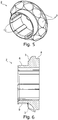
- a profile head 1 of a belt retractor is shown with a pin 14 for supporting the profile head 1 on a housing of the belt retractor.
- a blocking pawl receptacle 15 is formed, in which a belt-sensitive and / or vehicle-sensitive controllable blocking pawl can be arranged.
- the profile head 1 On a side opposite the pin 14 and the blocking pawl receptacle 15, the profile head 1 has an annular projection 4, in the interior of which a torsion bar can be inserted and fixed with one end.
- the projection 4 On its outer circumference, the projection 4 has axially extending grooves 11, to which the end faces 5 in an end region 5 of the projection 4 deformation elements 13 are in alignment with the grooves 11.
- an annular slot 7 surrounding the projection 4 is formed.
- the push-on ring 2 comprises an axially projecting, annular push-on sleeve 6.
- the push-on sleeve 6 has a length 9.
- the push-on ring 2 has axially extending springs 12, which correspond to the grooves 11 on the profile head 1.
- On one of the pusher sleeve 6 opposite side of the pusher ring 2 has an integrally formed on it bearing ring 8.
- a tensioner drive wheel 16 is formed in two parts by the profile head 1 and the pusher ring 2.
- the deformation elements 13 are subjected to force in the circumferential direction and deformed. It can also be provided in particular that before the application of force, an unillustrated torsion bar is inserted into the interior of the projection 4, wherein the deformation elements 13 in addition to the force in the circumferential direction radially inwardly acted upon and deformed, so that the torsion bar frictionally in the Tab 4 is fixed and is connected to the profile head 1.
- the length 9 of the pusher sleeve 6 is greater than the diameter 10 of the receptacles formed by the receptacles 3 for the mass body.
- the bearing ring 8 formed on the slip-on ring 2 overlaps with a shaft body arranged radially on the outside, which is radially supported by the bearing ring 8 at least in the event of loading.
Landscapes
- Engineering & Computer Science (AREA)
- Mechanical Engineering (AREA)
- Automotive Seat Belt Assembly (AREA)
Claims (6)
- Enrouleur de ceinture de sécurité comportant un arbre de ceinture comprenant un corps d'arbre, une tête profilée (1) et une barre de torsion, ladite barre de torsion agencée dans le corps d'arbre étant raccordée au corps d'arbre par une première extrémité et à la tête profilée (1) par une deuxième extrémité, et la tête profilée (1) pouvant être bloquée à demeure par rapport au véhicule ; et comportant un prétensionneur de ceinture, une roue d'entraînement de prétensionneur (16) du prétensionneur de ceinture étant directement raccordée, solidaire en rotation, à la tête profilée (1) de l'arbre de ceinture, et des masselottes pouvant être mises en prise avec la roue d'entraînement de prétensionneur (16) d'une manière permettant une transmission de force, pour entraîner l'arbre de ceinture dans la direction d'enroulement, la roue d'entraînement de prétensionneur (16) étant constituée en deux parties à partir de la tête profilée (1) de l'arbre de ceinture et d'une bague d'insertion (2) insérée sur la tête profilée (1) et raccordée à cette dernière à force et par complémentarité de forme ; des logements partiels (3) en forme de calottes respectivement opposés et complémentaires afin de former des logements pour les masselottes étant formés au niveau de la tête profilée (1) et de la bague d'insertion (2), caractérisé en ce qu'une douille d'insertion (6) annulaire est constituée sur la bague d'insertion (2) en faisant axialement saillie pour venir en appui contre la tête profilée (1) par une face frontale de celle-ci.
- Enrouleur de ceinture de sécurité selon la revendication 1, dans lequel la tête profilée (1) de l'arbre de ceinture présente une saillie annulaire (4) saillante dans le sens axial et recevant intérieurement la barre de torsion, la bague d'insertion (2) étant totalement insérée sur la saillie annulaire (4), et au moins une section terminale (5) de la saillie (4), qui ressort de la bague d'insertion (2) insérée, est déformée plastiquement pour réaliser une liaison à force avec la bague d'insertion (2) insérée.
- Enrouleur de ceinture de sécurité selon l'une des revendications précédentes, dans lequel une fente annulaire (7) est constituée sur la tête profilée (1) pour l'emboitement d'une douille d'insertion (6) annulaire constituée sur la bague d'insertion (2) en faisant axialement saillie.
- Enrouleur de ceinture de sécurité selon la revendication 1 et 2 ou 3, dans lequel la douille d'insertion (6) présente une longueur (9) au moins égale au diamètre (10) d'un logement destiné à une masselotte constitué par deux logements partiels (3) en forme de calotte, et la douille d'insertion (6) repose intérieurement sur la saillie (4) sur la totalité de la longueur (9).
- Enrouleur de ceinture de sécurité selon l'une des revendications 2 à 4, dans lequel des rainures (11) radialement extérieures sont constituées sur la saillie (4) selon une orientation axiale afin de recevoir des ressorts (12) à étendue axiale correspondants présents sur le côté intérieur de la bague d'insertion (2), et des éléments de déformation (13) sont constitués sur l'avant de la saillie (4) de niveau avec les rainures (11) en étant plastiquement déformables afin d'assembler la tête profilée (1) avec la bague d'insertion (2) et la deuxième extrémité de la barre de torsion.
- Enrouleur de ceinture de sécurité selon l'une quelconque des revendications précédentes, dans lequel une bague d'appui (8) destinée au corps d'arbre est constituée d'un seul tenant avec la bague d'insertion (2), sur un côté de celle-ci qui est tourné vers le corps d'arbre, le corps d'arbre et la roue d'entraînement de prétensionneur en deux parties se chevauchant axialement à proximité de la bague d'appui (8).
Applications Claiming Priority (2)
| Application Number | Priority Date | Filing Date | Title |
|---|---|---|---|
| DE102014114140.7A DE102014114140B4 (de) | 2014-09-29 | 2014-09-29 | Gurtaufroller mit zweiteiligem Strafferantriebsrad |
| PCT/EP2015/072220 WO2016050675A1 (fr) | 2014-09-29 | 2015-09-28 | Enrouleur de ceinture de sécurité muni d'une roue d'entraînement de prétensionneur en deux parties |
Publications (2)
| Publication Number | Publication Date |
|---|---|
| EP3201051A1 EP3201051A1 (fr) | 2017-08-09 |
| EP3201051B1 true EP3201051B1 (fr) | 2018-12-05 |
Family
ID=54252268
Family Applications (1)
| Application Number | Title | Priority Date | Filing Date |
|---|---|---|---|
| EP15775140.5A Active EP3201051B1 (fr) | 2014-09-29 | 2015-09-28 | Enrouleur de ceinture de sécurité muni d'une roue d'entraînement de prétensionneur en deux parties |
Country Status (5)
| Country | Link |
|---|---|
| US (1) | US10343647B2 (fr) |
| EP (1) | EP3201051B1 (fr) |
| CN (1) | CN106715204B (fr) |
| DE (1) | DE102014114140B4 (fr) |
| WO (1) | WO2016050675A1 (fr) |
Families Citing this family (3)
| Publication number | Priority date | Publication date | Assignee | Title |
|---|---|---|---|---|
| CN107571835B (zh) * | 2016-07-05 | 2020-05-15 | 奥托立夫开发公司 | 传动轮以及使用该传动轮的预紧式安全带的卷收器 |
| DE102019211852B3 (de) * | 2019-08-07 | 2020-12-10 | Autoliv Development Ab | Gurtaufroller |
| CN111891873B (zh) * | 2020-08-05 | 2022-01-25 | 鹤山扬阳智能机械装备有限公司 | 一种电梯制动组件 |
Family Cites Families (17)
| Publication number | Priority date | Publication date | Assignee | Title |
|---|---|---|---|---|
| DE19512660C2 (de) * | 1994-04-11 | 1999-11-18 | Autoliv Dev | Pyrotechnischer Rotationsstraffer mit Massekörperantrieb |
| US5881962A (en) * | 1994-04-11 | 1999-03-16 | Autoliv Development Ab | Mass-body drive for a rotary tightening device |
| BR9507354A (pt) | 1994-04-11 | 1997-09-09 | Autoliv Dev | Acionamento de corpo sólido para um dispositivo rotativo de aperto |
| US5601251A (en) * | 1995-03-31 | 1997-02-11 | Trw Vehicle Safety Systems Inc. | Adjustable automatic locking retractor |
| DE20003453U1 (de) * | 1999-02-26 | 2000-07-13 | Takata Corp., Minato-Ku, Tokio/Tokyo | Straffer |
| DE10213906B4 (de) * | 2002-03-28 | 2006-11-23 | Autoliv Development Ab | Leistungsstraffer |
| JP4166096B2 (ja) * | 2003-01-31 | 2008-10-15 | 芦森工業株式会社 | シートベルトリトラクター |
| DE102008059386B3 (de) | 2008-11-27 | 2010-07-01 | Autoliv Development Ab | Gurtaufroller mit einer Kraftbegrenzungseinrichtung |
| US20100176236A1 (en) * | 2009-01-09 | 2010-07-15 | Autoliv Asp, Inc. | High performance tightener |
| WO2010119778A1 (fr) * | 2009-04-17 | 2010-10-21 | オートリブ ディベロップメント エービー | Enrouleur de ceinture de sécurité |
| US9114780B2 (en) * | 2009-10-30 | 2015-08-25 | Autoliv Development Ab | Pretensioner device for a seat belt |
| DE102010051418A1 (de) * | 2010-11-17 | 2012-05-24 | Trw Automotive Gmbh | Gurtaufroller für ein Sicherheitsgurtsystem und Verfahren zur Montage eines Gurtaufrollers |
| DE102011008405B4 (de) * | 2011-01-12 | 2020-10-15 | Autoliv Development Ab | Gurtaufroller mit einer geschwindigkeitsgeregelten Kraftbegrenzungseinrichtung |
| DE102012217261B4 (de) * | 2012-09-25 | 2018-10-11 | Autoliv Development Ab | Gurtstraffer für einen Gurtaufroller |
| DE102013220949B4 (de) * | 2013-10-16 | 2021-07-08 | Autoliv Development Ab | Kraftbegrenzungseinrichtung für ein Sicherheitsgurtsystem |
| US9555768B2 (en) * | 2014-05-23 | 2017-01-31 | Autoliv Asp, Inc. | Retractor pretensioner assembly |
| US9744940B1 (en) * | 2016-04-13 | 2017-08-29 | Autoliv Asp, Inc. | Seatbelt pretensioning retractor assembly |
-
2014
- 2014-09-29 DE DE102014114140.7A patent/DE102014114140B4/de active Active
-
2015
- 2015-09-28 US US15/514,832 patent/US10343647B2/en active Active
- 2015-09-28 EP EP15775140.5A patent/EP3201051B1/fr active Active
- 2015-09-28 CN CN201580052571.2A patent/CN106715204B/zh active Active
- 2015-09-28 WO PCT/EP2015/072220 patent/WO2016050675A1/fr active Application Filing
Non-Patent Citations (1)
| Title |
|---|
| None * |
Also Published As
| Publication number | Publication date |
|---|---|
| CN106715204A (zh) | 2017-05-24 |
| US20170313279A1 (en) | 2017-11-02 |
| US10343647B2 (en) | 2019-07-09 |
| WO2016050675A1 (fr) | 2016-04-07 |
| DE102014114140B4 (de) | 2017-01-05 |
| EP3201051A1 (fr) | 2017-08-09 |
| CN106715204B (zh) | 2020-02-14 |
| DE102014114140A1 (de) | 2016-03-31 |
Similar Documents
| Publication | Publication Date | Title |
|---|---|---|
| WO2016045673A1 (fr) | Vis à billes | |
| DE102015219930B4 (de) | Freilaufvorrichtung für ein Kraftfahrzeug | |
| EP3631219B1 (fr) | Arbre de direction pour un véhicule automobile | |
| EP3201051B1 (fr) | Enrouleur de ceinture de sécurité muni d'une roue d'entraînement de prétensionneur en deux parties | |
| DE102008057222B4 (de) | Lageranordnung | |
| EP2615346B1 (fr) | Collier à bande élastique | |
| EP2867546A1 (fr) | Circlip | |
| DE102015209252B4 (de) | Strafferantrieb für eine Sicherheitsgurteinrichtung | |
| WO2021052527A1 (fr) | Ensemble roue libre à flasque embouti profond | |
| DE102007023972A1 (de) | Verfahren zur Herstellung einer Nabe im Drückverfahren mittels wenigstens einer drehbaren Drückrolle | |
| DE102013205690B4 (de) | Gurtaufroller mit einer Kraftbegrenzungseinrichtung | |
| DE102012215395A1 (de) | Kugelgewindetrieb | |
| DE102016104614B4 (de) | Gurtaufroller mit einer Kraftbegrenzungseinrichtung | |
| DE102008025266A1 (de) | Lageranordnung und Montageverfahren | |
| DE102006031525B4 (de) | Lageraufnahme | |
| EP3568331B1 (fr) | Arbre de direction pour un véhicule automobile | |
| DE102018107765B3 (de) | Getriebeanordnung für eine Vorrichtung zur Niveauverstellung eines Fahrzeugaufbaus | |
| EP2395255B1 (fr) | Fixation axiale amovible de deux composants | |
| EP2299138B1 (fr) | Unité de montage pour boîtes de vitesse de véhicule automobile | |
| DE102009017137A1 (de) | Gurtstraffer für einen Gurtaufroller | |
| DE102018102577A1 (de) | Kupplungsvorrichtung | |
| DE102015222301B4 (de) | Rollenfreilauf | |
| DE102022101203B4 (de) | Gurtaufroller für eine Sicherheitsgurteinrichtung eines Kraftfahrzeuges | |
| DE102008020853A1 (de) | Wälzlager zur Lagerung einer Lenkwelle eines Kraftfahrzeugs und Toleranzring | |
| DE10238101B4 (de) | Sicherungsring |
Legal Events
| Date | Code | Title | Description |
|---|---|---|---|
| STAA | Information on the status of an ep patent application or granted ep patent |
Free format text: STATUS: THE INTERNATIONAL PUBLICATION HAS BEEN MADE |
|
| PUAI | Public reference made under article 153(3) epc to a published international application that has entered the european phase |
Free format text: ORIGINAL CODE: 0009012 |
|
| STAA | Information on the status of an ep patent application or granted ep patent |
Free format text: STATUS: REQUEST FOR EXAMINATION WAS MADE |
|
| 17P | Request for examination filed |
Effective date: 20170315 |
|
| AK | Designated contracting states |
Kind code of ref document: A1 Designated state(s): AL AT BE BG CH CY CZ DE DK EE ES FI FR GB GR HR HU IE IS IT LI LT LU LV MC MK MT NL NO PL PT RO RS SE SI SK SM TR |
|
| AX | Request for extension of the european patent |
Extension state: BA ME |
|
| RIN1 | Information on inventor provided before grant (corrected) |
Inventor name: WULFF, FRANK Inventor name: TRUEBNER, CLAUDIA Inventor name: KRAUS, JURI Inventor name: KUBBE, THOMAS Inventor name: SCHUBEL, KARSTEN |
|
| DAV | Request for validation of the european patent (deleted) | ||
| DAX | Request for extension of the european patent (deleted) | ||
| GRAP | Despatch of communication of intention to grant a patent |
Free format text: ORIGINAL CODE: EPIDOSNIGR1 |
|
| STAA | Information on the status of an ep patent application or granted ep patent |
Free format text: STATUS: GRANT OF PATENT IS INTENDED |
|
| INTG | Intention to grant announced |
Effective date: 20180627 |
|
| GRAS | Grant fee paid |
Free format text: ORIGINAL CODE: EPIDOSNIGR3 |
|
| GRAA | (expected) grant |
Free format text: ORIGINAL CODE: 0009210 |
|
| STAA | Information on the status of an ep patent application or granted ep patent |
Free format text: STATUS: THE PATENT HAS BEEN GRANTED |
|
| AK | Designated contracting states |
Kind code of ref document: B1 Designated state(s): AL AT BE BG CH CY CZ DE DK EE ES FI FR GB GR HR HU IE IS IT LI LT LU LV MC MK MT NL NO PL PT RO RS SE SI SK SM TR |
|
| REG | Reference to a national code |
Ref country code: GB Ref legal event code: FG4D Free format text: NOT ENGLISH |
|
| REG | Reference to a national code |
Ref country code: CH Ref legal event code: EP |
|
| REG | Reference to a national code |
Ref country code: AT Ref legal event code: REF Ref document number: 1072622 Country of ref document: AT Kind code of ref document: T Effective date: 20181215 |
|
| REG | Reference to a national code |
Ref country code: IE Ref legal event code: FG4D Free format text: LANGUAGE OF EP DOCUMENT: GERMAN |
|
| REG | Reference to a national code |
Ref country code: DE Ref legal event code: R096 Ref document number: 502015007136 Country of ref document: DE |
|
| REG | Reference to a national code |
Ref country code: NL Ref legal event code: MP Effective date: 20181205 |
|
| REG | Reference to a national code |
Ref country code: LT Ref legal event code: MG4D |
|
| PG25 | Lapsed in a contracting state [announced via postgrant information from national office to epo] |
Ref country code: BG Free format text: LAPSE BECAUSE OF FAILURE TO SUBMIT A TRANSLATION OF THE DESCRIPTION OR TO PAY THE FEE WITHIN THE PRESCRIBED TIME-LIMIT Effective date: 20190305 Ref country code: LT Free format text: LAPSE BECAUSE OF FAILURE TO SUBMIT A TRANSLATION OF THE DESCRIPTION OR TO PAY THE FEE WITHIN THE PRESCRIBED TIME-LIMIT Effective date: 20181205 Ref country code: FI Free format text: LAPSE BECAUSE OF FAILURE TO SUBMIT A TRANSLATION OF THE DESCRIPTION OR TO PAY THE FEE WITHIN THE PRESCRIBED TIME-LIMIT Effective date: 20181205 Ref country code: NO Free format text: LAPSE BECAUSE OF FAILURE TO SUBMIT A TRANSLATION OF THE DESCRIPTION OR TO PAY THE FEE WITHIN THE PRESCRIBED TIME-LIMIT Effective date: 20190305 Ref country code: ES Free format text: LAPSE BECAUSE OF FAILURE TO SUBMIT A TRANSLATION OF THE DESCRIPTION OR TO PAY THE FEE WITHIN THE PRESCRIBED TIME-LIMIT Effective date: 20181205 Ref country code: HR Free format text: LAPSE BECAUSE OF FAILURE TO SUBMIT A TRANSLATION OF THE DESCRIPTION OR TO PAY THE FEE WITHIN THE PRESCRIBED TIME-LIMIT Effective date: 20181205 Ref country code: LV Free format text: LAPSE BECAUSE OF FAILURE TO SUBMIT A TRANSLATION OF THE DESCRIPTION OR TO PAY THE FEE WITHIN THE PRESCRIBED TIME-LIMIT Effective date: 20181205 |
|
| PG25 | Lapsed in a contracting state [announced via postgrant information from national office to epo] |
Ref country code: AL Free format text: LAPSE BECAUSE OF FAILURE TO SUBMIT A TRANSLATION OF THE DESCRIPTION OR TO PAY THE FEE WITHIN THE PRESCRIBED TIME-LIMIT Effective date: 20181205 Ref country code: SE Free format text: LAPSE BECAUSE OF FAILURE TO SUBMIT A TRANSLATION OF THE DESCRIPTION OR TO PAY THE FEE WITHIN THE PRESCRIBED TIME-LIMIT Effective date: 20181205 Ref country code: RS Free format text: LAPSE BECAUSE OF FAILURE TO SUBMIT A TRANSLATION OF THE DESCRIPTION OR TO PAY THE FEE WITHIN THE PRESCRIBED TIME-LIMIT Effective date: 20181205 Ref country code: GR Free format text: LAPSE BECAUSE OF FAILURE TO SUBMIT A TRANSLATION OF THE DESCRIPTION OR TO PAY THE FEE WITHIN THE PRESCRIBED TIME-LIMIT Effective date: 20190306 |
|
| PG25 | Lapsed in a contracting state [announced via postgrant information from national office to epo] |
Ref country code: NL Free format text: LAPSE BECAUSE OF FAILURE TO SUBMIT A TRANSLATION OF THE DESCRIPTION OR TO PAY THE FEE WITHIN THE PRESCRIBED TIME-LIMIT Effective date: 20181205 |
|
| PG25 | Lapsed in a contracting state [announced via postgrant information from national office to epo] |
Ref country code: PL Free format text: LAPSE BECAUSE OF FAILURE TO SUBMIT A TRANSLATION OF THE DESCRIPTION OR TO PAY THE FEE WITHIN THE PRESCRIBED TIME-LIMIT Effective date: 20181205 Ref country code: CZ Free format text: LAPSE BECAUSE OF FAILURE TO SUBMIT A TRANSLATION OF THE DESCRIPTION OR TO PAY THE FEE WITHIN THE PRESCRIBED TIME-LIMIT Effective date: 20181205 Ref country code: IT Free format text: LAPSE BECAUSE OF FAILURE TO SUBMIT A TRANSLATION OF THE DESCRIPTION OR TO PAY THE FEE WITHIN THE PRESCRIBED TIME-LIMIT Effective date: 20181205 Ref country code: PT Free format text: LAPSE BECAUSE OF FAILURE TO SUBMIT A TRANSLATION OF THE DESCRIPTION OR TO PAY THE FEE WITHIN THE PRESCRIBED TIME-LIMIT Effective date: 20190405 |
|
| PG25 | Lapsed in a contracting state [announced via postgrant information from national office to epo] |
Ref country code: SM Free format text: LAPSE BECAUSE OF FAILURE TO SUBMIT A TRANSLATION OF THE DESCRIPTION OR TO PAY THE FEE WITHIN THE PRESCRIBED TIME-LIMIT Effective date: 20181205 Ref country code: EE Free format text: LAPSE BECAUSE OF FAILURE TO SUBMIT A TRANSLATION OF THE DESCRIPTION OR TO PAY THE FEE WITHIN THE PRESCRIBED TIME-LIMIT Effective date: 20181205 Ref country code: RO Free format text: LAPSE BECAUSE OF FAILURE TO SUBMIT A TRANSLATION OF THE DESCRIPTION OR TO PAY THE FEE WITHIN THE PRESCRIBED TIME-LIMIT Effective date: 20181205 Ref country code: IS Free format text: LAPSE BECAUSE OF FAILURE TO SUBMIT A TRANSLATION OF THE DESCRIPTION OR TO PAY THE FEE WITHIN THE PRESCRIBED TIME-LIMIT Effective date: 20190405 Ref country code: SK Free format text: LAPSE BECAUSE OF FAILURE TO SUBMIT A TRANSLATION OF THE DESCRIPTION OR TO PAY THE FEE WITHIN THE PRESCRIBED TIME-LIMIT Effective date: 20181205 |
|
| REG | Reference to a national code |
Ref country code: DE Ref legal event code: R097 Ref document number: 502015007136 Country of ref document: DE |
|
| PLBE | No opposition filed within time limit |
Free format text: ORIGINAL CODE: 0009261 |
|
| STAA | Information on the status of an ep patent application or granted ep patent |
Free format text: STATUS: NO OPPOSITION FILED WITHIN TIME LIMIT |
|
| PG25 | Lapsed in a contracting state [announced via postgrant information from national office to epo] |
Ref country code: DK Free format text: LAPSE BECAUSE OF FAILURE TO SUBMIT A TRANSLATION OF THE DESCRIPTION OR TO PAY THE FEE WITHIN THE PRESCRIBED TIME-LIMIT Effective date: 20181205 Ref country code: SI Free format text: LAPSE BECAUSE OF FAILURE TO SUBMIT A TRANSLATION OF THE DESCRIPTION OR TO PAY THE FEE WITHIN THE PRESCRIBED TIME-LIMIT Effective date: 20181205 |
|
| 26N | No opposition filed |
Effective date: 20190906 |
|
| PG25 | Lapsed in a contracting state [announced via postgrant information from national office to epo] |
Ref country code: TR Free format text: LAPSE BECAUSE OF FAILURE TO SUBMIT A TRANSLATION OF THE DESCRIPTION OR TO PAY THE FEE WITHIN THE PRESCRIBED TIME-LIMIT Effective date: 20181205 |
|
| PG25 | Lapsed in a contracting state [announced via postgrant information from national office to epo] |
Ref country code: MC Free format text: LAPSE BECAUSE OF FAILURE TO SUBMIT A TRANSLATION OF THE DESCRIPTION OR TO PAY THE FEE WITHIN THE PRESCRIBED TIME-LIMIT Effective date: 20181205 |
|
| REG | Reference to a national code |
Ref country code: CH Ref legal event code: PL |
|
| PG25 | Lapsed in a contracting state [announced via postgrant information from national office to epo] |
Ref country code: LU Free format text: LAPSE BECAUSE OF NON-PAYMENT OF DUE FEES Effective date: 20190928 Ref country code: IE Free format text: LAPSE BECAUSE OF NON-PAYMENT OF DUE FEES Effective date: 20190928 Ref country code: CH Free format text: LAPSE BECAUSE OF NON-PAYMENT OF DUE FEES Effective date: 20190930 Ref country code: LI Free format text: LAPSE BECAUSE OF NON-PAYMENT OF DUE FEES Effective date: 20190930 |
|
| REG | Reference to a national code |
Ref country code: BE Ref legal event code: MM Effective date: 20190930 |
|
| PG25 | Lapsed in a contracting state [announced via postgrant information from national office to epo] |
Ref country code: BE Free format text: LAPSE BECAUSE OF NON-PAYMENT OF DUE FEES Effective date: 20190930 |
|
| PG25 | Lapsed in a contracting state [announced via postgrant information from national office to epo] |
Ref country code: CY Free format text: LAPSE BECAUSE OF FAILURE TO SUBMIT A TRANSLATION OF THE DESCRIPTION OR TO PAY THE FEE WITHIN THE PRESCRIBED TIME-LIMIT Effective date: 20181205 |
|
| PG25 | Lapsed in a contracting state [announced via postgrant information from national office to epo] |
Ref country code: MT Free format text: LAPSE BECAUSE OF FAILURE TO SUBMIT A TRANSLATION OF THE DESCRIPTION OR TO PAY THE FEE WITHIN THE PRESCRIBED TIME-LIMIT Effective date: 20181205 Ref country code: HU Free format text: LAPSE BECAUSE OF FAILURE TO SUBMIT A TRANSLATION OF THE DESCRIPTION OR TO PAY THE FEE WITHIN THE PRESCRIBED TIME-LIMIT; INVALID AB INITIO Effective date: 20150928 |
|
| REG | Reference to a national code |
Ref country code: AT Ref legal event code: MM01 Ref document number: 1072622 Country of ref document: AT Kind code of ref document: T Effective date: 20200928 |
|
| PG25 | Lapsed in a contracting state [announced via postgrant information from national office to epo] |
Ref country code: AT Free format text: LAPSE BECAUSE OF NON-PAYMENT OF DUE FEES Effective date: 20200928 |
|
| PG25 | Lapsed in a contracting state [announced via postgrant information from national office to epo] |
Ref country code: MK Free format text: LAPSE BECAUSE OF FAILURE TO SUBMIT A TRANSLATION OF THE DESCRIPTION OR TO PAY THE FEE WITHIN THE PRESCRIBED TIME-LIMIT Effective date: 20181205 |
|
| PGFP | Annual fee paid to national office [announced via postgrant information from national office to epo] |
Ref country code: GB Payment date: 20220927 Year of fee payment: 8 |
|
| P01 | Opt-out of the competence of the unified patent court (upc) registered |
Effective date: 20230507 |
|
| PGFP | Annual fee paid to national office [announced via postgrant information from national office to epo] |
Ref country code: FR Payment date: 20230926 Year of fee payment: 9 Ref country code: DE Payment date: 20230928 Year of fee payment: 9 |
|
| GBPC | Gb: european patent ceased through non-payment of renewal fee |
Effective date: 20230928 |
|
| PG25 | Lapsed in a contracting state [announced via postgrant information from national office to epo] |
Ref country code: GB Free format text: LAPSE BECAUSE OF NON-PAYMENT OF DUE FEES Effective date: 20230928 |
|
| PG25 | Lapsed in a contracting state [announced via postgrant information from national office to epo] |
Ref country code: GB Free format text: LAPSE BECAUSE OF NON-PAYMENT OF DUE FEES Effective date: 20230928 |