EP3201051B1 - Belt retractor with two-part tensioning drive wheel - Google Patents
Belt retractor with two-part tensioning drive wheel Download PDFInfo
- Publication number
- EP3201051B1 EP3201051B1 EP15775140.5A EP15775140A EP3201051B1 EP 3201051 B1 EP3201051 B1 EP 3201051B1 EP 15775140 A EP15775140 A EP 15775140A EP 3201051 B1 EP3201051 B1 EP 3201051B1
- Authority
- EP
- European Patent Office
- Prior art keywords
- push
- ring
- profile head
- belt
- projection
- Prior art date
- Legal status (The legal status is an assumption and is not a legal conclusion. Google has not performed a legal analysis and makes no representation as to the accuracy of the status listed.)
- Active
Links
- 239000007787 solid Substances 0.000 claims 2
- 230000000903 blocking effect Effects 0.000 description 4
- 238000011161 development Methods 0.000 description 2
- 230000018109 developmental process Effects 0.000 description 2
- 238000004804 winding Methods 0.000 description 2
- 230000001133 acceleration Effects 0.000 description 1
- 230000000295 complement effect Effects 0.000 description 1
- 230000003750 conditioning effect Effects 0.000 description 1
- 238000002788 crimping Methods 0.000 description 1
- 230000006378 damage Effects 0.000 description 1
- 230000001419 dependent effect Effects 0.000 description 1
- 210000003746 feather Anatomy 0.000 description 1
Images


Classifications
-
- B—PERFORMING OPERATIONS; TRANSPORTING
- B60—VEHICLES IN GENERAL
- B60R—VEHICLES, VEHICLE FITTINGS, OR VEHICLE PARTS, NOT OTHERWISE PROVIDED FOR
- B60R22/00—Safety belts or body harnesses in vehicles
- B60R22/34—Belt retractors, e.g. reels
- B60R22/46—Reels with means to tension the belt in an emergency by forced winding up
- B60R22/4671—Reels with means to tension the belt in an emergency by forced winding up characterised by spring actuators
-
- B—PERFORMING OPERATIONS; TRANSPORTING
- B60—VEHICLES IN GENERAL
- B60R—VEHICLES, VEHICLE FITTINGS, OR VEHICLE PARTS, NOT OTHERWISE PROVIDED FOR
- B60R22/00—Safety belts or body harnesses in vehicles
- B60R22/34—Belt retractors, e.g. reels
- B60R22/46—Reels with means to tension the belt in an emergency by forced winding up
- B60R22/4628—Reels with means to tension the belt in an emergency by forced winding up characterised by fluid actuators, e.g. pyrotechnic gas generators
-
- B—PERFORMING OPERATIONS; TRANSPORTING
- B60—VEHICLES IN GENERAL
- B60R—VEHICLES, VEHICLE FITTINGS, OR VEHICLE PARTS, NOT OTHERWISE PROVIDED FOR
- B60R22/00—Safety belts or body harnesses in vehicles
- B60R22/28—Safety belts or body harnesses in vehicles incorporating energy-absorbing devices
- B60R2022/286—Safety belts or body harnesses in vehicles incorporating energy-absorbing devices using deformation of material
-
- B—PERFORMING OPERATIONS; TRANSPORTING
- B60—VEHICLES IN GENERAL
- B60R—VEHICLES, VEHICLE FITTINGS, OR VEHICLE PARTS, NOT OTHERWISE PROVIDED FOR
- B60R22/00—Safety belts or body harnesses in vehicles
- B60R22/34—Belt retractors, e.g. reels
- B60R22/46—Reels with means to tension the belt in an emergency by forced winding up
- B60R22/4628—Reels with means to tension the belt in an emergency by forced winding up characterised by fluid actuators, e.g. pyrotechnic gas generators
- B60R2022/4642—Reels with means to tension the belt in an emergency by forced winding up characterised by fluid actuators, e.g. pyrotechnic gas generators the gas directly propelling a flexible driving means, e.g. a plurality of successive masses, in a tubular chamber
Definitions
- the present invention relates to a belt retractor comprising a belt shaft comprising a shaft body, a profile head and a torsion bar, wherein the torsion bar arranged in the shaft body is connected to the shaft body at a first end and to the profile head at a second end and the profile head can be locked in a vehicle-fixed manner, and with a belt tensioner, wherein a tensioner drive of the belt tensioner is rotatably connected directly to the profile head of the belt shaft and wherein for driving the belt shaft in the winding mass mass transferring force can be brought into engagement with the Strafferantriebsrad, the Strafferantriebsrad in two parts from the profile head of the belt shaft and on the Profile head deferred and formed positively and positively connected with this slip-on, wherein on the profile head and on the slip ring each opposite, complementary to recordings for the mass body, dome-shaped Operaau are shaped.
- a belt retractor is off DE 10 2008 059 386 B3 known, wherein a one-piece Strafferantriebsrad is pushed onto the profile head and is secured there by a separate bearing ring on which the shaft body rolls in its relative movement to the blocked profile head. There are thus a plurality of parts to postpone during assembly on the profile head.
- Object of the present invention is therefore to solve the problem described with reference to the prior art and in particular to provide a belt retractor, which is easy to assemble and which has a smaller footprint.
- the present invention is thus directed to a belt retractor, wherein the vehicle fixed blockable profile head and the tensioner wheel are arranged on the same side of the shaft body, wherein additionally a force-limiting Torsionsstab between the profile head and the shaft body is provided. So far as the torsion bar limits the force acting on the occupant in the event of an acceleration when the profile head is locked in the vehicle, the belt tensioner can wind up the webbing if necessary by driving the belt shaft.
- the tensioner wheel consists of two parts.
- the first part is the profile head of the belt shaft, and the second part is the pusher ring.
- the pusher ring For positively fixing the pusher ring on the profile head against a relative movement in the circumferential direction of the profile head and the pusher ring recesses and corresponding elevations.
- the profile head and the pusher ring on dome-shaped part recordings which together form a pair of receptacles for the mass body of the belt tensioner.
- the profile head provided with the pusher ring has a smaller footprint.
- no additional component for fixing the tensioner drive on the profile head necessary.
- the profile head of the belt shaft has an axially projecting, the Torsionsstab inside receiving, annular projection and the pusher ring is completely pushed onto the annular projection, wherein at least one on the deferred pusher ring protruding end portion of the projection for frictional connection with the pushed-slip ring is plastically deformed.
- the projection thus serves, on the one hand, for the positive connection of the torsion bar with the profile head in the interior and, on the other, for pushing on the push-on ring, the end area being plastically deformed for fixing both the push-on ring and, in particular, the torsion bar.
- annular slot is formed on the profile head, in which an axially projecting, annular pusher sleeve formed on the pusher ring is inserted.
- the annular slot extends directly adjacent to the projection of the profile head and holds the slide ring in particular during crimping or caulking of the projection in the predetermined position.
- a particularly secure connection between the slip ring and the profile head is achieved in this context, when the push-on sleeve has a length which is at least as large as a diameter of a formed by two dome-shaped part recordings receptacle for a mass body, and the extension sleeve over the entire length inside abuts the projection.
- a bearing ring for the shaft body is integrally formed on the slide ring on a side facing the shaft body, wherein the shaft body and the two-piece Strafferantriebsrad axially overlap in the region of the bearing ring.
- a profile head 1 of a belt retractor is shown with a pin 14 for supporting the profile head 1 on a housing of the belt retractor.
- a blocking pawl receptacle 15 is formed, in which a belt-sensitive and / or vehicle-sensitive controllable blocking pawl can be arranged.
- the profile head 1 On a side opposite the pin 14 and the blocking pawl receptacle 15, the profile head 1 has an annular projection 4, in the interior of which a torsion bar can be inserted and fixed with one end.
- the projection 4 On its outer circumference, the projection 4 has axially extending grooves 11, to which the end faces 5 in an end region 5 of the projection 4 deformation elements 13 are in alignment with the grooves 11.
- an annular slot 7 surrounding the projection 4 is formed.
- the push-on ring 2 comprises an axially projecting, annular push-on sleeve 6.
- the push-on sleeve 6 has a length 9.
- the push-on ring 2 has axially extending springs 12, which correspond to the grooves 11 on the profile head 1.
- On one of the pusher sleeve 6 opposite side of the pusher ring 2 has an integrally formed on it bearing ring 8.
- a tensioner drive wheel 16 is formed in two parts by the profile head 1 and the pusher ring 2.
- the deformation elements 13 are subjected to force in the circumferential direction and deformed. It can also be provided in particular that before the application of force, an unillustrated torsion bar is inserted into the interior of the projection 4, wherein the deformation elements 13 in addition to the force in the circumferential direction radially inwardly acted upon and deformed, so that the torsion bar frictionally in the Tab 4 is fixed and is connected to the profile head 1.
- the length 9 of the pusher sleeve 6 is greater than the diameter 10 of the receptacles formed by the receptacles 3 for the mass body.
- the bearing ring 8 formed on the slip-on ring 2 overlaps with a shaft body arranged radially on the outside, which is radially supported by the bearing ring 8 at least in the event of loading.
Description
Die vorliegende Erfindung betrifft einen Gurtaufroller mit einer einen Wellenkörper, einen Profilkopf und einen Torsionsstab umfassenden Gurtwelle, wobei der in dem Wellenkörper angeordnete Torsionsstab mit einem ersten Ende mit dem Wellenkörper und mit einem zweiten Ende mit dem Profilkopf verbunden ist und der Profilkopf fahrzeugfest blockierbar ist, und mit einem Gurtstraffer, wobei ein Strafferantriebsrad des Gurtstraffers unmittelbar mit dem Profilkopf der Gurtwelle drehfest verbunden ist und wobei zum Antreiben der Gurtwelle in Aufwickelrichtung Massekörper kraftübertragend in Eingriff mit dem Strafferantriebsrad bringbar sind, wobei das Strafferantriebsrad zweiteilig aus dem Profilkopf der Gurtwelle und einem auf den Profilkopf aufgeschobenen und mit diesem kraft- und formschlüssig verbundenen Aufschubring ausgebildet ist, wobei an dem Profilkopf und an dem Aufschubring jeweils gegenüberliegende, sich zu Aufnahmen für die Massekörper ergänzende, kalottenförmige Teilaufnahmen geformt sind.The present invention relates to a belt retractor comprising a belt shaft comprising a shaft body, a profile head and a torsion bar, wherein the torsion bar arranged in the shaft body is connected to the shaft body at a first end and to the profile head at a second end and the profile head can be locked in a vehicle-fixed manner, and with a belt tensioner, wherein a tensioner drive of the belt tensioner is rotatably connected directly to the profile head of the belt shaft and wherein for driving the belt shaft in the winding mass mass transferring force can be brought into engagement with the Strafferantriebsrad, the Strafferantriebsrad in two parts from the profile head of the belt shaft and on the Profile head deferred and formed positively and positively connected with this slip-on, wherein on the profile head and on the slip ring each opposite, complementary to recordings for the mass body, dome-shaped Teilau are shaped.
Ein Gurtaufroller ist beispielsweise aus
Soweit aus
Ein Gurtaufroller mit den eingangs genannten Merkmalen ist aus
Aufgabe der vorliegenden Erfindung ist es daher, das mit Bezug zum Stand der Technik geschilderte Problem zu lösen und insbesondere einen Gurtaufroller anzugeben, welcher einfach zu montieren ist und welcher einen geringeren Platzbedarf aufweist.Object of the present invention is therefore to solve the problem described with reference to the prior art and in particular to provide a belt retractor, which is easy to assemble and which has a smaller footprint.
Gelöst werden die Aufgaben durch einen Gurtaufroller mit den Merkmalen des unabhängigen Anspruchs. Vorteilhafte Weiterbildungen des Gurtaufrollers sind in den abhängigen Ansprüchen und in der Beschreibung angegeben, wobei Merkmale der vorteilhaften Weiterbildungen in technologisch sinnvoller Weise beliebig miteinander kombinierbar sind.The objects are achieved by a belt retractor with the features of the independent claim. Advantageous developments of the belt retractor are specified in the dependent claims and in the description, wherein features of the advantageous developments in a technologically meaningful manner are combined with each other as desired.
Gelöst werden diese Aufgaben mit einem Gurtaufroller mit den eingangs genannten Merkmalen, wobei an dem Aufschubring eine axial vorragende, ringförmige Aufschubhülse ausgebildet ist, die mit einer stirnseitigen Fläche in Anlage mit dem Profilkopf ist. Durch die stirnseitige Anlage ist zum einen die Position der Aufschubhülse und damit die Position des Aufschubringes auf dem Vorsprung vorgegeben und zum anderen kann somit ein umlaufender Spalt zwischen den Teilaufnahmen an dem Profilkopf einerseits und den Teilaufnahmen an dem Aufschubring andererseits ausgebildet werden.These objects are achieved with a belt retractor with the features mentioned, wherein on the pusher an axially projecting, annular pusher sleeve is formed, which is in contact with the profile head with an end face. By the frontal conditioning is on the one hand, the position of the pusher and thus the position of the pusher set on the projection and on the other hand thus a circumferential gap between the partial receptacles on the profile head on the one hand and the partial receptacles on the pusher ring on the other.
Die vorliegende Erfindung ist also auf einem Gurtaufroller gerichtet, bei dem der fahrzeugfest blockierbare Profilkopf und das Strafferantriebsrad auf der gleichen Seite des Wellenkörpers angeordnet sind, wobei zusätzlich ein kraftbegrenzender Torsionsstab zwischen dem Profilkopf und dem Wellenkörper vorgesehen ist. Soweit also der Torsionsstab im Beschleunigungsfall bei fahrzeugfest blockiertem Profilkopf die Krafteinwirkung auf den Insassen begrenzt, kann der Gurtstraffer das Gurtband bei Bedarf durch Antreiben der Gurtwelle aufwickeln.The present invention is thus directed to a belt retractor, wherein the vehicle fixed blockable profile head and the tensioner wheel are arranged on the same side of the shaft body, wherein additionally a force-limiting Torsionsstab between the profile head and the shaft body is provided. So far as the torsion bar limits the force acting on the occupant in the event of an acceleration when the profile head is locked in the vehicle, the belt tensioner can wind up the webbing if necessary by driving the belt shaft.
Die vorliegende Erfindung sieht nun vor, dass das Strafferantriebsrad aus zwei Teilen besteht. Das erste Teil ist der Profilkopf der Gurtwelle, und das zweite Teil ist der Aufschubring. Zur formschlüssigen Festlegung des Aufschubringes auf den Profilkopf gegen eine Relativbewegung in Umfangsrichtung weisen der Profilkopf und der Aufschubring Ausnehmungen und entsprechende Erhebungen auf. Um den Profilkopf mit dem Aufschubring insbesondere in axialer Richtung miteinander kraftschlüssig zu verbinden, kann insbesondere ein Ende des Profilkopfes verstemmt beziehungsweise gekrimpt werden, so dass aufgrund der plastischen Verformung des Profilkopfes der Aufschubring nicht mehr zerstörungsfrei von dem Profilkopf gelöst werden kann. Um die Funktion des einteiligen Strafferantriebsrades zu erreichen, weisen der Profilkopf und der Aufschubring kalottenförmige Teilaufnahmen auf, die jeweils paarweise zusammen eine Aufnahme für die Massekörper des Gurtstraffers ausbilden.The present invention now provides that the tensioner wheel consists of two parts. The first part is the profile head of the belt shaft, and the second part is the pusher ring. For positively fixing the pusher ring on the profile head against a relative movement in the circumferential direction of the profile head and the pusher ring recesses and corresponding elevations. To connect the profile head with the pusher ring in particular in the axial direction with each other, in particular one end of the profile head can be caulked or crimped, so that due to the plastic deformation of the profile head of the pusher ring can not be solved without destruction of the profile head. In order to achieve the function of the one-piece tensioner drive, the profile head and the pusher ring on dome-shaped part recordings, which together form a pair of receptacles for the mass body of the belt tensioner.
Dadurch, dass die kalottenförmigen Teilaufnahmen unmittelbar an dem Profilkopf ausgebildet werden können, weist der mit dem Aufschubring versehene Profilkopf einen geringeren Platzbedarf auf. Zudem ist aufgrund der form- und kraftschlüssigen Verbindung kein zusätzliches Bauteil zur Festlegung des Strafferantriebes an dem Profilkopf notwendig.Because the dome-shaped partial receptacles can be formed directly on the profile head, the profile head provided with the pusher ring has a smaller footprint. In addition, due to the positive and non-positive connection no additional component for fixing the tensioner drive on the profile head necessary.
Es kann vorgesehen sein, dass der Profilkopf der Gurtwelle einen axial vorstehenden, den Torsionsstab innen aufnehmenden, ringförmigen Vorsprung aufweist und der Aufschubring vollständig auf den ringförmigen Vorsprung aufgeschoben ist, wobei zumindest ein über den aufgeschobenen Aufschubring hervorstehender Endbereich des Vorsprungs zum kraftschlüssigen Verbinden mit dem aufgeschobenen Aufschubring plastisch verformt ist. Der Vorsprung dient also zum einen zur formschlüssigen Verbindung des Torsionsstabes mit dem Profilkopf im Inneren und zum anderen zum Aufschieben des Aufschubrings, wobei der Endbereich zur Fixierung sowohl des Aufschubringes als auch insbesondere des Torsionsstabes plastisch verformt ist.It can be provided that the profile head of the belt shaft has an axially projecting, the Torsionsstab inside receiving, annular projection and the pusher ring is completely pushed onto the annular projection, wherein at least one on the deferred pusher ring protruding end portion of the projection for frictional connection with the pushed-slip ring is plastically deformed. The projection thus serves, on the one hand, for the positive connection of the torsion bar with the profile head in the interior and, on the other, for pushing on the push-on ring, the end area being plastically deformed for fixing both the push-on ring and, in particular, the torsion bar.
Um die Position des Aufschubringes genauer vorzugeben und insbesondere um eine größere Lagerfläche des Aufschubringes gegenüber dem Profilkopf bereitzustellen, kann vorgesehen sein, dass ein ringförmiger Schlitz an dem Profilkopf ausgebildet ist, in den eine an dem Aufschubring ausgebildete, axial vorragende, ringförmige Aufschubhülse eingesteckt ist. Der ringförmige Schlitz verläuft dabei unmittelbar angrenzend an den Vorsprung des Profilkopfes und hält den Aufschubring insbesondere beim Krimpen bzw. Stemmen des Vorsprunges in der vorgegebenen Position.In order to specify the position of the pusher ring in more detail and in particular to provide a larger bearing surface of the pusher with respect to the profile head, it can be provided that an annular slot is formed on the profile head, in which an axially projecting, annular pusher sleeve formed on the pusher ring is inserted. The annular slot extends directly adjacent to the projection of the profile head and holds the slide ring in particular during crimping or caulking of the projection in the predetermined position.
Eine besonders sichere Verbindung zwischen Aufschubring und Profilkopf wird in diesem Zusammenhang erreicht, wenn die Aufschubhülse eine Länge aufweist, die mindestens so groß ist wie ein Durchmesser von einer durch zwei kalottenförmige Teilaufnahmen ausgebildeten Aufnahme für einen Massekörper, und die Aufschubhülse über die gesamte Länge innen an dem Vorsprung anliegt.A particularly secure connection between the slip ring and the profile head is achieved in this context, when the push-on sleeve has a length which is at least as large as a diameter of a formed by two dome-shaped part recordings receptacle for a mass body, and the extension sleeve over the entire length inside abuts the projection.
In einer weiteren Ausführungsform ist vorgesehen, dass radial außen an dem Vorsprung axial ausgerichtete Nuten zur Aufnahme von entsprechenden axial verlaufender Federn an der Innenseite des Aufschubrings ausgebildet sind und Verformungselemente stirnseitig an dem Vorsprung fluchtend mit den Nuten ausgebildet sind, die plastisch zum Verbinden des Profilkopfs mit dem Aufschubring und dem zweiten Ende des Torsionsstabs verformt sind. Insbesondere sind die Verformungselemente zum Verbinden des Aufschubringes mit dem Vorsprung in Umfangsrichtung plastisch verformt und zum Verbinden des Vorsprunges mit dem Torsionsstab radial nach innen plastisch verformt.In a further embodiment it is provided that radially outwardly of the projection axially aligned grooves for receiving corresponding axially extending springs on the inside of the pusher ring are formed and deformation elements are frontally formed on the projection in alignment with the grooves, the plastic for connecting the profile head with the slip-on ring and the second end of the torsion bar are deformed. Especially the deformation elements for connecting the pusher ring with the projection in the circumferential direction plastically deformed and plastically deformed for connecting the projection with the torsion bar radially inwardly.
Einer weiteren Ausgestaltung des Gurtaufrollers folgend, ist an dem Aufschubring auf einer dem Wellenkörper zugewandten Seite einstückig ein Lagerring für den Wellenkörper ausgebildet, wobei sich der Wellenkörper und das zweistückige Strafferantriebsrad in dem Bereich des Lagerrings axial überlappen. Dadurch, dass auch der Lagerring für den Wellenkörper einstückig mit dem Aufschubring ausgebildet ist, ist zum einen die Montage vereinfacht und zum anderen kann ein noch geringerer Platzbedarf erreicht werden.Following a further embodiment of the belt retractor, a bearing ring for the shaft body is integrally formed on the slide ring on a side facing the shaft body, wherein the shaft body and the two-piece Strafferantriebsrad axially overlap in the region of the bearing ring. The fact that the bearing ring for the shaft body is formed integrally with the pusher, on the one hand simplifies the assembly and on the other hand, even less space can be achieved.
Die Erfindung sowie das technische Umfeld werden nachfolgend anhand der Figuren beschrieben, wobei darauf hingewiesen wird, dass die Figuren eine bevorzugte Ausführungsform der Erfindung zeigen, diese jedoch nicht darauf beschränkt ist. Es zeigen schematisch
- Fig. 1:
- eine Perspektivansicht eines Profilkopfes mit einem darauf aufgeschobenem Aufschubring,
- Fig. 2:
- eine Schnittansicht durch den Profilkopf mit dem darauf aufgeschobenen Aufschubring,
- Fig. 3:
- eine Perspektivansicht des Profilkopfs,
- Fig. 4:
- eine Schnittansicht durch den Profilkopf,
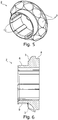
- Fig. 5
- eine Perspektivansicht des Aufschubrings und
- Fig. 6:
- eine Schnittansicht durch den Aufschubring.
- Fig. 1:
- a perspective view of a profile head with a postponed thereon,
- Fig. 2:
- a sectional view through the profile head with the postponed thereon,
- 3:
- a perspective view of the profile head,
- 4:
- a sectional view through the profile head,
- Fig. 5
- a perspective view of the pusher ring and
- Fig. 6:
- a sectional view through the slip ring.
In den
Auf den Vorsprung 4 des Profilkopfes 1 ist ein auch in den
Zur Montage wird der Aufschubring 2 auf den Vorsprung 4 des Profilkopfes 1 aufgeschoben, wobei die Federn 12 in die Nuten 11 eingreifen. Dabei wird der Aufschubring 2 mit der Aufschubhülse 6 in den ringförmigen Schlitz 7 eingeführt, bis die Stirnseite der Aufschubhülse 6 in Anlage mit dem Profilkopf 1 kommt. In dem aufgeschobenen Zustand bilden kalottenförmig ausgebildete Teilaufnahmen 3 an dem Profilkopf 1 und an dem Aufschubring 6 gemeinsam jeweils paarweise Aufnahmen mit einem Durchmesser 10 für Massekörper eines Gurtstraffers aus. Somit wird ein Strafferantriebsrad 16 zweiteilig von dem Profilkopf 1 und dem Aufschubring 2 ausgebildet.For mounting the push-on
Um den Aufschubring 2 auf dem Vorsprung 4 kraftschlüssig zu fixieren, werden die Verformungselemente 13 in Umfangsrichtung mit Kraft beaufschlagt und verformt. Es kann insbesondere auch vorgesehen sein, dass vor der Kraftbeaufschlagung ein nicht dargestellter Torsionsstab ins Innere des Vorsprunges 4 eingeführt wird, wobei die Verformungselemente 13 zusätzlich zu der Kraftbeaufschlagung in Umfangsrichtung radial nach innen mit Kraft beaufschlagt und verformt werden, so dass der Torsionsstab kraftschlüssig in den Vorsprung 4 festgelegt ist und mit dem Profilkopf 1 verbunden ist. Um eine möglichst sichere Verbindung zwischen dem Aufschubring 2 und dem Profilkopf 1 zu gewährleisten und eine große Lagerfläche zwischen Aufschubring 2 und Profilkopf 1 bereitzustellen, ist die Länge 9 der Aufschubhülse 6 größer als der Durchmesser 10 der durch die Teilaufnahmen 3 gebildeten Aufnahmen für die Massekörper.In order to force fit the push-on
In einem an einem Gurtaufroller montierten Zustand überlappt der an dem Aufschubring 2 ausgebildete Lagerring 8 mit einem radial außen angeordneten Wellenkörper, der zumindest im Belastungsfall durch den Lagerring 8 radial abgestützt wird.In a state mounted on a belt retractor, the
- 11
- Profilkopfprofile head
- 22
- Aufschubringpostponement ring
- 33
- Teilaufnahmepart seat
- 44
- Vorsprunghead Start
- 55
- Endbereichend
- 66
- Aufschubhülsepush-on sleeve
- 77
- Schlitzslot
- 88th
- Lagerringbearing ring
- 99
- Längelength
- 1010
- Durchmesserdiameter
- 1111
- Nutgroove
- 1212
- Federfeather
- 1313
- Verformungselementflexure
- 1414
- Zapfenspigot
- 1515
- BlockierklinkenaufnahmeBlocking latch receptacle
- 1616
- Strafferantriebsradtensioner
Claims (6)
- Belt retractor with a belt shaft comprising a shaft body, a profile head (1) and a torsion rod, wherein the torsion rod arranged in the shaft body is connected by a first end to the shaft body and by a second end to the profile head (1) and the profile head (1) can be blocked firmly on the vehicle, and with a belt tensioner, wherein a tensioning drive wheel (16) of the belt tensioner is directly connected in a non-rotating manner to the profile head (1) of the belt shaft, and wherein solid bodies can be placed in a force-transferring manner in engagement with the tensioning drive wheel (16) for driving the belt shaft in the winding-up direction, wherein the tensioning drive wheel (16) is formed in two parts from the profile head (1) of the belt shaft and from a push-on ring (2) pushed onto the profile head (1) and positively connected to the latter in a force-locking manner, wherein opposing, cup-shaped partial receptacles (3) are formed on the profile head (1) and on the push-on ring (2), characterized by that an axially projecting annular push-on casing (6) is formed on the push-on ring (2), which casing makes contact on a front-side surface with the profile head (1).
- Belt retractor according to Claim 1, wherein the profile head (1) of the belt shaft comprises an axially projecting, annular projection (4) which receives the torsion rod on the inside and the push-on ring (2) is completely pushed on the annular projection (4), wherein at least one end area (5) of the projection (4), which end area projects over the pushed-on push-on ring (2) is plastically deformed for the force-locking connection to the pushed-on push-on ring (2).
- The belt retractor according to one of the previous claims, wherein an annular slot (7) is formed on the profile head (1) into which an annular push-on casing (6), which projects axially and is formed on the push-on ring (2), is inserted.
- The belt retractor according to Claims 1 and 2 or 3, wherein the push-on casing (6) has a length (9) which is at least as great as a diameter (10) of a receptacle for a solid body, which receptacle is formed by two cup-shaped partial receptacles (3), and the push-on casing (6) rests over its entire length (9) inside on the projection (4).
- The belt retractor according to one of Claims 2 to 4, wherein grooves (11) which are axially aligned radially outside on the projection (4) and for receiving corresponding, axially running springs (12) are formed on the inner side of the push-on ring (2) and deformation elements (13) are formed on the front side on the projection (4) and are aligned with the grooves (11), which elements are plastically deformed for connecting the profile head (1) to the push-on ring (2) and to the second end of the torsion rod.
- The belt retractor according to one of the previous claims, wherein a bearing ring (8) for the shaft body is formed in one part on the push-on ring (2) on a side facing the shaft body, wherein the shaft body and the two-part tensioning drive wheel axially overlap in the area of the bearing ring (8).
Applications Claiming Priority (2)
| Application Number | Priority Date | Filing Date | Title |
|---|---|---|---|
| DE102014114140.7A DE102014114140B4 (en) | 2014-09-29 | 2014-09-29 | Belt retractor with two-part tensioner wheel |
| PCT/EP2015/072220 WO2016050675A1 (en) | 2014-09-29 | 2015-09-28 | Belt retractor with two-part tensioning drive wheel |
Publications (2)
| Publication Number | Publication Date |
|---|---|
| EP3201051A1 EP3201051A1 (en) | 2017-08-09 |
| EP3201051B1 true EP3201051B1 (en) | 2018-12-05 |
Family
ID=54252268
Family Applications (1)
| Application Number | Title | Priority Date | Filing Date |
|---|---|---|---|
| EP15775140.5A Active EP3201051B1 (en) | 2014-09-29 | 2015-09-28 | Belt retractor with two-part tensioning drive wheel |
Country Status (5)
| Country | Link |
|---|---|
| US (1) | US10343647B2 (en) |
| EP (1) | EP3201051B1 (en) |
| CN (1) | CN106715204B (en) |
| DE (1) | DE102014114140B4 (en) |
| WO (1) | WO2016050675A1 (en) |
Families Citing this family (3)
| Publication number | Priority date | Publication date | Assignee | Title |
|---|---|---|---|---|
| CN107571835B (en) * | 2016-07-05 | 2020-05-15 | 奥托立夫开发公司 | Transmission wheel and pre-tightening type safety belt retractor using same |
| DE102019211852B3 (en) * | 2019-08-07 | 2020-12-10 | Autoliv Development Ab | BELT ROLLER |
| CN111891873B (en) * | 2020-08-05 | 2022-01-25 | 鹤山扬阳智能机械装备有限公司 | Elevator brake assembly |
Family Cites Families (17)
| Publication number | Priority date | Publication date | Assignee | Title |
|---|---|---|---|---|
| DE19512660C2 (en) * | 1994-04-11 | 1999-11-18 | Autoliv Dev | Pyrotechnic rotary tensioner with mass body drive |
| WO1995027638A1 (en) | 1994-04-11 | 1995-10-19 | Autoliv Development Ab | Mass-body drive for a rotary tightening device |
| US5881962A (en) * | 1994-04-11 | 1999-03-16 | Autoliv Development Ab | Mass-body drive for a rotary tightening device |
| US5601251A (en) * | 1995-03-31 | 1997-02-11 | Trw Vehicle Safety Systems Inc. | Adjustable automatic locking retractor |
| GB2347124B (en) * | 1999-02-26 | 2003-02-05 | Takata Corp | Pre-tensioner |
| DE10213906B4 (en) * | 2002-03-28 | 2006-11-23 | Autoliv Development Ab | power tensioner |
| JP4166096B2 (en) * | 2003-01-31 | 2008-10-15 | 芦森工業株式会社 | Seat belt retractor |
| DE102008059386B3 (en) | 2008-11-27 | 2010-07-01 | Autoliv Development Ab | Belt retractor with a force limiting device |
| US20100176236A1 (en) * | 2009-01-09 | 2010-07-15 | Autoliv Asp, Inc. | High performance tightener |
| US8740125B2 (en) * | 2009-04-17 | 2014-06-03 | Autoliv Development Ab | Seatbelt retractor |
| US9114780B2 (en) * | 2009-10-30 | 2015-08-25 | Autoliv Development Ab | Pretensioner device for a seat belt |
| DE102010051418A1 (en) * | 2010-11-17 | 2012-05-24 | Trw Automotive Gmbh | Belt retractor for a safety belt system and method for assembling a belt retractor |
| DE102011008405B4 (en) * | 2011-01-12 | 2020-10-15 | Autoliv Development Ab | Belt retractor with a speed-controlled force limiting device |
| DE102012217261B4 (en) * | 2012-09-25 | 2018-10-11 | Autoliv Development Ab | Belt tensioner for a belt retractor |
| DE102013220949B4 (en) * | 2013-10-16 | 2021-07-08 | Autoliv Development Ab | Force limiting device for a seat belt system |
| US9555768B2 (en) * | 2014-05-23 | 2017-01-31 | Autoliv Asp, Inc. | Retractor pretensioner assembly |
| US9744940B1 (en) * | 2016-04-13 | 2017-08-29 | Autoliv Asp, Inc. | Seatbelt pretensioning retractor assembly |
-
2014
- 2014-09-29 DE DE102014114140.7A patent/DE102014114140B4/en active Active
-
2015
- 2015-09-28 EP EP15775140.5A patent/EP3201051B1/en active Active
- 2015-09-28 US US15/514,832 patent/US10343647B2/en active Active
- 2015-09-28 WO PCT/EP2015/072220 patent/WO2016050675A1/en active Application Filing
- 2015-09-28 CN CN201580052571.2A patent/CN106715204B/en active Active
Non-Patent Citations (1)
| Title |
|---|
| None * |
Also Published As
| Publication number | Publication date |
|---|---|
| CN106715204B (en) | 2020-02-14 |
| EP3201051A1 (en) | 2017-08-09 |
| US10343647B2 (en) | 2019-07-09 |
| DE102014114140B4 (en) | 2017-01-05 |
| CN106715204A (en) | 2017-05-24 |
| DE102014114140A1 (en) | 2016-03-31 |
| WO2016050675A1 (en) | 2016-04-07 |
| US20170313279A1 (en) | 2017-11-02 |
Similar Documents
| Publication | Publication Date | Title |
|---|---|---|
| DE102015219930B4 (en) | Freewheel device for a motor vehicle | |
| DE102014219256A1 (en) | Ball Screw | |
| EP3631219B1 (en) | Steering shaft for a motor vehicle | |
| EP3201051B1 (en) | Belt retractor with two-part tensioning drive wheel | |
| DE102008057222B4 (en) | bearing arrangement | |
| EP2615346B1 (en) | Spring belt clamp | |
| EP2867546A1 (en) | Snap ring | |
| DE102015209252B4 (en) | Tensioner drive for a seat belt device | |
| DE102007023972A1 (en) | Method for producing a hub in the pressing method by means of at least one rotatable spinning roller | |
| DE102008025266A1 (en) | Bearing arrangement and assembly process | |
| DE102006031525B4 (en) | bearing seat | |
| DE102013205690A1 (en) | Belt retractor with a force limiting device | |
| DE102012215395A1 (en) | Ball screw drive has spindle nut arranged on threaded spindle, where spindle nut has helical nut unit provided around spindle axis of twisted ball groove and common endless ball channel formed with the threaded spindle | |
| EP3568331B1 (en) | Steering shaft for a motor vehicle | |
| DE102018107765B3 (en) | Gear arrangement for a device for level adjustment of a vehicle body | |
| EP2395255B1 (en) | Releasable axial fixing of two components | |
| WO2021052527A1 (en) | Freewheel assembly having a deep-drawn flange | |
| EP2299138B1 (en) | Assembly unit for motor vehicle transmissions | |
| DE102009017137A1 (en) | Belt pretensioner for belt rewinder of motor vehicle, has gas generator housing formed from two parts that are connected with each other, where one of parts forms piston after releasing connection of two parts | |
| DE102018102577A1 (en) | coupling device | |
| DE102015222301B4 (en) | Roller freewheel | |
| DE102008020853A1 (en) | Roller bearing, particularly needle bearing for supporting steering shaft of vehicle, has outer ring forming outer rolling body raceway, and part integrally connected with outer ring | |
| DE10341434B4 (en) | Belt retractor with an axial securing device for a rolled shaft body | |
| DE10238101B4 (en) | circlip | |
| DE102022211798A1 (en) | Bearing pot set for a steering column and steering column with a bearing pot set |
Legal Events
| Date | Code | Title | Description |
|---|---|---|---|
| STAA | Information on the status of an ep patent application or granted ep patent |
Free format text: STATUS: THE INTERNATIONAL PUBLICATION HAS BEEN MADE |
|
| PUAI | Public reference made under article 153(3) epc to a published international application that has entered the european phase |
Free format text: ORIGINAL CODE: 0009012 |
|
| STAA | Information on the status of an ep patent application or granted ep patent |
Free format text: STATUS: REQUEST FOR EXAMINATION WAS MADE |
|
| 17P | Request for examination filed |
Effective date: 20170315 |
|
| AK | Designated contracting states |
Kind code of ref document: A1 Designated state(s): AL AT BE BG CH CY CZ DE DK EE ES FI FR GB GR HR HU IE IS IT LI LT LU LV MC MK MT NL NO PL PT RO RS SE SI SK SM TR |
|
| AX | Request for extension of the european patent |
Extension state: BA ME |
|
| RIN1 | Information on inventor provided before grant (corrected) |
Inventor name: WULFF, FRANK Inventor name: TRUEBNER, CLAUDIA Inventor name: KRAUS, JURI Inventor name: KUBBE, THOMAS Inventor name: SCHUBEL, KARSTEN |
|
| DAV | Request for validation of the european patent (deleted) | ||
| DAX | Request for extension of the european patent (deleted) | ||
| GRAP | Despatch of communication of intention to grant a patent |
Free format text: ORIGINAL CODE: EPIDOSNIGR1 |
|
| STAA | Information on the status of an ep patent application or granted ep patent |
Free format text: STATUS: GRANT OF PATENT IS INTENDED |
|
| INTG | Intention to grant announced |
Effective date: 20180627 |
|
| GRAS | Grant fee paid |
Free format text: ORIGINAL CODE: EPIDOSNIGR3 |
|
| GRAA | (expected) grant |
Free format text: ORIGINAL CODE: 0009210 |
|
| STAA | Information on the status of an ep patent application or granted ep patent |
Free format text: STATUS: THE PATENT HAS BEEN GRANTED |
|
| AK | Designated contracting states |
Kind code of ref document: B1 Designated state(s): AL AT BE BG CH CY CZ DE DK EE ES FI FR GB GR HR HU IE IS IT LI LT LU LV MC MK MT NL NO PL PT RO RS SE SI SK SM TR |
|
| REG | Reference to a national code |
Ref country code: GB Ref legal event code: FG4D Free format text: NOT ENGLISH |
|
| REG | Reference to a national code |
Ref country code: CH Ref legal event code: EP |
|
| REG | Reference to a national code |
Ref country code: AT Ref legal event code: REF Ref document number: 1072622 Country of ref document: AT Kind code of ref document: T Effective date: 20181215 |
|
| REG | Reference to a national code |
Ref country code: IE Ref legal event code: FG4D Free format text: LANGUAGE OF EP DOCUMENT: GERMAN |
|
| REG | Reference to a national code |
Ref country code: DE Ref legal event code: R096 Ref document number: 502015007136 Country of ref document: DE |
|
| REG | Reference to a national code |
Ref country code: NL Ref legal event code: MP Effective date: 20181205 |
|
| REG | Reference to a national code |
Ref country code: LT Ref legal event code: MG4D |
|
| PG25 | Lapsed in a contracting state [announced via postgrant information from national office to epo] |
Ref country code: BG Free format text: LAPSE BECAUSE OF FAILURE TO SUBMIT A TRANSLATION OF THE DESCRIPTION OR TO PAY THE FEE WITHIN THE PRESCRIBED TIME-LIMIT Effective date: 20190305 Ref country code: LT Free format text: LAPSE BECAUSE OF FAILURE TO SUBMIT A TRANSLATION OF THE DESCRIPTION OR TO PAY THE FEE WITHIN THE PRESCRIBED TIME-LIMIT Effective date: 20181205 Ref country code: FI Free format text: LAPSE BECAUSE OF FAILURE TO SUBMIT A TRANSLATION OF THE DESCRIPTION OR TO PAY THE FEE WITHIN THE PRESCRIBED TIME-LIMIT Effective date: 20181205 Ref country code: NO Free format text: LAPSE BECAUSE OF FAILURE TO SUBMIT A TRANSLATION OF THE DESCRIPTION OR TO PAY THE FEE WITHIN THE PRESCRIBED TIME-LIMIT Effective date: 20190305 Ref country code: ES Free format text: LAPSE BECAUSE OF FAILURE TO SUBMIT A TRANSLATION OF THE DESCRIPTION OR TO PAY THE FEE WITHIN THE PRESCRIBED TIME-LIMIT Effective date: 20181205 Ref country code: HR Free format text: LAPSE BECAUSE OF FAILURE TO SUBMIT A TRANSLATION OF THE DESCRIPTION OR TO PAY THE FEE WITHIN THE PRESCRIBED TIME-LIMIT Effective date: 20181205 Ref country code: LV Free format text: LAPSE BECAUSE OF FAILURE TO SUBMIT A TRANSLATION OF THE DESCRIPTION OR TO PAY THE FEE WITHIN THE PRESCRIBED TIME-LIMIT Effective date: 20181205 |
|
| PG25 | Lapsed in a contracting state [announced via postgrant information from national office to epo] |
Ref country code: AL Free format text: LAPSE BECAUSE OF FAILURE TO SUBMIT A TRANSLATION OF THE DESCRIPTION OR TO PAY THE FEE WITHIN THE PRESCRIBED TIME-LIMIT Effective date: 20181205 Ref country code: SE Free format text: LAPSE BECAUSE OF FAILURE TO SUBMIT A TRANSLATION OF THE DESCRIPTION OR TO PAY THE FEE WITHIN THE PRESCRIBED TIME-LIMIT Effective date: 20181205 Ref country code: RS Free format text: LAPSE BECAUSE OF FAILURE TO SUBMIT A TRANSLATION OF THE DESCRIPTION OR TO PAY THE FEE WITHIN THE PRESCRIBED TIME-LIMIT Effective date: 20181205 Ref country code: GR Free format text: LAPSE BECAUSE OF FAILURE TO SUBMIT A TRANSLATION OF THE DESCRIPTION OR TO PAY THE FEE WITHIN THE PRESCRIBED TIME-LIMIT Effective date: 20190306 |
|
| PG25 | Lapsed in a contracting state [announced via postgrant information from national office to epo] |
Ref country code: NL Free format text: LAPSE BECAUSE OF FAILURE TO SUBMIT A TRANSLATION OF THE DESCRIPTION OR TO PAY THE FEE WITHIN THE PRESCRIBED TIME-LIMIT Effective date: 20181205 |
|
| PG25 | Lapsed in a contracting state [announced via postgrant information from national office to epo] |
Ref country code: PL Free format text: LAPSE BECAUSE OF FAILURE TO SUBMIT A TRANSLATION OF THE DESCRIPTION OR TO PAY THE FEE WITHIN THE PRESCRIBED TIME-LIMIT Effective date: 20181205 Ref country code: CZ Free format text: LAPSE BECAUSE OF FAILURE TO SUBMIT A TRANSLATION OF THE DESCRIPTION OR TO PAY THE FEE WITHIN THE PRESCRIBED TIME-LIMIT Effective date: 20181205 Ref country code: IT Free format text: LAPSE BECAUSE OF FAILURE TO SUBMIT A TRANSLATION OF THE DESCRIPTION OR TO PAY THE FEE WITHIN THE PRESCRIBED TIME-LIMIT Effective date: 20181205 Ref country code: PT Free format text: LAPSE BECAUSE OF FAILURE TO SUBMIT A TRANSLATION OF THE DESCRIPTION OR TO PAY THE FEE WITHIN THE PRESCRIBED TIME-LIMIT Effective date: 20190405 |
|
| PG25 | Lapsed in a contracting state [announced via postgrant information from national office to epo] |
Ref country code: SM Free format text: LAPSE BECAUSE OF FAILURE TO SUBMIT A TRANSLATION OF THE DESCRIPTION OR TO PAY THE FEE WITHIN THE PRESCRIBED TIME-LIMIT Effective date: 20181205 Ref country code: EE Free format text: LAPSE BECAUSE OF FAILURE TO SUBMIT A TRANSLATION OF THE DESCRIPTION OR TO PAY THE FEE WITHIN THE PRESCRIBED TIME-LIMIT Effective date: 20181205 Ref country code: RO Free format text: LAPSE BECAUSE OF FAILURE TO SUBMIT A TRANSLATION OF THE DESCRIPTION OR TO PAY THE FEE WITHIN THE PRESCRIBED TIME-LIMIT Effective date: 20181205 Ref country code: IS Free format text: LAPSE BECAUSE OF FAILURE TO SUBMIT A TRANSLATION OF THE DESCRIPTION OR TO PAY THE FEE WITHIN THE PRESCRIBED TIME-LIMIT Effective date: 20190405 Ref country code: SK Free format text: LAPSE BECAUSE OF FAILURE TO SUBMIT A TRANSLATION OF THE DESCRIPTION OR TO PAY THE FEE WITHIN THE PRESCRIBED TIME-LIMIT Effective date: 20181205 |
|
| REG | Reference to a national code |
Ref country code: DE Ref legal event code: R097 Ref document number: 502015007136 Country of ref document: DE |
|
| PLBE | No opposition filed within time limit |
Free format text: ORIGINAL CODE: 0009261 |
|
| STAA | Information on the status of an ep patent application or granted ep patent |
Free format text: STATUS: NO OPPOSITION FILED WITHIN TIME LIMIT |
|
| PG25 | Lapsed in a contracting state [announced via postgrant information from national office to epo] |
Ref country code: DK Free format text: LAPSE BECAUSE OF FAILURE TO SUBMIT A TRANSLATION OF THE DESCRIPTION OR TO PAY THE FEE WITHIN THE PRESCRIBED TIME-LIMIT Effective date: 20181205 Ref country code: SI Free format text: LAPSE BECAUSE OF FAILURE TO SUBMIT A TRANSLATION OF THE DESCRIPTION OR TO PAY THE FEE WITHIN THE PRESCRIBED TIME-LIMIT Effective date: 20181205 |
|
| 26N | No opposition filed |
Effective date: 20190906 |
|
| PG25 | Lapsed in a contracting state [announced via postgrant information from national office to epo] |
Ref country code: TR Free format text: LAPSE BECAUSE OF FAILURE TO SUBMIT A TRANSLATION OF THE DESCRIPTION OR TO PAY THE FEE WITHIN THE PRESCRIBED TIME-LIMIT Effective date: 20181205 |
|
| PG25 | Lapsed in a contracting state [announced via postgrant information from national office to epo] |
Ref country code: MC Free format text: LAPSE BECAUSE OF FAILURE TO SUBMIT A TRANSLATION OF THE DESCRIPTION OR TO PAY THE FEE WITHIN THE PRESCRIBED TIME-LIMIT Effective date: 20181205 |
|
| REG | Reference to a national code |
Ref country code: CH Ref legal event code: PL |
|
| PG25 | Lapsed in a contracting state [announced via postgrant information from national office to epo] |
Ref country code: LU Free format text: LAPSE BECAUSE OF NON-PAYMENT OF DUE FEES Effective date: 20190928 Ref country code: IE Free format text: LAPSE BECAUSE OF NON-PAYMENT OF DUE FEES Effective date: 20190928 Ref country code: CH Free format text: LAPSE BECAUSE OF NON-PAYMENT OF DUE FEES Effective date: 20190930 Ref country code: LI Free format text: LAPSE BECAUSE OF NON-PAYMENT OF DUE FEES Effective date: 20190930 |
|
| REG | Reference to a national code |
Ref country code: BE Ref legal event code: MM Effective date: 20190930 |
|
| PG25 | Lapsed in a contracting state [announced via postgrant information from national office to epo] |
Ref country code: BE Free format text: LAPSE BECAUSE OF NON-PAYMENT OF DUE FEES Effective date: 20190930 |
|
| PG25 | Lapsed in a contracting state [announced via postgrant information from national office to epo] |
Ref country code: CY Free format text: LAPSE BECAUSE OF FAILURE TO SUBMIT A TRANSLATION OF THE DESCRIPTION OR TO PAY THE FEE WITHIN THE PRESCRIBED TIME-LIMIT Effective date: 20181205 |
|
| PG25 | Lapsed in a contracting state [announced via postgrant information from national office to epo] |
Ref country code: MT Free format text: LAPSE BECAUSE OF FAILURE TO SUBMIT A TRANSLATION OF THE DESCRIPTION OR TO PAY THE FEE WITHIN THE PRESCRIBED TIME-LIMIT Effective date: 20181205 Ref country code: HU Free format text: LAPSE BECAUSE OF FAILURE TO SUBMIT A TRANSLATION OF THE DESCRIPTION OR TO PAY THE FEE WITHIN THE PRESCRIBED TIME-LIMIT; INVALID AB INITIO Effective date: 20150928 |
|
| REG | Reference to a national code |
Ref country code: AT Ref legal event code: MM01 Ref document number: 1072622 Country of ref document: AT Kind code of ref document: T Effective date: 20200928 |
|
| PG25 | Lapsed in a contracting state [announced via postgrant information from national office to epo] |
Ref country code: AT Free format text: LAPSE BECAUSE OF NON-PAYMENT OF DUE FEES Effective date: 20200928 |
|
| PG25 | Lapsed in a contracting state [announced via postgrant information from national office to epo] |
Ref country code: MK Free format text: LAPSE BECAUSE OF FAILURE TO SUBMIT A TRANSLATION OF THE DESCRIPTION OR TO PAY THE FEE WITHIN THE PRESCRIBED TIME-LIMIT Effective date: 20181205 |
|
| PGFP | Annual fee paid to national office [announced via postgrant information from national office to epo] |
Ref country code: GB Payment date: 20220927 Year of fee payment: 8 |
|
| P01 | Opt-out of the competence of the unified patent court (upc) registered |
Effective date: 20230507 |
|
| PGFP | Annual fee paid to national office [announced via postgrant information from national office to epo] |
Ref country code: FR Payment date: 20230926 Year of fee payment: 9 Ref country code: DE Payment date: 20230928 Year of fee payment: 9 |