EP3200326B1 - Antriebsstrangmodul für ein kraftfahrzeug - Google Patents
Antriebsstrangmodul für ein kraftfahrzeug Download PDFInfo
- Publication number
- EP3200326B1 EP3200326B1 EP16205061.1A EP16205061A EP3200326B1 EP 3200326 B1 EP3200326 B1 EP 3200326B1 EP 16205061 A EP16205061 A EP 16205061A EP 3200326 B1 EP3200326 B1 EP 3200326B1
- Authority
- EP
- European Patent Office
- Prior art keywords
- flywheel
- rotor
- fastening
- module according
- fastening points
- Prior art date
- Legal status (The legal status is an assumption and is not a legal conclusion. Google has not performed a legal analysis and makes no representation as to the accuracy of the status listed.)
- Active
Links
Images


Classifications
-
- H—ELECTRICITY
- H02—GENERATION; CONVERSION OR DISTRIBUTION OF ELECTRIC POWER
- H02K—DYNAMO-ELECTRIC MACHINES
- H02K7/00—Arrangements for handling mechanical energy structurally associated with dynamo-electric machines, e.g. structural association with mechanical driving motors or auxiliary dynamo-electric machines
- H02K7/003—Couplings; Details of shafts
-
- F—MECHANICAL ENGINEERING; LIGHTING; HEATING; WEAPONS; BLASTING
- F16—ENGINEERING ELEMENTS AND UNITS; GENERAL MEASURES FOR PRODUCING AND MAINTAINING EFFECTIVE FUNCTIONING OF MACHINES OR INSTALLATIONS; THERMAL INSULATION IN GENERAL
- F16F—SPRINGS; SHOCK-ABSORBERS; MEANS FOR DAMPING VIBRATION
- F16F15/00—Suppression of vibrations in systems; Means or arrangements for avoiding or reducing out-of-balance forces, e.g. due to motion
- F16F15/30—Flywheels
- F16F15/315—Flywheels characterised by their supporting arrangement, e.g. mountings, cages, securing inertia member to shaft
- F16F15/3153—Securing inertia members to the shafts
-
- H—ELECTRICITY
- H02—GENERATION; CONVERSION OR DISTRIBUTION OF ELECTRIC POWER
- H02K—DYNAMO-ELECTRIC MACHINES
- H02K7/00—Arrangements for handling mechanical energy structurally associated with dynamo-electric machines, e.g. structural association with mechanical driving motors or auxiliary dynamo-electric machines
- H02K7/006—Structural association of a motor or generator with the drive train of a motor vehicle
-
- F—MECHANICAL ENGINEERING; LIGHTING; HEATING; WEAPONS; BLASTING
- F16—ENGINEERING ELEMENTS AND UNITS; GENERAL MEASURES FOR PRODUCING AND MAINTAINING EFFECTIVE FUNCTIONING OF MACHINES OR INSTALLATIONS; THERMAL INSULATION IN GENERAL
- F16F—SPRINGS; SHOCK-ABSORBERS; MEANS FOR DAMPING VIBRATION
- F16F15/00—Suppression of vibrations in systems; Means or arrangements for avoiding or reducing out-of-balance forces, e.g. due to motion
- F16F15/30—Flywheels
-
- H—ELECTRICITY
- H02—GENERATION; CONVERSION OR DISTRIBUTION OF ELECTRIC POWER
- H02K—DYNAMO-ELECTRIC MACHINES
- H02K7/00—Arrangements for handling mechanical energy structurally associated with dynamo-electric machines, e.g. structural association with mechanical driving motors or auxiliary dynamo-electric machines
- H02K7/02—Additional mass for increasing inertia, e.g. flywheels
-
- H—ELECTRICITY
- H02—GENERATION; CONVERSION OR DISTRIBUTION OF ELECTRIC POWER
- H02K—DYNAMO-ELECTRIC MACHINES
- H02K7/00—Arrangements for handling mechanical energy structurally associated with dynamo-electric machines, e.g. structural association with mechanical driving motors or auxiliary dynamo-electric machines
- H02K7/14—Structural association with mechanical loads, e.g. with hand-held machine tools or fans
-
- H—ELECTRICITY
- H02—GENERATION; CONVERSION OR DISTRIBUTION OF ELECTRIC POWER
- H02K—DYNAMO-ELECTRIC MACHINES
- H02K7/00—Arrangements for handling mechanical energy structurally associated with dynamo-electric machines, e.g. structural association with mechanical driving motors or auxiliary dynamo-electric machines
- H02K7/18—Structural association of electric generators with mechanical driving motors, e.g. with turbines
- H02K7/1807—Rotary generators
- H02K7/1815—Rotary generators structurally associated with reciprocating piston engines
Definitions
- the present invention relates to a drive train module for a motor vehicle.
- a drive train module with a flywheel and a crankshaft starter generator and a corresponding motor vehicle are described.
- the laid-open specification discloses DE 32 27 810 A1 an electrical machine integrated into the clutch, consisting of a stator mounted in the clutch housing and a rotor in the form of a squirrel cage attached to the rotating clutch housing.
- a similar device is also from the patent application US 2002/0033605 A1 known.
- a flywheel arranged in the drive train is designed as a rotor in order to enable the crankshaft to be turned by an electric motor.
- the document US 2014/015354 A1 discloses a generator motor that includes a rotor core and a flywheel.
- a closing element in the form of a sensor plate is fixed to an axial end face of the rotor core by means of fastening screws which are inserted in the rotor core.
- the electric machine arranged in the drive train can also be used as a generator in order to generate electrical energy from the kinetic energy of the crankshaft driven by an internal combustion engine.
- the EP 1 669 287 A1 a generator device with a rotor in the form of a magnetic component that can be connected non-rotatably to the crankshaft.
- the power generation can take place in continuous operation, as in the case just mentioned, or as in the U.S. 5,172,006 A provided only in certain driving situations, for example in order to recuperate energy during braking by the crankshaft, which is decoupled from the internal combustion engine, driving the crankshaft starter generator.
- the crankshaft starter generator can serve as a generator replacement when driving.
- FIG 1A shows a section in the upper half of the figure and a view of a conventional drive train module 10 for a motor vehicle in the lower half of the figure.
- the image plane is parallel to an axis of rotation 1 of a crankshaft.
- the conventional drive train module 10 comprises a flywheel 2 connected to the crankshaft and a rotor 4 which rests in a frictionally locking manner on a web 3 formed on the flywheel 2.
- a lateral surface of the web 3 forms a press fit 5, onto which a radially inner fitting 6 of the rotor 4 is pressed, as in the perspective illustration of FIG Figure 1B shown. Therefore, an axial length of the web 3 must at least correspond to the axial length of the rotor 4.
- the exploded view of the Figure 1C shows flywheel 3 and rotor 4 with an exposed press fit 5 or fit 6.
- Flywheel 2 comprises a starter ring gear 8.
- the disadvantage here is that the flywheel must have an additional connection surface which is at least as long as the rotor.
- the task is therefore to reduce the moment of inertia caused by the crankshaft starter generator.
- a drive train module for a motor vehicle is provided with the features of the main claim.
- Advantageous designs and applications are the subject matter of the dependent claims and are explained in more detail below with partial reference to the figures.
- the drive train module comprises a flywheel connected or connectable to a crankshaft and a crankshaft starter generator.
- the flywheel has a large number of attachment points.
- the crankshaft starter generator includes a rotor. In an area of the rotor with soft magnetic effect, a multiplicity of through openings are arranged in each case in spatial association with the fastening points of the flywheel. Through the through openings, pin-shaped fastening elements act together with the respectively assigned fastening points for the rotationally fixed connection of the rotor and flywheel.
- Embodiments of the drive train module can reduce the moment of inertia for a rotation of the crankshaft compared to conventional connection techniques by directly connecting the flywheel and the magnetically active rotor area.
- the rotor can be connected non-rotatably to the crankshaft via the flywheel. A direct coupling of the rotor to the crankshaft can be dispensed with.
- the rotor can be supported by the non-rotatable connection together with the flywheel. There is no need for the rotor to have its own rotary bearing.
- the rotor can be closed in a ring.
- the rotor can be closed circumferentially around the axis of rotation of the crankshaft.
- the rotor can be arranged around the axis of rotation of the crankshaft without cutting it.
- a radially inner surface of the rotor can deviate from a circular cylinder jacket surface. There is no need for a fit on the radially inner surface.
- the flywheel can have through recesses.
- the moment of inertia can be further reduced and / or a further function, for example that of a fan wheel or an assembly access, can be achieved.
- the soft magnetically effective area can be an electrically inducible and / or magnetodynamically effective area.
- the rotor for example the area of the rotor which is effective magnetically, can have a laminate of ferromagnetic layers.
- the laminate of ferromagnetic layers can be designed to suppress eddy currents, at least perpendicular to the layers.
- the through openings can traverse the layers.
- the through openings of the rotor can each be perpendicular to a plane of rotation of the flywheel and / or parallel to an axis of rotation of the crankshaft.
- the layers can be parallel to one another.
- the layers can be arranged perpendicular to the axis of rotation of the crankshaft.
- the through openings can be perpendicular to the layers.
- the ferromagnetic layers can be soft magnetic.
- the ferromagnetic layers can be formed by non-grain-oriented sheet metal.
- the laminate of ferromagnetic layers can be formed by a laminated core.
- the layers can be electrically isolated from one another.
- the ferromagnetic layers can be isolated on their surface by phosphating layers.
- the fastening elements can be electrically insulated from the layers. By isolating the fastening elements, a short circuit of the layers and / or eddy currents through adjacent fastening elements can be suppressed.
- the fastening elements can be isolated from the layers by a gap (for example an air gap) in the through opening.
- insulating sleeves for example made of plastic
- the pin-shaped fastening elements can each be arranged in one of the through openings.
- An internal thread can be provided at each of the fastening points.
- the fastening elements can comprise screws or threaded bolts.
- An external thread at an end of the fastening element (first end) facing the associated fastening point can be in engagement with the internal thread.
- An end of the fastening element facing away from the assigned fastening point (second end) can have a screw head or an external thread engaging with a nut.
- a plate spring can be arranged between a closing element and the screw head or the nut.
- the first end can be with be welded to the flywheel and / or the second end to the rotor.
- the fastening elements can comprise rivets.
- the fastening points can be formed on projections.
- the flywheel can have projections that are spaced apart from one another.
- the projections can extend parallel to the axis of rotation of the crankshaft.
- Each projection can form one or more fastening points.
- a contact surface for the rotor can be present on each projection and / or a threaded hole can be made for the internal thread.
- the protrusions can also be referred to as slugs.
- the drive train module comprises a terminating element, the terminating element being arranged between the rotor and the end of the fastening element facing away from the respective fastening point.
- the closing element comprises separate segments, e.g. B. ring segments. Each segment of the closing element is assigned to a fastening point.
- the closing element rests flat against a side surface of the area of the rotor which is active in soft magnetic fields and which faces away from the flywheel.
- the side surface of the rotor facing away from the flywheel can be perpendicular to the axis of rotation of the crankshaft.
- the closing element covers the side face of the rotor facing away from the flywheel, in that a profile of the closing element is congruent with the side face in a view in the direction of the axis of rotation.
- the closure element has machine-readable (or sensor-readable) markings.
- the markings can be arranged on a circumference of the closing element.
- the markings are designed to detect a rotary movement and / or a rotary position of the closing element (or of the crankshaft connected to it in a rotationally fixed manner).
- the markings can be detected optically, for example by reflection or transmission.
- the markings can be formed by recesses and / or a circumferential toothing.
- the markings can comprise a multiplicity of circumferentially equidistant markings.
- the multitude of circumferentially equidistant markings can enable the detection of several angular velocities within one revolution.
- two adjacent markings can have a distance that is different from the distance between other adjacent markings.
- the distance between the two adjacent markings can be twice as great as the distance between all the other adjacent markings.
- the different distances between adjacent markings can enable the rotational position to be detected.
- the fastening points can be arranged on a side surface of the flywheel that is perpendicular to the axis of rotation of the crankshaft.
- the attachment points can be circumferential, for. B. equidistant, be arranged on the flywheel.
- the fastening points can be arranged on a first pitch circle of the flywheel.
- the fastening points can have contact surfaces.
- the rotor for example the laminated core, can rest on the contact surfaces.
- the contact surfaces of the multiplicity of fastening points can lie in a common first plane.
- the first plane can be parallel to the plane of rotation of the flywheel and / or perpendicular to the axis of rotation of the crankshaft.
- Further fastening points can be arranged on the same side surface and / or an opposite side surface of the flywheel.
- the fastening points for the rotor can be different from the other fastening points in terms of pitch circle radius and / or axial length.
- the other fastening points of the flywheel can thus be accessible even when the rotor is fastened.
- the further fastening points can be arranged on a second pitch circle.
- the radius of the first pitch circle can be different from the radius of the second pitch circle.
- the attachment points for the rotor can be formed in first projections of the flywheel.
- the further fastening points can be formed in second projections of the flywheel.
- a first axial length of the first projections can be different from a second axial length of the second projections.
- the further fastening points can have further contact surfaces. The other contact surfaces can lie in a second level.
- the second plane can be parallel and offset to the first plane.
- the axial lengths can be defined parallel to the axis of rotation of the crankshaft with respect to a plane of rotation of the flywheel.
- the further fastening points can be designed for a non-rotatable connection with a coupling or a transmission.
- recesses in particular round recesses, can be provided in the flywheel. These improve the tool accessibility in order to be able to screw on a gear.
- a motor vehicle in particular a commercial vehicle, is provided, the drive train of which comprises a drive train module according to the above aspect in one of the embodiment variants.
- Figure 2 Figure 3 is an exploded view of an example of a powertrain module, generally designated by reference numeral 100, for a motor vehicle.
- the module 100 comprises a flywheel 102 and a rotor 104 for a crankshaft starter generator.
- the flywheel 102 of the drive train module 100 can be connected to a crankshaft.
- An axis of rotation of the crankshaft is denoted by reference numeral 101.
- the flywheel 102 has a multiplicity of attachment points 112.
- through-openings 114 are provided in spatial association with the fastening points 112.
- Fastening elements 106 are arranged in the through openings 114.
- the fastening elements 106 are each connected to the flywheel 102 at a first end facing the assigned connection point 112.
- the pin-shaped fastening elements 106 transmit an axial tensile stress to a side surface 116 of the rotor 104 facing away from the flywheel 102.
- the tensile stress keeps the rotor 104 in contact with the flywheel 102, whereby the rotor 104 is rotationally fixed to the flywheel 102 connected is.
- the non-rotatable connection can be achieved by a force fit due to the tensile stress of the fastening elements 106.
- the pin-shaped fastening elements 106 anchored in the flywheel 102 can be arranged in a form-fitting manner in the through openings 114, for example by clamping the pin-shaped connecting elements 106 in the through openings 114.
- exemplary embodiments can be designed in this way be that an additional mass of the fastening elements 106 is almost equal to the mass reduction on the rotor 104 due to the through openings 114. In other words: the non-rotatable connection can be carried out with almost no contribution to the moment of inertia.
- the drivetrain module 100 optionally includes a ring gear 108 in which the pinion of an engagement starter engages.
- the engagement starter is preferably used for a cold start of the internal combustion engine, while an automatic start-stop system uses the crankshaft starter generator at the end of a stationary phase of the motor vehicle.
- the crankshaft starter generator can only be connected to a short-term memory, for example to feed the automatic start-stop system and / or to feed the on-board electrical system when the engine is switched off, with energy recuperated from braking processes and stored in the short-term memory. Without the engagement starter fed from a long-term memory (for example a lead accumulator), the short-term memory would have to be precharged from the long-term memory for the cold start.
- a long-term memory for example a lead accumulator
- crankshaft starter generator can be designed for a lower mechanical power by the additional engagement starter. As a result, the moment of inertia caused by the crankshaft starter generator can also be reduced.
- the drive train module 100 comprises a terminating element 110 on the transmission side.
- the terminating element 110 is arranged between the second end of the fastening elements 106 facing away from the flywheel 102 and the rotor 104.
- the second ends of the fastening elements 106 rest on the closing element 110 and transfer the tensile stress to the closing element 110.
- a wall thickness and / or a hardness of the closing element 110 is determined in such a way that the selective force transmission of the fastening elements 106 as a uniform contact pressure on the one facing away from the flywheel 102 Side surface 116 of the rotor 104 is distributed.
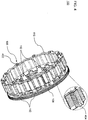
- FIG 3 is a perspective view of an embodiment of the flywheel 102.
- Each of the fastening points 112 is formed in each case on a projection 302, which extends parallel to the axis of rotation 101 from the flywheel 102.
- the projection 302 ends with a contact surface 304 perpendicular to the axis of rotation 101.
- a threaded bore with an internal thread 306 parallel to the axis of rotation 101 is made in the contact surface 304.
- the rotor 104 can be arranged at a sufficient distance from the flywheel 102 in order to interact with a stator.
- the moment of inertia caused by the circumferential mass of a conventional web 3 is reduced by the mass of the projections 302 located at the connection points 112.
- FIG. 13 shows a perspective illustration of the first example of the rotor 104 connected to the flywheel 102 by means of the fastening elements 106.
- screws serve as fastening elements 106, each with a screw head 402 at the second end of the fastening elements 106 facing away from the flywheel 102.
- a tightening torque of the screws determines their tensile stress and thus the contact pressure.
- At least the magnetically effective area of the rotor 104 is preferably made up of ferromagnetic layers 404, which are electrically insulated from one another by non-conductive intermediate layers to suppress eddy current losses.
- the ferromagnetic layers 404 are adhesively connected by the intermediate layers to form a laminate of ferromagnetic layers 404.
- An example of the laminate of ferromagnetic layers 404 is a laminated core, the soft magnetic layers of which are made from dynamo sheet.
- the layers 404 are not connected by the intermediate layers and are connected in a force-locking manner by the tensile stress of the fastening elements 106.
- the rotor 104 made up of ferromagnetic layers 404 is advantageously connected to the flywheel 102 using the closing element 110.
- the uniform contact pressure of the closing element 110 prevents the frictionally connected layers 404 from bending open or the adhesively connected layers 404 between adjacent fastening elements 106 from breaking open, for example after the screws have been tightened.
- the layers 404 or at least a first of the layers 404 can be designed with a sufficient wall thickness and / or the connection of the layers 404 with sufficient strength, so that the closing element 110 can be dispensed with.
- the individual ferromagnetic layers 404 of the rotor 104 can be separated from sheet metal rolls by punching. Due to the direct connection of flywheel 102 and rotor 104, there is no additional effort in the production of the layers 404 of the rotor 104, since the additional holes in the individual layers (to form the through openings 114) can be inserted in the same punching process. Since there is no need for a fit 6 on the radially inner surface of the rotor 104, the manufacture of the rotor 104 is simplified compared to the conventional rotor 4. For example, since the fit 6 is omitted, tolerances in the manufacture of the layers 404 can be widened. This results in less material scrap. Furthermore, a punching tool can be used for more punching processes until it has to be changed due to wear.
- a larger area of the flywheel 102 is accessible on the transmission side as a connection interface for further components, for example for a transmission adapter.
- the in Figure 3 The exemplary embodiment shown of the flywheel 102 has further fastening points 310.
- Each of the further fastening points 310 is formed by a separate further projection 312 which terminates with a further contact surface 314 perpendicular to the axis of rotation 101.
- a threaded bore parallel to the axis of rotation 101 with a further internal thread 316 is made in the further contact surface 314.
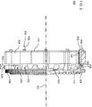
- Figure 5 shows in the upper half of the figure a radial partial section, parallel to the axis of rotation 101, of the first example of the drive train module 100.
- the corresponding view of the drive train module 100 is shown in the lower half of the figure.
- a first axial length 502 of the projections 302 for the rotor 104 is greater than a second axial length 504 of the further projections 312.
- the connection interface formed by the further fastening points 310 lies in its own plane between the flywheel 102 and the rotor 104.
- the transmission adapter of the transmission connected to the further fastening points 310 is arranged completely in the interior of the rotor 104.
- connection interfaces formed by the further fastening points 310 differ from the connection interface for the rotor 104 with regard to a pitch circle diameter of the fastening points 112 and the further fastening points 310.
- FIG. 13 shows a view of the drive train module 100 on the transmission side.
- the image plane of FIG Figure 6 is perpendicular to the axis of rotation 101 of the crankshaft.
- the fastening points 112 are arranged equidistantly on a first pitch circle 602.
- the further fastening points 310 are arranged equidistantly on a second pitch circle 604.
- a first pitch circle diameter of the first pitch circle 602 is larger than a second pitch circle diameter of the second pitch circle 604.
- a profile of the closing element 110 in the view in the direction of the axis of rotation 101 is, according to the invention, congruent with the side surface 116, i. H. with a profile of the rotor 104 in the view on the transmission side in the direction of the axis of rotation 101.
- the uniform contact pressure can be achieved with minimal use of mass.
- the fastening points 112 and the further fastening points 310 are preferably arranged alternately around the circumference, so that a further fastening point 310 is arranged between each two adjacent fastening points 112.
- the profile of the rotor 104 and the closing element 110 deviates from a circular line at the further fastening points 310 to form recesses 606.
- the further contact surfaces 314 of the further fastening points 310 are accessible on the transmission side through the recesses 606.
- the crankshaft is on one in the Figures 3 and 5
- the hub 320 shown can be screwed to the flywheel 102.
- Round through recesses 322 and 324 in the flywheel 102 are made on pitch circles outside the hub 320 and are used for tool accessibility, for example to screw a gear to the flywheel 102.
- the through recesses 322 and 324 contribute to a further reduction in the moment of inertia.
- the flywheel 102 optionally has further through recesses 330 for reducing the moment of inertia.
- a circumferential or substantially circumferential surface 326 protrudes from the flywheel 102 in the axial direction.
- the surface 326 enables a component attached to the flywheel, for example a transmission adapter, to be centered.
- the ring gear 108 is on an in Figure 3 Press fit 340 shown frictionally attached.
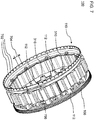
- Figure 7 shows a further example of the drive train module 100. Corresponding features are denoted by the same reference symbols. Their description and optional configuration in connection with the first exemplary embodiment apply accordingly to the second exemplary embodiment.
- markings 702 are attached to a circumferential ring, which are detected in a contactless manner by a speed sensor.
- the markings are recesses in a cylinder wall.
- the tachometer includes a fork light barrier, the radial light path of which is interrupted by the cylinder wall.
- the markings 702 encode both the rotational speed and the rotational position of the closing element 110 (and all components of the drive train module 100 connected to it in a rotationally fixed manner).
- adjacent markings 702 are arranged at a uniform first circumferential distance 704. Only a pair of adjacent markings 702 are arranged at a second circumferential spacing 706 that deviates from the first circumferential spacing 704.
- the second circumferential distance 706 is at least twice as large as the first circumferential distance 704.
- the second circumferential distance 706 is not an integral multiple of the first circumferential distance 704, so that the occurrence of the second circumferential distance 706 can be distinguished from an erroneously missing signal.
- the rotational speed (or angular velocity) can be detected with a time resolution that is a fraction of a period of rotation.
- the rotational position can be clearly determined when a signal sequence corresponding to the second circumferential distance 706 occurs.
- FIG 8 shows a section of a drive train component 800 parallel to the axis of rotation 101.
- the drive train component 800 comprises the rotating drive train module 100.
- the rotating drive train module 100 and a stator 802 are arranged in a housing.
- Stator coils 804 of the stator 802 are arranged around the rotor 104 outside the rotor 104.
- the housing includes a stator housing part 806 and a flywheel housing part 808.
- the rotor 104 In generator mode, the rotor 104 induces a voltage in the stator coils 804. A current driven by the voltage charges a short-term storage device. In the starter mode, the short-term memory feeds a current into the stator coils 804, the magnetic field of which magnetizes the area of the rotor 104 that is effective in soft magnetic fields and generates a torque.
- the weight and the moment of inertia can be reduced. Machining of the flywheel can be simplified because there is no press-fit surface.
- closing element makes it possible to integrate additional functionalities.
- Further interfaces can be integrated on the flywheel, in particular in the area of the connection to the rotor, for example for a compact design.
- the manufacture of the rotor can be simplified since the fit is no longer necessary.
Landscapes
- Engineering & Computer Science (AREA)
- General Engineering & Computer Science (AREA)
- Power Engineering (AREA)
- Physics & Mathematics (AREA)
- Acoustics & Sound (AREA)
- Aviation & Aerospace Engineering (AREA)
- Mechanical Engineering (AREA)
- Connection Of Motors, Electrical Generators, Mechanical Devices, And The Like (AREA)
Priority Applications (1)
| Application Number | Priority Date | Filing Date | Title |
|---|---|---|---|
| PL16205061T PL3200326T3 (pl) | 2016-01-26 | 2016-12-19 | Moduł układu przeniesienia napędu dla pojazdu mechanicznego |
Applications Claiming Priority (1)
| Application Number | Priority Date | Filing Date | Title |
|---|---|---|---|
| DE102016000835.0A DE102016000835A1 (de) | 2016-01-26 | 2016-01-26 | Antriebsstrangmodul für ein Kraftfahrzeug |
Publications (2)
| Publication Number | Publication Date |
|---|---|
| EP3200326A1 EP3200326A1 (de) | 2017-08-02 |
| EP3200326B1 true EP3200326B1 (de) | 2021-05-26 |
Family
ID=57629325
Family Applications (1)
| Application Number | Title | Priority Date | Filing Date |
|---|---|---|---|
| EP16205061.1A Active EP3200326B1 (de) | 2016-01-26 | 2016-12-19 | Antriebsstrangmodul für ein kraftfahrzeug |
Country Status (6)
| Country | Link |
|---|---|
| US (1) | US10578190B2 (pl) |
| EP (1) | EP3200326B1 (pl) |
| CN (1) | CN107026532B (pl) |
| DE (1) | DE102016000835A1 (pl) |
| HU (1) | HUE055253T2 (pl) |
| PL (1) | PL3200326T3 (pl) |
Families Citing this family (2)
| Publication number | Priority date | Publication date | Assignee | Title |
|---|---|---|---|---|
| JP7449953B2 (ja) * | 2019-02-11 | 2024-03-14 | アンバー キネティクス,インコーポレイテッド | 積層薄板ロータ |
| CN115405417A (zh) * | 2022-09-30 | 2022-11-29 | 重庆安来动力机械有限公司 | 集成飞轮结构 |
Citations (2)
| Publication number | Priority date | Publication date | Assignee | Title |
|---|---|---|---|---|
| JPH0730584U (ja) * | 1993-11-19 | 1995-06-06 | 株式会社三協精機製作所 | 周波数信号検出装置付きモータ |
| US20140015354A1 (en) * | 2011-03-31 | 2014-01-16 | Komatsu Ltd. | Generator motor cooling structure and generator motor |
Family Cites Families (18)
| Publication number | Priority date | Publication date | Assignee | Title |
|---|---|---|---|---|
| US633857A (en) * | 1899-04-14 | 1899-09-26 | Westinghouse Electric & Mfg Co | Dynamo-electric generator. |
| DE1093000B (de) * | 1956-03-23 | 1960-11-17 | Wipac Dev Ltd | Schwungradlaeufer fuer elektrische Stromerzeuger mit mehreren Dauermagneten |
| US4227108A (en) * | 1978-04-24 | 1980-10-07 | Tokyo Shibaura Electric Co., Ltd. | Glass compound layer for mechanical and thermal protection of a laminated iron core rotary electromachine |
| US4361953A (en) * | 1978-10-31 | 1982-12-07 | Emerson Electric Co. | Method of securing end shields to the stator assembly of a dynamoelectric machine |
| DE3037793A1 (de) | 1980-10-07 | 1982-05-13 | Robert Bosch Gmbh, 7000 Stuttgart | Elektrische maschine |
| DE3227810A1 (de) * | 1982-07-24 | 1984-01-26 | Bosch Gmbh Robert | Integrierte elektrische maschine fuer fahrzeug-hybrid-antrieb |
| WO1988006107A1 (fr) * | 1987-02-18 | 1988-08-25 | Hino Jidosha Kogyo Kabushiki Kaisha | Dispositif electrique de freinage et d'acceleration auxilaire pour vehicules automobiles |
| JPH02252970A (ja) * | 1989-03-27 | 1990-10-11 | Sawafuji Electric Co Ltd | スタータのロータおよびその製造方法 |
| DE19838038A1 (de) * | 1998-08-21 | 2000-02-24 | Bosch Gmbh Robert | Elektrische Maschine mit einem um einen Stator rotierenden Rotor |
| DE19900584A1 (de) * | 1999-01-09 | 2000-07-13 | Joern H Schaefertoens | Elektrischer Generator vorzugsweise für die Verwendung als Lichtmaschine im Kraftfahrzeug |
| DE19927261B4 (de) * | 1999-06-15 | 2004-08-19 | Zf Sachs Ag | Antriebssystem |
| JP3707671B2 (ja) * | 2000-09-18 | 2005-10-19 | スズキ株式会社 | 車両用モータアシスト装置の動力伝達構造 |
| US7012349B1 (en) * | 2002-04-04 | 2006-03-14 | R. E. Phelon Company, Inc. | Machined rotor assembly and method of making same |
| WO2005032935A1 (ja) * | 2003-10-02 | 2005-04-14 | Yanmar Co., Ltd. | 船舶の発電システム |
| JP4310350B2 (ja) * | 2007-05-07 | 2009-08-05 | 三菱電機株式会社 | 磁石発電機の回転子 |
| DE102013208856A1 (de) * | 2013-05-14 | 2014-11-20 | Schaeffler Technologies Gmbh & Co. Kg | Läufer eines Schwungmassenspeichers |
| DE102013018720A1 (de) | 2013-11-08 | 2015-05-13 | Man Truck & Bus Ag | Kurbelwellen-Startergenerator und Gehäuse für einen Kurbelwellen-Startergenerator |
| DE102014007435A1 (de) * | 2014-05-22 | 2015-11-26 | Man Truck & Bus Ag | Antriebsstrangmodul für ein Kraftfahrzeug |
-
2016
- 2016-01-26 DE DE102016000835.0A patent/DE102016000835A1/de not_active Withdrawn
- 2016-12-19 HU HUE16205061A patent/HUE055253T2/hu unknown
- 2016-12-19 PL PL16205061T patent/PL3200326T3/pl unknown
- 2016-12-19 EP EP16205061.1A patent/EP3200326B1/de active Active
-
2017
- 2017-01-13 CN CN201710025142.7A patent/CN107026532B/zh active Active
- 2017-01-24 US US15/414,037 patent/US10578190B2/en active Active
Patent Citations (2)
| Publication number | Priority date | Publication date | Assignee | Title |
|---|---|---|---|---|
| JPH0730584U (ja) * | 1993-11-19 | 1995-06-06 | 株式会社三協精機製作所 | 周波数信号検出装置付きモータ |
| US20140015354A1 (en) * | 2011-03-31 | 2014-01-16 | Komatsu Ltd. | Generator motor cooling structure and generator motor |
Also Published As
| Publication number | Publication date |
|---|---|
| EP3200326A1 (de) | 2017-08-02 |
| US10578190B2 (en) | 2020-03-03 |
| PL3200326T3 (pl) | 2021-11-08 |
| HUE055253T2 (hu) | 2021-11-29 |
| CN107026532B (zh) | 2021-11-09 |
| US20170211659A1 (en) | 2017-07-27 |
| CN107026532A (zh) | 2017-08-08 |
| DE102016000835A1 (de) | 2017-07-27 |
Similar Documents
| Publication | Publication Date | Title |
|---|---|---|
| DE3048972C2 (de) | Antriebseinheit | |
| DE112009005302B4 (de) | Rotierende elektrische Maschinenvorrichtung | |
| DE102009010177B4 (de) | Elektromotoranordnung mit einem in einem Fahrzeugantriebsstranggehäuse montierten Stator und Verfahren | |
| DE102014217350B4 (de) | Elektrische Maschine mit einem als Antriebslager ausgebildeten Gehäuse und darin gelagertem Hohlrad | |
| WO2019141690A1 (de) | Rotor für eine elektrische maschine | |
| DE102014217349B4 (de) | Elektrische Maschine mit einem als Antriebslager ausgebildeten Gehäuse und darin gelagertem Hohlrad | |
| EP3659240B1 (de) | Rotor einer elektrischen maschine | |
| DE102009002953B4 (de) | Schwungrad, Brennkraftmaschine mit Schwungrad sowie System aus einer Brennkraftmaschine und einer anzutreibenden Maschine, Verwendung des Systems | |
| WO2004086591A1 (de) | Elektrische maschine mit in den stator integrierter rotorlagerung | |
| EP3499687A1 (de) | Rotor einer elektrischen maschine | |
| WO2013159843A2 (de) | Rotorträger und verfahren zur herstellung eines rotorträgers | |
| EP3200326B1 (de) | Antriebsstrangmodul für ein kraftfahrzeug | |
| EP2517334B1 (de) | Rotor für eine elektrische maschine | |
| DE10358456A1 (de) | Rotor für eine elektrische Maschine | |
| DE19954325A1 (de) | Elektrische Maschine zur Integration in einem Antriebsstrang sowie Antriebsstrang | |
| EP1969700A1 (de) | Rotor, sowie eine elektrische maschine, beinhaltend einen solchen | |
| WO2013159844A2 (de) | Rotorträger für eine elektrische maschine, stützelement für einen rotorträger und verfahren zur herstellung eines stützelements | |
| WO2016155718A1 (de) | Elektromotor, insbesondere für einen hybridantrieb eines fahrzeuges | |
| EP3921920B1 (de) | Elektrische maschine mit einem mehrfunktionalen scheibenelement für einen rotor | |
| DE102006024922B4 (de) | Rotierende elektrische Maschine und Anlasser | |
| EP2822150B1 (de) | Elektrische Maschine mit integrierter Kupplung | |
| DE102018208265B3 (de) | Rotor für eine elektrische Maschine | |
| DE102016220711A1 (de) | Kupplungsanordnung für ein Hybridfahrzeug mit einer Reibungskupplung und einer Fliehkraftkupplung | |
| WO2013023829A2 (de) | Elektrische maschine sowie verfahren zur montage einer elektrischen maschine | |
| DE102011118398A1 (de) | Rotor für eine elektrische Maschine |
Legal Events
| Date | Code | Title | Description |
|---|---|---|---|
| PUAI | Public reference made under article 153(3) epc to a published international application that has entered the european phase |
Free format text: ORIGINAL CODE: 0009012 |
|
| STAA | Information on the status of an ep patent application or granted ep patent |
Free format text: STATUS: THE APPLICATION HAS BEEN PUBLISHED |
|
| AK | Designated contracting states |
Kind code of ref document: A1 Designated state(s): AL AT BE BG CH CY CZ DE DK EE ES FI FR GB GR HR HU IE IS IT LI LT LU LV MC MK MT NL NO PL PT RO RS SE SI SK SM TR |
|
| AX | Request for extension of the european patent |
Extension state: BA ME |
|
| STAA | Information on the status of an ep patent application or granted ep patent |
Free format text: STATUS: REQUEST FOR EXAMINATION WAS MADE |
|
| 17P | Request for examination filed |
Effective date: 20180201 |
|
| RBV | Designated contracting states (corrected) |
Designated state(s): AL AT BE BG CH CY CZ DE DK EE ES FI FR GB GR HR HU IE IS IT LI LT LU LV MC MK MT NL NO PL PT RO RS SE SI SK SM TR |
|
| STAA | Information on the status of an ep patent application or granted ep patent |
Free format text: STATUS: EXAMINATION IS IN PROGRESS |
|
| 17Q | First examination report despatched |
Effective date: 20180416 |
|
| RAP1 | Party data changed (applicant data changed or rights of an application transferred) |
Owner name: MAN TRUCK & BUS SE |
|
| GRAP | Despatch of communication of intention to grant a patent |
Free format text: ORIGINAL CODE: EPIDOSNIGR1 |
|
| STAA | Information on the status of an ep patent application or granted ep patent |
Free format text: STATUS: GRANT OF PATENT IS INTENDED |
|
| INTG | Intention to grant announced |
Effective date: 20210201 |
|
| GRAS | Grant fee paid |
Free format text: ORIGINAL CODE: EPIDOSNIGR3 |
|
| GRAA | (expected) grant |
Free format text: ORIGINAL CODE: 0009210 |
|
| STAA | Information on the status of an ep patent application or granted ep patent |
Free format text: STATUS: THE PATENT HAS BEEN GRANTED |
|
| AK | Designated contracting states |
Kind code of ref document: B1 Designated state(s): AL AT BE BG CH CY CZ DE DK EE ES FI FR GB GR HR HU IE IS IT LI LT LU LV MC MK MT NL NO PL PT RO RS SE SI SK SM TR |
|
| REG | Reference to a national code |
Ref country code: GB Ref legal event code: FG4D Free format text: NOT ENGLISH |
|
| REG | Reference to a national code |
Ref country code: CH Ref legal event code: EP |
|
| REG | Reference to a national code |
Ref country code: AT Ref legal event code: REF Ref document number: 1397224 Country of ref document: AT Kind code of ref document: T Effective date: 20210615 |
|
| REG | Reference to a national code |
Ref country code: DE Ref legal event code: R096 Ref document number: 502016013090 Country of ref document: DE |
|
| REG | Reference to a national code |
Ref country code: IE Ref legal event code: FG4D Free format text: LANGUAGE OF EP DOCUMENT: GERMAN |
|
| REG | Reference to a national code |
Ref country code: NL Ref legal event code: FP |
|
| REG | Reference to a national code |
Ref country code: SE Ref legal event code: TRGR |
|
| REG | Reference to a national code |
Ref country code: LT Ref legal event code: MG9D |
|
| PG25 | Lapsed in a contracting state [announced via postgrant information from national office to epo] |
Ref country code: HR Free format text: LAPSE BECAUSE OF FAILURE TO SUBMIT A TRANSLATION OF THE DESCRIPTION OR TO PAY THE FEE WITHIN THE PRESCRIBED TIME-LIMIT Effective date: 20210526 Ref country code: BG Free format text: LAPSE BECAUSE OF FAILURE TO SUBMIT A TRANSLATION OF THE DESCRIPTION OR TO PAY THE FEE WITHIN THE PRESCRIBED TIME-LIMIT Effective date: 20210826 Ref country code: FI Free format text: LAPSE BECAUSE OF FAILURE TO SUBMIT A TRANSLATION OF THE DESCRIPTION OR TO PAY THE FEE WITHIN THE PRESCRIBED TIME-LIMIT Effective date: 20210526 Ref country code: LT Free format text: LAPSE BECAUSE OF FAILURE TO SUBMIT A TRANSLATION OF THE DESCRIPTION OR TO PAY THE FEE WITHIN THE PRESCRIBED TIME-LIMIT Effective date: 20210526 |
|
| REG | Reference to a national code |
Ref country code: HU Ref legal event code: AG4A Ref document number: E055253 Country of ref document: HU |
|
| PG25 | Lapsed in a contracting state [announced via postgrant information from national office to epo] |
Ref country code: PT Free format text: LAPSE BECAUSE OF FAILURE TO SUBMIT A TRANSLATION OF THE DESCRIPTION OR TO PAY THE FEE WITHIN THE PRESCRIBED TIME-LIMIT Effective date: 20210927 Ref country code: NO Free format text: LAPSE BECAUSE OF FAILURE TO SUBMIT A TRANSLATION OF THE DESCRIPTION OR TO PAY THE FEE WITHIN THE PRESCRIBED TIME-LIMIT Effective date: 20210826 Ref country code: RS Free format text: LAPSE BECAUSE OF FAILURE TO SUBMIT A TRANSLATION OF THE DESCRIPTION OR TO PAY THE FEE WITHIN THE PRESCRIBED TIME-LIMIT Effective date: 20210526 Ref country code: GR Free format text: LAPSE BECAUSE OF FAILURE TO SUBMIT A TRANSLATION OF THE DESCRIPTION OR TO PAY THE FEE WITHIN THE PRESCRIBED TIME-LIMIT Effective date: 20210827 Ref country code: IS Free format text: LAPSE BECAUSE OF FAILURE TO SUBMIT A TRANSLATION OF THE DESCRIPTION OR TO PAY THE FEE WITHIN THE PRESCRIBED TIME-LIMIT Effective date: 20210926 Ref country code: LV Free format text: LAPSE BECAUSE OF FAILURE TO SUBMIT A TRANSLATION OF THE DESCRIPTION OR TO PAY THE FEE WITHIN THE PRESCRIBED TIME-LIMIT Effective date: 20210526 |
|
| PG25 | Lapsed in a contracting state [announced via postgrant information from national office to epo] |
Ref country code: ES Free format text: LAPSE BECAUSE OF FAILURE TO SUBMIT A TRANSLATION OF THE DESCRIPTION OR TO PAY THE FEE WITHIN THE PRESCRIBED TIME-LIMIT Effective date: 20210526 Ref country code: RO Free format text: LAPSE BECAUSE OF FAILURE TO SUBMIT A TRANSLATION OF THE DESCRIPTION OR TO PAY THE FEE WITHIN THE PRESCRIBED TIME-LIMIT Effective date: 20210526 Ref country code: EE Free format text: LAPSE BECAUSE OF FAILURE TO SUBMIT A TRANSLATION OF THE DESCRIPTION OR TO PAY THE FEE WITHIN THE PRESCRIBED TIME-LIMIT Effective date: 20210526 Ref country code: CZ Free format text: LAPSE BECAUSE OF FAILURE TO SUBMIT A TRANSLATION OF THE DESCRIPTION OR TO PAY THE FEE WITHIN THE PRESCRIBED TIME-LIMIT Effective date: 20210526 Ref country code: DK Free format text: LAPSE BECAUSE OF FAILURE TO SUBMIT A TRANSLATION OF THE DESCRIPTION OR TO PAY THE FEE WITHIN THE PRESCRIBED TIME-LIMIT Effective date: 20210526 Ref country code: SK Free format text: LAPSE BECAUSE OF FAILURE TO SUBMIT A TRANSLATION OF THE DESCRIPTION OR TO PAY THE FEE WITHIN THE PRESCRIBED TIME-LIMIT Effective date: 20210526 Ref country code: SM Free format text: LAPSE BECAUSE OF FAILURE TO SUBMIT A TRANSLATION OF THE DESCRIPTION OR TO PAY THE FEE WITHIN THE PRESCRIBED TIME-LIMIT Effective date: 20210526 |
|
| REG | Reference to a national code |
Ref country code: DE Ref legal event code: R097 Ref document number: 502016013090 Country of ref document: DE |
|
| PLBE | No opposition filed within time limit |
Free format text: ORIGINAL CODE: 0009261 |
|
| STAA | Information on the status of an ep patent application or granted ep patent |
Free format text: STATUS: NO OPPOSITION FILED WITHIN TIME LIMIT |
|
| 26N | No opposition filed |
Effective date: 20220301 |
|
| PG25 | Lapsed in a contracting state [announced via postgrant information from national office to epo] |
Ref country code: IS Free format text: LAPSE BECAUSE OF FAILURE TO SUBMIT A TRANSLATION OF THE DESCRIPTION OR TO PAY THE FEE WITHIN THE PRESCRIBED TIME-LIMIT Effective date: 20210926 Ref country code: AL Free format text: LAPSE BECAUSE OF FAILURE TO SUBMIT A TRANSLATION OF THE DESCRIPTION OR TO PAY THE FEE WITHIN THE PRESCRIBED TIME-LIMIT Effective date: 20210526 |
|
| PG25 | Lapsed in a contracting state [announced via postgrant information from national office to epo] |
Ref country code: MC Free format text: LAPSE BECAUSE OF FAILURE TO SUBMIT A TRANSLATION OF THE DESCRIPTION OR TO PAY THE FEE WITHIN THE PRESCRIBED TIME-LIMIT Effective date: 20210526 |
|
| REG | Reference to a national code |
Ref country code: CH Ref legal event code: PL |
|
| GBPC | Gb: european patent ceased through non-payment of renewal fee |
Effective date: 20211219 |
|
| REG | Reference to a national code |
Ref country code: BE Ref legal event code: MM Effective date: 20211231 |
|
| PG25 | Lapsed in a contracting state [announced via postgrant information from national office to epo] |
Ref country code: LU Free format text: LAPSE BECAUSE OF NON-PAYMENT OF DUE FEES Effective date: 20211219 Ref country code: IE Free format text: LAPSE BECAUSE OF NON-PAYMENT OF DUE FEES Effective date: 20211219 Ref country code: GB Free format text: LAPSE BECAUSE OF NON-PAYMENT OF DUE FEES Effective date: 20211219 |
|
| PG25 | Lapsed in a contracting state [announced via postgrant information from national office to epo] |
Ref country code: BE Free format text: LAPSE BECAUSE OF NON-PAYMENT OF DUE FEES Effective date: 20211231 |
|
| PG25 | Lapsed in a contracting state [announced via postgrant information from national office to epo] |
Ref country code: LI Free format text: LAPSE BECAUSE OF NON-PAYMENT OF DUE FEES Effective date: 20211231 Ref country code: CH Free format text: LAPSE BECAUSE OF NON-PAYMENT OF DUE FEES Effective date: 20211231 |
|
| REG | Reference to a national code |
Ref country code: AT Ref legal event code: MM01 Ref document number: 1397224 Country of ref document: AT Kind code of ref document: T Effective date: 20211219 |
|
| PG25 | Lapsed in a contracting state [announced via postgrant information from national office to epo] |
Ref country code: AT Free format text: LAPSE BECAUSE OF NON-PAYMENT OF DUE FEES Effective date: 20211219 |
|
| PG25 | Lapsed in a contracting state [announced via postgrant information from national office to epo] |
Ref country code: CY Free format text: LAPSE BECAUSE OF FAILURE TO SUBMIT A TRANSLATION OF THE DESCRIPTION OR TO PAY THE FEE WITHIN THE PRESCRIBED TIME-LIMIT Effective date: 20210526 |
|
| PG25 | Lapsed in a contracting state [announced via postgrant information from national office to epo] |
Ref country code: MK Free format text: LAPSE BECAUSE OF FAILURE TO SUBMIT A TRANSLATION OF THE DESCRIPTION OR TO PAY THE FEE WITHIN THE PRESCRIBED TIME-LIMIT Effective date: 20210526 |
|
| PG25 | Lapsed in a contracting state [announced via postgrant information from national office to epo] |
Ref country code: MT Free format text: LAPSE BECAUSE OF FAILURE TO SUBMIT A TRANSLATION OF THE DESCRIPTION OR TO PAY THE FEE WITHIN THE PRESCRIBED TIME-LIMIT Effective date: 20210526 |
|
| P01 | Opt-out of the competence of the unified patent court (upc) registered |
Free format text: CASE NUMBER: APP_50916/2024 Effective date: 20240910 |
|
| PGFP | Annual fee paid to national office [announced via postgrant information from national office to epo] |
Ref country code: DE Payment date: 20241227 Year of fee payment: 9 |
|
| PGFP | Annual fee paid to national office [announced via postgrant information from national office to epo] |
Ref country code: IT Payment date: 20251218 Year of fee payment: 10 |
|
| PGFP | Annual fee paid to national office [announced via postgrant information from national office to epo] |
Ref country code: HU Payment date: 20251217 Year of fee payment: 10 Ref country code: FR Payment date: 20251230 Year of fee payment: 10 Ref country code: NL Payment date: 20251222 Year of fee payment: 10 |
|
| PGFP | Annual fee paid to national office [announced via postgrant information from national office to epo] |
Ref country code: TR Payment date: 20251208 Year of fee payment: 10 |
|
| PGFP | Annual fee paid to national office [announced via postgrant information from national office to epo] |
Ref country code: SE Payment date: 20251222 Year of fee payment: 10 |
|
| PGFP | Annual fee paid to national office [announced via postgrant information from national office to epo] |
Ref country code: PL Payment date: 20251208 Year of fee payment: 10 |