EP3199271B1 - Werkzeugmaschine und steuerungsvorrichtung für werkzeugmaschine - Google Patents
Werkzeugmaschine und steuerungsvorrichtung für werkzeugmaschine Download PDFInfo
- Publication number
- EP3199271B1 EP3199271B1 EP15843568.5A EP15843568A EP3199271B1 EP 3199271 B1 EP3199271 B1 EP 3199271B1 EP 15843568 A EP15843568 A EP 15843568A EP 3199271 B1 EP3199271 B1 EP 3199271B1
- Authority
- EP
- European Patent Office
- Prior art keywords
- cutting tool
- workpiece
- axis direction
- cutting
- tool
- Prior art date
- Legal status (The legal status is an assumption and is not a legal conclusion. Google has not performed a legal analysis and makes no representation as to the accuracy of the status listed.)
- Active
Links
- 230000007246 mechanism Effects 0.000 description 57
- 238000010586 diagram Methods 0.000 description 6
- 230000000694 effects Effects 0.000 description 2
- 230000003252 repetitive effect Effects 0.000 description 2
- 238000003754 machining Methods 0.000 description 1
- 239000000843 powder Substances 0.000 description 1
Images


Classifications
-
- B—PERFORMING OPERATIONS; TRANSPORTING
- B23—MACHINE TOOLS; METAL-WORKING NOT OTHERWISE PROVIDED FOR
- B23Q—DETAILS, COMPONENTS, OR ACCESSORIES FOR MACHINE TOOLS, e.g. ARRANGEMENTS FOR COPYING OR CONTROLLING; MACHINE TOOLS IN GENERAL CHARACTERISED BY THE CONSTRUCTION OF PARTICULAR DETAILS OR COMPONENTS; COMBINATIONS OR ASSOCIATIONS OF METAL-WORKING MACHINES, NOT DIRECTED TO A PARTICULAR RESULT
- B23Q15/00—Automatic control or regulation of feed movement, cutting velocity or position of tool or work
- B23Q15/007—Automatic control or regulation of feed movement, cutting velocity or position of tool or work while the tool acts upon the workpiece
- B23Q15/0075—Controlling reciprocating movement, e.g. for planing-machine
-
- B—PERFORMING OPERATIONS; TRANSPORTING
- B23—MACHINE TOOLS; METAL-WORKING NOT OTHERWISE PROVIDED FOR
- B23B—TURNING; BORING
- B23B5/00—Turning-machines or devices specially adapted for particular work; Accessories specially adapted therefor
- B23B5/08—Turning-machines or devices specially adapted for particular work; Accessories specially adapted therefor for turning axles, bars, rods, tubes, rolls, i.e. shaft-turning lathes, roll lathes; Centreless turning
-
- B—PERFORMING OPERATIONS; TRANSPORTING
- B23—MACHINE TOOLS; METAL-WORKING NOT OTHERWISE PROVIDED FOR
- B23B—TURNING; BORING
- B23B1/00—Methods for turning or working essentially requiring the use of turning-machines; Use of auxiliary equipment in connection with such methods
-
- B—PERFORMING OPERATIONS; TRANSPORTING
- B23—MACHINE TOOLS; METAL-WORKING NOT OTHERWISE PROVIDED FOR
- B23B—TURNING; BORING
- B23B25/00—Accessories or auxiliary equipment for turning-machines
- B23B25/02—Arrangements for chip-breaking in turning-machines
-
- B—PERFORMING OPERATIONS; TRANSPORTING
- B23—MACHINE TOOLS; METAL-WORKING NOT OTHERWISE PROVIDED FOR
- B23B—TURNING; BORING
- B23B29/00—Holders for non-rotary cutting tools; Boring bars or boring heads; Accessories for tool holders
- B23B29/04—Tool holders for a single cutting tool
- B23B29/12—Special arrangements on tool holders
- B23B29/125—Vibratory toolholders
-
- B—PERFORMING OPERATIONS; TRANSPORTING
- B23—MACHINE TOOLS; METAL-WORKING NOT OTHERWISE PROVIDED FOR
- B23Q—DETAILS, COMPONENTS, OR ACCESSORIES FOR MACHINE TOOLS, e.g. ARRANGEMENTS FOR COPYING OR CONTROLLING; MACHINE TOOLS IN GENERAL CHARACTERISED BY THE CONSTRUCTION OF PARTICULAR DETAILS OR COMPONENTS; COMBINATIONS OR ASSOCIATIONS OF METAL-WORKING MACHINES, NOT DIRECTED TO A PARTICULAR RESULT
- B23Q15/00—Automatic control or regulation of feed movement, cutting velocity or position of tool or work
- B23Q15/007—Automatic control or regulation of feed movement, cutting velocity or position of tool or work while the tool acts upon the workpiece
- B23Q15/013—Control or regulation of feed movement
-
- B—PERFORMING OPERATIONS; TRANSPORTING
- B23—MACHINE TOOLS; METAL-WORKING NOT OTHERWISE PROVIDED FOR
- B23Q—DETAILS, COMPONENTS, OR ACCESSORIES FOR MACHINE TOOLS, e.g. ARRANGEMENTS FOR COPYING OR CONTROLLING; MACHINE TOOLS IN GENERAL CHARACTERISED BY THE CONSTRUCTION OF PARTICULAR DETAILS OR COMPONENTS; COMBINATIONS OR ASSOCIATIONS OF METAL-WORKING MACHINES, NOT DIRECTED TO A PARTICULAR RESULT
- B23Q15/00—Automatic control or regulation of feed movement, cutting velocity or position of tool or work
- B23Q15/007—Automatic control or regulation of feed movement, cutting velocity or position of tool or work while the tool acts upon the workpiece
- B23Q15/12—Adaptive control, i.e. adjusting itself to have a performance which is optimum according to a preassigned criterion
-
- G—PHYSICS
- G05—CONTROLLING; REGULATING
- G05B—CONTROL OR REGULATING SYSTEMS IN GENERAL; FUNCTIONAL ELEMENTS OF SUCH SYSTEMS; MONITORING OR TESTING ARRANGEMENTS FOR SUCH SYSTEMS OR ELEMENTS
- G05B19/00—Programme-control systems
- G05B19/02—Programme-control systems electric
- G05B19/18—Numerical control [NC], i.e. automatically operating machines, in particular machine tools, e.g. in a manufacturing environment, so as to execute positioning, movement or co-ordinated operations by means of programme data in numerical form
- G05B19/4093—Numerical control [NC], i.e. automatically operating machines, in particular machine tools, e.g. in a manufacturing environment, so as to execute positioning, movement or co-ordinated operations by means of programme data in numerical form characterised by part programming, e.g. entry of geometrical information as taken from a technical drawing, combining this with machining and material information to obtain control information, named part programme, for the NC machine
-
- B—PERFORMING OPERATIONS; TRANSPORTING
- B23—MACHINE TOOLS; METAL-WORKING NOT OTHERWISE PROVIDED FOR
- B23B—TURNING; BORING
- B23B2250/00—Compensating adverse effects during turning, boring or drilling
-
- B—PERFORMING OPERATIONS; TRANSPORTING
- B23—MACHINE TOOLS; METAL-WORKING NOT OTHERWISE PROVIDED FOR
- B23B—TURNING; BORING
- B23B2270/00—Details of turning, boring or drilling machines, processes or tools not otherwise provided for
- B23B2270/30—Chip guiding or removal
-
- Y—GENERAL TAGGING OF NEW TECHNOLOGICAL DEVELOPMENTS; GENERAL TAGGING OF CROSS-SECTIONAL TECHNOLOGIES SPANNING OVER SEVERAL SECTIONS OF THE IPC; TECHNICAL SUBJECTS COVERED BY FORMER USPC CROSS-REFERENCE ART COLLECTIONS [XRACs] AND DIGESTS
- Y10—TECHNICAL SUBJECTS COVERED BY FORMER USPC
- Y10S—TECHNICAL SUBJECTS COVERED BY FORMER USPC CROSS-REFERENCE ART COLLECTIONS [XRACs] AND DIGESTS
- Y10S82/00—Turning
- Y10S82/904—Vibrating method or tool
Definitions
- the present invention relates to a machine tool that machines a workpiece while sequentially separating a chip generated during a cutting work, and also relates to a control apparatus of the machine tool.
- a machine tool that includes workpiece holding means to hold a workpiece, a tool rest to hold a cutting tool for cutting the workpiece, feeding means to feed the cutting tool toward the workpiece in a predetermined feeding direction via relative movement between the workpiece holding means and the tool rest, vibration means to relatively vibrate the work holding means and the tool rest so that the cutting tool is fed in the feeding direction while reciprocally vibrating in the feeding direction, and rotating means to relatively rotate the workpiece and the cutting tool, wherein the cutting tool cuts the workpiece via the relative rotation between the workpiece and the cutting tool and via the feeding of the cutting tool toward the workpiece with the reciprocal vibration (see Patent Literature 1, for example).
- the above conventional machine tool is configured to simply cut a workpiece while performing the reciprocal vibration, and is not configured to stop the cutting work at a predetermined cutting tool work stopping position.
- the cutting tool may continue the vibration and exceed the predetermined cutting tool work stopping position on the workpiece.
- the vibration means and the amplitude control means of the machine tool are configured as defined in claim 2.
- the amplitude control means of the machine tool is configured as defined in claim 3.
- the amplitude control means is configured as defined in claim 4.
- the amplitude of the reciprocal vibration is reduced by the amplitude control means when the cutting tool reaches the cutting tool work stopping position.
- the amplitude control means when the cutting tool reaches the cutting tool work stopping position.
- the amplitude of the reciprocal vibration becomes smaller, the surface of the workpiece created with the vibration cutting can be smoothly finished as the cutting tool comes closer to the cutting tool work stopping position.
- the machine tool of the second aspect of the present invention it is possible to machine the workpiece while separating a chip generated from the workpiece at a portion where the cutting work position of the forward movement of the reciprocal vibration overlaps with the cutting work position of the backward movement of the reciprocal vibration.
- the amplitude control means may be configured to start reducing the amplitude when the cutting tool in the forward movement reaches the cutting tool work stopping position and to reduce the amplitude by gradually changing the position of the cutting tool as the backward movement switches to the forward movement while maintaining the position of the cutting tool as the forward movement switches to the backward movement on the cutting tool work stopping position.
- the surface of the workpiece at the cutting tool work stopping position which is in a wavy shape due to the reciprocal vibration, can be finished flat.
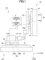
- Figure 1 is a diagram illustrating a machine tool 100 having a control apparatus C that is a first embodiment of the present invention.
- the machine tool 100 includes a spindle 110 and a cutting tool rest 130A.
- the spindle 110 has a chuck 120 provided at a tip thereof.
- a workpiece W is held by the spindle 110 via the chuck 120, and the spindle 110 is configured as workpiece holding means to hold a workpiece.
- the spindle 110 is supported by a spindle stock 110A so as to be rotatably driven by a spindle motor that is not shown.
- spindle motor a conventional built-in motor or the like formed between the spindle stock 110A and the spindle 110 may be used in the spindle stock 110A.
- the spindle stock 110A is mounted on a bed side of the machine tool 100 so as to be movable in a Z-axis direction, which is an axis direction of the spindle 110, by a Z-axis direction feeding mechanism 160.
- the spindle 110 moves in the Z-axis direction by the Z-axis direction feeding mechanism 160 via the spindle stock 110A.
- the Z-axis direction feeding mechanism 160 constitutes a spindle moving mechanism for moving the spindle 110 in the X-axis direction.
- the Z-axis direction feeding mechanism 160 includes a base 161, which is integral with a side on which the Z-axis direction feeding mechanism 160 is fixed, such as the bed side, and a Z-axis direction guide rail 162 provided on the base 161 so as to extend in the Z-axis direction.
- a Z-axis direction feeding table 163 is slidably supported on the Z-axis direction guide rail 162 via a Z-axis direction guide 164.
- a mover 165a of a linear servo motor 165 is provided on the side of the Z-axis direction feeding table 163, and a stator 165b of the linear servo motor 165 is provided on the side of the base 161.
- the spindle stock 110A is mounted on the Z-axis direction feeding table 163, and the Z-axis direction feeding table 163 is driven by the linear servo motor 165 to move in the Z-axis direction.
- the spindle stock 110A moves in the Z-axis direction, making the spindle 110 move in the X-axis direction.
- a cutting tool 130 such as a bite, for cutting the workpiece W is attached to the cutting tool rest 130A.
- the cutting tool rest 130A constitutes a tool rest that holds the cutting tool 130.
- the cutting tool rest 130A is provided on a bed side of the machine tool 100 so as to be movable in an X-axis direction, which is perpendicular to the Z-axis direction, and in a Y-axis direction, which is perpendicular to both the Z-axis direction and the X-axis direction, by an X-axis direction feeding mechanism 150 and a Y-axis direction feeding mechanism that is not illustrated.
- the X-axis direction feeding mechanism 150 and the Y-axis direction feeding mechanism constitute a tool rest moving mechanism for moving the cutting tool rest 130A in the X-axis direction and the Y-axis direction with respect to the spindle 110.
- the X-axis direction feeding mechanism 150 includes a base 151, which is integral with a side on which the X-axis direction feeding mechanism 150 is fixed, and an X-axis direction guide rail 152 provided on the base 151 so as to extend in the X-axis direction.
- An X-axis direction feeding table 153 is slidably supported on the X-axis direction guide rail 152 via an X-axis direction guide 154.
- a mover 155a of a linear servo motor 155 is provided on the side of the X-axis direction feeding table 153, and a stator 155b of the linear servo motor 155 is provided on the side of the base 151.
- the X-axis direction feeding table 153 is driven by the linear servo motor 155 to move in the X-axis direction.
- the Y-axis direction feeding mechanism is structurally similar to the X-axis direction feeding mechanism 150, except being arranged in the Y-axis direction. Thus, the detailed description and illustration of the Y-axis direction feeding mechanism are omitted.
- the X-axis direction feeding mechanism 150 is mounted on the bed side via the Y-axis direction feeding mechanism that is not shown, and the cutting tool rest 130A is mounted on the X-axis direction feeding table 153.
- the cutting tool rest 130A moves in the X-axis direction by being driven by the X-axis direction feeding table 153, and also moves in the Y-axis direction by being driven by the Y-axis direction feeding mechanism, which operates similarly to the X-axis direction feeding mechanism 150.
- the Y-axis direction feeding mechanism that is not shown may be mounted on the bed side via the X-axis direction feeding mechanism 150, and the cutting tool rest 130A may be mounted on the side of the Y-axis direction feeding mechanism.
- the structure for moving the cutting tool rest 130A in the X-axis direction and the Y-axis direction by the X-axis direction feeding mechanism and the Y-axis direction feeding mechanism 150 is conventionally known and thus the detailed description and illustration of the structure are omitted.
- the tool rest moving mechanism (the X-axis direction feeding mechanism 150 and the Y-axis direction feeding mechanism) and the spindle moving mechanism (the Z-axis direction feeding mechanism 160) operate cooperatively, and the cutting tool 130 attached to the cutting tool rest 130A is fed in any feeding direction with respect to the workpiece W via the movement of the cutting tool rest 130A in the X-axis direction and the Y-axis direction by the X-axis direction feeding mechanism 150 and the Y-axis direction feeding mechanism as well as via the movement of the spindle stock 110A (the spindle 110) in the Z-axis direction by the Z-axis direction feeding mechanism 160.
- the workpiece W is cut with the cutting tool 130 into any shape by feeding the cutting tool 130 in any feeding direction with respect to the workpiece W by feeding means consisting of the spindle moving mechanism (the Z-axis direction feeding mechanism 160) and the tool rest moving mechanism (the X-axis direction feeding mechanism 150 and the Y-axis direction feeding mechanism).
- the spindle moving mechanism the Z-axis direction feeding mechanism 160
- the tool rest moving mechanism the X-axis direction feeding mechanism 150 and the Y-axis direction feeding mechanism
- both the spindle stock 11 0A and the cutting tool rest 130A are movable.
- the spindle stock 110A may be fixed on the bed side of the machine tool 100 and the tool rest moving mechanism may be configured to move the cutting tool rest 130A in the X-axis direction, the Y-axis direction, and the Z-axis direction.
- the feeding means may be consist of the tool rest moving mechanism that moves the cutting tool rest 130A in the X-axis direction, the Y-axis direction, and the Z-axis direction, and the cutting tool 130 may be fed toward the workpiece W by moving the cutting tool rest 130A with respect to the spindle 110 that is fixedly positioned and rotatably driven.
- the cutting tool rest 130A may be fixed on the bed side of the machine tool 100 so as to be not movable and the spindle moving mechanism may be configured to move the spindle stock 110A in the X-axis direction, the Y-axis direction, and the Z-axis direction.
- the feeding means may be consist of the spindle moving mechanism that moves the spindle stock 110A in the X-axis direction, the Y-axis direction, and the Z-axis direction, and the cutting tool 130 may be fed toward the workpiece W by moving the spindle stock 110A with respect to the cutting tool rest 130A that is fixedly positioned.
- the X-axis direction feeding mechanism 150, the Y-axis direction feeding mechanism, and the Z-axis direction feeding mechanism 160 are configured to be driven by a linear servo motor in this embodiment, they may be driven by a conventional mechanism consisting of a ball screw and a servo motor, for example.
- rotating means to relatively rotate the workpiece W and the cutting tool 130 consists of the spindle motor such as the built-in motor, and the relative rotation between the workpiece W and the cutting tool 130 is achieved by rotatably driving the spindle 110.
- the cutting tool 130 may be rotated with respect to the workpiece W.
- a rotating tool such as a drill may be used as the cutting tool 130.
- the rotation of the spindle 110, the Z-axis direction feeding mechanism 160, the X-axis direction feeding mechanism 150, and the Y-axis direction feeding mechanism are driven and controlled by a control part C1 of the control apparatus C.
- the control part C1 is preconfigured to control so that the spindle stock 110A or the cutting tool rest 130A moves in any one of the X-axis direction, the Y-axis direction, and the Z-axis direction while the spindle 110 or the cutting tool 130 reciprocally vibrates in the any one of the X-axis direction, the Y-axis direction, and the Z-axis direction by utilizing one of the feeding mechanisms as vibration means .
- each of the feeding mechanisms forwardly moves the spindle 110 or the cutting tool rest 130A (forward movement) for a predetermined forward movement amount and then backwardly moves the spindle 110 or the cutting tool rest 130A (backward movement) for a predetermined backward movement amount in each reciprocal vibration, so that the spindle 110 or the cutting tool rest 130A moves in a respective direction for an advancing amount that is equal to the difference between the forward movement amount and the backward movement amount.
- the feeding mechanisms cooperatively feed the cutting tool 130 toward the workpiece W in any feeding direction.
- the machine tool 100 machines the workpiece W by feeding the cutting tool 130 in a feeding direction while reciprocally vibrating the cutting tool 130 in the feeding direction.
- spindle stock 110A spindle 110
- the cutting tool rest 130A cutting tool 130
- phase of the shape of the circumferential surface of the workpiece W cut with the cutting tool 130 during the n+1th rotation of the workpiece W (n is an integer equal to or larger than one) is opposite to the phase of the shape of the circumferential surface of the workpiece W cut with the cutting tool 130 during the nth rotation of the workpiece W.
- a cutting work position of the forward movement of the cutting tool 130 during the nth rotation of the workpiece W partially overlaps with a cutting work position of the backward movement of the cutting tool 130 during the n+1th rotation of the workpiece W.
- a portion of the circumferential surface of the workpiece W that is cut during the n+1th rotation includes a portion that has already been cut during the nth rotation.
- the cutting tool 130 performs an air cut, in which the cutting tool 130 does not cut the workpiece W at all.
- the machine tool 100 can smoothly machine an outer surface of the workpiece W, for example, while separating a chip via the reciprocal vibration of the cutting tool 130 in a feeding direction.
- a portion of the circumferential surface of the workpiece W that is cut during the n+1th rotation simply needs to include a portion that has already been cut during the nth rotation.
- a path traced by the cutting tool 130 on the circumferential surface of the workpiece W in the backward movement during the n+1th rotation of the workpiece W simply needs to reach a path traced by the cutting tool 130 on the circumferential surface of the workpiece W during the nth rotation of the workpiece W.
- the phase of the shape of the circumferential surface of the workpiece W cut with the cutting tool 130 during the n+1th rotation of the workpiece W simply needs to be not coincident with (not the same as) the phase of the shape of the circumferential surface of the workpiece cut with the cutting tool 130 during the nth rotation of the workpiece W, and do not need to be a 180 degrees inversion of the phase of the shape of the circumferential surface of the workpiece cut with the cutting tool 130 during the nth rotation of the workpiece W.
- Machining with the cutting tool 130 is performed via a move instruction to move the cutting tool 130 to a particular coordinate position. Due to this move instruction, the cutting tool 130 moves to and stops at a coordinate position (cutting tool work stopping position) specified in the move instruction.
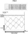
- the cutting tool 130 machines the workpiece W by being fed toward the workpiece W in a feeding direction while reciprocally vibrating in the feeding direction as the workpiece W rotates, and that the cutting tool 130 reaches the cutting tool work stopping position in the forward movement thereof during the fifth rotation of the workpiece W.
- control part C1 functions as amplitude control means. Due to the control performed by the control part C1, the reciprocal vibration is performed while a predetermined amplitude is maintained during the first to fourth rotations of the workpiece W. During the fifth rotation of the workpiece W, the amplitude of the reciprocal vibration by the vibration means starts reducing while the position of the cutting tool 130 as the forward movement switches to the backward movement is maintained on the cutting tool work stopping position. During the sixth and seventh rotations of the workpiece W, the cutting work is performed as the position of the cutting tool 130 as the backward movement switches to the forward movement is gradually changed.
- the amplitude of the reciprocal vibration by the vibration means while the cutting tool 130 is fed in a feeding direction is reduced while the path traced by the cutting tool 130 in the backward movement during the n+1th rotation of the workpiece W reaches the path traced by the cutting tool 130 during the nth rotation of the workpiece W.
- the vibration means vibrates the cutting tool 130 so that the cutting work position of the forward movement of the reciprocal vibration overlaps with the cutting work position of the backward movement of the reciprocal vibration to cut the workpiece W while the control part C1 as the amplitude control means reduces the amplitude of the reciprocal vibration as the cutting tool 130 is fed in the feeding direction.
- the amplitude becomes smaller while a chip is sequentially separated.
- the reciprocal vibration by the vibration means stops so that the cutting tool 130 cuts the workpiece W while being maintained at the cutting tool work stopping position.
- the vibration frequency of the reciprocal vibration during the first to seventh rotations of the workpiece W is kept constant.
- the vibration frequency may not be constant as long as the path traced by the cutting tool 130 on the circumferential surface of the workpiece in the backward movement during the n+1th rotation of the workpiece W reaches the path traced by the cutting tool 130 on the circumferential surface of the workpiece during the nth rotation of the workpiece W.
- the machine tool 100 and the control apparatus C of the machine tool 100 as the first embodiment of the present invention obtained as described above includes the control part C1, which is also the amplitude control means, to control the amplitude of the reciprocal vibration by the vibration means, and the control part C1 as the amplitude control means is configured to reduce the amplitude of the reciprocal vibration by the vibration means while the cutting tool 130 is fed in the feeding direction when the cutting tool 130 reaches the cutting tool work stopping position on the workpiece W.
- the control part C1 as the amplitude control means is configured to reduce the amplitude of the reciprocal vibration by the vibration means while the cutting tool 130 is fed in the feeding direction when the cutting tool 130 reaches the cutting tool work stopping position on the workpiece W.
- control part C1 as the amplitude control means can be configured to start reducing the amplitude when the cutting tool 130 in the forward movement reaches the cutting tool work stopping position and to reduce the amplitude by gradually changing the position of the cutting tool 130 as the backward movement switches to the forward movement while maintaining the position of the cutting tool 130 as the forward movement switches to the backward movement on the cutting tool work stopping position.
- control part C1 as the amplitude control means can stop the reciprocal vibration by the vibration means so that, after the cutting tool 130 reaches the cutting tool work stopping position and the reciprocal vibration is performed for a predetermined number of times while the amplitude is reduced, the cutting tool 130 cuts the workpiece W while being maintained at the cutting tool work stopping position.
- the surface of the workpiece W at the cutting tool work stopping position which is in a wavy shape due to the reciprocal vibration, can be finished flat.
- control part C1 as the amplitude control means is configured to start reducing the amplitude when the cutting tool 130 reaches any predetermined position located in front of the cutting tool work stopping position for performing the cutting work during the fifth to seventh rotations of the workpiece W while the amplitude is reduced, and to reduce the amplitude so that the position of the cutting tool 130 as the forward movement switches to the backward movement at the end of the seventh rotation reaches the cutting tool work stopping position to end the reciprocal vibration.
- the cutting tool 130 cuts the workpiece W while being located at the cutting tool work stopping position without the reciprocal vibration.
- the machine tool 100 and the control apparatus C of the machine tool 100 as the second embodiment of the present invention obtained as described above includes the control part C1 as the amplitude control means that is configured to start reducing the amplitude when the cutting tool 130 reaches any predetermined position located in front of the cutting tool work stopping position on the workpiece W and to reduce the amplitude so that the position of the cutting tool 130 as the forward movement switches to the backward movement reaches the cutting tool work stopping position to end the reciprocal vibration.
- the same effects as the first embodiment can be achieved.
- the reciprocal vibration is performed by the vibration means such that the forward movement is performed for a predetermined forward movement amount and then the backward movement is performed for a predetermined backward movement amount.
- the reciprocal vibration may be performed by repeating relative movement at a first speed as the forward movement and relative movement at a second speed as the backward movement, wherein the second speed is set to zero to stop the reciprocal vibration.
- the relative movement at the second speed may be performed in the same direction as the relative movement at a speed slower than the first speed.
- a chip generated from the workpiece W can be easily folded and separated into chip powder at a portion of the chip where the width of the chip become narrower.
Claims (4)
- Werkzeugmaschine (100), umfassend:Werkstückhaltemittel zum Halten eines Werkstücks (W),einen Werkzeughalter (130A) zum Halten eines Schneidwerkzeugs (130) zum Schneiden des Werkstücks (W),Vorschubmittel (150, 160) zum Vorschieben des Schneidwerkzeugs (130) in Richtung auf das Werkstück (W) in einer vorbestimmten Vorschubrichtung über eine Relativbewegung zwischen dem Werkstückhaltemittel und dem Werkzeughalter (130A);ein Vibrationsmittel zum relativen Vibrieren des Werkstückhaltemittels und des Werkzeughalters (130A), so dass das Schneidwerkzeug (130) in der Vorschubrichtung vorgeschoben wird, während es in der Vorschubrichtung hin und her vibriert, undDrehmittel zum relativen Drehen des Werkstücks (W) und des Schneidwerkzeugs (130),wobei die Werkzeugmaschine (100) in der Lage ist, das Werkstück (W) über die Relativdrehung zwischen dem Werkstück (W) und dem Schneidwerkzeug (130) und über den Vorschub des Schneidwerkzeugs (130) in Richtung des Werkstücks (W) mit der reziproken Vibration (N) in der Vorschubrichtung zu schneiden,wobei die Werkzeugmaschine (100) ein Amplitudensteuermittel aufweist, um eine Amplitude der reziproken Vibration (N) durch die Vibrationsmittel zu steuern, wobei die Werkzeugmaschine dadurch gekennzeichnet ist, dassdas Amplitudensteuermittel konfiguriert ist, um die Amplitude der reziproken Vibration (N) durch das Vibrationsmittel zu reduzieren, während das Schneidwerkzeug (130) in der Vorschubrichtung vorgeschoben wird, wenn das Schneidwerkzeug (130) eine vorbestimmte Koordinatenposition auf dem Werkstück (W) erreicht, die in einer bestimmten Bewegungsinstruktion spezifiziert ist, um das Schneidwerkzeug (130) in der Vorschubrichtung zu bewegen.
- Werkzeugmaschine (100) nach Anspruch 1, wobei das Vibrationsmittel konfiguriert ist, das Werkstückhaltemittel und den Werkzeughalter (130A) relativ zueinander zu vibrieren, so dass eine Schneidarbeitsposition der Vorwärtsbewegung der reziproken Vibration (N) des Schneidwerkzeugs (130) während einer n-ten Drehung des Werkstücks (W) mit einer Schneidarbeitsposition der Rückwärtsbewegung der reziproken Vibration (N) des Schneidwerkzeugs (130) während einer n+1-ten Drehung des Werkstücks (W) überlappt, was bedeutet, dass ein Abschnitt einer Umfangsfläche des Werkstücks (W), der während der n+1-ten Drehung geschnitten wird, einen Abschnitt umfasst, der bereits während der n-ten Drehung geschnitten worden ist, wobei in diesem Abschnitt das Schneidwerkzeug (130) einen Luftschnitt durchführt, bei dem das Schneidwerkzeug (130) das Werkstück (W) überhaupt nicht schneidet, und
das Vibrationsmittel und das Amplitudensteuermittel konfiguriert sind, um so zusammenzuwirken, dass die Amplitude der reziproken Vibration (N) reduziert wird, während die Überlappung der Schneidarbeitsposition der Vorwärtsbewegung der reziproken Vibration (N) des Schneidwerkzeugs (130) während einer n-ten Drehung des Werkstücks (W) mit der Schneidarbeitsposition der Rückwärtsbewegung der reziproken Vibration (N) des Schneidwerkzeugs (130) während einer n+1-ten Drehung des Werkstücks (W) beibehalten wird. - Werkzeugmaschine (100) nach Anspruch 1 oder 2, wobei das Amplitudensteuermittel so konfiguriert ist, dass es mit der Verringerung der Amplitude beginnt, wenn das Schneidwerkzeug (130) bei der Vorwärtsbewegung die Koordinatenposition erreicht, und dass es die Amplitude verringert, indem es die Position des Schneidwerkzeugs (130) allmählich ändert, wenn die Rückwärtsbewegung auf die Vorwärtsbewegung umschaltet, während es die Position des Schneidwerkzeugs (130) beibehält, wenn die Vorwärtsbewegung auf die Rückwärtsbewegung an der Koordinatenposition umschaltet.
- Werkzeugmaschine (100) nach einem der Ansprüche 1 bis 3, wobei das Amplitudensteuermittel so konfiguriert ist, dass es die reziproke Vibration (N) durch das Vibrationsmittel stoppt, so dass, nachdem das Schneidwerkzeug (130) die Koordinatenposition erreicht hat und die reziproke Vibration (N) für eine vorbestimmte Anzahl von Malen ausgeführt worden ist, während die Amplitude reduziert wird, das Schneidwerkzeug (130) das Werkstück (W) schneidet, während es in der Koordinatenposition gehalten wird.
Applications Claiming Priority (2)
| Application Number | Priority Date | Filing Date | Title |
|---|---|---|---|
| JP2014192950 | 2014-09-22 | ||
| PCT/JP2015/076008 WO2016047485A1 (ja) | 2014-09-22 | 2015-09-14 | 工作機械及びこの工作機械の制御装置 |
Publications (3)
| Publication Number | Publication Date |
|---|---|
| EP3199271A1 EP3199271A1 (de) | 2017-08-02 |
| EP3199271A4 EP3199271A4 (de) | 2018-06-06 |
| EP3199271B1 true EP3199271B1 (de) | 2020-08-12 |
Family
ID=55581012
Family Applications (1)
| Application Number | Title | Priority Date | Filing Date |
|---|---|---|---|
| EP15843568.5A Active EP3199271B1 (de) | 2014-09-22 | 2015-09-14 | Werkzeugmaschine und steuerungsvorrichtung für werkzeugmaschine |
Country Status (8)
| Country | Link |
|---|---|
| US (1) | US11338404B2 (de) |
| EP (1) | EP3199271B1 (de) |
| JP (1) | JP6297711B2 (de) |
| KR (1) | KR102183278B1 (de) |
| CN (1) | CN106687237B (de) |
| ES (1) | ES2813968T3 (de) |
| TW (1) | TWI657889B (de) |
| WO (1) | WO2016047485A1 (de) |
Families Citing this family (16)
| Publication number | Priority date | Publication date | Assignee | Title |
|---|---|---|---|---|
| CN108025412B (zh) * | 2015-09-24 | 2020-03-06 | 西铁城时计株式会社 | 机床的控制装置以及具备该控制装置的机床 |
| JP6412197B1 (ja) | 2017-04-04 | 2018-10-24 | ファナック株式会社 | 揺動切削を行う工作機械の制御装置 |
| JP6499709B2 (ja) | 2017-04-14 | 2019-04-10 | ファナック株式会社 | 揺動切削を行う工作機械の制御装置 |
| JP6503001B2 (ja) * | 2017-04-18 | 2019-04-17 | ファナック株式会社 | 揺動切削を行う工作機械の制御装置 |
| JP6503000B2 (ja) * | 2017-04-18 | 2019-04-17 | ファナック株式会社 | 揺動切削を行う工作機械の制御装置 |
| JP6503002B2 (ja) | 2017-04-20 | 2019-04-17 | ファナック株式会社 | 揺動切削を行う工作機械の制御装置 |
| JP6530780B2 (ja) | 2017-05-16 | 2019-06-12 | ファナック株式会社 | 揺動切削のための表示装置および加工システム |
| JP6595537B2 (ja) * | 2017-07-27 | 2019-10-23 | ファナック株式会社 | 揺動切削を行う工作機械の制御装置 |
| JP6991774B2 (ja) * | 2017-08-01 | 2022-01-13 | シチズン時計株式会社 | 工作機械の制御装置および工作機械 |
| KR102613333B1 (ko) * | 2017-09-12 | 2023-12-14 | 시티즌 도케이 가부시키가이샤 | 공작기계 |
| WO2019073907A1 (ja) | 2017-10-13 | 2019-04-18 | シチズン時計株式会社 | 工作機械 |
| US11491672B2 (en) * | 2018-09-21 | 2022-11-08 | Dexerials Corporation | Microfabrication device, microfabrication method, transfer mold, and transfer object |
| JP7264643B2 (ja) * | 2019-01-10 | 2023-04-25 | シチズン時計株式会社 | 工作機械の制御装置および工作機械 |
| JP6912506B2 (ja) * | 2019-03-06 | 2021-08-04 | ファナック株式会社 | 工作機械の制御装置 |
| US11148208B2 (en) * | 2020-02-03 | 2021-10-19 | The Boeing Company | Vibration assisted drilling system and method of use |
| JP7464721B2 (ja) | 2020-07-29 | 2024-04-09 | ファナック株式会社 | 工作機械の制御装置 |
Family Cites Families (29)
| Publication number | Priority date | Publication date | Assignee | Title |
|---|---|---|---|---|
| US3174404A (en) * | 1959-06-15 | 1965-03-23 | Textron Inc | Method and apparatus for cutting material |
| US3699719A (en) * | 1971-01-25 | 1972-10-24 | Nicholas Rozdilsky | Ultrasonic machining |
| JPS5033929B2 (de) | 1973-10-19 | 1975-11-05 | ||
| JPS5715626A (en) * | 1980-06-24 | 1982-01-27 | Pilot Pen Co Ltd:The | Accurate thread vibration cutting lathe |
| GB2170135B (en) * | 1985-01-28 | 1988-09-01 | Bergsmann App Ludwig | Method of and apparatus for chip-cutting of workpieces |
| DE3563922D1 (en) * | 1985-04-09 | 1988-09-01 | Hegenscheidt Gmbh Wilhelm | Method to obtain broken chips during the machining of work pieces, and device therefor |
| JPS61252056A (ja) * | 1985-04-30 | 1986-11-10 | Canon Inc | 振動研摩加工法 |
| JPH0463668A (ja) * | 1990-07-03 | 1992-02-28 | Brother Ind Ltd | 超音波加工機の振幅制御装置 |
| JP3088537B2 (ja) * | 1991-12-11 | 2000-09-18 | 株式会社不二越 | 高硬度材の孔の仕上げ加工方法及び加工装置 |
| US5582085A (en) * | 1994-11-09 | 1996-12-10 | Coburn Optical Industries, Inc. | Dynamic infeed control with workpiece oscillation for segmenting swarf in a lathe application |
| JPH1015701A (ja) * | 1996-07-04 | 1998-01-20 | Mitsubishi Materials Corp | 振動バイトによる切削方法 |
| JP2001150201A (ja) * | 1999-11-22 | 2001-06-05 | Mitsubishi Materials Corp | 振動工具による切削方法及び切削装置 |
| JP2002103101A (ja) * | 2000-09-22 | 2002-04-09 | Matsushita Electric Ind Co Ltd | 切屑分断化旋削方法及びその装置 |
| JP4539499B2 (ja) * | 2004-11-09 | 2010-09-08 | 株式会社デンソー | 振動加工装置及び振動加工方法 |
| JP2006312223A (ja) * | 2005-05-09 | 2006-11-16 | Toyota Motor Corp | 切削加工装置、及び方法 |
| US7234379B2 (en) * | 2005-06-28 | 2007-06-26 | Ingvar Claesson | Device and a method for preventing or reducing vibrations in a cutting tool |
| US7508116B2 (en) * | 2005-09-07 | 2009-03-24 | Panasonic Corporation | Method and apparatus for vibration machining with two independent axes |
| US8240234B2 (en) * | 2007-10-16 | 2012-08-14 | University Of North Carolina At Charlotte | Methods and systems for chip breaking in turning applications using CNC toolpaths |
| JP4942839B2 (ja) * | 2010-09-10 | 2012-05-30 | 株式会社牧野フライス製作所 | びびり振動検出方法及びびびり振動回避方法、並びに工作機械 |
| DE102011077568B4 (de) * | 2011-06-15 | 2023-12-07 | Dmg Mori Ultrasonic Lasertec Gmbh | Werkzeugmaschine, Werkstückbearbeitungsverfahren |
| JP5033929B1 (ja) * | 2011-11-10 | 2012-09-26 | ハリキ精工株式会社 | 工作機械 |
| JP5908342B2 (ja) * | 2012-05-17 | 2016-04-26 | オークマ株式会社 | 工作機械の加工振動抑制方法及び加工振動抑制装置 |
| CN202639335U (zh) * | 2012-07-02 | 2013-01-02 | 赵显华 | 超声波振动车削装置 |
| WO2014125569A1 (ja) * | 2013-02-12 | 2014-08-21 | 三菱電機株式会社 | 数値制御装置 |
| EP4245443A1 (de) * | 2014-08-29 | 2023-09-20 | Citizen Watch Co., Ltd. | Werkzeugmaschine und steuerungsvorrichtung für werkzeugmaschine |
| JP6470085B2 (ja) * | 2015-03-26 | 2019-02-13 | シチズン時計株式会社 | 工作機械及びこの工作機械の制御装置 |
| TWI693120B (zh) * | 2015-09-10 | 2020-05-11 | 日商西鐵城時計股份有限公司 | 工具機的控制裝置以及工具機 |
| CN108025412B (zh) * | 2015-09-24 | 2020-03-06 | 西铁城时计株式会社 | 机床的控制装置以及具备该控制装置的机床 |
| US10744611B2 (en) * | 2015-09-24 | 2020-08-18 | Citizen Watch Co., Ltd. | Machine tool control device and machine tool equipped with said control device |
-
2015
- 2015-09-14 WO PCT/JP2015/076008 patent/WO2016047485A1/ja active Application Filing
- 2015-09-14 ES ES15843568T patent/ES2813968T3/es active Active
- 2015-09-14 TW TW104130290A patent/TWI657889B/zh active
- 2015-09-14 KR KR1020177010761A patent/KR102183278B1/ko active IP Right Grant
- 2015-09-14 US US15/512,989 patent/US11338404B2/en active Active
- 2015-09-14 CN CN201580051234.1A patent/CN106687237B/zh active Active
- 2015-09-14 JP JP2016550111A patent/JP6297711B2/ja active Active
- 2015-09-14 EP EP15843568.5A patent/EP3199271B1/de active Active
Non-Patent Citations (1)
| Title |
|---|
| None * |
Also Published As
| Publication number | Publication date |
|---|---|
| CN106687237B (zh) | 2018-11-09 |
| KR102183278B1 (ko) | 2020-11-26 |
| US11338404B2 (en) | 2022-05-24 |
| EP3199271A4 (de) | 2018-06-06 |
| KR20170058421A (ko) | 2017-05-26 |
| JP6297711B2 (ja) | 2018-03-20 |
| US20170297159A1 (en) | 2017-10-19 |
| ES2813968T3 (es) | 2021-03-25 |
| TWI657889B (zh) | 2019-05-01 |
| EP3199271A1 (de) | 2017-08-02 |
| JPWO2016047485A1 (ja) | 2017-07-06 |
| CN106687237A (zh) | 2017-05-17 |
| WO2016047485A1 (ja) | 2016-03-31 |
| TW201611941A (en) | 2016-04-01 |
Similar Documents
| Publication | Publication Date | Title |
|---|---|---|
| EP3199271B1 (de) | Werkzeugmaschine und steuerungsvorrichtung für werkzeugmaschine | |
| EP3205430B1 (de) | Verfahren zur erzeugung einer gewinde | |
| US10414010B2 (en) | Machine tool and control apparatus of the machine tool | |
| EP3275591B1 (de) | Werkzeugmaschine und steuerungsvorrichtung für diese werkzeugmaschine | |
| CN110475637B (zh) | 机床的控制装置以及机床 | |
| JP6727190B2 (ja) | 工作機械及びこの工作機械の制御装置 | |
| TWI765105B (zh) | 工作機械 | |
| JP2016182652A (ja) | 工作機械及びこの工作機械の制御装置 | |
| JP2020013355A (ja) | 工作機械の制御装置および工作機械 | |
| EP3696634B1 (de) | Werkzeugmaschine | |
| CN111133393B (zh) | 机床 |
Legal Events
| Date | Code | Title | Description |
|---|---|---|---|
| STAA | Information on the status of an ep patent application or granted ep patent |
Free format text: STATUS: THE INTERNATIONAL PUBLICATION HAS BEEN MADE |
|
| PUAI | Public reference made under article 153(3) epc to a published international application that has entered the european phase |
Free format text: ORIGINAL CODE: 0009012 |
|
| STAA | Information on the status of an ep patent application or granted ep patent |
Free format text: STATUS: REQUEST FOR EXAMINATION WAS MADE |
|
| 17P | Request for examination filed |
Effective date: 20170227 |
|
| AK | Designated contracting states |
Kind code of ref document: A1 Designated state(s): AL AT BE BG CH CY CZ DE DK EE ES FI FR GB GR HR HU IE IS IT LI LT LU LV MC MK MT NL NO PL PT RO RS SE SI SK SM TR |
|
| AX | Request for extension of the european patent |
Extension state: BA ME |
|
| DAV | Request for validation of the european patent (deleted) | ||
| DAX | Request for extension of the european patent (deleted) | ||
| A4 | Supplementary search report drawn up and despatched |
Effective date: 20180508 |
|
| RIC1 | Information provided on ipc code assigned before grant |
Ipc: B23Q 15/013 20060101ALI20180502BHEP Ipc: B23Q 15/12 20060101ALI20180502BHEP Ipc: B23Q 15/007 20060101ALI20180502BHEP Ipc: B23B 29/12 20060101ALI20180502BHEP Ipc: B23B 25/02 20060101ALI20180502BHEP Ipc: B23B 1/00 20060101AFI20180502BHEP |
|
| GRAP | Despatch of communication of intention to grant a patent |
Free format text: ORIGINAL CODE: EPIDOSNIGR1 |
|
| STAA | Information on the status of an ep patent application or granted ep patent |
Free format text: STATUS: GRANT OF PATENT IS INTENDED |
|
| INTG | Intention to grant announced |
Effective date: 20200515 |
|
| GRAS | Grant fee paid |
Free format text: ORIGINAL CODE: EPIDOSNIGR3 |
|
| GRAA | (expected) grant |
Free format text: ORIGINAL CODE: 0009210 |
|
| STAA | Information on the status of an ep patent application or granted ep patent |
Free format text: STATUS: THE PATENT HAS BEEN GRANTED |
|
| AK | Designated contracting states |
Kind code of ref document: B1 Designated state(s): AL AT BE BG CH CY CZ DE DK EE ES FI FR GB GR HR HU IE IS IT LI LT LU LV MC MK MT NL NO PL PT RO RS SE SI SK SM TR |
|
| REG | Reference to a national code |
Ref country code: CH Ref legal event code: EP |
|
| REG | Reference to a national code |
Ref country code: IE Ref legal event code: FG4D |
|
| REG | Reference to a national code |
Ref country code: DE Ref legal event code: R096 Ref document number: 602015057485 Country of ref document: DE |
|
| REG | Reference to a national code |
Ref country code: AT Ref legal event code: REF Ref document number: 1301060 Country of ref document: AT Kind code of ref document: T Effective date: 20200915 Ref country code: CH Ref legal event code: NV Representative=s name: SCHMAUDER AND PARTNER AG PATENT- UND MARKENANW, CH |
|
| REG | Reference to a national code |
Ref country code: LT Ref legal event code: MG4D |
|
| REG | Reference to a national code |
Ref country code: NL Ref legal event code: MP Effective date: 20200812 |
|
| PG25 | Lapsed in a contracting state [announced via postgrant information from national office to epo] |
Ref country code: NO Free format text: LAPSE BECAUSE OF FAILURE TO SUBMIT A TRANSLATION OF THE DESCRIPTION OR TO PAY THE FEE WITHIN THE PRESCRIBED TIME-LIMIT Effective date: 20201112 Ref country code: GR Free format text: LAPSE BECAUSE OF FAILURE TO SUBMIT A TRANSLATION OF THE DESCRIPTION OR TO PAY THE FEE WITHIN THE PRESCRIBED TIME-LIMIT Effective date: 20201113 Ref country code: SE Free format text: LAPSE BECAUSE OF FAILURE TO SUBMIT A TRANSLATION OF THE DESCRIPTION OR TO PAY THE FEE WITHIN THE PRESCRIBED TIME-LIMIT Effective date: 20200812 Ref country code: BG Free format text: LAPSE BECAUSE OF FAILURE TO SUBMIT A TRANSLATION OF THE DESCRIPTION OR TO PAY THE FEE WITHIN THE PRESCRIBED TIME-LIMIT Effective date: 20201112 Ref country code: LT Free format text: LAPSE BECAUSE OF FAILURE TO SUBMIT A TRANSLATION OF THE DESCRIPTION OR TO PAY THE FEE WITHIN THE PRESCRIBED TIME-LIMIT Effective date: 20200812 Ref country code: FI Free format text: LAPSE BECAUSE OF FAILURE TO SUBMIT A TRANSLATION OF THE DESCRIPTION OR TO PAY THE FEE WITHIN THE PRESCRIBED TIME-LIMIT Effective date: 20200812 Ref country code: HR Free format text: LAPSE BECAUSE OF FAILURE TO SUBMIT A TRANSLATION OF THE DESCRIPTION OR TO PAY THE FEE WITHIN THE PRESCRIBED TIME-LIMIT Effective date: 20200812 |
|
| REG | Reference to a national code |
Ref country code: AT Ref legal event code: MK05 Ref document number: 1301060 Country of ref document: AT Kind code of ref document: T Effective date: 20200812 |
|
| PG25 | Lapsed in a contracting state [announced via postgrant information from national office to epo] |
Ref country code: RS Free format text: LAPSE BECAUSE OF FAILURE TO SUBMIT A TRANSLATION OF THE DESCRIPTION OR TO PAY THE FEE WITHIN THE PRESCRIBED TIME-LIMIT Effective date: 20200812 Ref country code: LV Free format text: LAPSE BECAUSE OF FAILURE TO SUBMIT A TRANSLATION OF THE DESCRIPTION OR TO PAY THE FEE WITHIN THE PRESCRIBED TIME-LIMIT Effective date: 20200812 Ref country code: PL Free format text: LAPSE BECAUSE OF FAILURE TO SUBMIT A TRANSLATION OF THE DESCRIPTION OR TO PAY THE FEE WITHIN THE PRESCRIBED TIME-LIMIT Effective date: 20200812 Ref country code: NL Free format text: LAPSE BECAUSE OF FAILURE TO SUBMIT A TRANSLATION OF THE DESCRIPTION OR TO PAY THE FEE WITHIN THE PRESCRIBED TIME-LIMIT Effective date: 20200812 Ref country code: IS Free format text: LAPSE BECAUSE OF FAILURE TO SUBMIT A TRANSLATION OF THE DESCRIPTION OR TO PAY THE FEE WITHIN THE PRESCRIBED TIME-LIMIT Effective date: 20201212 |
|
| REG | Reference to a national code |
Ref country code: ES Ref legal event code: FG2A Ref document number: 2813968 Country of ref document: ES Kind code of ref document: T3 Effective date: 20210325 |
|
| PG25 | Lapsed in a contracting state [announced via postgrant information from national office to epo] |
Ref country code: DK Free format text: LAPSE BECAUSE OF FAILURE TO SUBMIT A TRANSLATION OF THE DESCRIPTION OR TO PAY THE FEE WITHIN THE PRESCRIBED TIME-LIMIT Effective date: 20200812 Ref country code: CZ Free format text: LAPSE BECAUSE OF FAILURE TO SUBMIT A TRANSLATION OF THE DESCRIPTION OR TO PAY THE FEE WITHIN THE PRESCRIBED TIME-LIMIT Effective date: 20200812 Ref country code: EE Free format text: LAPSE BECAUSE OF FAILURE TO SUBMIT A TRANSLATION OF THE DESCRIPTION OR TO PAY THE FEE WITHIN THE PRESCRIBED TIME-LIMIT Effective date: 20200812 Ref country code: SM Free format text: LAPSE BECAUSE OF FAILURE TO SUBMIT A TRANSLATION OF THE DESCRIPTION OR TO PAY THE FEE WITHIN THE PRESCRIBED TIME-LIMIT Effective date: 20200812 Ref country code: RO Free format text: LAPSE BECAUSE OF FAILURE TO SUBMIT A TRANSLATION OF THE DESCRIPTION OR TO PAY THE FEE WITHIN THE PRESCRIBED TIME-LIMIT Effective date: 20200812 |
|
| REG | Reference to a national code |
Ref country code: DE Ref legal event code: R097 Ref document number: 602015057485 Country of ref document: DE |
|
| PG25 | Lapsed in a contracting state [announced via postgrant information from national office to epo] |
Ref country code: MC Free format text: LAPSE BECAUSE OF FAILURE TO SUBMIT A TRANSLATION OF THE DESCRIPTION OR TO PAY THE FEE WITHIN THE PRESCRIBED TIME-LIMIT Effective date: 20200812 Ref country code: AL Free format text: LAPSE BECAUSE OF FAILURE TO SUBMIT A TRANSLATION OF THE DESCRIPTION OR TO PAY THE FEE WITHIN THE PRESCRIBED TIME-LIMIT Effective date: 20200812 Ref country code: AT Free format text: LAPSE BECAUSE OF FAILURE TO SUBMIT A TRANSLATION OF THE DESCRIPTION OR TO PAY THE FEE WITHIN THE PRESCRIBED TIME-LIMIT Effective date: 20200812 |
|
| PLBE | No opposition filed within time limit |
Free format text: ORIGINAL CODE: 0009261 |
|
| REG | Reference to a national code |
Ref country code: BE Ref legal event code: MM Effective date: 20200930 |
|
| STAA | Information on the status of an ep patent application or granted ep patent |
Free format text: STATUS: NO OPPOSITION FILED WITHIN TIME LIMIT |
|
| PG25 | Lapsed in a contracting state [announced via postgrant information from national office to epo] |
Ref country code: LU Free format text: LAPSE BECAUSE OF NON-PAYMENT OF DUE FEES Effective date: 20200914 Ref country code: SK Free format text: LAPSE BECAUSE OF FAILURE TO SUBMIT A TRANSLATION OF THE DESCRIPTION OR TO PAY THE FEE WITHIN THE PRESCRIBED TIME-LIMIT Effective date: 20200812 |
|
| 26N | No opposition filed |
Effective date: 20210514 |
|
| GBPC | Gb: european patent ceased through non-payment of renewal fee |
Effective date: 20201112 |
|
| PG25 | Lapsed in a contracting state [announced via postgrant information from national office to epo] |
Ref country code: FR Free format text: LAPSE BECAUSE OF NON-PAYMENT OF DUE FEES Effective date: 20201012 |
|
| PG25 | Lapsed in a contracting state [announced via postgrant information from national office to epo] |
Ref country code: IE Free format text: LAPSE BECAUSE OF NON-PAYMENT OF DUE FEES Effective date: 20200914 Ref country code: SI Free format text: LAPSE BECAUSE OF FAILURE TO SUBMIT A TRANSLATION OF THE DESCRIPTION OR TO PAY THE FEE WITHIN THE PRESCRIBED TIME-LIMIT Effective date: 20200812 Ref country code: BE Free format text: LAPSE BECAUSE OF NON-PAYMENT OF DUE FEES Effective date: 20200930 |
|
| PG25 | Lapsed in a contracting state [announced via postgrant information from national office to epo] |
Ref country code: GB Free format text: LAPSE BECAUSE OF NON-PAYMENT OF DUE FEES Effective date: 20201112 |
|
| PG25 | Lapsed in a contracting state [announced via postgrant information from national office to epo] |
Ref country code: IS Free format text: LAPSE BECAUSE OF FAILURE TO SUBMIT A TRANSLATION OF THE DESCRIPTION OR TO PAY THE FEE WITHIN THE PRESCRIBED TIME-LIMIT Effective date: 20201212 Ref country code: TR Free format text: LAPSE BECAUSE OF FAILURE TO SUBMIT A TRANSLATION OF THE DESCRIPTION OR TO PAY THE FEE WITHIN THE PRESCRIBED TIME-LIMIT Effective date: 20200812 Ref country code: MT Free format text: LAPSE BECAUSE OF FAILURE TO SUBMIT A TRANSLATION OF THE DESCRIPTION OR TO PAY THE FEE WITHIN THE PRESCRIBED TIME-LIMIT Effective date: 20200812 Ref country code: CY Free format text: LAPSE BECAUSE OF FAILURE TO SUBMIT A TRANSLATION OF THE DESCRIPTION OR TO PAY THE FEE WITHIN THE PRESCRIBED TIME-LIMIT Effective date: 20200812 |
|
| PG25 | Lapsed in a contracting state [announced via postgrant information from national office to epo] |
Ref country code: MK Free format text: LAPSE BECAUSE OF FAILURE TO SUBMIT A TRANSLATION OF THE DESCRIPTION OR TO PAY THE FEE WITHIN THE PRESCRIBED TIME-LIMIT Effective date: 20200812 |
|
| PG25 | Lapsed in a contracting state [announced via postgrant information from national office to epo] |
Ref country code: PT Free format text: LAPSE BECAUSE OF FAILURE TO SUBMIT A TRANSLATION OF THE DESCRIPTION OR TO PAY THE FEE WITHIN THE PRESCRIBED TIME-LIMIT Effective date: 20200812 |
|
| PGFP | Annual fee paid to national office [announced via postgrant information from national office to epo] |
Ref country code: IT Payment date: 20230810 Year of fee payment: 9 |
|
| PGFP | Annual fee paid to national office [announced via postgrant information from national office to epo] |
Ref country code: DE Payment date: 20230802 Year of fee payment: 9 |
|
| PGFP | Annual fee paid to national office [announced via postgrant information from national office to epo] |
Ref country code: ES Payment date: 20231003 Year of fee payment: 9 |
|
| PGFP | Annual fee paid to national office [announced via postgrant information from national office to epo] |
Ref country code: CH Payment date: 20231001 Year of fee payment: 9 |