EP3195039B1 - System zur relativen übersetzung - Google Patents
System zur relativen übersetzung Download PDFInfo
- Publication number
- EP3195039B1 EP3195039B1 EP15730333.0A EP15730333A EP3195039B1 EP 3195039 B1 EP3195039 B1 EP 3195039B1 EP 15730333 A EP15730333 A EP 15730333A EP 3195039 B1 EP3195039 B1 EP 3195039B1
- Authority
- EP
- European Patent Office
- Prior art keywords
- translation
- bearing
- drive shaft
- relative
- fixed
- Prior art date
- Legal status (The legal status is an assumption and is not a legal conclusion. Google has not performed a legal analysis and makes no representation as to the accuracy of the status listed.)
- Active
Links
Images


Classifications
-
- F—MECHANICAL ENGINEERING; LIGHTING; HEATING; WEAPONS; BLASTING
- F16—ENGINEERING ELEMENTS AND UNITS; GENERAL MEASURES FOR PRODUCING AND MAINTAINING EFFECTIVE FUNCTIONING OF MACHINES OR INSTALLATIONS; THERMAL INSULATION IN GENERAL
- F16H—GEARING
- F16H25/00—Gearings comprising primarily only cams, cam-followers and screw-and-nut mechanisms
- F16H25/18—Gearings comprising primarily only cams, cam-followers and screw-and-nut mechanisms for conveying or interconverting oscillating or reciprocating motions
- F16H25/20—Screw mechanisms
- F16H25/2003—Screw mechanisms with arrangements for taking up backlash
-
- F—MECHANICAL ENGINEERING; LIGHTING; HEATING; WEAPONS; BLASTING
- F16—ENGINEERING ELEMENTS AND UNITS; GENERAL MEASURES FOR PRODUCING AND MAINTAINING EFFECTIVE FUNCTIONING OF MACHINES OR INSTALLATIONS; THERMAL INSULATION IN GENERAL
- F16H—GEARING
- F16H25/00—Gearings comprising primarily only cams, cam-followers and screw-and-nut mechanisms
- F16H25/18—Gearings comprising primarily only cams, cam-followers and screw-and-nut mechanisms for conveying or interconverting oscillating or reciprocating motions
- F16H25/20—Screw mechanisms
-
- G—PHYSICS
- G02—OPTICS
- G02B—OPTICAL ELEMENTS, SYSTEMS OR APPARATUS
- G02B7/00—Mountings, adjusting means, or light-tight connections, for optical elements
- G02B7/02—Mountings, adjusting means, or light-tight connections, for optical elements for lenses
- G02B7/04—Mountings, adjusting means, or light-tight connections, for optical elements for lenses with mechanism for focusing or varying magnification
- G02B7/08—Mountings, adjusting means, or light-tight connections, for optical elements for lenses with mechanism for focusing or varying magnification adapted to co-operate with a remote control mechanism
-
- F—MECHANICAL ENGINEERING; LIGHTING; HEATING; WEAPONS; BLASTING
- F16—ENGINEERING ELEMENTS AND UNITS; GENERAL MEASURES FOR PRODUCING AND MAINTAINING EFFECTIVE FUNCTIONING OF MACHINES OR INSTALLATIONS; THERMAL INSULATION IN GENERAL
- F16H—GEARING
- F16H25/00—Gearings comprising primarily only cams, cam-followers and screw-and-nut mechanisms
- F16H25/18—Gearings comprising primarily only cams, cam-followers and screw-and-nut mechanisms for conveying or interconverting oscillating or reciprocating motions
- F16H25/20—Screw mechanisms
- F16H2025/2062—Arrangements for driving the actuator
- F16H2025/2096—Arrangements for driving the actuator using endless flexible members
-
- G—PHYSICS
- G03—PHOTOGRAPHY; CINEMATOGRAPHY; ANALOGOUS TECHNIQUES USING WAVES OTHER THAN OPTICAL WAVES; ELECTROGRAPHY; HOLOGRAPHY
- G03B—APPARATUS OR ARRANGEMENTS FOR TAKING PHOTOGRAPHS OR FOR PROJECTING OR VIEWING THEM; APPARATUS OR ARRANGEMENTS EMPLOYING ANALOGOUS TECHNIQUES USING WAVES OTHER THAN OPTICAL WAVES; ACCESSORIES THEREFOR
- G03B15/00—Special procedures for taking photographs; Apparatus therefor
- G03B15/006—Apparatus mounted on flying objects
Definitions
- a focus cell may be configured to support and translate an optical element, such as a lens, to facilitate focusing electromagnetic radiation for an optical sensor.
- an optical element such as a lens
- a linear slide table with a ball screw drive shaft is typically used to move the optical element relative to the optical sensor.
- US4752849A discloses a carriage in a position control mechanism using an access mechanism of a magnetic disk device or a linear motor is supported linearly movable in parallel to a positioning reference plane on a stationary side by means of a carriage support mechanism.
- the carriage support mechanism is composed of support units rigidly engaged with the carriage or the stationary side and support units elastically engaged with the carriage or the stationary side.
- the rigidly and elastically engaged units are selectively arranged so that the carriage is prevented from being inclined by thermal deformations due to the heat generation caused upon the driving of the carriage.
- US4853808A discloses a disk drive including a linear actuator in which a single coil is mounted to the side of a carriage assembly and in association with a magnetic structure linearly moves the carriage assembly along upper and lower rails in positioning pickup heads on the surfaces of spinning disks.
- the carriage assembly includes a cantilevered roller support arm that is biased into engagement with the rails by a spring.
- the pick up heads are mounted on flexible arms attached to the carriage assembly, and the arms include cam members engage a non-magnetic stationary rod extending from the magnetic structure when the carriage assembly is moved to an extreme to travel thereby flexing the arms and lifting the heads from the surfaces of the disks.
- DE4411516A1 discloses a curved drive comprising a carrier having an extra bolt with an elastic ring which is not normally in contact with guide tracks. On contact by working components the bolt touches one of the guide tracks, and in the contact region is elastically softer than the material used for the guide tracks.
- the extra bolt is joined by springs to pressure rollers and to stroke limiting stops. The pressure rollers, the extra bolt, the stops and the springs are always arranged at two diagonally opposite points.
- linear slide tables have been successfully utilized in focus cells for some time, increased performance demands on optical systems is revealing the limits and weaknesses of the design.
- existing linear slide table/ball screw focus cell designs are over-constrained by the slide table and ball screw.
- designers must accept the risk of increased friction and potential binding of the mechanism over runout tolerances and thermal expansion mismatches of the slide table and ball screw over an operating temperature range, incorporate extra clearance, or incorporate extremely tight tolerances in the design.
- Runout tolerances between the linear slide table and the drive axis can create runout binding, which can vary in severity across an operating temperature range due to thermal expansion, thereby affecting responsiveness and repeatability due to the changing friction.
- designs may either include oversized gaps, which results in less accurate alignment and "jitter” of the optical element, or very expensive, tight, machining tolerances.
- Thermal expansion can also cause "boresight drift” over a temperature range, which can negatively impact performance of the optical system.
- linear slide tables rely on a drive shaft to provide at least some structural support and may exhibit non-symmetric stiffness about the optical element, which can cause jitter of the optical element.
- focus cell performance can be enhanced by maintaining responsiveness and repeatability while minimizing boresight drift and jitter.
- the present disclosure provides a relative translation assembly, comprising: a fixed support member; a translatable member supported by the fixed support member; and a translation guide portion to facilitate translation of the translatable member relative to the fixed support member, the translation guide portion having a fixed translation member and a movable translation member that operate together to constrain movement of the translatable member in a translational degree of freedom, wherein the movable translation member is configured to maintain preload on the fixed and movable translation members and accommodate thermal expansion.
- the present disclosure provides a relative translation system, comprising: a relative translation assembly, having a fixed support member, a translatable member supported by the fixed support member, and a translation guide portion to facilitate translation of the translatable member relative to the fixed support member, the translation guide portion having a fixed translation member and a movable translation member, wherein the movable translation member is configured to maintain preload on the fixed and movable translation members and accommodate thermal expansion; and a drive mechanism configured to cause translation of the translatable member relative to the fixed support member.
- the term “substantially” refers to the complete or nearly complete extent or degree of an action, characteristic, property, state, structure, item, or result.
- an object that is “substantially” enclosed would mean that the object is either completely enclosed or nearly completely enclosed.
- the exact allowable degree of deviation from absolute completeness may in some cases depend on the specific context. However, generally speaking the nearness of completion will be so as to have the same overall result as if absolute and total completion were obtained.
- the use of “substantially” is equally applicable when used in a negative connotation to refer to the complete or near complete lack of an action, characteristic, property, state, structure, item, or result.
- adjacent refers to the proximity of two structures or elements. Particularly, elements that are identified as being “adjacent” may be either abutting or connected. Such elements may also be near or close to each other without necessarily contacting each other. The exact degree of proximity may in some cases depend on the specific context.
- FIGS. 1A and 1B One example of a relative translation system 100 is illustrated in FIGS. 1A and 1B .
- the relative translation system 100 is shown configured as a focus cell, where an optical element 103, such as a lens, is supported and translatable in direction 104 to facilitate focusing electromagnetic radiation for an optical sensor (not shown), such as may be used in an aircraft optical assembly.
- an optical element 103 such as a lens
- an optical sensor not shown
- a focus cell is shown and described throughout the present disclosure, it should be recognized that a focus cell is only one exemplary embodiment of a relative translation system.
- a relative translation system as disclosed herein may be of any suitable configuration and adapted for use in any suitable application, such as where precision translation is needed over a significant temperature variation and/or in a vibration environment.
- a relative translation system may be used in high powered medical equipment, robotics, and applications for vehicles or equipment used in harsh environments.
- the relative translation system 100 can comprise a relative translation assembly 101.
- the relative translation assembly can include a fixed support member 110, a translatable member 120 supported by the fixed support member 110, and a translation guide portion 130 to facilitate translation of the translatable member 120 relative to the fixed support member 110.
- the relative translation system 100 can also comprise a drive mechanism 102 configured to cause translation of the translatable member 120 relative to the fixed support member 110.
- FIGS. 2A and 2B illustrate aspects of the translation guide portion 130, with the fixed support member 110 omitted in FIGS. 2A and 2B for clarity.
- the translation guide portion 130 can have a fixed translation member 131a, 131b, 132a, 132b, 133a and a movable translation member 133b.
- the fixed translation member 131a, 131b, 132a, 132b, 133a can be coupled to, and supported by, the fixed support member 110.
- the movable translation member 133b can be movably supported by the fixed support member 110.
- the movable translation member 133b can be configured to rotate relative to the fixed support member 110.
- the movable translation member 133b can be coupled to a swing arm 134, which can be rotatably coupled to the fixed support member 110 to provide rotation about an axis 105.
- the translation guide portion 130 can also include a translation member support 121, 123 with interface surfaces 121a, 121b, 122a, 122b, 123a, 123b configured to interface with the fixed and movable translation members 131a, 131b, 132a, 132b, 133a, 133b, respectively.
- the translation member support 121, 123 can be of any suitable configuration, such as a rail, track, guide, etc., and may be coupled to the translatable member 120 via a permanent coupling (i.e., integrally formed, or non-removably coupled with the translatable member 120) or a removable coupling.
- a translation member support may be coupled to a fixed support member and that a translation member may be coupled to, and supported by, a translatable member.
- the fixed and movable translation members 131a, 131b, 132a, 132b, 133a, 133b and the interface surfaces 121a, 121b, 122a, 122b, 123a, 123b can be configured for a rolling and/or sliding interface.
- the translation guide portion 130 can provide adequate support and/or constraint of the translatable member 120 sufficient to facilitate translation of the translatable member 120 without utilizing the drive mechanism 102 for structural support and/or constraint of the translatable member 120.
- the drive mechanism 102 can serve purely as a means to exert a drive force to cause translation of the translatable member 120.
- the drive mechanism 102 can therefore be of any suitable type or configuration to cause translation of the translatable member 120, and can include an electric motor, a hydraulic ram, a pneumatic ram, a lead screw, a drive train, or any other linear drive mechanism or device that can cause translation of the translatable member 120.
- separation of the drive mechanism 102 from structural support and/or constraint of the translatable member 120 can provide benefits to reliability, switching speed, motion precision over a long range of travel, and others.
- the movable translation member 133b can be configured to maintain preload on the fixed and movable translation members 131a, 131b, 132a, 132b, 133a, 133b.
- a spring 135 supported by the fixed support member 110 can provide a force to preload the fixed and movable translation members 131a, 131b, 132a, 132b, 133a, 133b, such as by acting on a pin or plunger 136 in contact with the swing arm 134.
- the movement of the movable translation member 133b can accommodate thermal expansion over a temperature range, such as thermal expansion of the translatable member 120, while maintaining preload on the fixed and movable translation members 131a, 131b, 132a, 132b, 133a, 133b without substantially increasing friction, load, or stress on the fixed and movable translation members.
- the fixed and movable translation members 131a, 131b, 132a, 132b, 133a, 133b can be located or positioned in any suitable manner with respect to one another, the fixed support member 110, and/or the translatable member 120.
- the fixed and movable translation members 131a, 131b, 132a, 132b, 133a, 133b can be arranged in pairs, with two pairs of fixed translation members 131a-b, 132a-b configured to interface with the translation member support 121, and a mixed pair of the fixed translation member and the movable translation member 133a-b configured to interface with the translation member support 123.
- a translation member configuration that can provide adequate support and/or constraint of the translatable member 120.
- Such an arrangement or configuration can therefore provide a kinematic or semi-kinematic mounting scheme.
- one of the fixed translation members 131a, 131b, 132a, 132b can be omitted from the configuration illustrated to provide three points of contact with the translation member support 121 and preserve the same degree of constraint for the translatable member 120.
- a single fixed translation member can be configured to support and constrain a translatable member at a bottom end of the translatable member and a single movable translation member can be configured to support and constrain the translatable member at a top end of the translatable member.
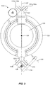
- the translation member supports 121, 123, and associated fixed and movable translation members 131a, 131b, 132a, 132b, 133a, 133b can be located diametrically opposite one another about a center of mass 106 of the translatable member 120 and attached structures (i.e., optical element 103).
- a plane 107 defined by the locations of the translation member supports 121, 123, and associated fixed and movable translation members 131a, 131b, 132a, 132b, 133a, 133b can pass through the center of mass 106.
- the plane 107 can include an optical axis of the lens 103, in this case extending perpendicular to the view in FIG. 3 through the center of mass 106.
- the fixed and movable translation members 131a, 131b, 132a, 132b, 133a, 133b can interface with the translation member supports 121, 123 at a minimal distance from the center of mass 106.
- Such an arrangement or configuration can symmetrically support the translatable member 120 and attached structures about the center of mass 106 to minimize or reduce the moments created due to dynamic loading (i.e., vibrations), which can minimize or reduce jitter of the lens thereby improving performance.
- an optical axis can be offset from the plane 107 or in any suitable orientation relative to the plane, such as to improve packaging efficiency and/or meet space constraints.
- the fixed and movable translation members 131a, 131b, 132a, 132b, 133a, 133b can comprise one or more rollers, as illustrated in FIGS. 1A-3 .
- a roller is any structure, feature, or device that rotates to facilitate relative translation of the translatable member 120 and the fixed member 110, typically of a cylindrical and/or spherical configuration, such as a wheel.
- the interface surfaces 121a, 121b, 122a, 122b, 123a, 123b can be configured to interface with rollers.
- an interface between a roller and an interface surface can be "line" contact, which can prevent or minimize yielding of the interface surface due to shock that can create localized depressions in the interface surface, thereby maintaining smooth motion and motion precision capabilities.
- a roller can include a bearing, such as a ball bearing and/or a roller bearing, which can be configured as a radial and/or a thrust bearing.
- a bearing can have an angle of misalignment that is the maximum amount an inner bearing race can go off-axis relative to an outer bearing race.
- a bearing can have an angle of misalignment between inner and outer races that can serve to maintain line contact between a roller and an interface surface. For example, manufacturing tolerances can be selected such that the angle of misalignment can be sufficient to facilitate line contact between a roller and an interface surface upon assembly and maintained during operation.
- the bearings can therefore "self-align" to maintain line contact, which can preserve smooth motion and motion precision capabilities even after high loading events, such as shock.
- the relative translation system 100 disclosed herein can be minimally affected by thermal expansion.
- temperature variations can cause misalignment due to coefficient of thermal expansion (CTE) mismatch.
- CTE coefficient of thermal expansion
- the only CTE mismatch may be due to the thickness of the bearing inner and outer races, which are small thicknesses compared to other designs. In the case of a focus cell, this can minimize boresight drift or lens misalignment over a temperature range, which can substantially maintain lens position over the temperature range.
- the relative translation system 100 can thus provide consistent, reliable, and repeatable performance over a range of temperatures and when subjected to high (i.e., shock) loads.
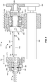
- FIG. 4 is a schematic illustration of a drive mechanism 202.
- the drive mechanism 202 can include a drive shaft 240 having a threaded portion 241.
- the drive mechanism 202 can also include a drive shaft support bearing 250 to facilitate rotation of the drive shaft 240 about a drive axis 208.
- the drive shaft support bearing 250 can be configured to support the drive shaft 240 and interface with a first structure 210, such as a fixed support structure of a relative translation system as disclosed above.
- a first structure 210 such as a fixed support structure of a relative translation system as disclosed above.
- an outer race 251 of the drive shaft support bearing 250 can be configured to interface with the first structure 210 and an inner race 252 of the drive shaft support bearing 250 can be configured to interface with a locating portion 242 of the drive shaft 240.
- the locating portion 242 and the inner race 252 can interface with one another in an interference, clearance, or slip fit.
- the drive mechanism 202 can include a drive member 260 engaged with the threaded portion 241 of the drive shaft 240.
- the drive member 260 can be configured to be fixed to a second structure 220, such as a translatable member of a relative translation system as disclosed above, to facilitate translation relative to the threaded portion 241 upon rotation of the drive shaft 240.
- the interface of the drive member 260 and the threaded portion 241 can convert rotational motion of the drive shaft 240 about the drive axis 208 to linear motion of the drive member 260 in direction 204.
- drive shaft support bearing 250 is illustrated as interfacing with a fixed structure and the drive member 260 is illustrated as being fixed to a movable structure, it should be recognized that the drive shaft support bearing 250 can interface with a movable structure and the drive member 260 can be fixed to a fixed structure.
- a position of the drive member 260 can be adjustable upon assembly relative to the second structure 220 to compensate for drive axis translation tolerance or misalignment, which occurs when a drive axis does not “line up” with a translating member and may result due to manufacturing tolerances.
- the second structure 220 can have an opening 224 to receive the drive shaft 240 that is sufficiently oversized to allow the drive member 260 to "float" for lateral adjustment and “centering" without interference between the drive shaft 240 and the second structure 220.
- the drive member 260 can then be fixed to the second structure 220 via any suitable means, such as a fastener 261, pin, rivet, weld, etc.
- an angle of misalignment of the drive shaft support bearing 250 can compensate for angular misalignment or rotational tolerances of the drive shaft, which may result due to manufacturing tolerances, such as the roundness and/or non-concentricity of drive shaft 240 features and/or a perpendicularity tolerance of the first structure 210 to bearing 250 interface.
- the drive shaft 240 can therefore be prevented from binding or increased resistance with the drive member 260 due to misalignment and/or runout tolerances of the drive shaft 240, such as rotational and/or translational tolerances, by a one-time adjustment of the drive member 260 and taking advantage of the angular misalignment of the drive shaft support bearing 250.
- This can facilitate manufacture of the drive mechanism 202 with more relaxed tolerances than would otherwise be possible, which can reduce costs.
- the drive mechanism 202 can also include a bearing 270 configured to interface with the first structure 210 proximate the drive shaft support bearing 250.
- a bearing 270 configured to interface with the first structure 210 proximate the drive shaft support bearing 250.
- an outer race 271 of the bearing 270 can be configured to interface with the first structure 210.
- the bearing 270 can have a clearance or loose slip fit for the drive shaft 240 extending through an inner race 272 of the bearing 270.
- the drive shaft 240 can have a reduced diameter portion 243 to provide the clearance or loose slip fit with the bearing 270.
- the bearing 270 may have no contact with the drive shaft 240.
- the bearings 250, 270 can each have a rolling element 253, 273, respectively, which can comprise a ball, roller, or other suitable bearing rolling element.
- the bearings 250, 270 can also be configured as radial and/or thrust bearings.
- the drive mechanism 202 can include a spring 280, such as a spring washer, configured to act on the inner race 272 of the bearing 270 to facilitate preload of the bearings 250, 270.
- the drive shaft 240 can include a spring interface feature 244 to interface with the spring 280.
- the spring interface feature 244 can comprise a locally increased diameter portion of the drive shaft 240.
- a fastener 281, such as a nut, can be threaded onto a threaded feature 245 of the drive shaft 240 to preload the spring 280 and the bearings 250, 270.
- a tool interface feature 245, such as a hole can be used to interface with a tool to resist rotation of the drive shaft while the fastener 281 is rotated to apply preload.
- the drive shaft support bearing 250 can therefore serve to locate and support the drive shaft 240 and the bearing 270 can serve to reduce rotating friction of the spring 280.
- the low friction provided by the bearing 270 for the spring 280 can provide performance benefits, such as repeatability of lens adjustment when the drive mechanism 202 is incorporated in a focus cell.
- the drive shaft 240 can have a mid portion 246 configured to provide flexibility sufficient to accommodate a misalignment and/or runout tolerances of the drive shaft 240.
- the mid portion 246 can have a length 247 and a diameter 248 configured to flex in response to forces tending to bind and/or increase friction of the threaded portion 241 and the drive member 260 while transferring torque sufficient to cause relative translation of the first and second structures 210, 220.
- the flexibility of the mid portion 246 can therefore compensate for any remaining problems due to part and/or assembly tolerances.
- the drive mechanism 202 can be configured to simply exert a drive force to cause translation of the second member 220 without providing any structural support for the second member 220.
- the second member 220 can be structurally supported and constrained for linear motion in direction 204 independent of the drive mechanism 202. This separation of the drive mechanism 202 from structural support and/or constraint of the second member 220 can provide benefits to reliability, switching speed, and motion precision over a long range of travel.
- the drive mechanism 202 can include a backlash compensation mechanism 263.
- the backlash compensation mechanism 263 can comprise a nut 264 threaded onto the threaded portion 241 and coupled to the drive member 260 via a pin 265 or other suitable fastener.
- a spring 266 between the drive member 260 and the nut 264 can preload the nut 264. Threads of the nut 264 can cooperate with threads of the drive member 260 to remove backlash with the threads of the threaded portion 241.
- the backlash compensation mechanism 263, the bearing 270, and the spring interface feature 244 can be omitted.
- the spring 280 could contact and extend between the inner race 252 of the drive shaft support bearing 250 and the drive member 260, which could preload the drive member 260, as well as the drive shaft support bearing 250, to prevent or eliminate backlash between the threads of the drive member 260 and the threaded portion 241 of the drive shaft 240.
- the drive mechanism 202 can also include a motor 290 coupled to the drive shaft 240.
- the motor 290 can be coupled to the drive shaft 240 via a drive train comprising one or more gears 291, 292, a chain, a belt, and/or a pulley.
- the drive shaft 240 can include a drive interface portion 249 to facilitate coupling with the motor 290, such as by interfacing with the gear 292.
- the motor 290 can be an electric motor or any other suitable motor for imparting torque to the drive shaft 240.
- the motor 290 can be coupled to and supported by the first structure 210.
Landscapes
- Engineering & Computer Science (AREA)
- General Engineering & Computer Science (AREA)
- Physics & Mathematics (AREA)
- Mechanical Engineering (AREA)
- General Physics & Mathematics (AREA)
- Optics & Photonics (AREA)
- Support Of The Bearing (AREA)
- Transmission Devices (AREA)
- Lens Barrels (AREA)
Claims (15)
- Relativverschiebungsanordnung, die Folgendes umfasst:ein fixiertes Stützelement (110);ein verschiebbares Element (120), das durch das fixierte Stützelement gestützt wird; undeinen Verschiebungsführungsabschnitt (130), um eine Verschiebung des verschiebbaren Elements relativ zu dem fixierten Stützelement zu ermöglichen, wobei der Verschiebungsführungsabschnitt ein fixiertes Verschiebungselement (131a, 131b, 132a, 132b, 133a) und ein bewegliches Verschiebungselement (133b) aufweist, wobei das bewegliche Verschiebungselement konfiguriert ist, um eine Vorspannung an den fixierten und beweglichen Verschiebungselementen aufrechtzuerhalten und eine Wärmeausdehnung aufzunehmen;dadurch gekennzeichnet, dassdas bewegliche Verschiebungselement mit einem Schwinghebel (134) gekoppelt ist, der drehbar mit dem fixierten Stützelement für eine Drehung um eine Achse (105) herum gekoppelt ist.
- Relativverschiebungsanordnung nach Anspruch 1, die ferner eine Feder (135) umfasst, um die Vorspannung bereitzustellen.
- Relativverschiebungsanordnung nach Anspruch 1, wobei das bewegliche Verschiebungselement durch das fixierte Stützelement beweglich gestützt wird.
- Relativverschiebungsanordnung nach Anspruch 1, wobei das bewegliche Verschiebungselement drehbar und verschiebbar durch das fixierte Stützelement gestützt wird.
- Relativverschiebungsanordnung nach Anspruch 1, die ferner mehrere fixierte Verschiebungselemente umfasst, wobei wenigstens eines der fixierten Verschiebungselemente und das bewegliche Verschiebungselement eine Rolle umfassen.
- Relativverschiebungsanordnung nach Anspruch 5, wobei wenigstens eines der fixierten Verschiebungselemente und das bewegliche Verschiebungselement ein Lager umfasst.
- Relativverschiebungsanordnung nach Anspruch 5, wobei der Verschiebungsführungsabschnitt eine Rollenübergangsstelle umfasst, um sich mit der Rolle über eine Übergangsstelle zu verbinden.
- Relativverschiebungssystem, das Folgendes umfasst:eine Relativverschiebungsanordnung nach Anspruch 1; undeinen Antriebsmechanismus (202), der konfiguriert ist, um die Verschiebung des verschiebbaren Elements relativ zu dem fixierten Stützelement zu bewirken.
- System nach Anspruch 8, wobei der Antriebsmechanismus Folgendes umfasst:eine Antriebswelle (240) mit einem Gewindeabschnitt (241);ein Lager (250), um eine Drehung der Antriebswelle zu ermöglichen, wobei das Lager konfiguriert ist, um die Antriebswelle zu stützen und sich mit dem fixierten Stützelement über eine Übergangsstelle zu verbinden; undein Antriebselement (260), das mit dem Gewindeabschnitt der Antriebswelle in Eingriff steht und konfiguriert ist, um an dem verschiebbaren Element fixiert zu sein, um die Verschiebung relativ zu dem Gewindeabschnitt bei Drehung der Antriebswelle zu ermöglichen, wobei ein Winkel, um den ein innerer Lagerring des Lagers relativ zu einem äußeren Lagerring des Lagers außerhalb der Achse verlaufen kann, um eine Drehverlagerung der Antriebswelle zu kompensieren.
- Antriebsmechanismus nach Anspruch 9, der ferner einen Flankenspielkompensationsmechanismus (263) umfasst.
- Antriebsmechanismus nach Anspruch 9, wobei das Lager ein Kugellager, ein Rollenlager, ein Radiallager, ein Schublager oder Kombinationen davon umfasst.
- Antriebsmechanismus nach Anspruch 9, das ferner Folgendes umfasst:ein zweites Lager (270), das konfiguriert ist, um sich mit dem fixierten Stützelement nahe des ersten Lagers über eine Übergangsstelle zu verbinden, wobei das zweite Lager einen Abstand für die sich dahindurch erstreckende Antriebswelle aufweist; undeine Feder (280), die konfiguriert ist, um auf einen inneren Ring des zweiten Lagers zu wirken, um die Vorspannung des ersten und des zweiten Lagers zu ermöglichen.
- Antriebsmechanismus nach Anspruch 9, wobei die Antriebswelle einen Mittelabschnitt (246) umfasst, der konfiguriert ist, um eine Flexibilität bereitzustellen, die ausreicht, um eine Verlagerung der Antriebswelle aufzunehmen.
- Antriebsmechanismus nach Anspruch 9, der ferner einen Motor (290) umfasst, der mit der Antriebswelle gekoppelt ist.
- Antriebsmechanismus nach Anspruch 14, wobei der Motor mit der Antriebswelle über ein Antriebsgetriebe gekoppelt ist.
Applications Claiming Priority (2)
| Application Number | Priority Date | Filing Date | Title |
|---|---|---|---|
| US14/446,079 US9726267B2 (en) | 2014-07-29 | 2014-07-29 | Relative translation system |
| PCT/US2015/033373 WO2016018506A1 (en) | 2014-07-29 | 2015-05-29 | Relative translation system |
Publications (2)
| Publication Number | Publication Date |
|---|---|
| EP3195039A1 EP3195039A1 (de) | 2017-07-26 |
| EP3195039B1 true EP3195039B1 (de) | 2020-04-29 |
Family
ID=53434468
Family Applications (1)
| Application Number | Title | Priority Date | Filing Date |
|---|---|---|---|
| EP15730333.0A Active EP3195039B1 (de) | 2014-07-29 | 2015-05-29 | System zur relativen übersetzung |
Country Status (4)
| Country | Link |
|---|---|
| US (3) | US9726267B2 (de) |
| EP (1) | EP3195039B1 (de) |
| IL (1) | IL250057B (de) |
| WO (1) | WO2016018506A1 (de) |
Families Citing this family (3)
| Publication number | Priority date | Publication date | Assignee | Title |
|---|---|---|---|---|
| DE102011117723B4 (de) * | 2011-11-07 | 2015-01-08 | Thyssenkrupp Presta Aktiengesellschaft | Kugelgewindetrieb mit Lagerausgleich |
| CN105276141B (zh) * | 2014-07-16 | 2020-08-21 | 力纳克传动系统(深圳)有限公司 | 线性致动器 |
| DE102015204071B4 (de) * | 2015-03-06 | 2017-05-24 | Schaeffler Technologies AG & Co. KG | Linearer Stellantrieb und Verfahren zur Montage eines Stellantriebs |
Family Cites Families (62)
| Publication number | Priority date | Publication date | Assignee | Title |
|---|---|---|---|---|
| AT278287B (de) * | 1965-12-13 | 1970-01-26 | Lets Aufzug Etablissement | Aufzug mit Schraubenantrieb |
| US3578829A (en) * | 1968-11-26 | 1971-05-18 | Matsushita Electric Industrial Co Ltd | Bottom bracket for bicycle |
| US3670583A (en) * | 1970-10-19 | 1972-06-20 | Overton Gear And Tool Corp | Long span screw and nut drives |
| JPS5148066A (en) * | 1974-10-24 | 1976-04-24 | Nomura Takayuki | Idotaino kafukaanzensochi |
| US3977269A (en) * | 1975-05-05 | 1976-08-31 | Universal Thread Grinding Company | Anti-backlash, self-aligning nut |
| GB1592491A (en) * | 1977-02-17 | 1981-07-08 | British Aerospace | Bearing assemblies |
| US4131029A (en) * | 1977-06-10 | 1978-12-26 | Eocom Corporation | Gimballed coupling for lead screw and nut assembly |
| US4438986A (en) * | 1981-03-13 | 1984-03-27 | Hiroshi Teramachi | Ball screw assembly containing a ball spline unit for exact slow feed and power transmission mechanism comprising said ball screw assembly |
| US4415941A (en) | 1981-06-29 | 1983-11-15 | Atasi Corporation | Linear actuator for memory storage device |
| JPS61267972A (ja) | 1985-05-22 | 1986-11-27 | Hitachi Ltd | キヤリツジの支持構造 |
| JPH0351546Y2 (de) * | 1986-01-07 | 1991-11-06 | ||
| US4787260A (en) | 1987-04-20 | 1988-11-29 | Cincinnati Milacron Inc. | Self-alignment device for ballscrew arrangement |
| US4853808A (en) | 1987-10-30 | 1989-08-01 | Cardiff Technology Inc. | Linear actuator for disc drive |
| JPH0386238U (de) * | 1989-12-25 | 1991-08-30 | ||
| US5331861A (en) * | 1990-06-04 | 1994-07-26 | Benjamin Joffe | Rotating drive magnetically coupled for producing linear motion |
| US6093989A (en) * | 1990-06-04 | 2000-07-25 | Joffe; Benjamin | Advanced magnetically-stabilized couplings and bearings, for use in mechanical drives |
| US5425282A (en) * | 1991-10-21 | 1995-06-20 | Luigs; Willi | Manipulator |
| DE69432192T2 (de) * | 1993-10-12 | 2003-12-04 | Smc K.K., Tokio/Tokyo | Linearantrieb |
| US5448438A (en) * | 1993-11-09 | 1995-09-05 | Quantum Corporation | Head actuator having spring loaded split nut |
| EP0698744A4 (de) * | 1994-03-10 | 1996-07-31 | Enomoto Co Ltd | Schiebestab |
| DE4411516B4 (de) | 1994-04-02 | 2005-12-22 | Carl Zeiss Ag | Spielfreies Kurvengetriebe |
| DE19636272A1 (de) * | 1996-09-06 | 1998-03-12 | Star Gmbh | Linearführungseinrichtung |
| US6142032A (en) * | 1998-01-30 | 2000-11-07 | Creager; Wesley Carl | Adjustable anti-backlash nut assembly |
| US6000308A (en) * | 1998-03-23 | 1999-12-14 | Flow International Corporation | Screw drive method and apparatus |
| DE59904959D1 (de) * | 1998-05-20 | 2003-05-15 | Continental Teves Ag & Co Ohg | Befestigung eines lenkwinkelsensors |
| US6119541A (en) * | 1999-03-25 | 2000-09-19 | Micron Electronics, Inc. | Methods for adjusting a lead screw nut and a nut for adjustably engaging a lead screw |
| US6371681B1 (en) * | 1999-09-20 | 2002-04-16 | Bell Helicopter Textron Inc. | Anti-rotation clip |
| US7448134B2 (en) * | 2001-04-06 | 2008-11-11 | Smc Kabushiki Kaisha | Method for producing actuator having guide-equipped frame |
| US7293626B2 (en) * | 2001-08-01 | 2007-11-13 | Delphi Technologies, Inc. | Apparatus and method for steering a vehicle |
| JP2004028169A (ja) * | 2002-06-24 | 2004-01-29 | Smc Corp | 電動アクチュエータ |
| US6931960B1 (en) * | 2002-10-15 | 2005-08-23 | Raytheon Company | Leadscrew mechanical drive with differential leadscrew follower structure |
| JP4107326B2 (ja) * | 2003-04-18 | 2008-06-25 | 株式会社ジェイテクト | 電動パワーステアリング装置 |
| JP4716679B2 (ja) * | 2003-06-25 | 2011-07-06 | 日本精工株式会社 | ウォーム減速機及び電動式パワーステアリング装置 |
| JP2006184543A (ja) * | 2004-12-27 | 2006-07-13 | Sony Corp | 組レンズの組立て方法、この方法によって組立てられた組レンズ、および撮像装置 |
| US7531773B2 (en) * | 2005-09-08 | 2009-05-12 | Flextronics Ap, Llc | Auto-focus and zoom module having a lead screw with its rotation results in translation of an optics group |
| US20070295128A1 (en) * | 2006-05-19 | 2007-12-27 | Erikson Keith W | Lead screw actuator with torsional anti-backlash nut |
| JP4045290B2 (ja) | 2006-05-19 | 2008-02-13 | シャープ株式会社 | 撮像装置 |
| DE102007030445B4 (de) * | 2006-08-25 | 2019-05-16 | Adient Luxembourg Holding S.À R.L. | Stellantrieb eines Kraftfahrzeugsitzes |
| KR100843403B1 (ko) * | 2006-12-19 | 2008-07-03 | 삼성전기주식회사 | 렌즈 이송장치 |
| JP4973227B2 (ja) | 2007-02-16 | 2012-07-11 | 株式会社ニコン | 駆動装置、レンズ鏡筒及びカメラ |
| US7992456B2 (en) * | 2007-12-10 | 2011-08-09 | Pacific Bearing Company | Anti-backlash nut, lead screw assembly and method |
| JP5117206B2 (ja) | 2008-01-30 | 2013-01-16 | 株式会社タムロン | ボルト軸とナットとの組合せ構造からなる摺動部材 |
| US20090277292A1 (en) * | 2008-04-30 | 2009-11-12 | Steven Charles Quarre | Precision drive mechanism for long-travel microscopy stage |
| PL2344372T3 (pl) * | 2008-09-19 | 2014-07-31 | Gm Global Tech Operations Llc | Mechanizm przekształcający ruch obrotowy w liniowy wyposażony w element izolujący |
| JP5180799B2 (ja) * | 2008-12-10 | 2013-04-10 | 日本トムソン株式会社 | アクチュエータ |
| TWI397763B (zh) * | 2009-03-16 | 2013-06-01 | Asia Optical Co Inc | The transmission of optical equipment |
| DE102009016187B4 (de) * | 2009-04-03 | 2020-11-05 | Schaeffler Technologies AG & Co. KG | Lager für eine Vorrichtung zur Erzeugung eines Schwenkmoments |
| TWI394905B (zh) * | 2009-08-28 | 2013-05-01 | Ind Tech Res Inst | 進給驅動機構及其連接組件 |
| JP5397236B2 (ja) * | 2010-01-18 | 2014-01-22 | Smc株式会社 | 送りねじ機構 |
| JP5643957B2 (ja) * | 2010-02-17 | 2014-12-24 | 石川県 | 圧電アクチュエータ機構 |
| FR2970464B1 (fr) * | 2011-01-19 | 2014-10-17 | Goodrich Actuation Systems Sas | Perfectionnements aux actionneurs de commande de vol a ecrou secondaire |
| US9010205B2 (en) * | 2011-01-20 | 2015-04-21 | Pacific Bearing Company | Linear slide having integral carriage and nut assembly |
| WO2012120670A1 (ja) * | 2011-03-09 | 2012-09-13 | 株式会社日立製作所 | リニアアクチュエータ |
| CA2842314A1 (en) * | 2011-07-18 | 2013-01-24 | Nook Industries, Inc. | No-lash nut assembly |
| EP2746619B1 (de) * | 2011-08-17 | 2019-04-24 | NSK Ltd. | Kugelgewindetrieb und montageverfahren dafür |
| JP2013071679A (ja) * | 2011-09-28 | 2013-04-22 | Showa Corp | 電動パワーステアリング装置 |
| US9303742B2 (en) * | 2011-11-28 | 2016-04-05 | Pacific Bearing Company | Inverted spline rail system |
| US9170106B2 (en) | 2012-04-19 | 2015-10-27 | Raytheon Corporation | Shock-resistant device and method |
| DE202012003946U1 (de) * | 2012-04-20 | 2012-05-15 | Igus Gmbh | Spindelmutter mit Schwenkkopf |
| KR101313089B1 (ko) * | 2012-09-27 | 2013-10-01 | 이종기 | 스크류 조립체 |
| EP3670941A1 (de) * | 2018-12-20 | 2020-06-24 | Goodrich Actuation Systems Limited | Vorgespannte lageranordnung |
| CN111720510A (zh) * | 2020-05-22 | 2020-09-29 | 福建省黑石精密机械有限公司 | 一种机床高精度运动轴及工作方法 |
-
2014
- 2014-07-29 US US14/446,079 patent/US9726267B2/en active Active
-
2015
- 2015-05-29 WO PCT/US2015/033373 patent/WO2016018506A1/en not_active Ceased
- 2015-05-29 EP EP15730333.0A patent/EP3195039B1/de active Active
-
2017
- 2017-01-11 IL IL250057A patent/IL250057B/en unknown
- 2017-08-01 US US15/666,285 patent/US10914364B2/en active Active
-
2021
- 2021-02-09 US US17/171,980 patent/US20210164545A1/en not_active Abandoned
Non-Patent Citations (1)
| Title |
|---|
| None * |
Also Published As
| Publication number | Publication date |
|---|---|
| US9726267B2 (en) | 2017-08-08 |
| US20210164545A1 (en) | 2021-06-03 |
| IL250057A0 (en) | 2017-03-30 |
| WO2016018506A1 (en) | 2016-02-04 |
| US10914364B2 (en) | 2021-02-09 |
| IL250057B (en) | 2021-07-29 |
| US20160033017A1 (en) | 2016-02-04 |
| EP3195039A1 (de) | 2017-07-26 |
| US20170343086A1 (en) | 2017-11-30 |
Similar Documents
| Publication | Publication Date | Title |
|---|---|---|
| US20210164545A1 (en) | Relative Translation System | |
| US10294989B2 (en) | Linear motion guide device | |
| JP2016057470A (ja) | 直線駆動装置 | |
| KR101218772B1 (ko) | 유연기구를 이용한 회전 오차 보상 스테이지 | |
| CN101474758A (zh) | 具有混联导轨结合部的宏微驱动精密进给系统 | |
| CN110104221A (zh) | 一种通用在轨补加接口装置 | |
| CN112081822A (zh) | 一种新型导轨刚柔耦合平台 | |
| CN104400414B (zh) | 基于密珠滚动支承的航空发动机装配测量一体化调心方法与装置 | |
| US20090277292A1 (en) | Precision drive mechanism for long-travel microscopy stage | |
| JP4992182B2 (ja) | 回転機構付軸方向微動装置 | |
| CN104400374B (zh) | 用于航空发动机转静子装配测量的双框共面导向式调心方法与装置 | |
| CN110002009B (zh) | 一种被动柔顺组件及在轨补加接口装置 | |
| JP2005221044A (ja) | 角度調整装置 | |
| US7948715B2 (en) | Head positioning assembly | |
| US20230150043A1 (en) | Actively preloaded drive-guideway system | |
| JP5067487B2 (ja) | 位置決め装置 | |
| JP5273270B2 (ja) | 回転機構付軸方向微動機構およびそれを用いた位置決め装置 | |
| KR102799821B1 (ko) | 고니오 스테이지 | |
| CN223854773U (zh) | 多动子驱动模组 | |
| US7765891B2 (en) | Robotic compliance mechanism | |
| CN224074089U (zh) | 一种全向平面恒力浮动装置 | |
| CN114227235B (zh) | 一种全自动柔性切换转股 | |
| CN104440809B (zh) | 回复力恒定式航空发动机装配用平面二维调整装置 | |
| US20250018565A1 (en) | Apparatus, apparatus control method, article manufacturing method, apparatus assembly method, robot, automobile, and recording medium | |
| US20250198488A1 (en) | Guidance system |
Legal Events
| Date | Code | Title | Description |
|---|---|---|---|
| STAA | Information on the status of an ep patent application or granted ep patent |
Free format text: STATUS: THE INTERNATIONAL PUBLICATION HAS BEEN MADE |
|
| PUAI | Public reference made under article 153(3) epc to a published international application that has entered the european phase |
Free format text: ORIGINAL CODE: 0009012 |
|
| STAA | Information on the status of an ep patent application or granted ep patent |
Free format text: STATUS: REQUEST FOR EXAMINATION WAS MADE |
|
| 17P | Request for examination filed |
Effective date: 20170228 |
|
| AK | Designated contracting states |
Kind code of ref document: A1 Designated state(s): AL AT BE BG CH CY CZ DE DK EE ES FI FR GB GR HR HU IE IS IT LI LT LU LV MC MK MT NL NO PL PT RO RS SE SI SK SM TR |
|
| AX | Request for extension of the european patent |
Extension state: BA ME |
|
| DAV | Request for validation of the european patent (deleted) | ||
| DAX | Request for extension of the european patent (deleted) | ||
| GRAP | Despatch of communication of intention to grant a patent |
Free format text: ORIGINAL CODE: EPIDOSNIGR1 |
|
| STAA | Information on the status of an ep patent application or granted ep patent |
Free format text: STATUS: GRANT OF PATENT IS INTENDED |
|
| INTG | Intention to grant announced |
Effective date: 20191209 |
|
| GRAS | Grant fee paid |
Free format text: ORIGINAL CODE: EPIDOSNIGR3 |
|
| GRAA | (expected) grant |
Free format text: ORIGINAL CODE: 0009210 |
|
| STAA | Information on the status of an ep patent application or granted ep patent |
Free format text: STATUS: THE PATENT HAS BEEN GRANTED |
|
| AK | Designated contracting states |
Kind code of ref document: B1 Designated state(s): AL AT BE BG CH CY CZ DE DK EE ES FI FR GB GR HR HU IE IS IT LI LT LU LV MC MK MT NL NO PL PT RO RS SE SI SK SM TR |
|
| REG | Reference to a national code |
Ref country code: GB Ref legal event code: FG4D |
|
| REG | Reference to a national code |
Ref country code: CH Ref legal event code: EP |
|
| REG | Reference to a national code |
Ref country code: AT Ref legal event code: REF Ref document number: 1264175 Country of ref document: AT Kind code of ref document: T Effective date: 20200515 |
|
| REG | Reference to a national code |
Ref country code: DE Ref legal event code: R096 Ref document number: 602015051620 Country of ref document: DE |
|
| REG | Reference to a national code |
Ref country code: IE Ref legal event code: FG4D |
|
| REG | Reference to a national code |
Ref country code: NL Ref legal event code: MP Effective date: 20200429 |
|
| REG | Reference to a national code |
Ref country code: LT Ref legal event code: MG4D |
|
| PG25 | Lapsed in a contracting state [announced via postgrant information from national office to epo] |
Ref country code: IS Free format text: LAPSE BECAUSE OF FAILURE TO SUBMIT A TRANSLATION OF THE DESCRIPTION OR TO PAY THE FEE WITHIN THE PRESCRIBED TIME-LIMIT Effective date: 20200829 Ref country code: SE Free format text: LAPSE BECAUSE OF FAILURE TO SUBMIT A TRANSLATION OF THE DESCRIPTION OR TO PAY THE FEE WITHIN THE PRESCRIBED TIME-LIMIT Effective date: 20200429 Ref country code: PT Free format text: LAPSE BECAUSE OF FAILURE TO SUBMIT A TRANSLATION OF THE DESCRIPTION OR TO PAY THE FEE WITHIN THE PRESCRIBED TIME-LIMIT Effective date: 20200831 Ref country code: NO Free format text: LAPSE BECAUSE OF FAILURE TO SUBMIT A TRANSLATION OF THE DESCRIPTION OR TO PAY THE FEE WITHIN THE PRESCRIBED TIME-LIMIT Effective date: 20200729 Ref country code: LT Free format text: LAPSE BECAUSE OF FAILURE TO SUBMIT A TRANSLATION OF THE DESCRIPTION OR TO PAY THE FEE WITHIN THE PRESCRIBED TIME-LIMIT Effective date: 20200429 Ref country code: FI Free format text: LAPSE BECAUSE OF FAILURE TO SUBMIT A TRANSLATION OF THE DESCRIPTION OR TO PAY THE FEE WITHIN THE PRESCRIBED TIME-LIMIT Effective date: 20200429 Ref country code: GR Free format text: LAPSE BECAUSE OF FAILURE TO SUBMIT A TRANSLATION OF THE DESCRIPTION OR TO PAY THE FEE WITHIN THE PRESCRIBED TIME-LIMIT Effective date: 20200730 |
|
| REG | Reference to a national code |
Ref country code: AT Ref legal event code: MK05 Ref document number: 1264175 Country of ref document: AT Kind code of ref document: T Effective date: 20200429 |
|
| PG25 | Lapsed in a contracting state [announced via postgrant information from national office to epo] |
Ref country code: LV Free format text: LAPSE BECAUSE OF FAILURE TO SUBMIT A TRANSLATION OF THE DESCRIPTION OR TO PAY THE FEE WITHIN THE PRESCRIBED TIME-LIMIT Effective date: 20200429 Ref country code: HR Free format text: LAPSE BECAUSE OF FAILURE TO SUBMIT A TRANSLATION OF THE DESCRIPTION OR TO PAY THE FEE WITHIN THE PRESCRIBED TIME-LIMIT Effective date: 20200429 Ref country code: RS Free format text: LAPSE BECAUSE OF FAILURE TO SUBMIT A TRANSLATION OF THE DESCRIPTION OR TO PAY THE FEE WITHIN THE PRESCRIBED TIME-LIMIT Effective date: 20200429 Ref country code: BG Free format text: LAPSE BECAUSE OF FAILURE TO SUBMIT A TRANSLATION OF THE DESCRIPTION OR TO PAY THE FEE WITHIN THE PRESCRIBED TIME-LIMIT Effective date: 20200729 |
|
| PG25 | Lapsed in a contracting state [announced via postgrant information from national office to epo] |
Ref country code: AL Free format text: LAPSE BECAUSE OF FAILURE TO SUBMIT A TRANSLATION OF THE DESCRIPTION OR TO PAY THE FEE WITHIN THE PRESCRIBED TIME-LIMIT Effective date: 20200429 Ref country code: NL Free format text: LAPSE BECAUSE OF FAILURE TO SUBMIT A TRANSLATION OF THE DESCRIPTION OR TO PAY THE FEE WITHIN THE PRESCRIBED TIME-LIMIT Effective date: 20200429 |
|
| PG25 | Lapsed in a contracting state [announced via postgrant information from national office to epo] |
Ref country code: CH Free format text: LAPSE BECAUSE OF NON-PAYMENT OF DUE FEES Effective date: 20200531 Ref country code: SM Free format text: LAPSE BECAUSE OF FAILURE TO SUBMIT A TRANSLATION OF THE DESCRIPTION OR TO PAY THE FEE WITHIN THE PRESCRIBED TIME-LIMIT Effective date: 20200429 Ref country code: MC Free format text: LAPSE BECAUSE OF FAILURE TO SUBMIT A TRANSLATION OF THE DESCRIPTION OR TO PAY THE FEE WITHIN THE PRESCRIBED TIME-LIMIT Effective date: 20200429 Ref country code: ES Free format text: LAPSE BECAUSE OF FAILURE TO SUBMIT A TRANSLATION OF THE DESCRIPTION OR TO PAY THE FEE WITHIN THE PRESCRIBED TIME-LIMIT Effective date: 20200429 Ref country code: DK Free format text: LAPSE BECAUSE OF FAILURE TO SUBMIT A TRANSLATION OF THE DESCRIPTION OR TO PAY THE FEE WITHIN THE PRESCRIBED TIME-LIMIT Effective date: 20200429 Ref country code: AT Free format text: LAPSE BECAUSE OF FAILURE TO SUBMIT A TRANSLATION OF THE DESCRIPTION OR TO PAY THE FEE WITHIN THE PRESCRIBED TIME-LIMIT Effective date: 20200429 Ref country code: LI Free format text: LAPSE BECAUSE OF NON-PAYMENT OF DUE FEES Effective date: 20200531 Ref country code: CZ Free format text: LAPSE BECAUSE OF FAILURE TO SUBMIT A TRANSLATION OF THE DESCRIPTION OR TO PAY THE FEE WITHIN THE PRESCRIBED TIME-LIMIT Effective date: 20200429 Ref country code: IT Free format text: LAPSE BECAUSE OF FAILURE TO SUBMIT A TRANSLATION OF THE DESCRIPTION OR TO PAY THE FEE WITHIN THE PRESCRIBED TIME-LIMIT Effective date: 20200429 Ref country code: RO Free format text: LAPSE BECAUSE OF FAILURE TO SUBMIT A TRANSLATION OF THE DESCRIPTION OR TO PAY THE FEE WITHIN THE PRESCRIBED TIME-LIMIT Effective date: 20200429 Ref country code: EE Free format text: LAPSE BECAUSE OF FAILURE TO SUBMIT A TRANSLATION OF THE DESCRIPTION OR TO PAY THE FEE WITHIN THE PRESCRIBED TIME-LIMIT Effective date: 20200429 |
|
| REG | Reference to a national code |
Ref country code: DE Ref legal event code: R097 Ref document number: 602015051620 Country of ref document: DE |
|
| PG25 | Lapsed in a contracting state [announced via postgrant information from national office to epo] |
Ref country code: PL Free format text: LAPSE BECAUSE OF FAILURE TO SUBMIT A TRANSLATION OF THE DESCRIPTION OR TO PAY THE FEE WITHIN THE PRESCRIBED TIME-LIMIT Effective date: 20200429 Ref country code: SK Free format text: LAPSE BECAUSE OF FAILURE TO SUBMIT A TRANSLATION OF THE DESCRIPTION OR TO PAY THE FEE WITHIN THE PRESCRIBED TIME-LIMIT Effective date: 20200429 |
|
| PLBE | No opposition filed within time limit |
Free format text: ORIGINAL CODE: 0009261 |
|
| STAA | Information on the status of an ep patent application or granted ep patent |
Free format text: STATUS: NO OPPOSITION FILED WITHIN TIME LIMIT |
|
| REG | Reference to a national code |
Ref country code: BE Ref legal event code: MM Effective date: 20200531 |
|
| PG25 | Lapsed in a contracting state [announced via postgrant information from national office to epo] |
Ref country code: LU Free format text: LAPSE BECAUSE OF NON-PAYMENT OF DUE FEES Effective date: 20200529 |
|
| 26N | No opposition filed |
Effective date: 20210201 |
|
| PG25 | Lapsed in a contracting state [announced via postgrant information from national office to epo] |
Ref country code: IE Free format text: LAPSE BECAUSE OF NON-PAYMENT OF DUE FEES Effective date: 20200529 |
|
| PG25 | Lapsed in a contracting state [announced via postgrant information from national office to epo] |
Ref country code: BE Free format text: LAPSE BECAUSE OF NON-PAYMENT OF DUE FEES Effective date: 20200531 Ref country code: SI Free format text: LAPSE BECAUSE OF FAILURE TO SUBMIT A TRANSLATION OF THE DESCRIPTION OR TO PAY THE FEE WITHIN THE PRESCRIBED TIME-LIMIT Effective date: 20200429 |
|
| PG25 | Lapsed in a contracting state [announced via postgrant information from national office to epo] |
Ref country code: TR Free format text: LAPSE BECAUSE OF FAILURE TO SUBMIT A TRANSLATION OF THE DESCRIPTION OR TO PAY THE FEE WITHIN THE PRESCRIBED TIME-LIMIT Effective date: 20200429 Ref country code: MT Free format text: LAPSE BECAUSE OF FAILURE TO SUBMIT A TRANSLATION OF THE DESCRIPTION OR TO PAY THE FEE WITHIN THE PRESCRIBED TIME-LIMIT Effective date: 20200429 Ref country code: CY Free format text: LAPSE BECAUSE OF FAILURE TO SUBMIT A TRANSLATION OF THE DESCRIPTION OR TO PAY THE FEE WITHIN THE PRESCRIBED TIME-LIMIT Effective date: 20200429 |
|
| PG25 | Lapsed in a contracting state [announced via postgrant information from national office to epo] |
Ref country code: MK Free format text: LAPSE BECAUSE OF FAILURE TO SUBMIT A TRANSLATION OF THE DESCRIPTION OR TO PAY THE FEE WITHIN THE PRESCRIBED TIME-LIMIT Effective date: 20200429 |
|
| P01 | Opt-out of the competence of the unified patent court (upc) registered |
Effective date: 20230530 |
|
| PGFP | Annual fee paid to national office [announced via postgrant information from national office to epo] |
Ref country code: DE Payment date: 20250423 Year of fee payment: 11 |
|
| PGFP | Annual fee paid to national office [announced via postgrant information from national office to epo] |
Ref country code: GB Payment date: 20250423 Year of fee payment: 11 |
|
| PGFP | Annual fee paid to national office [announced via postgrant information from national office to epo] |
Ref country code: FR Payment date: 20250424 Year of fee payment: 11 |