EP3192757A1 - Ablagevorrichtung für flache güter - Google Patents
Ablagevorrichtung für flache güter Download PDFInfo
- Publication number
- EP3192757A1 EP3192757A1 EP16202399.8A EP16202399A EP3192757A1 EP 3192757 A1 EP3192757 A1 EP 3192757A1 EP 16202399 A EP16202399 A EP 16202399A EP 3192757 A1 EP3192757 A1 EP 3192757A1
- Authority
- EP
- European Patent Office
- Prior art keywords
- receiving plate
- storage device
- längsausrichtwand
- angle
- edge
- Prior art date
- Legal status (The legal status is an assumption and is not a legal conclusion. Google has not performed a legal analysis and makes no representation as to the accuracy of the status listed.)
- Granted
Links
Images

Classifications
-
- B—PERFORMING OPERATIONS; TRANSPORTING
- B65—CONVEYING; PACKING; STORING; HANDLING THIN OR FILAMENTARY MATERIAL
- B65H—HANDLING THIN OR FILAMENTARY MATERIAL, e.g. SHEETS, WEBS, CABLES
- B65H31/00—Pile receivers
- B65H31/02—Pile receivers with stationary end support against which pile accumulates
-
- B—PERFORMING OPERATIONS; TRANSPORTING
- B65—CONVEYING; PACKING; STORING; HANDLING THIN OR FILAMENTARY MATERIAL
- B65H—HANDLING THIN OR FILAMENTARY MATERIAL, e.g. SHEETS, WEBS, CABLES
- B65H31/00—Pile receivers
- B65H31/22—Pile receivers removable or interchangeable
-
- B—PERFORMING OPERATIONS; TRANSPORTING
- B65—CONVEYING; PACKING; STORING; HANDLING THIN OR FILAMENTARY MATERIAL
- B65H—HANDLING THIN OR FILAMENTARY MATERIAL, e.g. SHEETS, WEBS, CABLES
- B65H31/00—Pile receivers
- B65H31/34—Apparatus for squaring-up piled articles
-
- G—PHYSICS
- G07—CHECKING-DEVICES
- G07B—TICKET-ISSUING APPARATUS; FARE-REGISTERING APPARATUS; FRANKING APPARATUS
- G07B17/00—Franking apparatus
- G07B17/00185—Details internally of apparatus in a franking system, e.g. franking machine at customer or apparatus at post office
- G07B17/00193—Constructional details of apparatus in a franking system
-
- B—PERFORMING OPERATIONS; TRANSPORTING
- B65—CONVEYING; PACKING; STORING; HANDLING THIN OR FILAMENTARY MATERIAL
- B65H—HANDLING THIN OR FILAMENTARY MATERIAL, e.g. SHEETS, WEBS, CABLES
- B65H2301/00—Handling processes for sheets or webs
- B65H2301/40—Type of handling process
- B65H2301/42—Piling, depiling, handling piles
- B65H2301/421—Forming a pile
- B65H2301/4212—Forming a pile of articles substantially horizontal
-
- B—PERFORMING OPERATIONS; TRANSPORTING
- B65—CONVEYING; PACKING; STORING; HANDLING THIN OR FILAMENTARY MATERIAL
- B65H—HANDLING THIN OR FILAMENTARY MATERIAL, e.g. SHEETS, WEBS, CABLES
- B65H2301/00—Handling processes for sheets or webs
- B65H2301/40—Type of handling process
- B65H2301/42—Piling, depiling, handling piles
- B65H2301/422—Handling piles, sets or stacks of articles
- B65H2301/4225—Handling piles, sets or stacks of articles in or on special supports
- B65H2301/42254—Boxes; Cassettes; Containers
-
- B—PERFORMING OPERATIONS; TRANSPORTING
- B65—CONVEYING; PACKING; STORING; HANDLING THIN OR FILAMENTARY MATERIAL
- B65H—HANDLING THIN OR FILAMENTARY MATERIAL, e.g. SHEETS, WEBS, CABLES
- B65H2404/00—Parts for transporting or guiding the handled material
- B65H2404/50—Surface of the elements in contact with the forwarded or guided material
- B65H2404/51—Cross section, i.e. section perpendicular to the direction of displacement
- B65H2404/513—Cross section, i.e. section perpendicular to the direction of displacement with limited number of active areas
- B65H2404/5131—Cross section, i.e. section perpendicular to the direction of displacement with limited number of active areas saw profile
-
- B—PERFORMING OPERATIONS; TRANSPORTING
- B65—CONVEYING; PACKING; STORING; HANDLING THIN OR FILAMENTARY MATERIAL
- B65H—HANDLING THIN OR FILAMENTARY MATERIAL, e.g. SHEETS, WEBS, CABLES
- B65H2405/00—Parts for holding the handled material
- B65H2405/10—Cassettes, holders, bins, decks, trays, supports or magazines for sheets stacked substantially horizontally
- B65H2405/11—Parts and details thereof
- B65H2405/111—Bottom
- B65H2405/1115—Bottom with surface inclined, e.g. in width-wise direction
-
- B—PERFORMING OPERATIONS; TRANSPORTING
- B65—CONVEYING; PACKING; STORING; HANDLING THIN OR FILAMENTARY MATERIAL
- B65H—HANDLING THIN OR FILAMENTARY MATERIAL, e.g. SHEETS, WEBS, CABLES
- B65H2405/00—Parts for holding the handled material
- B65H2405/10—Cassettes, holders, bins, decks, trays, supports or magazines for sheets stacked substantially horizontally
- B65H2405/11—Parts and details thereof
- B65H2405/111—Bottom
- B65H2405/1115—Bottom with surface inclined, e.g. in width-wise direction
- B65H2405/11152—Bottom with surface inclined, e.g. in width-wise direction with surface inclined downwardly in transport direction
-
- B—PERFORMING OPERATIONS; TRANSPORTING
- B65—CONVEYING; PACKING; STORING; HANDLING THIN OR FILAMENTARY MATERIAL
- B65H—HANDLING THIN OR FILAMENTARY MATERIAL, e.g. SHEETS, WEBS, CABLES
- B65H2405/00—Parts for holding the handled material
- B65H2405/10—Cassettes, holders, bins, decks, trays, supports or magazines for sheets stacked substantially horizontally
- B65H2405/11—Parts and details thereof
- B65H2405/114—Side, i.e. portion parallel to the feeding / delivering direction
-
- B—PERFORMING OPERATIONS; TRANSPORTING
- B65—CONVEYING; PACKING; STORING; HANDLING THIN OR FILAMENTARY MATERIAL
- B65H—HANDLING THIN OR FILAMENTARY MATERIAL, e.g. SHEETS, WEBS, CABLES
- B65H2405/00—Parts for holding the handled material
- B65H2405/10—Cassettes, holders, bins, decks, trays, supports or magazines for sheets stacked substantially horizontally
- B65H2405/11—Parts and details thereof
- B65H2405/114—Side, i.e. portion parallel to the feeding / delivering direction
- B65H2405/1142—Projections or the like in surface contact with handled material
-
- B—PERFORMING OPERATIONS; TRANSPORTING
- B65—CONVEYING; PACKING; STORING; HANDLING THIN OR FILAMENTARY MATERIAL
- B65H—HANDLING THIN OR FILAMENTARY MATERIAL, e.g. SHEETS, WEBS, CABLES
- B65H2601/00—Problem to be solved or advantage achieved
- B65H2601/20—Avoiding or preventing undesirable effects
- B65H2601/25—Damages to handled material
- B65H2601/252—Collapsing, e.g. of piles
-
- B—PERFORMING OPERATIONS; TRANSPORTING
- B65—CONVEYING; PACKING; STORING; HANDLING THIN OR FILAMENTARY MATERIAL
- B65H—HANDLING THIN OR FILAMENTARY MATERIAL, e.g. SHEETS, WEBS, CABLES
- B65H2701/00—Handled material; Storage means
- B65H2701/10—Handled articles or webs
- B65H2701/19—Specific article or web
- B65H2701/1916—Envelopes and articles of mail
-
- B—PERFORMING OPERATIONS; TRANSPORTING
- B65—CONVEYING; PACKING; STORING; HANDLING THIN OR FILAMENTARY MATERIAL
- B65H—HANDLING THIN OR FILAMENTARY MATERIAL, e.g. SHEETS, WEBS, CABLES
- B65H2801/00—Application field
- B65H2801/78—Mailing systems
Definitions
- the invention relates to a storage device for flat goods according to the preamble of claim 1.
- Such storage devices are used for example in good processing systems or as the last station of a postal road.
- a postal road of a franking system consists of individual juxtaposed mail processing stations and the flat goods are mail pieces.
- a landing station can be set up, which is used to create individual or stacked mail pieces, which are transported post-downstream through further stations to the end of the post road to the storage device.
- a stack of mail pieces of different format (mixed mail) which was applied to the docking station, is isolated in the postal road by means of a separating device immediately following in the direction of transport of a feed station, since further subsequent mail processing stations need individually supplied mail pieces.
- the flat product depositing device is intended for use in connection with previously arranged good processing devices, for example mail processing stations in connection with franking, addressing machines and other mail processing stations.
- Mixed mail should also be understood to mean format-like mail pieces which vary in height and width within limits of up to 10%, for example letters of the formats B6 (12.5 x 17.6 cm) and C6 (11.4 x 16.2 cm).
- a stack When referring to a stack below, it is meant a stack of letters, a stack of postcards, a stack of mailpieces, or other stacked goods, which may be singulated and fed to the side.
- a storage device for a larger amount of stacked mail pieces is to be understood by the term stack box.
- Such a box-shaped box of small dimensions for example, from the Japanese patent application JP 2000063026 A previously known.
- the bottom of the box is not inclined.
- a front side panel opens like a door to retrieve the stack of mailpieces, such as postcards.
- postcards of the same format does not arise the problem, as for postcards of different formats, namely that a high stack threatens to tip over.
- the patent shows US 6,648,284 B2 an adjustment insert block within a goods storage trough having a bottom surface and a plurality of upstanding side walls connected to the bottom surface of the goods storage trough.
- the trim insert block has a double inclined surface which effects alignment of the stack of mail pieces at a corner of the goods storage pan.
- JP 2002234659 A has two wedge-shaped slopes at the bottom of a box whose surface is inclined back to a guide wall for receiving paper sheets.
- a stop wall forms a downstream end of the box.
- a guide wall projects into the area of trajectories of the paper sheets, in contrast to the beginning of the box.
- a sheet of paper on a maximum trajectory therefore strikes the guide wall first and then falls onto the slopes at the bottom of the box.
- a pressure medium collector that includes a guide surface having an inlet edge and an exit edge, wherein the guide surface slopes downwardly from the inlet edge to the exit edge, such that when a printer releases a pressure medium, which gravitates to the guide surface via the exit edge falls down and is moved with a leading edge of the printed medium within a range of trajectories, each trajectory having a downward and lateral component.
- An abutment on the back of the pressure accumulator area can be a lateral movement block the print media so that such printed media are stored on a support surface against the fence to form a stack.
- the aforesaid range of trajectories includes a maximum trajectory in which the leading edge of the print medium is capable of first contacting the stop to only then contact a print medium already on the support surface.
- the support surface is only slightly inclined in the transport direction downwards.
- the print medium collector is well suited for fixed length sheet printing media, but unsuitable as a collector of mail pieces of a different format (mixed mail).
- a device for receiving mailpieces is known to receive the ejected via an exit slot of a folding and inserting mailpieces.
- the ejected mail items accumulate, which will strike a stop wall.
- Two sidewalls and one wall are designed to realign these mail pieces once dropped onto the support plate, the wall having coupling means for allowing the receptacle to be slipped onto the front feet of a folding and inserting machine.
- the pick-up device is not completely satisfactory because, in the case of a quick ejection of mailpieces of identical format, uncontrolled rebound does not form a unitary stack.
- the storage device for storing mail items ejected from a postage meter machine from a discharge slot.
- the storage device includes a receiving plate for receiving mail pieces, a longitudinal alignment wall extending across a longitudinal edge of the receiving plate and perpendicular to the exit slot and against which the mail pieces strike before accumulating on the receiving plate and a vertical rear wall extending along a side edge the receiving plate extends and to which the mail meet before they abut against the Lssensausrichtwand, wherein the vertical rear wall forms an angle ⁇ to a perpendicular to the LCodesausrichtwand and wherein the receiving plate at an angle (p relative to the horizontal and in the direction of the Lticiansausrichtwand inclined is such that the angle ⁇ between the receiving plate and the longitudinal alignment wall forms an acute angle of less than 90 ° the vertical direction and inclined downward to the receiving plate at an angle ⁇ .
- the preparation of the bearing device is complicated, because the bending of the longitudinal alignment wall over the longitudinal edge of the receiving plate takes place with a rounding and all the aforementioned angles ⁇ , ⁇ , ⁇ and ⁇ are acute angles.
- Medium-speed ejection for mail of a different format does not guarantee that a stack will be organized and will not tip over. The stacks tend to tip over from a certain height.
- the receiving plate has a front raised boundary edge, but this is effective only for a very small stack height.
- the device is unsuitable for receiving and orderly collecting mixed mail. Due to the curves on the receiving plate, mailpieces of different sizes can not be aligned on one edge, in particular if the lowermost mail item of the stack has a very small format.
- the stored mailpieces can not always be removed easily.
- the front raised boundary edge interferes with the removal of the stack from the storage device.
- a predetermined number of pieces of mail can be franked and ejected via a setting on the franking machine.
- the removed stacks may have a different stacking height, which depends on the thickness of the mailpieces.
- Another disadvantage is that the mailpieces can not be stacked to a desired stacking height at which the piles can be easily grabbed by hand.
- a storage device arranged at the end of the mailing line and intended, for example, for a franking machine standing on a table top, is intended to receive a larger quantity of flat goods (mail items) of a different thickness and a different format (mixed mail).
- a storage device comprises a receiving plate for receiving flat goods, a graduated in at least two stages L Lucassausrichtwand on a rear side of the storage device and a stop wall, which is arranged at the downstream end of the receiving plate.
- a front side of a receiving plate of the storage device extends downstream and lies in a reference plane, which forms the front side with a vertical, which lies on the front side parallel to a second vertical, which is perpendicular to the receiving plate.
- a reference plane which forms the front side with a vertical, which lies on the front side parallel to a second vertical, which is perpendicular to the receiving plate.
- the graded longitudinal alignment wall limits the stacking height of sub-stacks, which are therefore stable.
- the stacking of a plurality of sub-stacks is made possible by an inclination of the receiving plate, wherein the partial stacks lean against the L Lucassausrichtwand due to the inclination.
- By a further inclination of the receiving plate allows an orderly storage of the stack, which are aligned at the corner at which the L Lucassausrichtwand and the stop wall meet.
- the Fig. 1a shows a schematic representation of a stacking box from the right, according to the prior art are stacked on the different flat goods.
- the stack has grown beyond a reference plane on the front and threatens to tip over or the top mail pieces 3 threaten to slip off the stack.
- the Fig. 1b shows a schematic representation of a stacking box from the right, with gradation of the L Lucassausrichtwand.
- the angle ⁇ between the receiving plate and the L Lucassausrichtwand 22 preferably forms a right angle.
- On the inside of the angle runs a straight line at which the receiving plate and the L Lucassausrichtwand abut each other or at which the L Lucassausrichtwand is angled from the receiving plate.
- the aforementioned line on the longitudinal alignment wall 22 is referred to below as the longitudinal edge.
- the Leksausrichtwand has vertical steps, wherein a parallel to the longitudinal edge extending edge 20 b of the receiving plate is provided on a front side F of the storage device, which extends at a distance B to the longitudinal edge, with each step STi the stepped Leksausrichtwand a gradually reduced Distance Bi ⁇ B of the step to the reference plane at the front.
- the distance B is the effective width of the receiving surface of the receiving plate for a stack.
- the receiving plate is inclined by the angle ⁇ to the horizontal H and the Leksausrichtwand is inclined by the angle ⁇ to a first vertical S1.
- a partial stack Pi - with Pi is an element of P1, P2, P3, P4 - shown, with the partial stacks represent the gradation.
- a third stage ST3 follows a third portion 22d of the LCodesausrichtwand 22.
- a plastic part 22g may be attached, forming a fourth step ST4 and an upper part of the longitudinal alignment wall 22.
- the Fig. 2a shows a schematic representation of a stacking box according to the invention from the right, with gradation of the longitudinal alignment wall 22 according to a first embodiment.
- the first stage ST1 is spaced from the longitudinal edge with the step height h. It is closer to the longitudinal edge than the second stage (not shown), which is spaced at 2h.
- an equal step height h and step depth T is preferably provided for each stage.
- the distance B is reduced by a step depth T with each step i.
- the step depth T results from an inclination of the receiving plate 20 in the direction of the longitudinal edge of the L Lucassausrichtwand 22 out, in inclination of the receiving plate at an angle ⁇ to a horizontal H.
- the smallest letter format in Germany is C6 (11.4 x 16.2 cm).
- the Leksausrichtwand is formed vertically stepped, so that lying on the side of stacked flat goods from a certain stack height again find an easily accessible stop surface on the lower step side.
- a vertical (dashed) on the stop surface on the lower step side is preferably parallel to a second vertical S2 (dashed lines), which is perpendicular to the receiving plate.
- the uppermost of the flat goods of the first stack has a slight positive engagement with the step lower side, whereby the first stack gets an additional hold.
- the step depth T and / or step height h can be uniform for each stage or - in a manner not shown - decrease with the number of stages.
- the Fig. 2b shows a schematic representation of a stacking box according to the invention from the right, with gradation of Lcertainsausrichtwand with an alternative design.
- a vertical on the abutment surface is parallel to a first vertical S1, which is perpendicular to the horizontal H.
- the wall sections form an obtuse angle for the step depth and the step height. This has the advantage that the classification of the topmost flat Stapelguts improved in the sub-stack.
- each step the flat flat goods lying on the side can align with their one edge again arranged on the longitudinal alignment wall.
- the step height and step depth may be made variable without degrading the basic function of stepping.
- the Leksausrichtwand is made for example of metal, preferably steel.
- the Fig. 2d shows a schematic representation of a stacking box from the right and with an obtuse angle between the receiving plate 20 "and the LCodesausrichtwand 22" and with gradation of the LCodesausrichtwand.
- an obtuse angle ⁇ can be realized in order to increase the step depth. Consequently, with an obtuse angle ⁇ , the slight positive engagement with the step lower side is likewise improved in accordance with the increase of the step depth.
- the distance Bi" of the step to the reference plane from the distance B "the one edge 20b" of the receiving plate 20 on a front side F of the storage device has to the longitudinal edge, decreases for smaller angles ⁇ ⁇ with an increase in the step depth on: T " > T H ⁇ sin ⁇
- the stop wall 24 is arranged at the downstream end of the receiving plate and in the longitudinal direction (white arrow) is designed to be displaceable. Either the stop wall 24 extends parallel to a vertical on the L Lucassausrichtwand 22 and extends parallel to the second perpendicular S2 on the receiving plate 20 up or the stop wall 24 is perpendicular to the deck 12 aligned and extends parallel to the first vertical S1 in y- Direction.
- the storage device 2 is disposed downstream of a crop processing device that a telescopic leg for additional support of the receiving plate 20 is disposed near the downstream end of the storage device, that the telescopic leg has a pull-out foot and a head is detachably connected to the receiving plate, that the head at the downstream end of the receiving plate has openings for a rail-like support on which the stop wall 24 is mounted and that the rail-like carrier is slidably formed in the longitudinal direction, and that a fastening device is provided, with which the Storage device can be attached with its other end to a table top.
- the fastening device has - in a conventional manner - clamps or clamps or comparable fasteners.
- step depth T and / or the step height h is formed uniformly for each stage or decreasing with the number of stages.
- individual stages may also reject the uniform sizes of the dimensions.
- FIG. 3 The perspective view of a storage device according to Fig. 3 shows from the second stage, a more than double the height of the third portion 22d of the L Lucassausrichtwand 22.
- a plastic part At the upper end of the L Lucassausrichtwand - in a manner not shown - a plastic part are mounted, which protrudes into the interior of the storage device to form a fourth stage ,
- the angle ⁇ between the receiving plate 20 and the Leksausrichtwand 22 is shown in the illustration Fig. 3 a right angle ⁇ .
- the storage device 2 is provided, for example, for operation on a franking machine 1 especially for storing mixed mail.
- the receiving plate 20 consists of a sheet metal plate having an edge 20c on the stop side, wherein the sheet metal plate is angled at the edge 20c downwards. In the bend openings for a rail-like and extendable support are arranged, on which the stop wall 24 is mounted.
- the receiving plate 20 and the Leksausrichtwand 22 are made of two sheet metal plates.
- the receiving plate 20 then goes beyond the bin width effective B to a development edge (not shown) spaced from the line 20a.
- the line 20a in turn has the distance B from the edge 20b.
- a longitudinal edge 22a of the longitudinal alignment wall 22 abuts the line 20a when mounted on the receiving plate 20.
- the receiving plate 20 also has an effective width B from the edge 20b on the front side to the longitudinal edge 20a, when the sheet metal plate on Longitudinal edge 20a is angled upwards and merges into a longitudinal alignment wall 22.
- the Leksausrichtwand 22 has in the preferred embodiment, a following structure or dimensions: metal sheet with 1 cm thickness. At 275 cm length of the longitudinal edge 22a, the downstream edge extends at an acute angle of, for example, 74.9 ° to the longitudinal edge 22a of the Lssensausrichtwand 22nd
- the steps are parallel to the longitudinal edge 20a.
- Parallel to the downstream edge runs the upstream edge of the assembled plastic part 22g, whose length L is about 13.7 cm.
- the upstream edge of the metal sheet is a total of 24.5 cm and the downstream edge of the metal sheet is 330 cm long in total.
- the upper edge is rounded at the corners and a total of only 26.1 cm long and parallel to the transport direction z of the mailpiece 3 on the deck 12th
- the stop wall 24 is made of a transparent plastic, for example made of acrylic glass, 6 cm thick and 164 cm wide.
- the height of the stop wall at the front of the storage device is at least 22.5 and the height at the back is a maximum of 33 cm.
- the corners of the stop wall 24 are rounded.
Landscapes
- Engineering & Computer Science (AREA)
- Mechanical Engineering (AREA)
- Physics & Mathematics (AREA)
- General Physics & Mathematics (AREA)
- Pile Receivers (AREA)
- Sorting Of Articles (AREA)
- De-Stacking Of Articles (AREA)
- Vending Machines For Individual Products (AREA)
Abstract
Description
- Die Erfindung betrifft eine Ablagevorrichtung für flache Güter gemäß dem Oberbegriff des Patentanspruchs 1. Solche Ablagevorrichtungen werden zum Beispiel in Gutverarbeitungssystemen bzw. als letzte Station einer Poststraße eingesetzt. Eine Poststraße eines Frankiersystems besteht aus einzelnen aneinandergereihten Postverarbeitungsstationen und die flachen Güter sind Poststücke. Am Anfang der Poststraße kann eine Anlegestation aufgestellt werden, die zum Anlegen von einzelnen oder gestapelten Poststücken dient, welche poststromabwärts durch weitere Stationen bis zum Ende der Poststraße zu der Ablagevorrichtung transportiert werden. Ein Stapel an Poststücken unterschiedlichen Formats (Mischpost), der an die Anlegestation angelegt wurde, wird in der Poststraße mittels einer in Transportrichtung unmittelbar nachfolgenden Vereinzelungsvorrichtung einer Zuführstation vereinzelt, da weitere nachfolgende Postverarbeitungsstationen einzeln zugeführten Poststücke benötigen. Die Ablagevorrichtung für ein flaches Gut ist für einen Einsatz in Verbindung mit vorausgehend angeordneten Gutverarbeitungsvorrichtungen vorgesehen zum Beispiel Postverarbeitungsstationen in Verbindung mit Frankier-, Adressiermaschinen und anderen Postverarbeitungsstationen.
- Unter Mischpost sollen auch formatähnliche Poststücke verstanden werden, die in der Höhe und Breite in Grenzen um bis zu 10% differieren, beispielsweise Briefe der Formate B6 (12.5 x 17.6 cm) und C6 (11.4 x 16.2 cm).
- Wenn nachfolgend von einem Stapel gesprochen wird, sind Briefstapel, Postkartenstapel, Poststückstapel oder andere gestapelte Waren bzw. gestapeltes Gut gemeint, welches sich vereinzeln lässt und auf der Seite liegend zugeführt wird.
- Im Bereich von Frankiermaschinen sind Lösungen bekannt, die ein Poststück in Transportrichtung poststromabwärts transportieren und während des Transportes mit einem Frankierabdruck bedrucken. Eine Vorrichtung zur Übergabe von Postgut an eine Ablagevorrichtung ist schon aus dem europäischen Patent
EP 985 619 B1 - Eine Ablagevorrichtung für größere Menge von gestapelten Poststücken soll nachfolgend unter dem Begriff Stapel-box verstanden werden.
- Eine solche kastenförmige Box von geringen Abmaßen ist beispielsweise aus der japanischen Patentanmeldung
JP 2000063026 A - Im Unterschied dazu zeigt das Patent
US 6.648.284 B2 einen Justierungseinsatzblock innerhalb einer Warenspeicherwanne, die eine Bodenfläche und einer Mehrzahl von nach oben stehenden Seitenwänden aufweist, die mit der Bodenfläche der Warenspeicherwanne verbunden sind. Der Justierungseinsatzblock hat eine doppelt geneigte Oberfläche, die eine Ausrichtung des Stapels an Poststücken an einer Ecke der Warenspeicherwanne bewirkt. Somit wird auch ein Stapel mit Poststücken von unterschiedlichen Formaten in der Warenspeicherwanne geordnet gespeichert. - Eine weitere japanische Patentanmeldung
JP 2002234659 A - Aus dem
US 7.568.694 B2 ist ein Druckmediumsammler bekannt, der eine Führungsfläche mit einer Einlasskante und einer Austrittskante umfasst, wobei die Führungsfläche von der Einlasskante bis zur Austrittskante nach unten geneigt ist, so dass, wenn ein Drucker ein Druckmedium freigibt, welches durch die Gravitation über die Austrittskante auf die Führungsfläche herabfällt und mit einer Vorderkante des gedruckten Mediums innerhalb eines Bereichs von Flugbahnen bewegt wird, wobei jede Flugbahn eine nach unten gerichtete und seitliche Komponente aufweist. Ein Anschlag an der Rückseite des Druckspeicherbereichs kann eine seitliche Bewegung der Druckmedien blockieren, so dass solche gedruckte Medien auf einer Stützfläche gegen den Anschlag gespeichert sind, um einen Stapel zu bilden. Der vorgenannte Bereich von Flugbahnen umfasst eine maximale Flugbahn, in der die Vorderkante des Druckmediums in der Lage ist, zuerst den Anschlag zu kontaktieren um erst danach in Kontakt mit einem Druckmediums zu treten, das bereits auf der Stützfläche liegt. Die Stützfläche ist nur einfach in Transportrichtung nach unten geneigt. Der Druckmediumsammler ist für blattförmiges Druckmedium fester Länge gut geeignet, jedoch als Sammler von Poststücken mit einem unterschiedlichen Format (Mischpost) ungeeignet. - Aus dem
EP 1443008 B1 ist eine Vorrichtung zum Aufnehmen von Postsendungen bekannt, um die über einen Austrittsschlitz einer Falz- und Kuvertiermaschine ausgeworfenen Postsendungen aufzunehmen. Auf einer Trägerplatte sammeln sich die ausgeworfenen Postsendungen an, die an einer Stopwand anschlagen werden. Zwei Seitenwände und eine Wand sind dazu bestimmt, diese Postsendungen wieder auszurichten, sobald sie auf die Tragplatte gefallen sind, wobei die Wand Ankopplungsmittel aufweist, um ein Aufstecken der Aufnahmevorrichtung auf die vorderen Füße einer Falz- und Kuvertiermaschine zu ermöglichen. Die Aufnahmevorrichtung ist jedoch nicht völlig zufriedenstellend, weil bei einem schnellen Auswurf von Postsendungen mit identischem Format durch einen unkontrollierten Rückprall kein einheitlicher Stapel gebildet wird. - In dem Patent
US 8590888 B2 wurde eine Lagervorrichtung zur Aufbewahrung von Poststücken vorgeschlagen, die von einer Frankiermaschine aus einem dem Austrittsschlitz ausgeworfen werfen. Die Lagervorrichtung umfasst eine Aufnahmeplatte zum Aufnehmen von Poststücken, eine Längsausrichtwand, die sich über einen Längsrand der Aufnahmeplatte und senkrecht zu dem Austrittsschlitz erstreckt und auf die die Poststücke auftreffen, bevor sie sich auf der Aufnahmeplatte ansammeln und eine vertikale Rückwand, die sich entlang einem Seitenrand der Aufnahmeplatte erstreckt, und auf welche die Postsendungen treffen, bevor sie gegen die Längsausrichtwand stoßen, wobei die vertikale Rückwand einen Winkel β zu einer Senkrechten zu der Längsausrichtwand bildet und wobei die Aufnahmeplatte unter einem Winkel (p relativ zur Horizontalen und in Richtung der Längsausrichtwand geneigt ist, so dass der Winkel α zwischen der Aufnahmeplatte und der Längsausrichtwand einen spitzen Winkel von weniger als 90 ° bildet. Die Längsausrichtwand ist gegenüber der vertikalen Richtung und abwärts zu der Aufnahmeplatte in einem Winkel Δ geneigt. Die Herstellung der Lagervorrichtung ist kompliziert, denn die Abwinkelung der Längsausrichtwand über den Längsrand der Aufnahmeplatte erfolgt mit einer Rundung und alle vorgenannten Winkel α, β, Δ und ϕ sind spitze Winkel. Bei einem mittelschnellen Auswurf für Postsendungen mit einem unterschiedlichen Format (Mischpost) ist nicht garantiert, das ein Stapel geordnet gebildet wird und nicht umkippen kann. Die Stapel neigen ab einer bestimmten Höhe zum Umkippen. Die Aufnahmeplatte weist einen frontseitig hochgezogenen Begrenzungsrand auf, aber dieser ist nur für eine sehr kleine Stapelhöhe wirksam. Die Vorrichtung ist zum Aufnehmen und geordneten Sammeln von Mischpost ungeeignet. Durch die Rundungen an der Aufnahmeplatte lassen sich unterschiedlich große Poststücke nicht an einer Kante ausrichten, insbesondere wenn das unterste Poststück des Stapels ein sehr kleines Format hat. Die abgelegten Poststücke lassen sich nicht immer problemlos entnehmen. Der frontseitig hochgezogenen Begrenzungsrand stört bei der Herausnahme des Stapels aus der Lagervorrichtung. Über eine Einstellung an der Frankiermaschine kann zwar eine vorbestimmte Stückzahl an Poststücken frankiert und ausgeworfen werden. Bei Mischpost können die entnommenen Stapel jedoch eine unterschiedliche Stapelhöhe haben, die von der Dicke der Poststücke abhängig ist. Ein weiterer Nachteil ist, dass sich die Poststücke nicht auf eine gewünschte Stapelhöhe stapeln lassen, bei der sich die Stapel per Hand leicht greifen lassen. - Es ist Aufgabe, eine Ablagevorrichtung für ein flaches Gut zu schaffen, welche die oben genannten Nachteile nicht aufweist.
- Eine am Ende der Poststraße angeordnete Ablagevorrichtung, die beispielsweise für eine auf einer Tischplatte stehenden Frankiermaschine vorgesehen ist, soll eine größere Menge von flachen Gütern (Poststücken) mit einer unterschiedlichen Dicke und einem unterschiedlichen Format (Mischpost) geordnet aufnehmen.
- Die Aufgabe wird mit den Merkmalen der Ablagevorrichtung nach dem Patentanspruch 1 gelöst.
- Eine Ablagevorrichtung umfasst eine Aufnahmeplatte zum Aufnehmen von flachen Gütern, eine in mindestens zwei Stufen abgestufte Längsausrichtwand an einer Rückseite der Ablagevorrichtung und eine Stopwand, die am stromabwärtigen Ende der Aufnahmeplatte angeordnet ist.
- In einem Stapel können mehrere auf der Seite liegende flache Güter, wie Briefe und andere Poststücke gestapelt werden. Eine Frontseite einer Aufnahmeplatte der Ablagevorrichtung erstreckt sich stromabwärts und liegt in einer Bezugsebene, welche die Frontseite mit einer Senkrechten bildet, die an der Frontseite parallel einer zweiten Senkrechten liegt, die auf der Aufnahmeplatte senkrecht steht. Sobald Stapelteile durch die Bezugsebene hindurchragen, entsteht für Mischpost die Gefahr, dass sich eine Instabilität des Stapels entwickelt, wenn die Stapelhöhe weiter anwächst. Es wurde empirisch gefunden, dass der Stapel sich zwar an der Längsausrichtwand anlehnt, aber nur bis zu einer bestimmten Stapelhöhe nicht nach vorne umkippen kann und dass die Lage und Gestaltung der Längsausrichtwand eine entscheidende Funktion bei einer geordneten Ablage ausübt. Durch die abgestufte Längsausrichtwand wird die Stapelhöhe von Teilstapeln begrenzt, die deshalb stabil sind. Das Übereinanderstapeln einer Vielzahl an Teilstapeln wird durch eine Neigung der Aufnahmeplatte ermöglicht, wobei sich die Teilstapel aufgrund der Neigung an die Längsausrichtwand anlehnen. Durch eine weitere Neigung der Aufnahmeplatte eine geordnete Ablage der Stapel ermöglicht, die an der Ecke ausgerichtet sind, an der die Längsausrichtwand und die Stopwand zusammentreffen.
- Vorteilhafte Weiterbildungen der Erfindung sind in den Unteransprüchen gekennzeichnet bzw. werden nachstehend zusammen mit der Beschreibung der bevorzugten Ausführung der Erfindung anhand der Figuren näher dargestellt. Es zeigen:
- Fig. 1a,
- schematische Darstellung einer Stapel-Box von rechts, nach dem Stand der Technik,
- Fig. 1b,
- schematische Darstellung einer erfindungsgemäßen Stapel-Box von rechts, mit Stufung der Längsausrichtwand,
- Fig. 2a und 2b
- schematische Darstellung einer Stapel-Box von rechts mit einem rechten Winkel und mit Stufung der Längsausrichtwand, mit einer ersten und mit einer alternativen Gestaltung,
- Fig. 2c,
- Detail der
Fig.2b . - Fig. 2d,
- schematische Darstellung einer Stapel-Box von rechts mit einem stumpfen Winkel zwischen der Aufnahmeplatte und der Längsausrichtwand sowie mit Stufung der Längsausrichtwand,
- Fig. 3,
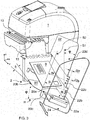
- perspektivische Darstellung eines Gutverarbeitungsgeräts mit Stapel-Box zum Stapeln von flachen Gütern.
- Die
Fig. 1a zeigt eine schematische Darstellung einer Stapel-Box von rechts, nach den Stand der Technik auf der unterschiedlich flache Güter gestapelt sind. Der Stapel ist über eine Bezugsebene an der Frontseite hinaus angewachsen und droht umzukippen oder die obersten Poststücke 3 drohen vom Stapel abzurutschen. - Die
Fig. 1b zeigt eine schematische Darstellung einer Stapel-Box von rechts, mit Stufung der Längsausrichtwand. Der Winkel α zwischen der Aufnahmeplatte und der Längsausrichtwand 22 bildet vorzugsweise einen rechten Winkel. Auf der Innenseite des Winkels verläuft eine gerade Linie, an der die Aufnahmeplatte und die Längsausrichtwand aneinander stoßen oder an der die Längsausrichtwand von der Aufnahmeplatte abgewinkelt ist. Die vorgenannte Linie an der Längsausrichtwand 22 wird nachfolgend als Längsrand bezeichnet. Die Längsausrichtwand weist vertikale Stufen auf, wobei eine parallel zu dem Längsrand verlaufende Kante 20b der Aufnahmeplatte an einer Frontseite F der Ablagevorrichtung vorgesehen ist, die sich in einem Abstand B zu dem Längsrand erstreckt, wobei sich mit jeder Stufe STi der abgestuften Längsausrichtwand ein stufenweise verringerter Abstand Bi < B der Stufe zu der Bezugsebene an der Frontseite ergibt. Der Abstand B ist die wirksame Breite der Aufnahmefläche der Aufnahmeplatte für einen Stapel. Die Aufnahmeplatte ist um den Winkel ϕ zur Horizontalen H geneigt und die Längsausrichtwand ist um den Winkel ϕ zu einer ersten Senkrechten S1 geneigt. Zu jeder Stufe STi ist ein Teilstapel Pi - mit Pi ist ein Element von P1, P2, P3, P4 - dargestellt, wobei die Teilstapel die Stufung abbilden. Für i = 1 ergibt sich eine erste Stufe ST1 und ein Teilstapel P1, der an einem ersten Teilabschnitt 22b der Längsausrichtwand 22 anliegt, der am Längsrand beginnend sich in die Höhe bis zur ersten Stufe ST1 erstreckt. Anschließend folgt ein zweiter Teilabschnitt 22c der Längsausrichtwand 22, der sich bis zur zweiten Stufe ST2 erstreckt. Ab einer dritten Stufe ST3 folgt ein dritter Teilabschnitt 22d der Längsausrichtwand 22. Am oberen Ende der Längsausrichtwand kann ein Kunststoffteil 22g befestigt sein, dass eine vierte Stufe ST4 und oberen Teilabschnitt der Längsausrichtwand 22 bildet. - Die
Fig. 2a zeigt eine schematische Darstellung einer erfindungsgemäßen Stapel-Box von rechts, mit Stufung der Längsausrichtwand 22 nach einer ersten Ausführungsvariante. Die erste Stufe ST1 ist von dem Längsrand mit der Stufenhöhe h beabstandet. Sie liegt zu dem Längsrand näher als die zweite Stufe (nicht dargestellt), die mit 2h beabstandet ist. Für jede Stufe ist vorzugsweise eine gleiche Stufenhöhe h und Stufentiefe T vorgesehen. Der Abstand B wird mit jeder Stufe i um eine Stufentiefe T verringert. Es gilt:

- Die Stufentiefe T ergibt aus einer Neigung der Aufnahmeplatte 20 in Richtung zum Längsrand der Längsausrichtwand 22 hin, bei Neigung der Aufnahmeplatte im Winkel ϕ zu einer Horizontalen H. Die maximale Stapelhöhe c des ersten Teilstapels bis zur ersten Stufe ist:

- Die Anzahl der Stufen i (mit i = 1, 2, 3, ... , n, ..., u) beträgt mindestens i = 2, vorzugsweise n und maximal i = u. Das kleinste Briefformat ist in Deutschland C6 (11.4 x 16.2 cm). Die Stufentiefe liegt deshalb vorzugsweise im Bereich T = 1 bis 7,5 cm und beispielsweise bei T = 1,44 cm. Die Stufenhöhe liegt vorzugsweise im Bereich h = 2T bis 5T und beispielsweise bei h = 4T = 6 cm. Wegen tanϕ = T / h = 1,44 / 6 = 0,24 ergibt sich ein Winkel ϕ von 15°. Beispielsweise bei T = 2,3 cm und h = 6 cm ergibt sich ein Winkel ϕ von 23,3°.
- Die Längsausrichtwand wird vertikal gestuft ausgebildet, so dass auf der Seite liegende gestapelte flache Güter ab einer bestimmten Stapelhöhe wieder eine gut erreichbare Anschlagsfläche an der Stufenunterseite vorfinden. Eine Senkrechte (gestrichelt) auf der Anschlagsfläche an der Stufenunterseite liegt vorzugsweise parallel zu einer zweiten Senkrechten S2 (gestrichelt), die auf der Aufnahmeplatte senkrecht steht. Das oberste der flachen Güter des ersten Stapels hat einen leichten Formschluß mit der Stufenunterseite, wodurch der erste Stapel einen zusätzlichen Halt bekommt. Die Stufentiefe T und/oder Stufenhöhe h kann für jede Stufe einheitlich sein oder - in einer nicht gezeigten Weise - mit der Stufenzahl abnehmen.
- Die
Fig. 2b zeigt eine schematische Darstellung einer erfindungsgemäßen Stapel-Box von rechts, mit Stufung der Längsausrichtwand mit einer alternativen Gestaltung. Eine Senkrechte auf der Anschlagsfläche liegt parallel zu einer ersten Senkrechten S1, die auf der Horizontalen H senkrecht steht. Dadurch verbessert sich der Formschluß des jeweils obersten flachen Stapelguts des Teilstapels mit der Anschlagsfläche, wenn ein weiterer Teilstapel aufliegt. Die Stapelhöhe c' bis zur ersten Stufe bleibt gleich der Stapelhöhe c, nur die Stufenhöhe h ist um Δh = T • tanϕ auf h' erhöht, wodurch der Materialverbrauch für die Längsausrichtwand ansteigt. Zwischen dem Wandteilstück das die Stufentiefe T' bestimmt und dem Wandteilstück das um Δh die Stufenhöhe h' erhöht, ist ein spitzer Winkel ausgebildet. - Dieses Detail geht aus der
Fig. 2c hervor. Die Stufentiefe T' ist zwar gegenüber T ebenfalls erhöht, aber nur marginal um ΔT' (nicht gezeigt). Der Materialmehrverbrauch dafür ist vernachlässigbar. - In einer weiteren - nicht gezeigten - Ausführungsvariante, bilden die Wandteilstücke für die Stufentiefe und die Stufenhöhe einen stumpfen Winkel. Das hat den Vorteil, dass sich das Einordnen des jeweils obersten flachen Stapelguts in den Teilstapel verbessert.
- In jeder Stufe können sich die flachen auf der Seite liegenden flachen Güter mit ihrer einen Kante wieder geordnet an der Längsausrichtwand ausrichten. Durch diese Stufen ist gewährleitet, dass die flachen Güter jedes Stapels stabiler anliegen und das jeder Stapel eine Stapelhöhe hat, die einheitlich in einem vorbestimmten Bereich liegt. Ein Kippen eines ersten Stapels nach vorne wird auch dann verhindert, obwohl ein weiterer Stapel der nächstfolgenden Stufe auf der Oberfläche des ersten Stapels nach vorn versetzt aufliegt, da das oberste der flachen Güter des ersten Stapels einen leichten Formschluss mit der Stufenunterseite hat, wodurch der erste Stapel einen zusätzlichen Halt bekommt.
- Durch Stufung ergibt sich der Vorteil einer besseren Entnahme von Teilstapeln, weil sich die Stufung in den Teilstapeln des Gesamtstapels abbildet und so die Teilstapel mehrheitlich eine annähernd gleiche Stapelhöhe aufweisen. Es muss nicht der Gesamtstapel auf einmal entnommen werden, sondern die Entnahme kann teilstapelweise von oben nach unten erfolgen.
- Alternativ können die Stufenhöhe und Stufentiefe variabel ausgeführt sein, ohne dass die die grundsätzliche Funktion der Stufung verschlechtert wird. Die Längsausrichtwand wird beispielsweise aus Metall, vorzugsweise Stahlblech hergestellt.
- Ein zusätzlicher Vorteil ergibt sich durch die Möglichkeit die Wandstärke der Längsausrichtwand weiter zu reduzieren, da die Stabilität der Längsausrichtwand durch die Stufung verbessert wird. Auch wird dadurch das Gewicht der Stapel-Box reduziert, was kundenfreundlich und kostengünstig ist.
- Die
Fig. 2d zeigt eine schematische Darstellung einer Stapel-Box von rechts und mit einem stumpfen Winkel zwischen der Aufnahmeplatte 20" und der Längsausrichtwand 22" sowie mit Stufung der Längsausrichtwand. Alternativ zu dem rechten Winkel kann ein stumpfer Winkel α realisiert werden, um die Stufentiefe zu vergrößern. Es wird folglich bei einem stumpfen Winkel α der leichte Formschluss mit der Stufenunterseite entsprechend der Erhöhung der Stufentiefe ebenfalls verbessert. - Der Abstand der Längsausrichtwand zur Bezugsebene erhöht sich bei einem stumpfen Winkel α = 90° + γ bis zur ersten Stufe um E". Der Abstand Bi" der Stufe zur Bezugsebene gegenüber dem Abstand B" den eine Kante 20b" der Aufnahmeplatte 20 an einer Frontseite F der Ablagevorrichtung zu dem Längsrand hat, verringert sich für kleinere Winkel γ < ϕ bei einer Erhöhung der Stufentiefe auf:

- Der Abstand B zu dem Längsrand wird mit jeder Stufe um einen Teil D" der Stufentiefe T" = D" + E" verringert. Es gilt:

- Die
Figur 3 zeigt eine perspektivische Darstellung einer Ablagevorrichtung, die an eine Gutverarbeitungsvorrichtung anschließt, welche einen Austrittsschlitz 13 für flache Güter aufweist und die - in einer nicht gezeigten Weise - mit einer Befestungsvorrichtung an einer Tischplatte befestigt werden kann, wobei die Ablagevorrichtung umfasst: - eine Aufnahmeplatte 20 zum Aufnehmen von flachen Gütern 3, die über den Austrittsschlitz 13 Stück für Stück ausgeworfen werden, wobei sich der Austrittsschlitz 13 am Ende eines horizontalen Decks 12 der Gutverarbeitungsvorrichtung parallel zu einer Horizontalen H erstreckt, wobei ab dem Deck 12 stromabwärts in Richtung der Flugbahn der ausgeworfenen flachen Güter die Aufnahmeplatte 20 einerseits nach unten in einem Winkel β bezogen auf die Transportrichtung z der flachen Güter auf dem Deck und andererseits nach hinten in Richtung x zu der abgestuften Längsausrichtwand 22 in einem Winkel ϕ bezogen auf die Horizontale H geneigt ist;
- eine in mindestens zwei Stufen n abgestufte Längsausrichtwand 22 an einer Rückseite der Ablagevorrichtung 2 angeordnet ist, wobei sich die Längsausrichtwand 22 einerseits mit einen Längsrand 22a stromabwärts erstreckt und andererseits in einem Winkel ϕ zu einer ersten Senkrechten S1 auf der Horizontalen H geneigt ist, wobei der Längsrand 22a in einem Abstand B parallel zu einer Kante 20b der Aufnahmeplatte 20 an einer Frontseite F der Ablagevorrichtung verläuft, wobei die erste Senkrechten S1 zu dem horizontalen Deck 12 senkrecht steht und wobei eine erste Anschlagsfläche 22b senkrecht im Winkel α = 90° oder im Winkel α größer als 90° zur Aufnahmeplatte 20 angeordnet ist und
- eine Stopwand 24, die sich entlang eines Seitenrandes 20c der Aufnahmeplatte 20 erstreckt.
- Es ist vorgesehen, dass die Stopwand 24 am stromabwärtigen Ende der Aufnahmeplatte angeordnet sowie in Längsrichtung (weißer Pfeil) verschiebbar ausgebildet ist. Entweder verläuft die Stopwand 24 parallel zu einer Senkrechten auf der Längsausrichtwand 22 und erstreckt sich parallel zu der zweiten Senkrechten S2 auf der Aufnahmeplatte 20 nach oben oder die Stopwand 24 ist senkrecht zum Deck 12 ausgerichtet und erstreckt sich parallel zu der ersten Senkrechten S1 in y-Richtung.
- Es ist ebenfalls vorgesehen, dass die Ablagevorrichtung 2 stromabwärts an eine Gutverarbeitungsvorrichtung angeordnet ist, dass ein Teleskop-Bein zur zusätzlichen Stützung der Aufnahmeplatte 20 nahe dem stromabwärtigen Ende der Ablagevorrichtung angeordnet ist, dass das Teleskop-Bein einen ausziehbaren Fuß und einen Kopf aufweist, der mit der Aufnahmeplatte lösbar verbunden ist, dass der Kopf am stromabwärtigen Ende der Aufnahmeplatte Öffnungen für einen schienenartigen Träger aufweist, an welchem die Stopwand 24 montiert ist und dass der schienenartigen Träger in Längsrichtung verschiebbar ausgebildet ist, sowie dass eine Befestungsvorrichtung vorgesehen ist, mit welcher die Ablagevorrichtung mit ihrem anderen Ende an einer Tischplatte befestigt werden kann. Die Befestungsvorrichtung weist - in an sich bekannter Weise - Klammern oder Schraubzwingen oder vergleichbare Befestigungsmittel auf.
- Es ist weiter vorgesehen, dass die Stufentiefe T und/oder die Stufenhöhe h für jede Stufe einheitlich oder mit der Stufenzahl abnehmend ausgebildet ist. Alternativ können auch einzelne Stufen von den einheitlichen Größen der Dimensionen abweisen.
- Die perspektivische Darstellung einer Ablagevorrichtung nach
Fig. 3 zeigt ab der zweiten Stufe eine mehr als doppelte Höhe des dritten Teilabschnitts 22d der Längsausrichtwand 22. Am oberen Ende der Längsausrichtwand kann - in einer nicht gezeigten Weise - ein Kunststoffteil befestigt werden, dass in den Innenraum der Ablagevorrichtung hineinragt, um eine vierte Stufe zu bilden. - Der Winkel α zwischen der Aufnahmeplatte 20 und der Längsausrichtwand 22 ist in der Darstellung nach
Fig. 3 ein rechter Winkel α. - Für die Winkel sind folgende Winkelbereiche vorgesehen:
- α = 90° - 120°,
- β = 2°- 45° und
- ϕ = 2°- 45°.
- Die Ablagevorrichtung 2 ist beispielsweise für den Betrieb an einer Frankiermaschine 1 speziell zur Ablage von Mischpost vorgesehen. Die Aufnahmeplatte 20 besteht aus einer Metallblechplatte, die eine Kante 20c an der Stopseite aufweist, wobei die Metallblechplatte an der Kante 20c nach unten abgewinkelt ist. In der Abwinkelung sind Öffnungen für einen schienenartigen und ausziehbaren Träger angeordnet, an welchem die Stopwand 24 montiert ist. Bevorzugt werden die Aufnahmeplatte 20 und die Längsausrichtwand 22 aus zwei Metallblechplatten hergestellt. Die Aufnahmeplatte 20 geht dann über die für eine Ablage wirksame Breite B hinaus bis zu einer Abwicklungskante (nicht gezeigt), die einen Abstand zu der Linie 20a hat. Die Linie 20a hat ihrerseits von der Kante 20b den Abstand B. An die Linie 20a stößt ein Längsrand 22a der Längsausrichtwand 22 bei einer Montage auf die Aufnahmeplatte 20.
- Alternativ hat die Aufnahmeplatte 20 auch eine wirksame Breite B von der Kante 20b an der Frontseite bis zum Längsrand 20a, wenn die Metallblechplatte am Längsrand 20a nach oben abgewinkelt ist und in eine Längsausrichtwand 22 übergeht.
- Die Längsausrichtwand 22 hat in der bevorzugten Ausführungsvariante einen folgenden Aufbau bzw. Dimensionen: Metallblech mit 1 cm Dicke. Bei 275 cm Länge des Längsrandes 22a verläuft die stromabwärtige Kante in einem spitzen Winkel von beispielsweise 74,9° zum Längsrand 22a der Längsausrichtwand 22.
- Die Stufen verlaufen parallel zum Längsrand 20a. Die Stufenhöhe des ersten Teilabschnitts 22d der Längsausrichtwand 22 beträgt h = 6,1 cm. Die Stufenhöhe des zweiten Teilabschnitts 22c der Längsausrichtwand 22 beträgt h = 6,0 cm. Die Stufenhöhe des dritten Teilabschnitts 22d der Längsausrichtwand 22 beträgt h = 5,9 cm, bei einem auf der Längsausrichtwand 22 montierten Kunststoffteil 22g, dessen stromabwärtige Kante 13,7 cm lang ist. Parallel zu der stromabwärtigen Kante verläuft die stromaufwärtige Kante des montierten Kunststoffteils 22g, deren Länge L ca. 13,7 cm ist. Die stromaufwärtige Kante des Metallblechs ist insgesamt 24,5 cm und die stromabwärtige Kante des Metallblechs ist insgesamt 330 cm lang. Die obere Kante ist an den Ecken abgerundet und insgesamt nur 26,1 cm lang und verläuft parallel der Transportrichtung z des Poststücks 3 auf dem Deck 12.
- Die Stopwand 24 besteht aus einem durchsichtigen Kunststoff, beispielsweise aus Acrylglas, mit 6 cm Dicke und 164 cm Breite. Die Höhe der Stopwand an der Frontseite der Ablagevorrichtung beträgt mindestens 22,5 und die Höhe an der Rückseite beträgt maximal 33 cm. Die Ecken der Stopwand 24 sind abgerundet.
- Wenn im vorliegenden Beispiel eine bestimmte Ausführungsform, nämlich bevorzugt eine Stufung nach einer ersten Variante näher erläutert wurde, soll aber dadurch nicht eine andere Ausführungsform nach einer weiteren Variante vom Schutzumfang ausgeschlossen werden, die - vom gleichen Grundgedanken der Erfindung ausgehend - eingesetzt werden kann und von den anliegenden Patentansprüchen umfasst wird.
Claims (8)
- Ablagevorrichtung, umfassend eine Aufnahmeplatte zum Aufnehmen von flachen Gütern, eine in mindestens zwei Stufen abgestufte Längsausrichtwand an einer Rückseite der Ablagevorrichtung und eine Stopwand, die am stromabwärtigen Ende der Aufnahmeplatte angeordnet ist.
- Ablagevorrichtung, nach Anspruch 1, gekennzeichnet dadurch, dass- eine Aufnahmeplatte (20) zum Aufnehmen von flachen Gütern (3) vorgesehen ist, die Stück für Stück über einen Austrittsschlitz (13) ausgeworfen werden, wobei sich der Austrittsschlitz (13) am Ende eines horizontalen Decks (12) einer Gutverarbeitungsvorrichtung parallel zu einer Horizontalen H erstreckt, wobei die Aufnahmeplatte (20) einerseits ab dem Deck (12) stromabwärts in Richtung der Flugbahn der ausgeworfenen flachen Güter (3) nach unten in einem Winkel β bezogen auf die Transportrichtung z der flachen Güter auf dem Deck und andererseits nach hinten in Richtung x zu der abgestuften Längsausrichtwand (22) in einem Winkel ϕ bezogen auf die Horizontale H geneigt ist;- die in mindestens zwei Stufen n abgestufte Längsausrichtwand (22) an einer Rückseite der Ablagevorrichtung (2) angeordnet ist, wobei sich die Längsausrichtwand (22) einerseits stromabwärts mit einen Längsrand (22a) erstreckt und andererseits in einem Winkel ϕ zu einer ersten Senkrechten S1 auf der Horizontalen H geneigt ist, wobei der Längsrand (22a) in einem Abstand B parallel zu einer Kante (20b) der Aufnahmeplatte (20) an einer Frontseite F der Ablagevorrichtung verläuft, wobei die erste Senkrechten S1 zu dem horizontalen Deck (12) senkrecht steht und wobei eine erste Anschlagsfläche (22b) senkrecht im Winkel α = 90° oder im Winkel α größer als 90° zur Aufnahmeplatte (20) angeordnet ist und- eine Stopwand (24) am stromabwärtigen Ende der Ablagevorrichtung vorgesehen ist und sich entlang eines Seitenrandes (20c) der Aufnahmeplatte (20) erstreckt.
- Ablagevorrichtung, nach den Ansprüchen 1 und 2, gekennzeichnet dadurch, dass der Winkel α zwischen der Aufnahmeplatte (20) und der Längsausrichtwand (22) in einem Winkelbereich 90° ≤ α ≤ 120° liegt und dass die Stopwand (24) am stromabwärtigen Ende der Aufnahmeplatte angeordnet sowie in Längsrichtung verschiebbar ausgebildet ist.
- Ablagevorrichtung, nach den Ansprüchen 1 bis 3, gekennzeichnet dadurch, dass die Stufentiefe T und/oder Stufenhöhe h für jede Stufe einheitlich oder mit der Stufenzahl abnehmend ausgebildet ist.
- Ablagevorrichtung, nach den Ansprüchen 1 bis 4, gekennzeichnet dadurch, dass sich die Stopwand (24) parallel zu einer Senkrechten auf der Längsausrichtwand (22) und sich parallel zu der zweiten Senkrechten S2 auf der Aufnahmeplatte (20) nach oben erstreckt.
- Ablagevorrichtung, nach den Ansprüchen 1 bis 4, gekennzeichnet dadurch, dass die Stopwand (24) senkrecht zum Deck (12) ausgerichtet ist und sich parallel zu der ersten Senkrechten S1 erstreckt.
- Ablagevorrichtung, nach den Ansprüchen 1 bis 4, gekennzeichnet dadurch, dass die Ablagevorrichtung (2) stromabwärts an die Gutverarbeitungsvorrichtung angeordnet ist, dass ein Teleskop-Bein zur zusätzlichen Stützung der Aufnahmeplatte (20) nahe dem stromabwärtigen Ende der Ablagevorrichtung angeordnet ist, dass das Teleskop-Bein einen ausziehbaren Fuß und einen Kopf aufweist, der mit der Aufnahmeplatte lösbar verbunden ist, dass der Kopf am stromabwärtigen Ende der Aufnahmeplatte Öffnungen für einen schienenartigen Träger aufweist, an welchem die Stopwand (24) montiert ist und dass der schienenartigen Träger in Längsrichtung verschiebbar ausgebildet ist, sowie dass eine Befestungsvorrichtung vorgesehen ist, mit welcher die Ablagevorrichtung mit ihrem anderen Ende an einer Tischplatte befestigt werden kann, auf der die Gutverarbeitungsvorrichtung steht.
- Ablagevorrichtung, nach einem der vorgenannten Ansprüche 1 bis 7, gekennzeichnet dadurch, dass die Gutverarbeitungsvorrichtung eine Frankiermaschine (1) ist und das die flachen Güter Poststücke sind.
Applications Claiming Priority (1)
| Application Number | Priority Date | Filing Date | Title |
|---|---|---|---|
| DE202016100099.8U DE202016100099U1 (de) | 2016-01-12 | 2016-01-12 | Ablagevorrichtung für flache Güter |
Publications (2)
| Publication Number | Publication Date |
|---|---|
| EP3192757A1 true EP3192757A1 (de) | 2017-07-19 |
| EP3192757B1 EP3192757B1 (de) | 2020-04-08 |
Family
ID=55358950
Family Applications (1)
| Application Number | Title | Priority Date | Filing Date |
|---|---|---|---|
| EP16202399.8A Active EP3192757B1 (de) | 2016-01-12 | 2016-12-06 | Ablagevorrichtung für flache güter |
Country Status (5)
| Country | Link |
|---|---|
| US (1) | US10011452B2 (de) |
| EP (1) | EP3192757B1 (de) |
| CA (1) | CA2954160C (de) |
| DE (1) | DE202016100099U1 (de) |
| NO (1) | NO349494B1 (de) |
Families Citing this family (1)
| Publication number | Priority date | Publication date | Assignee | Title |
|---|---|---|---|---|
| CN108357968B (zh) * | 2018-04-17 | 2024-07-02 | 茉织华印务股份有限公司 | 一种印刷设备的纸张收集机构 |
Citations (9)
| Publication number | Priority date | Publication date | Assignee | Title |
|---|---|---|---|---|
| JP2000063026A (ja) | 1998-08-24 | 2000-02-29 | Tohoku Ricoh Co Ltd | 小サイズ印刷物排紙ボックス |
| JP2002234659A (ja) | 2001-02-08 | 2002-08-23 | Musashi:Kk | 紙受け装置 |
| US6648284B2 (en) | 2001-09-05 | 2003-11-18 | Lockheed Martin Corporation | Flat tub mail positional orientation justification insert |
| EP0985619B1 (de) | 1998-09-08 | 2004-02-18 | Francotyp-Postalia AG & Co. KG | Vorrichtung zur Übergabe von Postgut an eine Ablagevorrichtung |
| US20070090590A1 (en) * | 2005-10-20 | 2007-04-26 | Pitney Bowes Incorporated | Vertical mail piece stacker |
| EP1443008B1 (de) | 2003-01-30 | 2008-11-26 | Neopost Technologies | Vorrichtung zum Aufnehmen von Briefumschlägen |
| US7568694B2 (en) | 2006-11-27 | 2009-08-04 | Eastman Kodak Company | Printed medium collector |
| US20110074084A1 (en) * | 2009-09-28 | 2011-03-31 | Hon Hai Precision Industry Co., Ltd. | Printer |
| EP2361864A1 (de) * | 2010-02-23 | 2011-08-31 | Neopost Technologies | Vorrichtung zur Lagerung von Postartikeln |
Family Cites Families (10)
| Publication number | Priority date | Publication date | Assignee | Title |
|---|---|---|---|---|
| FR2349897A1 (fr) * | 1976-04-29 | 1977-11-25 | Honeywell Bull Soc Ind | Case de reception de documents |
| US5188353A (en) * | 1990-08-17 | 1993-02-23 | Xerox Corporation | Disk stacker including tamping mechanism capable of cross-direction offsetting |
| US5332210A (en) | 1992-11-18 | 1994-07-26 | Pitney Bowes Inc. | Variable size envelope drop stacker having means for assuring envelope sealing |
| JP3267382B2 (ja) * | 1993-05-17 | 2002-03-18 | 理想科学工業株式会社 | 薄葉体積載受容装置 |
| DE60324846D1 (de) * | 2003-04-30 | 2009-01-02 | Hewlett Packard Development Co | Schliessblech und dessen verwendung in einer bogenausgabestation |
| US7766171B2 (en) | 2008-02-28 | 2010-08-03 | Northrop Grumman Systems Corporation | Rigid storage tray for flat and letter mail |
| JP5212136B2 (ja) | 2009-01-23 | 2013-06-19 | セイコーエプソン株式会社 | 画像記録装置 |
| JP5560969B2 (ja) * | 2010-07-05 | 2014-07-30 | 沖電気工業株式会社 | 紙葉類集積装置 |
| JP5871510B2 (ja) * | 2011-08-08 | 2016-03-01 | キヤノン株式会社 | シート給送装置及び画像形成装置 |
| US9260262B2 (en) | 2014-01-17 | 2016-02-16 | Canon Kabushiki Kaisha | Sheet stacking apparatus, sheet feeding apparatus and image forming apparatus |
-
2016
- 2016-01-12 DE DE202016100099.8U patent/DE202016100099U1/de not_active Expired - Lifetime
- 2016-12-06 EP EP16202399.8A patent/EP3192757B1/de active Active
- 2016-12-12 US US15/375,328 patent/US10011452B2/en active Active
-
2017
- 2017-01-09 NO NO20170033A patent/NO349494B1/en unknown
- 2017-01-10 CA CA2954160A patent/CA2954160C/en active Active
Patent Citations (10)
| Publication number | Priority date | Publication date | Assignee | Title |
|---|---|---|---|---|
| JP2000063026A (ja) | 1998-08-24 | 2000-02-29 | Tohoku Ricoh Co Ltd | 小サイズ印刷物排紙ボックス |
| EP0985619B1 (de) | 1998-09-08 | 2004-02-18 | Francotyp-Postalia AG & Co. KG | Vorrichtung zur Übergabe von Postgut an eine Ablagevorrichtung |
| JP2002234659A (ja) | 2001-02-08 | 2002-08-23 | Musashi:Kk | 紙受け装置 |
| US6648284B2 (en) | 2001-09-05 | 2003-11-18 | Lockheed Martin Corporation | Flat tub mail positional orientation justification insert |
| EP1443008B1 (de) | 2003-01-30 | 2008-11-26 | Neopost Technologies | Vorrichtung zum Aufnehmen von Briefumschlägen |
| US20070090590A1 (en) * | 2005-10-20 | 2007-04-26 | Pitney Bowes Incorporated | Vertical mail piece stacker |
| US7568694B2 (en) | 2006-11-27 | 2009-08-04 | Eastman Kodak Company | Printed medium collector |
| US20110074084A1 (en) * | 2009-09-28 | 2011-03-31 | Hon Hai Precision Industry Co., Ltd. | Printer |
| EP2361864A1 (de) * | 2010-02-23 | 2011-08-31 | Neopost Technologies | Vorrichtung zur Lagerung von Postartikeln |
| US8590888B2 (en) | 2010-02-23 | 2013-11-26 | Neopost Technologies | Device for storing mailpieces |
Also Published As
| Publication number | Publication date |
|---|---|
| CA2954160C (en) | 2019-02-12 |
| CA2954160A1 (en) | 2017-07-12 |
| NO20170033A1 (en) | 2017-07-13 |
| NO349494B1 (en) | 2026-02-02 |
| DE202016100099U1 (de) | 2016-02-01 |
| EP3192757B1 (de) | 2020-04-08 |
| US10011452B2 (en) | 2018-07-03 |
| US20170197800A1 (en) | 2017-07-13 |
Similar Documents
| Publication | Publication Date | Title |
|---|---|---|
| DE68924859T2 (de) | Zuführvorrichtung von gestapelten Werkstücken. | |
| DE69407236T2 (de) | System zum Stapeln von Blättern mit grossem Aufnahmevermögen und mit einer in der Höhe variierbaren Eingabe und Stapelausrichtung | |
| DE2816448A1 (de) | Vorrichtung zum zufuehren von papierblaettern fuer eine schreibende bueromaschine | |
| DE3873075T2 (de) | Vorrichtung zum automatischen ausgeben von gegenstaenden. | |
| DE602005006336T2 (de) | Bogentrennglied und -zuführvorrichtung | |
| EP3315438A1 (de) | Vereinzelungsstation für flaches gut und zu dessen zuführung zu einer gutverarbeitungsstation | |
| EP2355938B1 (de) | Postsortieranlage mit mehreren ausgabeeinrichtungen und postsortierverfahren | |
| EP1456106A1 (de) | Verfahren und vorrichtung zur bildung von gruppen von flachen gegenständen | |
| EP3192757B1 (de) | Ablagevorrichtung für flache güter | |
| DE19718998C2 (de) | Vorrichtung zum Zusammentragen von Papieren | |
| EP2586737B1 (de) | Modulare Anlegevorrichtung einer Zuführstation | |
| DE69702297T2 (de) | Überfüllschutzvorrichtung für ein Aufzeichnungsträgereingabefach | |
| DE10345770B3 (de) | Aufgabestation zum Auflegen von Beilagen auf eine Beilagen-Zusammentragbahn | |
| DE3443735C2 (de) | ||
| EP0985619B1 (de) | Vorrichtung zur Übergabe von Postgut an eine Ablagevorrichtung | |
| DE19900687B4 (de) | Anordnung zur Ablage von Aufzeichnungsträgern | |
| EP2067535A1 (de) | Verfahren zum Sortieren von flachen Postsendungen | |
| EP2815994B1 (de) | Anleger für flache Güter, insbesondere Beilagenanleger, und Verfahren zum Abziehen flacher Güter aus einem Stapel | |
| DE69307100T2 (de) | Zwischenspeicher/Stapelvorrichtung | |
| DE10024720B4 (de) | Verbessern der Stapelqualität von gedrucktem Papier | |
| DE3941477A1 (de) | Vorrichtung zum ablegen von kopieblaettern | |
| DE69710805T2 (de) | Ausgabevorrichtung für eine Druckeinrichtung | |
| DE69110121T2 (de) | Zuführungs- und Abgabestruktur für Einzelblätter in einem Drucker. | |
| EP2034452A1 (de) | Verfahren zum Frankieren, Bedrucken und Bebildern von flachen Versandobjekten | |
| DE102006044137B3 (de) | System und Verfahren zur Sortierung von flachen Poststücken mit Lückensteuerung zur Durchsatzerhöhung |
Legal Events
| Date | Code | Title | Description |
|---|---|---|---|
| PUAI | Public reference made under article 153(3) epc to a published international application that has entered the european phase |
Free format text: ORIGINAL CODE: 0009012 |
|
| STAA | Information on the status of an ep patent application or granted ep patent |
Free format text: STATUS: THE APPLICATION HAS BEEN PUBLISHED |
|
| AK | Designated contracting states |
Kind code of ref document: A1 Designated state(s): AL AT BE BG CH CY CZ DE DK EE ES FI FR GB GR HR HU IE IS IT LI LT LU LV MC MK MT NL NO PL PT RO RS SE SI SK SM TR |
|
| AX | Request for extension of the european patent |
Extension state: BA ME |
|
| STAA | Information on the status of an ep patent application or granted ep patent |
Free format text: STATUS: REQUEST FOR EXAMINATION WAS MADE |
|
| 17P | Request for examination filed |
Effective date: 20171212 |
|
| RBV | Designated contracting states (corrected) |
Designated state(s): AL AT BE BG CH CY CZ DE DK EE ES FI FR GB GR HR HU IE IS IT LI LT LU LV MC MK MT NL NO PL PT RO RS SE SI SK SM TR |
|
| GRAP | Despatch of communication of intention to grant a patent |
Free format text: ORIGINAL CODE: EPIDOSNIGR1 |
|
| STAA | Information on the status of an ep patent application or granted ep patent |
Free format text: STATUS: GRANT OF PATENT IS INTENDED |
|
| INTG | Intention to grant announced |
Effective date: 20191220 |
|
| GRAS | Grant fee paid |
Free format text: ORIGINAL CODE: EPIDOSNIGR3 |
|
| GRAA | (expected) grant |
Free format text: ORIGINAL CODE: 0009210 |
|
| STAA | Information on the status of an ep patent application or granted ep patent |
Free format text: STATUS: THE PATENT HAS BEEN GRANTED |
|
| AK | Designated contracting states |
Kind code of ref document: B1 Designated state(s): AL AT BE BG CH CY CZ DE DK EE ES FI FR GB GR HR HU IE IS IT LI LT LU LV MC MK MT NL NO PL PT RO RS SE SI SK SM TR |
|
| REG | Reference to a national code |
Ref country code: AT Ref legal event code: REF Ref document number: 1254116 Country of ref document: AT Kind code of ref document: T Effective date: 20200415 Ref country code: CH Ref legal event code: EP |
|
| REG | Reference to a national code |
Ref country code: DE Ref legal event code: R096 Ref document number: 502016009451 Country of ref document: DE |
|
| REG | Reference to a national code |
Ref country code: IE Ref legal event code: FG4D Free format text: LANGUAGE OF EP DOCUMENT: GERMAN |
|
| REG | Reference to a national code |
Ref country code: SE Ref legal event code: TRGR |
|
| REG | Reference to a national code |
Ref country code: NL Ref legal event code: FP |
|
| REG | Reference to a national code |
Ref country code: LT Ref legal event code: MG4D |
|
| PG25 | Lapsed in a contracting state [announced via postgrant information from national office to epo] |
Ref country code: GR Free format text: LAPSE BECAUSE OF FAILURE TO SUBMIT A TRANSLATION OF THE DESCRIPTION OR TO PAY THE FEE WITHIN THE PRESCRIBED TIME-LIMIT Effective date: 20200709 Ref country code: NO Free format text: LAPSE BECAUSE OF FAILURE TO SUBMIT A TRANSLATION OF THE DESCRIPTION OR TO PAY THE FEE WITHIN THE PRESCRIBED TIME-LIMIT Effective date: 20200708 Ref country code: IS Free format text: LAPSE BECAUSE OF FAILURE TO SUBMIT A TRANSLATION OF THE DESCRIPTION OR TO PAY THE FEE WITHIN THE PRESCRIBED TIME-LIMIT Effective date: 20200808 Ref country code: PT Free format text: LAPSE BECAUSE OF FAILURE TO SUBMIT A TRANSLATION OF THE DESCRIPTION OR TO PAY THE FEE WITHIN THE PRESCRIBED TIME-LIMIT Effective date: 20200817 Ref country code: LT Free format text: LAPSE BECAUSE OF FAILURE TO SUBMIT A TRANSLATION OF THE DESCRIPTION OR TO PAY THE FEE WITHIN THE PRESCRIBED TIME-LIMIT Effective date: 20200408 Ref country code: FI Free format text: LAPSE BECAUSE OF FAILURE TO SUBMIT A TRANSLATION OF THE DESCRIPTION OR TO PAY THE FEE WITHIN THE PRESCRIBED TIME-LIMIT Effective date: 20200408 |
|
| PG25 | Lapsed in a contracting state [announced via postgrant information from national office to epo] |
Ref country code: BG Free format text: LAPSE BECAUSE OF FAILURE TO SUBMIT A TRANSLATION OF THE DESCRIPTION OR TO PAY THE FEE WITHIN THE PRESCRIBED TIME-LIMIT Effective date: 20200708 Ref country code: LV Free format text: LAPSE BECAUSE OF FAILURE TO SUBMIT A TRANSLATION OF THE DESCRIPTION OR TO PAY THE FEE WITHIN THE PRESCRIBED TIME-LIMIT Effective date: 20200408 Ref country code: RS Free format text: LAPSE BECAUSE OF FAILURE TO SUBMIT A TRANSLATION OF THE DESCRIPTION OR TO PAY THE FEE WITHIN THE PRESCRIBED TIME-LIMIT Effective date: 20200408 Ref country code: HR Free format text: LAPSE BECAUSE OF FAILURE TO SUBMIT A TRANSLATION OF THE DESCRIPTION OR TO PAY THE FEE WITHIN THE PRESCRIBED TIME-LIMIT Effective date: 20200408 |
|
| PG25 | Lapsed in a contracting state [announced via postgrant information from national office to epo] |
Ref country code: AL Free format text: LAPSE BECAUSE OF FAILURE TO SUBMIT A TRANSLATION OF THE DESCRIPTION OR TO PAY THE FEE WITHIN THE PRESCRIBED TIME-LIMIT Effective date: 20200408 |
|
| REG | Reference to a national code |
Ref country code: DE Ref legal event code: R097 Ref document number: 502016009451 Country of ref document: DE |
|
| PG25 | Lapsed in a contracting state [announced via postgrant information from national office to epo] |
Ref country code: CZ Free format text: LAPSE BECAUSE OF FAILURE TO SUBMIT A TRANSLATION OF THE DESCRIPTION OR TO PAY THE FEE WITHIN THE PRESCRIBED TIME-LIMIT Effective date: 20200408 Ref country code: RO Free format text: LAPSE BECAUSE OF FAILURE TO SUBMIT A TRANSLATION OF THE DESCRIPTION OR TO PAY THE FEE WITHIN THE PRESCRIBED TIME-LIMIT Effective date: 20200408 Ref country code: DK Free format text: LAPSE BECAUSE OF FAILURE TO SUBMIT A TRANSLATION OF THE DESCRIPTION OR TO PAY THE FEE WITHIN THE PRESCRIBED TIME-LIMIT Effective date: 20200408 Ref country code: EE Free format text: LAPSE BECAUSE OF FAILURE TO SUBMIT A TRANSLATION OF THE DESCRIPTION OR TO PAY THE FEE WITHIN THE PRESCRIBED TIME-LIMIT Effective date: 20200408 Ref country code: SM Free format text: LAPSE BECAUSE OF FAILURE TO SUBMIT A TRANSLATION OF THE DESCRIPTION OR TO PAY THE FEE WITHIN THE PRESCRIBED TIME-LIMIT Effective date: 20200408 Ref country code: ES Free format text: LAPSE BECAUSE OF FAILURE TO SUBMIT A TRANSLATION OF THE DESCRIPTION OR TO PAY THE FEE WITHIN THE PRESCRIBED TIME-LIMIT Effective date: 20200408 |
|
| PLBE | No opposition filed within time limit |
Free format text: ORIGINAL CODE: 0009261 |
|
| STAA | Information on the status of an ep patent application or granted ep patent |
Free format text: STATUS: NO OPPOSITION FILED WITHIN TIME LIMIT |
|
| PG25 | Lapsed in a contracting state [announced via postgrant information from national office to epo] |
Ref country code: SK Free format text: LAPSE BECAUSE OF FAILURE TO SUBMIT A TRANSLATION OF THE DESCRIPTION OR TO PAY THE FEE WITHIN THE PRESCRIBED TIME-LIMIT Effective date: 20200408 Ref country code: PL Free format text: LAPSE BECAUSE OF FAILURE TO SUBMIT A TRANSLATION OF THE DESCRIPTION OR TO PAY THE FEE WITHIN THE PRESCRIBED TIME-LIMIT Effective date: 20200408 |
|
| 26N | No opposition filed |
Effective date: 20210112 |
|
| PG25 | Lapsed in a contracting state [announced via postgrant information from national office to epo] |
Ref country code: SI Free format text: LAPSE BECAUSE OF FAILURE TO SUBMIT A TRANSLATION OF THE DESCRIPTION OR TO PAY THE FEE WITHIN THE PRESCRIBED TIME-LIMIT Effective date: 20200408 |
|
| PG25 | Lapsed in a contracting state [announced via postgrant information from national office to epo] |
Ref country code: MC Free format text: LAPSE BECAUSE OF FAILURE TO SUBMIT A TRANSLATION OF THE DESCRIPTION OR TO PAY THE FEE WITHIN THE PRESCRIBED TIME-LIMIT Effective date: 20200408 |
|
| REG | Reference to a national code |
Ref country code: BE Ref legal event code: MM Effective date: 20201231 |
|
| PG25 | Lapsed in a contracting state [announced via postgrant information from national office to epo] |
Ref country code: LU Free format text: LAPSE BECAUSE OF NON-PAYMENT OF DUE FEES Effective date: 20201206 Ref country code: IE Free format text: LAPSE BECAUSE OF NON-PAYMENT OF DUE FEES Effective date: 20201206 |
|
| PG25 | Lapsed in a contracting state [announced via postgrant information from national office to epo] |
Ref country code: TR Free format text: LAPSE BECAUSE OF FAILURE TO SUBMIT A TRANSLATION OF THE DESCRIPTION OR TO PAY THE FEE WITHIN THE PRESCRIBED TIME-LIMIT Effective date: 20200408 Ref country code: MT Free format text: LAPSE BECAUSE OF FAILURE TO SUBMIT A TRANSLATION OF THE DESCRIPTION OR TO PAY THE FEE WITHIN THE PRESCRIBED TIME-LIMIT Effective date: 20200408 Ref country code: CY Free format text: LAPSE BECAUSE OF FAILURE TO SUBMIT A TRANSLATION OF THE DESCRIPTION OR TO PAY THE FEE WITHIN THE PRESCRIBED TIME-LIMIT Effective date: 20200408 |
|
| PG25 | Lapsed in a contracting state [announced via postgrant information from national office to epo] |
Ref country code: MK Free format text: LAPSE BECAUSE OF FAILURE TO SUBMIT A TRANSLATION OF THE DESCRIPTION OR TO PAY THE FEE WITHIN THE PRESCRIBED TIME-LIMIT Effective date: 20200408 |
|
| PG25 | Lapsed in a contracting state [announced via postgrant information from national office to epo] |
Ref country code: BE Free format text: LAPSE BECAUSE OF NON-PAYMENT OF DUE FEES Effective date: 20201231 |
|
| P01 | Opt-out of the competence of the unified patent court (upc) registered |
Effective date: 20230807 |
|
| REG | Reference to a national code |
Ref country code: CH Ref legal event code: U11 Free format text: ST27 STATUS EVENT CODE: U-0-0-U10-U11 (AS PROVIDED BY THE NATIONAL OFFICE) Effective date: 20260101 |
|
| PGFP | Annual fee paid to national office [announced via postgrant information from national office to epo] |
Ref country code: DE Payment date: 20251017 Year of fee payment: 10 |
|
| PGFP | Annual fee paid to national office [announced via postgrant information from national office to epo] |
Ref country code: GB Payment date: 20251219 Year of fee payment: 10 |
|
| PGFP | Annual fee paid to national office [announced via postgrant information from national office to epo] |
Ref country code: AT Payment date: 20251222 Year of fee payment: 10 |
|
| PGFP | Annual fee paid to national office [announced via postgrant information from national office to epo] |
Ref country code: IT Payment date: 20251223 Year of fee payment: 10 |
|
| PGFP | Annual fee paid to national office [announced via postgrant information from national office to epo] |
Ref country code: NL Payment date: 20251219 Year of fee payment: 10 Ref country code: FR Payment date: 20251223 Year of fee payment: 10 |
|
| PGFP | Annual fee paid to national office [announced via postgrant information from national office to epo] |
Ref country code: SE Payment date: 20251219 Year of fee payment: 10 |
|
| PGFP | Annual fee paid to national office [announced via postgrant information from national office to epo] |
Ref country code: CH Payment date: 20260101 Year of fee payment: 10 |