EP3189757B1 - Shower head with which shower sensations can be obtained without providing water sprinkling plate - Google Patents
Shower head with which shower sensations can be obtained without providing water sprinkling plate Download PDFInfo
- Publication number
- EP3189757B1 EP3189757B1 EP15809544.8A EP15809544A EP3189757B1 EP 3189757 B1 EP3189757 B1 EP 3189757B1 EP 15809544 A EP15809544 A EP 15809544A EP 3189757 B1 EP3189757 B1 EP 3189757B1
- Authority
- EP
- European Patent Office
- Prior art keywords
- shower
- plate
- micro bubble
- bubble generator
- ridge
- Prior art date
- Legal status (The legal status is an assumption and is not a legal conclusion. Google has not performed a legal analysis and makes no representation as to the accuracy of the status listed.)
- Active
Links
Images


Classifications
-
- B—PERFORMING OPERATIONS; TRANSPORTING
- B05—SPRAYING OR ATOMISING IN GENERAL; APPLYING FLUENT MATERIALS TO SURFACES, IN GENERAL
- B05B—SPRAYING APPARATUS; ATOMISING APPARATUS; NOZZLES
- B05B15/00—Details of spraying plant or spraying apparatus not otherwise provided for; Accessories
- B05B15/60—Arrangements for mounting, supporting or holding spraying apparatus
- B05B15/62—Arrangements for supporting spraying apparatus, e.g. suction cups
-
- B—PERFORMING OPERATIONS; TRANSPORTING
- B05—SPRAYING OR ATOMISING IN GENERAL; APPLYING FLUENT MATERIALS TO SURFACES, IN GENERAL
- B05B—SPRAYING APPARATUS; ATOMISING APPARATUS; NOZZLES
- B05B1/00—Nozzles, spray heads or other outlets, with or without auxiliary devices such as valves, heating means
- B05B1/02—Nozzles, spray heads or other outlets, with or without auxiliary devices such as valves, heating means designed to produce a jet, spray, or other discharge of particular shape or nature, e.g. in single drops, or having an outlet of particular shape
-
- B—PERFORMING OPERATIONS; TRANSPORTING
- B05—SPRAYING OR ATOMISING IN GENERAL; APPLYING FLUENT MATERIALS TO SURFACES, IN GENERAL
- B05B—SPRAYING APPARATUS; ATOMISING APPARATUS; NOZZLES
- B05B1/00—Nozzles, spray heads or other outlets, with or without auxiliary devices such as valves, heating means
- B05B1/14—Nozzles, spray heads or other outlets, with or without auxiliary devices such as valves, heating means with multiple outlet openings; with strainers in or outside the outlet opening
- B05B1/18—Roses; Shower heads
-
- B—PERFORMING OPERATIONS; TRANSPORTING
- B05—SPRAYING OR ATOMISING IN GENERAL; APPLYING FLUENT MATERIALS TO SURFACES, IN GENERAL
- B05B—SPRAYING APPARATUS; ATOMISING APPARATUS; NOZZLES
- B05B1/00—Nozzles, spray heads or other outlets, with or without auxiliary devices such as valves, heating means
- B05B1/34—Nozzles, spray heads or other outlets, with or without auxiliary devices such as valves, heating means designed to influence the nature of flow of the liquid or other fluent material, e.g. to produce swirl
- B05B1/3405—Nozzles, spray heads or other outlets, with or without auxiliary devices such as valves, heating means designed to influence the nature of flow of the liquid or other fluent material, e.g. to produce swirl to produce swirl
- B05B1/341—Nozzles, spray heads or other outlets, with or without auxiliary devices such as valves, heating means designed to influence the nature of flow of the liquid or other fluent material, e.g. to produce swirl to produce swirl before discharging the liquid or other fluent material, e.g. in a swirl chamber upstream the spray outlet
- B05B1/3421—Nozzles, spray heads or other outlets, with or without auxiliary devices such as valves, heating means designed to influence the nature of flow of the liquid or other fluent material, e.g. to produce swirl to produce swirl before discharging the liquid or other fluent material, e.g. in a swirl chamber upstream the spray outlet with channels emerging substantially tangentially in the swirl chamber
- B05B1/3431—Nozzles, spray heads or other outlets, with or without auxiliary devices such as valves, heating means designed to influence the nature of flow of the liquid or other fluent material, e.g. to produce swirl to produce swirl before discharging the liquid or other fluent material, e.g. in a swirl chamber upstream the spray outlet with channels emerging substantially tangentially in the swirl chamber the channels being formed at the interface of cooperating elements, e.g. by means of grooves
- B05B1/3447—Nozzles, spray heads or other outlets, with or without auxiliary devices such as valves, heating means designed to influence the nature of flow of the liquid or other fluent material, e.g. to produce swirl to produce swirl before discharging the liquid or other fluent material, e.g. in a swirl chamber upstream the spray outlet with channels emerging substantially tangentially in the swirl chamber the channels being formed at the interface of cooperating elements, e.g. by means of grooves the interface being a cylinder having the same axis as the outlet
-
- E—FIXED CONSTRUCTIONS
- E03—WATER SUPPLY; SEWERAGE
- E03C—DOMESTIC PLUMBING INSTALLATIONS FOR FRESH WATER OR WASTE WATER; SINKS
- E03C1/00—Domestic plumbing installations for fresh water or waste water; Sinks
- E03C1/02—Plumbing installations for fresh water
- E03C1/04—Water-basin installations specially adapted to wash-basins or baths
- E03C1/0408—Water installations especially for showers
- E03C1/0409—Shower handles
Definitions
- the present invention relates to a shower head capable of providing a shower feeling without a water spray plate, configured to generate micro bubbles from tap water, and having a micro bubble generating structure.
- Micro bubbles belong to a new technological field, and have a large number of features to be revealed.
- the following three phenomena of micro bubbles are known.
- each micro bubble which has a small size, enters deep inside, for example, a web of fibers or a pore, and pushes out any clogging dirt.
- the second phenomenon is that, when discharged into water, micro bubbles are pressed under water pressure to become further smaller nano bubbles. Micro bubbles in liquid disappear or turn into nano bubbles in 30 to 60 seconds approximately. Having turned into nano bubbles, the bubbles stay in the liquid for several hours to several days.
- the third phenomenon is pressurized breakdown.
- Pressurized breakdown is a phenomenon that, when discharged into water, a micro bubble is pressed down under water pressure and turned into a nano bubble smaller than the micro bubble, and eventually, the nano bubble has an internal air pressure of 300 atm approximately and breaks down. It is thought that, before this pressurized breakdown, ultrasonic at 400 kilometers per hour approximately, and heat at high temperature near 5500 °C are generated. Then, it is thought that a synergistic effect of these three phenomena allows easy removal of, for example, dirt.
- Six known schemes for generating micro bubbles include, for example, a fast shearing scheme, a pressurized breakdown scheme, and a cavitation scheme. Most of the schemes suck external air using, for example, an aspirator, or perform forced injection thereof.
- Patent Literature 1 discloses a shower head not including a water spray plate.
- Patent Literature 1 which is a patent application by the inventor, is a water discharging port unit that can achieve water discharge in a spray form to provide a desirable shower feeling without a water spray plate and can be attached to an end of a shower hose.
- a flow speed is increased through a narrowed water passage according to a principle of a rubber hose.
- a member for causing flowing water to generate swirling flow is incorporated at an entrance of the water passage to increase the flow speed.
- the flow speed is further increased through a narrowed part of the water passage, which gradually decreases in size to twist the water flow.
- This flowing water is abruptly discharged in a spray form at the water discharging port unit.
- the disclosed shower water discharging port can provide a desirable shower feeling without a water spray plate.
- Patent Literature 1 discloses the structure including no water spray plate but has no description of micro bubbles.
- the disclosure is a simple tubular object including a first component and a second component connected with a leading end of a hose, but not having the shape of a typical shower head, which makes it difficult to hold the tubular object as a shower head.
- the tubular object can cause injury by hitting the head of a user, or can be damaged by dropping, for example.
- Patent Literature 1 Japanese Patent Laid-Open No. 2011-183125
- the present invention is intended to provide a shower head capable of providing a shower feeling without a water spray plate, and configured to effectively generate micro bubbles, provide a shower feeling, and easy to hold.
- the present invention provides:
- a method of generating micro bubbles from typical tap water was studied.
- a micro bubble generation path is formed somewhere on the path of a water supply pipe or an internal pipe.
- the micro bubble generation path has an inner diameter decreasing from an entrance side in a narrowing circular cone shape and then gradually increasing again in an opening circular cone shape.
- the tap water turned into swirling flow is caused to flow through the micro bubble generation path to generate cavitation, and negative pressure of the cavitation is used to generate micro bubbles.
- Patent Literature 1 As a result, it was confirmed that, under conditions of a water pipe diameter of 15 A (13 mm) and a water-supply pressure of 0.1 MPa approximately, and air-containing typical tap water, micro bubbles were generated through the shape of the circular cones connected at leading end parts. Accordingly, the invention disclosed by Patent Literature 1 was completed. The shape of the micro bubble generation path does not need to be vertically symmetric. The invention of Patent Literature 1 has been further developed to achieve the invention of the present application.
- the micro bubble generation path used in the study was a brass machined product, but may be made of, for example, resin, various kinds of metal, or ceramic as long as the accuracy is maintained.
- Two horn-shaped tubes may be produced and connected with each other at blowing holes of the horns.
- a horn-shaped structure may be formed and connected with a water supply pipe by screwing.
- the structure may be integrally formed with the water supply pipe.
- the micro bubble generation path may be formed from a water supply pipe by narrowing part thereof.
- the micro bubble generation path may be provided in any method.
- the generation amount of micro bubbles increases as the water-supply pressure increases.
- the micro bubble generator 6 can generate a sufficient amount of micro bubbles having sufficient diameters.
- the pressure can be increased when a water transferring pipe provided with the micro bubble generator has a large diameter, and can be decreased when the water transferring pipe has a small diameter.
- the pressure of liquid fluid is low at 0.1 to 0.15 MPa or high at 0.4 to 0.5 MPa approximately, micro bubbles can be still generated sufficiently.
- liquid flowing through the water transferring pipe is not limited to tap water.
- the liquid flowing through the water transferring pipe contains a smaller amount of air, a smaller amount of micro bubbles is generated.
- the liquid flowing through the water transferring pipe contains no gas, no micro bubbles are generated.
- the liquid can be turned into liquid that can generate micro bubbles by mixing the liquid with gas before the liquid passes through the micro bubble generator.
- micro bubbles are further generated.
- water at 40 °C as a mixture of hot water at 60 °C and cold water at 10 °C is preferable.
- the generation amount of micro bubbles is affected also by the amount of contained air provided during water supply.
- a sufficient amount of micro bubbles having sufficient diameters can be generated from tap water supplied to a general house (tap water not subjected to pressurization and air injection than normal, and containing naturally dissolved air).
- the present invention includes a holding unit 2a and thus is easy to hold.
- the micro bubble generator 6 is fixed to a head unit 2e by a bottom plate 3 and pressing plate 5, and thus the present invention is easy to assemble. Since the present invention includes the micro bubble generator 6, micro bubbles can be generated from tap water. Water is discharged from a spray nozzle 6m in a shower or spray form along the shapes of a tornado plate 4 and micro bubble generator 6. When no water spray plate is provided, a shower feeling can be obtained without worry of clogging of holes of the water spray plate.
- the shower head according to the present invention turns incoming water into swirling flow near the entrance of the micro bubble generation path, so that water discharged from the micro bubble generation path expanding in a horn shape spreads in a spray form while rotating.
- a desirable shower feeling can be provided without a water spray plate, and in a case of low water pressure, a shower feeling stronger than conventionally obtained can be obtained due to no pressure drop of the discharged water caused by a water spray plate.
- the shower head according to the present invention has a structure that allows attachment of a water spray plate.
- the water spray plate may be connected by screwing or fitted to an end part of a cap.
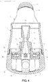
- a cap 7 is provided and the micro bubble generator 6 is entirely housed in the cap 7, so that it is possible to prevent injury of the head of a user, damage on the micro bubble generator 6 by dropping, or the like.
- Packings 5m and 6k are provided to seal gaps with the micro bubble generator 6 so that all of tap water can flow through the micro bubble generator 6, thereby preventing a loss of the water transferring pressure through a flow path.
- a shower head 1 capable of providing a shower feeling without a water spray plate according to the present invention includes a body 2, the bottom plate 3, the tornado plate 4, the pressing plate 5, the micro bubble generator 6, and the cap 7.
- the bottom plate 3 and the tornado plate 4 may be integrally formed, and the pressing plate 5 and the micro bubble generator 6 may be integrally formed.
- the tornado plate 4 can be replaced with that having a preferable helical angle, and the flow path of the micro bubble generator can be changed, depending on tap water pressure.
- Other components can be common components, and thus a manufacturing cost can be reduced. Accordingly, a highly general-purposed micro bubble generating shower head can be provided.
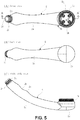
- the body 2 includes: the holding unit 2a suitable for holding by a hand; a first screw part 2d connected, by screwing, with a hose (not illustrated) through which tap water flows at one end of the holding unit 2a; the head unit 2e disposed at the other end of the holding unit 2a, including an opening 2f facing substantially at right angle to the holding unit 2a, and including a second screw part 2k at an outer periphery; a flow path 2i communicated from an end part of the first screw part 2d to the opening 2f through inside of the holding unit 2a and the head unit 2e; and a plurality of protrusions 2g each protruding from a bottom part of the head unit 2e and including a screw hole 2h inside.
- a packing 2m is fitted to the first screw part 2d, sealing a connection part with the hose.
- the holding unit 2a is suitable for holding and is provided with concavo-convex portions 2b and 2c serving as slip-proof portions.
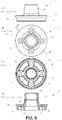
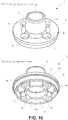
- the bottom plate 3 includes: a disk-shaped bottom part 3a including a through-hole 3c placed above each protrusion 2g of the head unit 2e and corresponding to the screw hole 2h of the protrusion 2g; a tubular inner rim 3g erected on an upper surface of the bottom part 3a, including a flow path 3b at a central part, and including inside a stepped portion 3i including a larger upper part and a smaller lower part; and an outer rim 3h erected at an outer periphery of the bottom part 3a.
- Protrusions 3d protrude on right and left sides of the through-hole 3c on the upper surface of the bottom part 3a, providing the strength of the bottom part 3a.
- a first ridge 3e circularly surrounding a bottom part of the inner rim 3g, and a second ridge 3f connected with the first ridge 3e and having a U shape surrounding the through-hole 3c are provided on a bottom surface of the bottom part 3a to prevent distortion of the bottom part 3a when the bottom plate 3 is removed from a mold after molding.
- the tornado plate 4 is housed in a portion having a larger diameter above the stepped portion 3i of the bottom plate 3 and locked by the stepped portion 3i. Then, as illustrated in, for example, Figures 3 and 4 , the pressing plate 5 on which the micro bubble generator 6 is mounted is fitted to the bottom part 3a between the inner rim 3g and the outer rim 3h on the upper surface of the bottom part 3a, and is fixed to the protrusions 2g inside the head unit 2e by a fastener 2n.
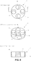
- the tornado plate 4 includes a disk-shaped body 4a, and four holes 4b vertically penetrating through the body 4a and eccentrically extending at, for example, 15 [degrees] to generate swirling flow by applying rotation to tap water and achieve an increased flow speed.
- the body 4a may be formed of, for example, resin by molding.
- the tornado plate 4 is locked to the stepped portion 3i inside the inner rim 3g of the bottom plate 3 and fitted inside the bottom plate 3.
- the pressing plate 5 includes a through-hole 5b corresponding to the through-hole 3c of the bottom plate 3 and the screw hole 2h of the protrusion 2g of the head unit 2e, a disk-shaped plate portion 5a including a hole 5d at a central part, a cylindrical portion 5c erected at a central part of an upper surface of the plate portion 5a and including the hole 5d and a first inner stepped portion 5i inside, an inner rim 5e erected and forming a second inner stepped portion 5k around the hole 5d on a bottom surface of the plate portion 5a, an outer rim 5f erected and forming a stepped portion 5g at an outer periphery of the bottom surface of the plate portion 5a, and a ridge 5h erected around the through-hole 5b and protruding to a height same as that of the outer rim 5f.
- the ridge 5h forms the through-hole 5b, maintaining strength there.
- a first ridge 6g of the micro bubble generator 6 is locked to the first inner stepped portion 5i.
- the inner rim 3g of the bottom plate 3 is locked to the second inner stepped portion 5k.
- the inner rim 5e and the outer rim 5f are fitted to the bottom part 3a of the bottom plate 3.
- the packing 5m is fitted to the stepped portion 5g, sealing a gap between the pressing plate 5 and the head unit 2e.
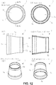
- the micro bubble generator 6 includes: a first cylindrical portion 6a housed inside the hole 5d of the pressing plate 5, including a first flow path 6b having an inner diameter gradually decreasing toward a central part from an end part through which tap water enters, and provided with, on an outer circumferential surface, a second ridge 6h at the end part, the first ridge 6g closer to the central part than the second ridge 6h, and a groove 6i as a recess between the second ridge 6h and the first ridge 6g; a second cylindrical portion 6c including a second flow path 6d connected with the first flow path 6b; and a third cylindrical portion 6e including a third flow path 6f connected with the second flow path 6d and having an inner diameter gradually increasing toward an end part through which the tap water exits, the end part serving as the spray nozzle 6m through which the tap water is discharged as a shower.
- the first ridge 6g is locked to the first inner stepped portion 5i of the pressing plate 5, and the packing 6k is fitted to the groove 6i, sealing a gap between the pressing plate 5 and the micro bubble generator 6.
- the tornado plate 4 is locked to the second ridge 6h, and the pressing plate 5 is fixed to the screw hole 2h of the protrusion 2g of the head unit 2e by the fastener 2n, thereby fixing the positions of the micro bubble generator 6 and the tornado plate 4.
- the tap water discharged from the spray nozzle 6m is formed into a shower or spray form along the shapes of the tornado plate 4 and the micro bubble generator 6 without a water spray plate, allowing a user to obtain a shower feeling similarly to that obtained from typical shower water.
- the cap 7 includes: a tubular body 7a including an internal hollow space 7e, and openings 7c and 7d at both ends, and having a smaller diameter toward a shower discharging side; a screw part 7b provided inside at one end on a side opposite to the discharging side; and a screw part 7f provided outside on the discharging side.
- the screw part 7b is connected, by screwing, with the second screw part 2k of the head unit 2e of the body 2, and houses the micro bubble generator 6 in the internal hollow space 7e.
- the cap 7 has a length longer than that of the micro bubble generator 6. This configuration prevents the micro bubble generator 6 from causing injury by hitting the head of the user, or being damaged by hitting, for example, a floor.
- the shower head 1 capable of providing a shower feeling without a water spray plate is easy to hold, configured to generate micro bubbles from tap water without taking in external air and injecting the air into the tap water, pressurizing the tap water at high pressure, nor performing any other special processing for micro bubble generation, and is also easy to assemble.
- the shower head according to the present application has such a structure that can provide a shower feeling without a water spray plate but allows attachment of a water spray plate in a case of high water supply pressure or in need of a weaker shower feeling.
- a mesh net may be detachably fixed to a leading end part of the cap 7 by screwing to achieve a reduced shower pressure.
- a mesh net having a wire diameter of 20 and a pitch of 40 is attached, shower is discharged in droplets, not in lines, and a desirable micro bubble shower pressure can be obtained.
- Such a mesh net is usually not recognized as a water spray plate of a shower head.
Landscapes
- Health & Medical Sciences (AREA)
- Life Sciences & Earth Sciences (AREA)
- Engineering & Computer Science (AREA)
- Hydrology & Water Resources (AREA)
- Public Health (AREA)
- Water Supply & Treatment (AREA)
- Nozzles (AREA)
- Bathtubs, Showers, And Their Attachments (AREA)
Applications Claiming Priority (2)
| Application Number | Priority Date | Filing Date | Title |
|---|---|---|---|
| JP2014123636A JP6358613B2 (ja) | 2014-06-16 | 2014-06-16 | 散水板を備えなくてもシャワー体感を得られるシャワーヘッド |
| PCT/JP2015/067308 WO2015194551A1 (ja) | 2014-06-16 | 2015-06-16 | 散水板を備えなくてもシャワー体感を得られるシャワーヘッド |
Publications (3)
| Publication Number | Publication Date |
|---|---|
| EP3189757A1 EP3189757A1 (en) | 2017-07-12 |
| EP3189757A4 EP3189757A4 (en) | 2017-11-01 |
| EP3189757B1 true EP3189757B1 (en) | 2018-05-16 |
Family
ID=54935534
Family Applications (1)
| Application Number | Title | Priority Date | Filing Date |
|---|---|---|---|
| EP15809544.8A Active EP3189757B1 (en) | 2014-06-16 | 2015-06-16 | Shower head with which shower sensations can be obtained without providing water sprinkling plate |
Country Status (5)
| Country | Link |
|---|---|
| US (1) | US10124363B2 (enExample) |
| EP (1) | EP3189757B1 (enExample) |
| JP (1) | JP6358613B2 (enExample) |
| CN (1) | CN106455872B (enExample) |
| WO (1) | WO2015194551A1 (enExample) |
Families Citing this family (11)
| Publication number | Priority date | Publication date | Assignee | Title |
|---|---|---|---|---|
| JP6570474B2 (ja) * | 2016-04-05 | 2019-09-04 | 株式会社micro−bub | 首振パイプ付き蛇口用マイクロバブル生成器及び首振パイプ付き蛇口 |
| JP6579547B2 (ja) * | 2016-07-12 | 2019-09-25 | 株式会社micro−bub | 蛇口用マイクロバブル生成器及びマイクロバブル生成器を内蔵した蛇口 |
| JP7012482B2 (ja) | 2017-08-02 | 2022-01-28 | 株式会社富士計器 | 微細気泡水生成器 |
| CN107542129A (zh) * | 2017-10-20 | 2018-01-05 | 开平市祺龙五金塑胶有限公司 | 一种水龙头起泡器 |
| JP6775552B2 (ja) | 2018-07-20 | 2020-10-28 | 株式会社サイエンス | シャワーヘッド、及び気泡発生ユニット |
| JP6990887B2 (ja) * | 2019-01-31 | 2022-01-12 | パナソニックIpマネジメント株式会社 | 散水板およびシャワー装置 |
| CN114192292B (zh) * | 2020-08-26 | 2023-09-22 | 无锡小天鹅电器有限公司 | 喷淋装置和洗涤系统 |
| JP7577305B2 (ja) * | 2020-10-14 | 2024-11-05 | 株式会社タカギ | 吐水部材及び吐水部材を備えた吐水装置 |
| JP2023026130A (ja) * | 2021-08-12 | 2023-02-24 | 株式会社micro-bub | マイクロバブル生成ホース |
| CN216573651U (zh) * | 2021-09-26 | 2022-05-24 | 康丽根水处理科技(上海)有限公司 | 一种喷雾花洒 |
| CN113926601B (zh) * | 2021-10-28 | 2022-11-04 | 重庆市生态环境科学研究院 | 微纳米气泡空化喷嘴 |
Family Cites Families (12)
| Publication number | Priority date | Publication date | Assignee | Title |
|---|---|---|---|---|
| US4497444A (en) * | 1982-10-28 | 1985-02-05 | Beatrice Foods Company | Shower head |
| WO1997024969A1 (en) * | 1996-01-03 | 1997-07-17 | Alfredo Espinosa Macin | Water conserving low pressure shower head |
| EP0856691B1 (en) * | 1996-08-19 | 2003-04-09 | Masahiro Hirata | Constant flowrate water saving valve and shower head using same |
| JP3100357B2 (ja) * | 1997-08-11 | 2000-10-16 | 洋史 大熊 | シャワーヘッド |
| JP2003326198A (ja) * | 2002-05-10 | 2003-11-18 | Masahiro Hirata | シャワーヘッド |
| JP2004136085A (ja) * | 2002-09-27 | 2004-05-13 | Toto Ltd | マッサージノズル及びマッサージシステム |
| DE202005004182U1 (de) * | 2005-03-14 | 2005-06-02 | Ilisin, Mile | Duschkopf |
| KR100674159B1 (ko) * | 2005-03-15 | 2007-01-24 | 요지 오쿠마 | 샤워 헤드 |
| JP2007050341A (ja) * | 2005-08-18 | 2007-03-01 | Matsushita Electric Ind Co Ltd | 微細気泡発生装置とそれを用いたシャワー装置 |
| CN201145092Y (zh) * | 2007-08-22 | 2008-11-05 | 沈祖平 | 节水型水龙头出水装置 |
| JP5755410B2 (ja) * | 2010-03-05 | 2015-07-29 | 市澤 順一 | 散水板を備えないシャワーヘッド |
| KR20140048940A (ko) * | 2011-07-21 | 2014-04-24 | 가부시키가이샤 시바타 | 기포발생기구 및 기포발생기구 부착 샤워헤드 |
-
2014
- 2014-06-16 JP JP2014123636A patent/JP6358613B2/ja active Active
-
2015
- 2015-06-16 CN CN201580032506.3A patent/CN106455872B/zh active Active
- 2015-06-16 WO PCT/JP2015/067308 patent/WO2015194551A1/ja not_active Ceased
- 2015-06-16 EP EP15809544.8A patent/EP3189757B1/en active Active
-
2016
- 2016-12-15 US US15/379,814 patent/US10124363B2/en active Active
Non-Patent Citations (1)
| Title |
|---|
| None * |
Also Published As
| Publication number | Publication date |
|---|---|
| WO2015194551A1 (ja) | 2015-12-23 |
| EP3189757A4 (en) | 2017-11-01 |
| EP3189757A1 (en) | 2017-07-12 |
| US10124363B2 (en) | 2018-11-13 |
| CN106455872A (zh) | 2017-02-22 |
| JP2016002196A (ja) | 2016-01-12 |
| JP6358613B2 (ja) | 2018-07-18 |
| US20170157635A1 (en) | 2017-06-08 |
| CN106455872B (zh) | 2019-03-29 |
Similar Documents
| Publication | Publication Date | Title |
|---|---|---|
| EP3189757B1 (en) | Shower head with which shower sensations can be obtained without providing water sprinkling plate | |
| CN109382013B (zh) | 微细气泡水生成器 | |
| US9322152B2 (en) | Shower head | |
| JP6210846B2 (ja) | マイクロバブルスプレー装置 | |
| JP6570474B2 (ja) | 首振パイプ付き蛇口用マイクロバブル生成器及び首振パイプ付き蛇口 | |
| KR101483412B1 (ko) | 마이크로 버블 노즐 | |
| JP6579547B2 (ja) | 蛇口用マイクロバブル生成器及びマイクロバブル生成器を内蔵した蛇口 | |
| MY198295A (en) | Showerhead and Mist Generating Unit | |
| JP3213014U (ja) | 洗濯機用微細気泡水生成器 | |
| CN106881207B (zh) | 吐水装置 | |
| CN211772133U (zh) | 微气泡喷头及具有该微气泡喷头的洗涤设备 | |
| KR200449102Y1 (ko) | 마이크로 버블 노즐 | |
| JP3208970U (ja) | シャワーヘッド用アスピレータ装置 | |
| KR100902136B1 (ko) | 마이크로 기포 발생장치 및 이를 이용한 욕조 시스템 | |
| CN211395015U (zh) | 微气泡喷头及具有该微气泡喷头的洗涤设备 | |
| JP6502024B2 (ja) | バブル発生装置付吐水器および吐水器用バブル発生アダプター | |
| KR20160038528A (ko) | 탄산수 제조용 혼합장치 | |
| JP3211585U (ja) | シャワーヘッド装置 | |
| CN114250832B (zh) | 出水装置及出水设备 | |
| JP2007326082A (ja) | シャワーヘッド | |
| CN210115170U (zh) | 一种纳米气泡莲蓬头 | |
| CN109519135A (zh) | 一种泡沫发生器 | |
| KR101484668B1 (ko) | 무동력 미세기포 발생장치 | |
| JP2011183125A (ja) | シャワーホースの先に接続する吐水口部の構造 | |
| JP5961204B2 (ja) | ミスト散水装置 |
Legal Events
| Date | Code | Title | Description |
|---|---|---|---|
| STAA | Information on the status of an ep patent application or granted ep patent |
Free format text: STATUS: THE INTERNATIONAL PUBLICATION HAS BEEN MADE |
|
| PUAI | Public reference made under article 153(3) epc to a published international application that has entered the european phase |
Free format text: ORIGINAL CODE: 0009012 |
|
| STAA | Information on the status of an ep patent application or granted ep patent |
Free format text: STATUS: REQUEST FOR EXAMINATION WAS MADE |
|
| 17P | Request for examination filed |
Effective date: 20170426 |
|
| AK | Designated contracting states |
Kind code of ref document: A1 Designated state(s): AL AT BE BG CH CY CZ DE DK EE ES FI FR GB GR HR HU IE IS IT LI LT LU LV MC MK MT NL NO PL PT RO RS SE SI SK SM TR |
|
| AX | Request for extension of the european patent |
Extension state: BA ME |
|
| DAV | Request for validation of the european patent (deleted) | ||
| DAX | Request for extension of the european patent (deleted) | ||
| A4 | Supplementary search report drawn up and despatched |
Effective date: 20171005 |
|
| RIC1 | Information provided on ipc code assigned before grant |
Ipc: E03C 1/04 20060101ALI20170928BHEP Ipc: B05B 1/18 20060101ALI20170928BHEP Ipc: B05B 1/34 20060101ALI20170928BHEP Ipc: A47K 3/28 20060101AFI20170928BHEP Ipc: B05B 1/02 20060101ALI20170928BHEP |
|
| GRAP | Despatch of communication of intention to grant a patent |
Free format text: ORIGINAL CODE: EPIDOSNIGR1 |
|
| STAA | Information on the status of an ep patent application or granted ep patent |
Free format text: STATUS: GRANT OF PATENT IS INTENDED |
|
| INTG | Intention to grant announced |
Effective date: 20171205 |
|
| GRAS | Grant fee paid |
Free format text: ORIGINAL CODE: EPIDOSNIGR3 |
|
| GRAA | (expected) grant |
Free format text: ORIGINAL CODE: 0009210 |
|
| STAA | Information on the status of an ep patent application or granted ep patent |
Free format text: STATUS: THE PATENT HAS BEEN GRANTED |
|
| AK | Designated contracting states |
Kind code of ref document: B1 Designated state(s): AL AT BE BG CH CY CZ DE DK EE ES FI FR GB GR HR HU IE IS IT LI LT LU LV MC MK MT NL NO PL PT RO RS SE SI SK SM TR |
|
| REG | Reference to a national code |
Ref country code: GB Ref legal event code: FG4D |
|
| REG | Reference to a national code |
Ref country code: CH Ref legal event code: EP |
|
| REG | Reference to a national code |
Ref country code: IE Ref legal event code: FG4D |
|
| REG | Reference to a national code |
Ref country code: DE Ref legal event code: R096 Ref document number: 602015011307 Country of ref document: DE |
|
| REG | Reference to a national code |
Ref country code: AT Ref legal event code: REF Ref document number: 998775 Country of ref document: AT Kind code of ref document: T Effective date: 20180615 |
|
| REG | Reference to a national code |
Ref country code: NL Ref legal event code: MP Effective date: 20180516 |
|
| REG | Reference to a national code |
Ref country code: LT Ref legal event code: MG4D |
|
| PG25 | Lapsed in a contracting state [announced via postgrant information from national office to epo] |
Ref country code: SE Free format text: LAPSE BECAUSE OF FAILURE TO SUBMIT A TRANSLATION OF THE DESCRIPTION OR TO PAY THE FEE WITHIN THE PRESCRIBED TIME-LIMIT Effective date: 20180516 Ref country code: BG Free format text: LAPSE BECAUSE OF FAILURE TO SUBMIT A TRANSLATION OF THE DESCRIPTION OR TO PAY THE FEE WITHIN THE PRESCRIBED TIME-LIMIT Effective date: 20180816 Ref country code: NO Free format text: LAPSE BECAUSE OF FAILURE TO SUBMIT A TRANSLATION OF THE DESCRIPTION OR TO PAY THE FEE WITHIN THE PRESCRIBED TIME-LIMIT Effective date: 20180816 Ref country code: FI Free format text: LAPSE BECAUSE OF FAILURE TO SUBMIT A TRANSLATION OF THE DESCRIPTION OR TO PAY THE FEE WITHIN THE PRESCRIBED TIME-LIMIT Effective date: 20180516 Ref country code: LT Free format text: LAPSE BECAUSE OF FAILURE TO SUBMIT A TRANSLATION OF THE DESCRIPTION OR TO PAY THE FEE WITHIN THE PRESCRIBED TIME-LIMIT Effective date: 20180516 Ref country code: ES Free format text: LAPSE BECAUSE OF FAILURE TO SUBMIT A TRANSLATION OF THE DESCRIPTION OR TO PAY THE FEE WITHIN THE PRESCRIBED TIME-LIMIT Effective date: 20180516 |
|
| PG25 | Lapsed in a contracting state [announced via postgrant information from national office to epo] |
Ref country code: HR Free format text: LAPSE BECAUSE OF FAILURE TO SUBMIT A TRANSLATION OF THE DESCRIPTION OR TO PAY THE FEE WITHIN THE PRESCRIBED TIME-LIMIT Effective date: 20180516 Ref country code: GR Free format text: LAPSE BECAUSE OF FAILURE TO SUBMIT A TRANSLATION OF THE DESCRIPTION OR TO PAY THE FEE WITHIN THE PRESCRIBED TIME-LIMIT Effective date: 20180817 Ref country code: NL Free format text: LAPSE BECAUSE OF FAILURE TO SUBMIT A TRANSLATION OF THE DESCRIPTION OR TO PAY THE FEE WITHIN THE PRESCRIBED TIME-LIMIT Effective date: 20180516 Ref country code: LV Free format text: LAPSE BECAUSE OF FAILURE TO SUBMIT A TRANSLATION OF THE DESCRIPTION OR TO PAY THE FEE WITHIN THE PRESCRIBED TIME-LIMIT Effective date: 20180516 Ref country code: RS Free format text: LAPSE BECAUSE OF FAILURE TO SUBMIT A TRANSLATION OF THE DESCRIPTION OR TO PAY THE FEE WITHIN THE PRESCRIBED TIME-LIMIT Effective date: 20180516 |
|
| REG | Reference to a national code |
Ref country code: AT Ref legal event code: MK05 Ref document number: 998775 Country of ref document: AT Kind code of ref document: T Effective date: 20180516 |
|
| PG25 | Lapsed in a contracting state [announced via postgrant information from national office to epo] |
Ref country code: SK Free format text: LAPSE BECAUSE OF FAILURE TO SUBMIT A TRANSLATION OF THE DESCRIPTION OR TO PAY THE FEE WITHIN THE PRESCRIBED TIME-LIMIT Effective date: 20180516 Ref country code: RO Free format text: LAPSE BECAUSE OF FAILURE TO SUBMIT A TRANSLATION OF THE DESCRIPTION OR TO PAY THE FEE WITHIN THE PRESCRIBED TIME-LIMIT Effective date: 20180516 Ref country code: CZ Free format text: LAPSE BECAUSE OF FAILURE TO SUBMIT A TRANSLATION OF THE DESCRIPTION OR TO PAY THE FEE WITHIN THE PRESCRIBED TIME-LIMIT Effective date: 20180516 Ref country code: EE Free format text: LAPSE BECAUSE OF FAILURE TO SUBMIT A TRANSLATION OF THE DESCRIPTION OR TO PAY THE FEE WITHIN THE PRESCRIBED TIME-LIMIT Effective date: 20180516 Ref country code: AT Free format text: LAPSE BECAUSE OF FAILURE TO SUBMIT A TRANSLATION OF THE DESCRIPTION OR TO PAY THE FEE WITHIN THE PRESCRIBED TIME-LIMIT Effective date: 20180516 Ref country code: DK Free format text: LAPSE BECAUSE OF FAILURE TO SUBMIT A TRANSLATION OF THE DESCRIPTION OR TO PAY THE FEE WITHIN THE PRESCRIBED TIME-LIMIT Effective date: 20180516 Ref country code: PL Free format text: LAPSE BECAUSE OF FAILURE TO SUBMIT A TRANSLATION OF THE DESCRIPTION OR TO PAY THE FEE WITHIN THE PRESCRIBED TIME-LIMIT Effective date: 20180516 |
|
| REG | Reference to a national code |
Ref country code: CH Ref legal event code: PL |
|
| REG | Reference to a national code |
Ref country code: DE Ref legal event code: R097 Ref document number: 602015011307 Country of ref document: DE |
|
| PG25 | Lapsed in a contracting state [announced via postgrant information from national office to epo] |
Ref country code: SM Free format text: LAPSE BECAUSE OF FAILURE TO SUBMIT A TRANSLATION OF THE DESCRIPTION OR TO PAY THE FEE WITHIN THE PRESCRIBED TIME-LIMIT Effective date: 20180516 Ref country code: IT Free format text: LAPSE BECAUSE OF FAILURE TO SUBMIT A TRANSLATION OF THE DESCRIPTION OR TO PAY THE FEE WITHIN THE PRESCRIBED TIME-LIMIT Effective date: 20180516 |
|
| REG | Reference to a national code |
Ref country code: BE Ref legal event code: MM Effective date: 20180630 |
|
| REG | Reference to a national code |
Ref country code: IE Ref legal event code: MM4A |
|
| PLBE | No opposition filed within time limit |
Free format text: ORIGINAL CODE: 0009261 |
|
| STAA | Information on the status of an ep patent application or granted ep patent |
Free format text: STATUS: NO OPPOSITION FILED WITHIN TIME LIMIT |
|
| PG25 | Lapsed in a contracting state [announced via postgrant information from national office to epo] |
Ref country code: LU Free format text: LAPSE BECAUSE OF NON-PAYMENT OF DUE FEES Effective date: 20180616 Ref country code: MC Free format text: LAPSE BECAUSE OF FAILURE TO SUBMIT A TRANSLATION OF THE DESCRIPTION OR TO PAY THE FEE WITHIN THE PRESCRIBED TIME-LIMIT Effective date: 20180516 |
|
| 26N | No opposition filed |
Effective date: 20190219 |
|
| PG25 | Lapsed in a contracting state [announced via postgrant information from national office to epo] |
Ref country code: FR Free format text: LAPSE BECAUSE OF NON-PAYMENT OF DUE FEES Effective date: 20180716 Ref country code: LI Free format text: LAPSE BECAUSE OF NON-PAYMENT OF DUE FEES Effective date: 20180630 Ref country code: CH Free format text: LAPSE BECAUSE OF NON-PAYMENT OF DUE FEES Effective date: 20180630 Ref country code: IE Free format text: LAPSE BECAUSE OF NON-PAYMENT OF DUE FEES Effective date: 20180616 |
|
| PG25 | Lapsed in a contracting state [announced via postgrant information from national office to epo] |
Ref country code: BE Free format text: LAPSE BECAUSE OF NON-PAYMENT OF DUE FEES Effective date: 20180630 |
|
| PG25 | Lapsed in a contracting state [announced via postgrant information from national office to epo] |
Ref country code: AL Free format text: LAPSE BECAUSE OF FAILURE TO SUBMIT A TRANSLATION OF THE DESCRIPTION OR TO PAY THE FEE WITHIN THE PRESCRIBED TIME-LIMIT Effective date: 20180516 |
|
| PG25 | Lapsed in a contracting state [announced via postgrant information from national office to epo] |
Ref country code: MT Free format text: LAPSE BECAUSE OF NON-PAYMENT OF DUE FEES Effective date: 20180616 |
|
| PG25 | Lapsed in a contracting state [announced via postgrant information from national office to epo] |
Ref country code: TR Free format text: LAPSE BECAUSE OF FAILURE TO SUBMIT A TRANSLATION OF THE DESCRIPTION OR TO PAY THE FEE WITHIN THE PRESCRIBED TIME-LIMIT Effective date: 20180516 |
|
| PG25 | Lapsed in a contracting state [announced via postgrant information from national office to epo] |
Ref country code: PT Free format text: LAPSE BECAUSE OF FAILURE TO SUBMIT A TRANSLATION OF THE DESCRIPTION OR TO PAY THE FEE WITHIN THE PRESCRIBED TIME-LIMIT Effective date: 20180516 |
|
| PG25 | Lapsed in a contracting state [announced via postgrant information from national office to epo] |
Ref country code: MK Free format text: LAPSE BECAUSE OF NON-PAYMENT OF DUE FEES Effective date: 20180516 Ref country code: CY Free format text: LAPSE BECAUSE OF FAILURE TO SUBMIT A TRANSLATION OF THE DESCRIPTION OR TO PAY THE FEE WITHIN THE PRESCRIBED TIME-LIMIT Effective date: 20180516 Ref country code: HU Free format text: LAPSE BECAUSE OF FAILURE TO SUBMIT A TRANSLATION OF THE DESCRIPTION OR TO PAY THE FEE WITHIN THE PRESCRIBED TIME-LIMIT; INVALID AB INITIO Effective date: 20150616 |
|
| PG25 | Lapsed in a contracting state [announced via postgrant information from national office to epo] |
Ref country code: IS Free format text: LAPSE BECAUSE OF FAILURE TO SUBMIT A TRANSLATION OF THE DESCRIPTION OR TO PAY THE FEE WITHIN THE PRESCRIBED TIME-LIMIT Effective date: 20180916 |
|
| PG25 | Lapsed in a contracting state [announced via postgrant information from national office to epo] |
Ref country code: SI Free format text: LAPSE BECAUSE OF NON-PAYMENT OF DUE FEES Effective date: 20180616 |
|
| PGFP | Annual fee paid to national office [announced via postgrant information from national office to epo] |
Ref country code: DE Payment date: 20250618 Year of fee payment: 11 |
|
| PGFP | Annual fee paid to national office [announced via postgrant information from national office to epo] |
Ref country code: GB Payment date: 20250618 Year of fee payment: 11 |