EP3189281B1 - Four de cuisson avec un générateur de vapeur integré - Google Patents
Four de cuisson avec un générateur de vapeur integré Download PDFInfo
- Publication number
- EP3189281B1 EP3189281B1 EP14758583.0A EP14758583A EP3189281B1 EP 3189281 B1 EP3189281 B1 EP 3189281B1 EP 14758583 A EP14758583 A EP 14758583A EP 3189281 B1 EP3189281 B1 EP 3189281B1
- Authority
- EP
- European Patent Office
- Prior art keywords
- cavity
- evaporation
- oven
- heating element
- heater loop
- Prior art date
- Legal status (The legal status is an assumption and is not a legal conclusion. Google has not performed a legal analysis and makes no representation as to the accuracy of the status listed.)
- Active
Links
- XLYOFNOQVPJJNP-UHFFFAOYSA-N water Substances O XLYOFNOQVPJJNP-UHFFFAOYSA-N 0.000 title claims description 24
- 238000001704 evaporation Methods 0.000 claims description 140
- 230000008020 evaporation Effects 0.000 claims description 139
- 238000010438 heat treatment Methods 0.000 claims description 76
- 239000002184 metal Substances 0.000 claims description 8
- 238000010411 cooking Methods 0.000 claims description 7
- 230000004913 activation Effects 0.000 claims description 5
- 230000000694 effects Effects 0.000 claims description 3
- 210000003298 dental enamel Anatomy 0.000 description 9
- 239000002320 enamel (paints) Substances 0.000 description 9
- 239000007769 metal material Substances 0.000 description 5
- 229910000831 Steel Inorganic materials 0.000 description 3
- 230000009471 action Effects 0.000 description 3
- 230000015572 biosynthetic process Effects 0.000 description 3
- 238000000034 method Methods 0.000 description 3
- 239000010959 steel Substances 0.000 description 3
- 230000035882 stress Effects 0.000 description 3
- 230000002459 sustained effect Effects 0.000 description 3
- 230000008646 thermal stress Effects 0.000 description 3
- 238000009833 condensation Methods 0.000 description 2
- 230000005494 condensation Effects 0.000 description 2
- 238000010586 diagram Methods 0.000 description 2
- 238000009434 installation Methods 0.000 description 2
- 238000009413 insulation Methods 0.000 description 2
- 230000010354 integration Effects 0.000 description 2
- 238000004519 manufacturing process Methods 0.000 description 2
- 239000000463 material Substances 0.000 description 2
- 230000008569 process Effects 0.000 description 2
- 230000002035 prolonged effect Effects 0.000 description 2
- 230000002787 reinforcement Effects 0.000 description 2
- 238000000926 separation method Methods 0.000 description 2
- 235000019738 Limestone Nutrition 0.000 description 1
- 230000008901 benefit Effects 0.000 description 1
- 238000004140 cleaning Methods 0.000 description 1
- 230000007797 corrosion Effects 0.000 description 1
- 238000005260 corrosion Methods 0.000 description 1
- 230000001419 dependent effect Effects 0.000 description 1
- 238000007599 discharging Methods 0.000 description 1
- 238000009826 distribution Methods 0.000 description 1
- 238000005265 energy consumption Methods 0.000 description 1
- 239000002657 fibrous material Substances 0.000 description 1
- 239000008236 heating water Substances 0.000 description 1
- 238000003780 insertion Methods 0.000 description 1
- 230000037431 insertion Effects 0.000 description 1
- 239000006028 limestone Substances 0.000 description 1
- 238000013021 overheating Methods 0.000 description 1
- 230000001737 promoting effect Effects 0.000 description 1
- 230000009467 reduction Effects 0.000 description 1
- 230000003014 reinforcing effect Effects 0.000 description 1
- 230000004044 response Effects 0.000 description 1
- 238000007493 shaping process Methods 0.000 description 1
- 239000007787 solid Substances 0.000 description 1
- 238000003860 storage Methods 0.000 description 1
- 238000010792 warming Methods 0.000 description 1
Images


Classifications
-
- F—MECHANICAL ENGINEERING; LIGHTING; HEATING; WEAPONS; BLASTING
- F24—HEATING; RANGES; VENTILATING
- F24C—DOMESTIC STOVES OR RANGES ; DETAILS OF DOMESTIC STOVES OR RANGES, OF GENERAL APPLICATION
- F24C15/00—Details
- F24C15/32—Arrangements of ducts for hot gases, e.g. in or around baking ovens
- F24C15/322—Arrangements of ducts for hot gases, e.g. in or around baking ovens with forced circulation
- F24C15/327—Arrangements of ducts for hot gases, e.g. in or around baking ovens with forced circulation with air moisturising
-
- F—MECHANICAL ENGINEERING; LIGHTING; HEATING; WEAPONS; BLASTING
- F24—HEATING; RANGES; VENTILATING
- F24C—DOMESTIC STOVES OR RANGES ; DETAILS OF DOMESTIC STOVES OR RANGES, OF GENERAL APPLICATION
- F24C15/00—Details
- F24C15/003—Details moisturising of air
Definitions
- the present invention relates to an oven according to the preamble of claim 1.
- Known household ovens comprise a cavity with a closable opening for receiving food to be cooked wherein the oven cavity is made of metal parts or sheets which are welded together to create the cavity.
- the internal sides of the cavity are often enameled.
- Heating elements are provided for heating the cavity. Top and grill heating elements are placed inside the cavity in the upper region, a ring heating element surrounds a convection cooking fan, whereas bottom heating elements are placed outside and underneath the cavity.
- EP 0 279 065 A2 discloses an oven comprising in addition a steam generator.
- the steam generator comprises a pot which is mounted into an opening in the bottom wall of the oven cavity.
- a heating element is provided for heating water that is filled into the pot in order to generate steam which enters the oven cavity.
- DE 10 2010 029 326 A1 discloses a domestic appliance for preparing food that comprises a muffle a container for water positioned on a bottom wall of the muffle and a heating installation arranged below the bottom wall of the muffle, wherein the heating installation is formed as a two-circeled heater tube.
- the invention is defined in claim 1.
- the evaporation cavity is formed as an embossment in the bottom wall of the oven cavity, and the evaporation cavity has a maximum volume that is limited by the formation of the evaporation cavity as an embossment in the bottom wall of the oven cavity.
- An advantage of an oven according to the present invention is the fact that such an oven is easy to produce and does not require complicated procedures during assembly. This is based on the fact that the evaporation cavity is a deep drawn impression in the bottom of the oven cavity. Such a deep drawing process is less complex and less expensive than the integration of a separate pot into the bottom of the oven cavity.
- the evaporation cavity can be defined during the deep drawing simultaneously with other reinforcement structures (against buckling) and can act itself as such a reinforcement structure since such an embossment also reinforces the bottom of the oven cavity against buckling issues.
- the resulting evaporation cavity can be cleaned easily since it is integrated in one piece and hence in a seamless manner into the bottom wall of the oven cavity.
- the volume of an embossment in the bottom of the oven cavity is smaller than the volume of known evaporation cavities.
- the evaporation cavity is integrally formed into the bottom wall of the oven cavity wherein the bottom wall of the oven cavity preferably is a sheet of metal and the evaporation cavity is embossed into this metal sheet.
- the oven cavity is made out of a formed metal sheet, in one or more parts assembled together, and a layer of enamel is applied on the inner surface, to protect against corrosion, enhance cleanability, and give an highly aesthetic finish to the surface.
- Direct storage of the water in the embossment also allows ensuring condensation reflow in the embossment itself, which is helped by the typical shape of a cavity bottom including the embossment itself.
- the evaporation heating element has a maximum heating power that is adapted to heat a volume of water to be evaporated that corresponds to the volume of said evaporation cavity.
- a maximum heating power that is adapted to heat a volume of water to be evaporated that corresponds to the volume of said evaporation cavity.
- an evaporation heating element with reduced power can be used.
- the power of the evaporation heating element can be selected to be specific to, or otherwise correspond to the volume of the evaporation cavity.
- an evaporation cavity according to the present invention which has a volume which is limited by its formation as an embossment in the bottom wall of the oven cavity, and in particular said evaporation cavity with an evaporation heating element with a corresponding power, cannot only be used as primary steam generator in case only a smaller amount of steam is required but also as a supplementary evaporator in case that a primary steam generator with a separate water source independent of the evaporation cavity is already provided.
- it can also be used in combination with a primary steam generator as a condensate evaporator only where condensed water shall be re-evaporated, or for baking or cooking where only a small amount of steam and humidity is desired.
- the evaporation heating element is provided in an area underneath the evaporation cavity, preferably without having a direct mechanical contact to the evaporation cavity. Avoiding a direct contact reduces the thermal stress applied to the bottom wall of the cavity and reduces the danger of damaging an enamel coating since hot spots and critical thermal gradients are avoided.
- the oven comprises a bottom heating element comprising a primary heater loop and a secondary heater loop, wherein the primary heater loop is arranged underneath the oven cavity in an area that at least partially surrounds the area underneath the evaporation cavity and the evaporation heating element comprises said secondary heater loop, wherein the primary heater loop at least partially surrounds the secondary heater loop.
- bottom heat and evaporation are induced and controlled by different heater loops.
- This configuration allows to have the oven performing standard cooking operations (as in a standard oven equipped with a standard bottom heater) when the primary heater loop is activated and the secondary heater loop is inactive (e.g., in an off state).
- the primary heater loop and the secondary heater loop can be arranged between the bottom wall of the oven cavity including the evaporation cavity and a cover plate arranged vertically beneath and covering the heater loops.
- the bottom wall of the oven cavity and the cover plate hence define a box comprising the heater loops.
- This is particularly advantageous for the overall oven assembly process, and it allows a precise positioning of the loops in terms of distance from the bottom wall where a mandatory minimum distance is requested to ensure enamel integrity.
- an insulation blanket can be continuous (avoiding cutouts) and arranged outside and below the cover plate without touching or pushing the loops. This also ensures a more homogeneous irradiation, resulting in an even heat flow towards the whole cavity bottom. This effect is also based on reflection effects of the cover plate.
- the presence of the cover plate along with a continuous insulation blanket also minimizes the heat loss toward the outside of the cavity, optimizing the performances in terms of energy consumption.
- the primary heater loop and the secondary heater loop are arranged on two different, essentially parallel planes, such that both heater loops maintain essentially the same distance from the bottom wall of the oven cavity, respectively in the area surrounding the area underneath the evaporation cavity and in the area underneath the evaporation cavity.
- the primary heater loop and the secondary heater loop can preferably be arranged in a distance from the respective nearest point of the bottom wall of 5 to 25 mm, more preferably of 2 to 12 mm. This reflects a balance between the thermal stress applied to the bottom wall and a sufficient heat transfer.
- the primary heater loop and the secondary heater loop are controlled such that the primary heater loop can be activated together with or without the secondary heater loop.
- this offers the possibility to use the oven in a standard mode with bottom heat only (or in combination with other heating elements) with only the primary heater loop active or, alternatively, with additional steam generation with both the primary and secondary heater loops active.
- This possibility is vital to ensure a reliable operation of the oven, in particular for enameled oven cavities; the activation of the secondary loop, whose heating action is focused on the cavity bottom centre, could induce an uneven thermal field, particularly dangerous for the enamel layer, prone to crack where local deformations should occur due to temperature differences.
- a controller is operable to prevent operation of the secondary heater loop for sustained periods to evaporate water in the evaporation cavity while the primary heater loop is inactive.
- the heat distribution is evened over the whole cavity bottom, avoiding thermal gradients which could lead to enamel damages. It has to be clarified that the power output requested to the primary loop to perform the above mentioned warming action is much lower than the power output required for cooking functions, in a ratio between 1/2 to 1/10.
- a preferred way to achieve this contemporary activation of primary and secondary loop, having the former generating a reduced power output, is to have the primary heater loop and the secondary heater loop activated together by switching them into a series electrical connection, wherein the primary heater loop and the secondary heater loop preferably are in an ohmic value ratio between 1 to 0.2, wherein the secondary heating element has higher ohmic value.
- a primary loop capable of a 1kW power output is switched in series with a secondary loop having an ohmic value ratio of 1, would provide a power of 250W, as the secondary loop itself; for a nominal operating voltage of 230V, the ohmic value of both elements would correspond to 52W.
- a primary loop capable of a 2,4kW power output is switched in series with a secondary loop having an ohmic value ratio of 0.66, would provide a power of 400W, while the secondary loop would provide a power of 600W.
- the ohmic value of primary loop would correspond to 22W
- the secondary loop's one would correspond to 33W.
- the evaporation cavity is adapted to receive a volume of water to be evaporated which is preferably a volume between 10 and 300 ml, more preferably between 50 to 250 ml and the heating power of the evaporation heating element is adapted to evaporate such a volume of water.
- a volume of water to be evaporated which is preferably a volume between 10 and 300 ml, more preferably between 50 to 250 ml and the heating power of the evaporation heating element is adapted to evaporate such a volume of water.
- At least an area of the bottom wall adjacent to the evaporation cavity can have a down-grade towards the evaporation cavity in order to direct a condensate towards and into the evaporation cavity and / or to stiffen the bottom wall wherein preferably the angle of the down-grade is in a range between 1 and 7 degrees with respect to the horizontal.
- condensed water is guided towards the evaporation cavity and is evaporated again in order to control the humidity in the cavity or to maintain the bottom wall dry.
- the evaporation cavity preferably has a diameter between 5 cm to 25 cm, more preferably between 7 cm and 17 cm and / or the embossment of the evaporation cavity has a maximum depth between 2 and 20 mm, more preferably between 5 and 10 mm.
- the embossment defines the evaporation cavity by means of two consecutive bends leading to a downwardly orientated step in the bottom wall of the oven cavity wherein the bends have a respective radius between 5 and 20 mm, more preferably between 6 and 8 mm.
- Such radii turned out to provide a good base layer for enamel coatings since the risk of enamel damages is reduced. According edges are mild enough to prevent stresses on the enamel, avoid water flow blockage, and permit an effective cleaning action thanks to the absence of hindering areas where dirt or limestone can get stuck.
- the bottom wall of the oven cavity and the evaporation cavity are integrally formed as a monolithic, continuous sheet of metal or other suitable material. Integrally formed in such a manner, the evaporation cavity is not separable from the surrounding portion of the bottom wall of the oven cavity.
- a bottom of the evaporation cavity can have a down-grade towards a center of the bottom of the evaporation cavity. This stiffens the evaporation cavity and improves the flow of condensate towards the center of the cavity.
- the evaporation cavity or a bottom of the evaporation cavity is concave when seen from the inner side of the oven cavity, wherein preferably a curvature of the evaporation cavity or of the bottom of the evaporation cavity defines a radius between 200 and 500 cm, more preferably between 300 and 400 cm.
- a temperature sensor is provided which is adapted to measure the temperature in the area of the evaporation cavity and to preferably control an electrical power provided towards the evaporation heating element.
- evaporation cavity is provided with a dirt cover, permeable to steam and shaped to allow water and condensate flow from the cavity walls and bottom into the evaporation cavity.
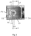
- Fig. 1 shows an oven comprising a cavity 10 with a closable opening 12 for receiving food to be cooked or baked within the oven cavity 10.
- the opening 12 can be closed by means of a front door 14.
- the oven cavity 10 is defined by sidewalls 16, a rear wall 18, a top wall 20 and a bottom wall 24.
- a top heating or grill element 22 is mounted in the upper region of the oven cavity 10.
- the bottom wall 24 comprises an evaporation cavity 26 which is a deep drawn embossment.
- the embossment defining the evaporation cavity 26 is worked into a steel sheet constituting the bottom wall 24 during a shaping operation where the bottom wall 24 of the oven cavity 10 is defined.
- rear wall 18 and top wall 20 are made of steel sheets and are enameled.
- An evaporation heating element 28 is provided for heating the evaporation cavity 26 in an area 29 underneath the evaporation cavity 26.
- the heating power of the evaporation heating element 28 is adapted to evaporate a volume of water to be evaporated that corresponds to the volume of the evaporation cavity 26.
- the evaporation cavity 26 together with the evaporation heating element 28 act as a steam generation system. Water can be conveyed into the evaporation cavity 26 either by direct pouring or by means of a pipe or a channel. By activation of the evaporation heating element 28 the water is evaporated.
- the evaporation heating element 28 is arranged in an area 29 underneath the evaporation cavity 26 and can be a second branch of an also provided standard bottom heating element with independent control. This will be explained in more detail in connection with the following Figures.
- the evaporation heating 28 element is self-supporting and not in direct contact with the bottom wall 24 and the embossment defining the evaporation cavity 26.
- such an evaporating heating element can be a heating device directly fixed onto the external surface of the embossment defining the evaporation cavity 26 (e.g. a standard heater, a thick film heater, welded, glued or fixed by other means directly onto the external surface of the evaporation cavity 26).
- a thermostat or temperature sensor 30 is applied to the external surface of the evaporation cavity 26 to prevent overheating (e.g. upon run-out of water) or to control the power delivery and hence the evaporation.
- the oven can also comprise a steam inlet 32 which is connected to an (not shown) external steam generator so that the evaporation cavity 26 together with the evaporation heating element 26 acts as auxiliary generator or condensation re-evaporator collecting condensate and reevaporating it.
- the evaporation cavity 26 and the evaporation heating element 28 can also be used as the only source of steam and / or humidity without an additional steam generator.
- the evaporation cavity 26 can be protected by a cover, shaped to fit onto it in order to prevent food debris to get in contact with the hot evaporation cavity 26 which would lead to cleanability issues. Since the evaporation cavity 26 is preferably designed to receive a volume of water between 10 and 300 ml, more preferably between 50 to 100 ml, the evaporation heating element 28 preferably provides a heating power between 300 and 800 W so as to be adapted to evaporate an according volume of water during a typical cooking or baking time.
- a user interface 38 is provided for controlling the oven.
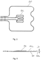
- Fig. 2 shows the oven of Fig. 1 in a sectional view from below.
- a cover plate which normally covers heater loops, is removed.
- the oven comprises an electrical bottom heating element 27 which in turn comprises a primary heater loop 40 for providing bottom heat to the oven cavity 10.
- This primary heater loop 40 is surrounded by a secondary electrical heater loop 42 which relates to the evaporation heating element 28.
- the secondary heater loop 42 is provided in an area 29 underneath the evaporation cavity 26 whereas the primary heater loop 40 is arranged in an area 31 that excludes the area 29 underneath the evaporation cavity 26.
- Primary heater loop 40 is arranged underneath the oven cavity 10 too.
- Figures 3 and 4 show a primary heater loop 40 and a secondary heater loop 42 which are arranged in two different, essentially parallel planes 40b and 42b, respectively.
- These heater loops 40 and 42 can be installed in the oven according to Figures 1 and 2 (where the corresponding loops 40 and 42 are shown more schematically).
- the assembly including the primary and secondary heater loops 40, 42 is shown in FIG. 4 upside down.
- the secondary heater loop 42 is arranged at an elevation that is lower than an elevation of a primary heating loop 40 by the distance D.
- the secondary heater loop 42 appears vertically above the primary heater loop 40.
- Both planes 40b and 42b are arranged in a distance D to each other wherein the plane 42b comprising the secondary heater loop 42 is above the plane 40b of the primary heater loop 40, wherein "above” refers to an assembled condition of the oven.
- the distance D between both planes 40b and 42b is such that both heater loops 40 and 42 maintain essentially the same distance from the bottom wall 24 of the oven cavity, respectively in the area 31 surrounding the area 29 underneath the evaporation cavity 26 and in the area 29 under the evaporation cavity 26.
- the separation S1 between the bottom of the area 31 surrounding the evaporation cavity 26 and the primary heater loop 40, and the separation S2 between the bottom of the evaporation cavity 26 and the secondary heater loop 42 is approximately the same.
- Fig. 5 shows the cavity bottom wall 24 with the evaporation cavity 26 the heater loops comprising the primary heater loop 40 and the secondary heater loop 42 and a cover plate 50 in an exploded view.
- the cover plate 50 is designed for protecting the primary heater loop 40 and the secondary heater loop 42.
- additional reinforcing structures 36 are embossed or deep drawn into the bottom wall 24.
- a heat insulating layer e.g. of a fibrous material will be arranged below the cover plate 50.
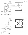
- Figs. 6 and 7 show a schematic connection diagram comprising the primary heater loop 40 and a secondary heater loop 42 of Figures 2 and 5 that are controllable by a controller 67.
- the controller 67 includes suitable electronic components and is otherwise adapted to issue control signals for establishing the operational modes of the oven described herein.
- a first end 42a of secondary heater loop 42 is electrically connected to electrical ground 64 pursuant to an instruction from the controller 67.
- a second end 42b of secondary heater loop 42 is connected to a first end 40a of primary heater loop 40 which in turn is also connected via a breaker 62 to electrical ground 66.
- a second end 40b of primary heater loop 40 is connected via breaker 68 to a source of electrical power 70.
- breaker 68 is closed (conducting) and breaker 62 is open, both heater loops 40 and 42 are switched into a series electrical connection and are activated by a current running from the source of electrical power 70 to electrical ground 64 to establish an operational mode of heat and steam.
- the controller 67 can be configured to operate the primary heater loop 40, without the secondary heater loop 42, and optionally in combination with another heater loop (e.g., convection heating element, broil heating element, etc...), or to operate both the primary heater loop 40 in combination (e.g., in series) with the secondary heater loop 42.
- the controller 67 can thus optionally prevent sustained operation of the secondary heater loop 42 without also requiring activation of the primary heater loop 40.
- FIG. 9 shows a schematic sectional view of the bottom wall 24 provided with an evaporation cavity and an enamel coating 25 arranged adjacent to the primary and secondary heater loops 40, 42 taken along line 9-9 in Fig. 2 .
- Points where the local temperatures discussed below are present are identified by temperatures T1, T2, T3 and T4.
- T1 represents the temperature of the enamel coating 25 adjacent to a central region at the bottom of the evaporation cavity 26.
- T2 represents the temperature of the metal material from which the bottom wall 24 was formed adjacent to a central region at the bottom of the evaporation cavity 26, opposite the location of the temperature T1.
- T3 represents the temperature of the metal material of the bottom wall 24 along an angled region between bends in the material to form the evaporation chamber 26.
- T4 represents the temperature of the metal material of the bottom wall 24 in a surrounding region of the bottom wall 24 that is substantially horizontal and located radially outward from the central region of the evaporation cavity 26, beyond the exterior periphery of the evaporation cavity 26.
- the oven in FIG. 9 is in the operational state prevented by the controller 67, where only the secondary heater loop 42 is active.
- the active, or operational heater loops are represented in FIGs. 9 and 10 by the solid-filled circles representing the cross section of the heater loops 40, 42, and the off heater loops are represented by open, or unfilled circles.
- Prolonged operation of the oven in the operational state represented in FIG. 9 can result in the following approximate, steady-state temperatures T1-T4 being established: Table 1: Temperature Gradients with Oven in Prevented Operational Mode T1 ⁇ 100°C T2 120 - 140°C T3 130 - 160°C T4 Room Temperature - 40°C
- the differences in temperature of the metal material forming the bottom wall 24 at T2, T3 and T4 can cause the metal material to expand to a different extent at each location. Such differences in expansion can exert significant stress on the enamel coating 25, thereby promoting the formation of cracks in, or otherwise damaging that enamel coating 25.
- the controller 67 is adapted to connect the primary and secondary heater loops 40, 42 in series during an operational mode of the oven that generates steam from the water in the evaporation cavity 26.
- the primary heater loop 40 is operational (i.e., on), but at a lower power output than a power output at which the primary heater loop 40 is operated when the oven is in a standard bake operational mode (when the primary heater loop 40 is operational but the secondary heater loop 42 is off, and steam is not being generated).
- a standard bake operational mode when the primary heater loop 40 is operational but the secondary heater loop 42 is off, and steam is not being generated.
- T1-T4 steady-state temperatures
- Table 2 Temperature Gradients with Oven in Enamel-Preserving Operational Mode T1 ⁇ 100°C T2 120 - 140°C T3 130 - 160°C T4 100 - 130°C
- the differences in temperature gradients that exist between T4 and T2 and T3 are much smaller than the corresponding temperature gradients present when the oven is operated in the operational mode represented in FIG. 9 .
- the temperature ranges for T2, T3 and T4 can optionally overlap.
- the smaller temperature gradients promote similar thermal expansion of the metal forming the bottom wall 24, thereby exerting less stress on the enamel coating 25.
Landscapes
- Engineering & Computer Science (AREA)
- Chemical & Material Sciences (AREA)
- Combustion & Propulsion (AREA)
- Mechanical Engineering (AREA)
- General Engineering & Computer Science (AREA)
- Electric Stoves And Ranges (AREA)
- Baking, Grill, Roasting (AREA)
Claims (15)
- Four comportant :une cavité (10) de four dotée d'une ouverture (12) pouvant être fermée, destinée à recevoir des aliments à cuire ou à étuver,une cavité (26) d'évaporation disposée dans une paroi inférieure (24) de la cavité (10) de four comme un renfoncement présentant un volume formé dans la paroi inférieure (24) de la cavité (10) de four,un élément chauffant inférieur (27) comportant une boucle primaire (40) de chauffe et un élément chauffant (28) d'évaporation comportant une boucle secondaire (42) de chauffe disposée pour chauffer la cavité (26) d'évaporation, la boucle primaire (40) de chauffe étant disposée sous la cavité (10) de four dans une zone (31) qui entoure au moins partiellement la zone (29) sous la cavité (26) d'évaporation, et la boucle primaire (40) de chauffe entourant au moins partiellement l'élément chauffant (28) d'évaporation,caractérisé parun moyen de commande configuré pour faire fonctionner sélectivement uniquement la boucle primaire (40) de chauffe, ou faire fonctionner simultanément la boucle primaire (40) de chauffe et l'élément chauffant (28) d'évaporation en commutant la boucle primaire de chauffe (40) et l'élément chauffant (28) d'évaporation vers un branchement électrique en série, la puissance en sortie de la boucle primaire (40) se situant dans un rapport de 1/2 à 1/10 de la puissance en sortie de la même boucle primaire (40) lorsque seule la boucle primaire (40) de chauffe est mise en fonctionnement.
- Four selon la revendication 1, l'élément chauffant (28) d'évaporation présentant une puissance de chauffe maximum qui est spécifique pour chauffer le volume d'eau à évaporer qui correspond au volume de ladite cavité (26) d'évaporation.
- Four selon la revendication 1, la cavité (26) d'évaporation étant formée de façon intégrée comme un renfoncement dans une tôle métallique formant la paroi inférieure (24) de la cavité (10) de four.
- Four selon la revendication 1, l'élément chauffant (28) d'évaporation étant placé dans une zone (29) située sous la cavité (26) d'évaporation, sans contact mécanique direct avec la cavité (26) d'évaporation.
- Four selon la revendication 1, la boucle primaire (40) de chauffe et l'élément chauffant (28) d'évaporation étant disposés entre la paroi inférieure (24) de la cavité (10) de four et une plaque (50) de couverture recouvrant la boucle primaire (40) de chauffe et l'élément chauffant (28) d'évaporation.
- Four selon la revendication 1, la boucle primaire (40) de chauffe et l'élément chauffant (28) d'évaporation étant disposés dans deux plans différents (40b, 42b) essentiellement parallèles, de telle façon que la boucle primaire (40) de chauffe et l'élément chauffant (28) d'évaporation maintiennent essentiellement la même distance par rapport à la paroi inférieure (24) de la cavité de four, respectivement dans la zone (31) entourant la zone (29) située sous la cavité (26) d'évaporation et dans la zone (29) située sous la cavité (26) d'évaporation.
- Four selon la revendication 1 comportant en outre :une boucle primaire (40) de chauffe disposée au voisinage de l'élément chauffant (28) d'évaporation ; etun moyen de commande qui est exploitable pour faire fonctionner indépendamment la boucle primaire (40) de chauffe à pleine puissance soit (i) dans un mode de chauffe seule, dans lequel l'élément chauffant (28) d'évaporation est inactive, soit (ii) dans un mode opérationnel chauffe et vapeur dans lequel l'élément chauffant (28) d'évaporation est mis en fonctionnement à pleine puissance conjointement avec la boucle primaire (40) de chauffe pendant les opérations de cuisson.
- Four selon la revendication 7, la boucle primaire (40) de chauffe et l'élément chauffant (28) d'évaporation pouvant être commandés pour permettre une activation simultanée de la boucle primaire (40) de chauffe et l'élément chauffant (28) d'évaporation dans le cadre du mode chauffe et vapeur, et le moyen de commande fait fonctionner la boucle primaire (40) de chauffe pendant le mode chauffe et vapeur à une fraction mais en-deçà de la pleine puissance de la boucle primaire (40) de chauffe lorsque la boucle primaire (40) de chauffe est mise en fonctionnement isolément pendant un mode de fonctionnement de chauffe seule, ladite fraction de la pleine puissance étant de 1/2 à 1/10.
- Four selon la revendication 1, une zone de la paroi inférieure (24) adjacente à la cavité (26) d'évaporation présentant une pente descendante vers la cavité (26) d'évaporation afin de diriger un condensat présent sur la zone de la paroi inférieure (24) vers et jusque dans la cavité d'évaporation (26 et d'assurer un effet de raidissement de la paroi inférieure (24).
- Four selon la revendication 1, le renfoncement définissant la cavité (26) d'évaporation au moyen de deux coudes consécutifs conduisant à une marche orienté vers le bas dans la paroi inférieure (24) de la cavité de four.
- Four selon la revendication 1, un fond de la cavité (26) d'évaporation présentant une pente descendante vers un centre du fond de la cavité (26) d'évaporation.
- Four selon la revendication 1, la cavité (26) d'évaporation ou un fond de la cavité d'évaporation étant concave dans une vue depuis un côté intérieur de la cavité (10) de four.
- Four selon la revendication 1 comportant en outre :un capteur (30) de température disposé pour mesurer une température au voisinage de la cavité (26) d'évaporation et pour émettre un signal de température indicative de la température mesuré ; etun moyen de commande qui reçoit le signal de température et, d'après le signal de température, commande une puissance électrique fournie à l'élément chauffant (28) d'évaporation.
- Four selon la revendication 1, la paroi inférieure (24) de la cavité (10) de four et la cavité (26) d'évaporation étant émaillées au moins sur un côté faisant face à un intérieur de la cavité (10) de four.
- Four selon la revendication 1, la cavité (26) d'évaporation étant munie d'un couvercle antisalissures, perméable à la vapeur et doté d'une forme permettant un écoulement d'eau et de condensat des parois et du fond de la cavité jusque dans la cavité (26) d'évaporation.
Applications Claiming Priority (1)
| Application Number | Priority Date | Filing Date | Title |
|---|---|---|---|
| PCT/EP2014/068876 WO2016034240A1 (fr) | 2014-09-04 | 2014-09-04 | Four domestique avec évaporateur d'eau intégré |
Publications (2)
| Publication Number | Publication Date |
|---|---|
| EP3189281A1 EP3189281A1 (fr) | 2017-07-12 |
| EP3189281B1 true EP3189281B1 (fr) | 2022-03-16 |
Family
ID=51483433
Family Applications (1)
| Application Number | Title | Priority Date | Filing Date |
|---|---|---|---|
| EP14758583.0A Active EP3189281B1 (fr) | 2014-09-04 | 2014-09-04 | Four de cuisson avec un générateur de vapeur integré |
Country Status (5)
| Country | Link |
|---|---|
| US (1) | US10724743B2 (fr) |
| EP (1) | EP3189281B1 (fr) |
| CN (1) | CN106574789B (fr) |
| AU (1) | AU2014405267B2 (fr) |
| WO (1) | WO2016034240A1 (fr) |
Families Citing this family (11)
| Publication number | Priority date | Publication date | Assignee | Title |
|---|---|---|---|---|
| KR102357903B1 (ko) * | 2017-05-19 | 2022-02-03 | 삼성전자주식회사 | 조리기기의 제어 방법 |
| CN110250930A (zh) | 2017-08-09 | 2019-09-20 | 沙克忍者运营有限责任公司 | 烹饪系统 |
| KR102455063B1 (ko) * | 2018-04-04 | 2022-10-14 | 엘지전자 주식회사 | 조리기기 및 그의 제어방법 |
| CN108392088A (zh) * | 2018-04-19 | 2018-08-14 | 广东万和电气有限公司 | 辅助加热器与电蒸箱 |
| WO2020120325A1 (fr) * | 2018-12-14 | 2020-06-18 | Electrolux Appliances Aktiebolag | Four de cuisson doté de fonction de cuisson à la vapeur |
| WO2020176477A1 (fr) | 2019-02-25 | 2020-09-03 | Sharkninja Operating Llc | Système de cuisson avec protection |
| US11033146B2 (en) | 2019-02-25 | 2021-06-15 | Sharkninja Operating Llc | Cooking device and components thereof |
| US11678765B2 (en) | 2020-03-30 | 2023-06-20 | Sharkninja Operating Llc | Cooking device and components thereof |
| EP4063748A1 (fr) * | 2021-03-26 | 2022-09-28 | Antonio Andreatta | Four pour cuire des aliments et dispositif de génération de vapeur pour un four de cuisson d'aliments |
| KR102406635B1 (ko) * | 2021-05-10 | 2022-06-08 | (주)사이이 | 수분 공급부를 포함하는 에어 프라이어 |
| CN113827115B (zh) * | 2021-10-08 | 2023-08-08 | 江苏顺发电器有限公司 | 一种双环匀温底加热结构装置 |
Family Cites Families (21)
| Publication number | Priority date | Publication date | Assignee | Title |
|---|---|---|---|---|
| DE3703539A1 (de) | 1987-02-06 | 1988-08-18 | Buderus Kuechentechnik | Vorrichtung zur steuerung der dampfleistung eines mit dampf betriebenen gargeraetes |
| US6107605A (en) | 1997-09-12 | 2000-08-22 | Middleby-Marshall, Inc. | Pressure regulator for steam oven |
| US5869812A (en) | 1997-09-12 | 1999-02-09 | Middleby-Marshall, Inc. | Pressure regulator for steam oven |
| DE19843842B4 (de) * | 1998-09-24 | 2004-11-11 | Imperial-Werke Ohg | Dampfgargerät |
| JP3731816B2 (ja) * | 2002-06-05 | 2006-01-05 | 松下電器産業株式会社 | 高周波加熱装置の給水制御方法及び高周波加熱装置 |
| US7304278B2 (en) * | 2003-03-13 | 2007-12-04 | Matsushita Electric Industrial Co., Ltd. | Steam generation function-equipped high-frequency heating device |
| DE10314590B4 (de) | 2003-03-31 | 2015-08-20 | BSH Hausgeräte GmbH | Gargerätemuffel |
| JP4419698B2 (ja) | 2004-06-15 | 2010-02-24 | パナソニック株式会社 | 加熱装置 |
| CN2840865Y (zh) * | 2005-06-27 | 2006-11-29 | 广东格兰仕集团有限公司 | 电蒸炉 |
| CN2815212Y (zh) * | 2005-12-10 | 2006-09-13 | 广东格兰仕集团有限公司 | 具有烧烤功能的电蒸炉 |
| EP2106227B1 (fr) * | 2006-12-21 | 2013-04-17 | BSH Bosch und Siemens Hausgeräte GmbH | Appareil de cuisson pourvu d'un récipient de cuisson |
| RU2472072C2 (ru) * | 2007-05-25 | 2013-01-10 | Индезит Компани С.П.А. | Духовка для выпекания продуктов питания |
| ITRN20070028A1 (it) | 2007-05-25 | 2008-11-26 | Indesit Co Spa | Forno di cottura. |
| BRPI0705924A2 (pt) | 2007-11-23 | 2009-07-21 | Whirlpool Sa | forno a gás para cozimento a vapor e fogão |
| KR20090085965A (ko) * | 2008-02-05 | 2009-08-10 | 삼성전자주식회사 | 오븐 |
| JP2010071637A (ja) | 2008-08-20 | 2010-04-02 | Hoshizaki Electric Co Ltd | 加熱調理器 |
| KR101411074B1 (ko) * | 2009-04-20 | 2014-06-27 | 엘지전자 주식회사 | 조리기기 및 그의 제어방법 |
| US8354620B2 (en) | 2009-08-26 | 2013-01-15 | Premark Feg L.L.C. | Steam oven heater plate arrangement |
| DE102010029326A1 (de) * | 2010-05-26 | 2011-12-01 | BSH Bosch und Siemens Hausgeräte GmbH | Hausgerät zum Zubereiten von Lebensmitteln |
| PL2462809T3 (pl) | 2010-12-13 | 2019-10-31 | Bsh Hausgeraete Gmbh | Urządzenie do gotowania na parze |
| US20120199110A1 (en) * | 2011-02-07 | 2012-08-09 | Timothy Scott Shaffer | Humidity control system for use with a warming appliance and method for assembling the same |
-
2014
- 2014-09-04 WO PCT/EP2014/068876 patent/WO2016034240A1/fr active Application Filing
- 2014-09-04 AU AU2014405267A patent/AU2014405267B2/en active Active
- 2014-09-04 US US15/503,728 patent/US10724743B2/en active Active
- 2014-09-04 CN CN201480081211.0A patent/CN106574789B/zh active Active
- 2014-09-04 EP EP14758583.0A patent/EP3189281B1/fr active Active
Also Published As
| Publication number | Publication date |
|---|---|
| WO2016034240A1 (fr) | 2016-03-10 |
| US10724743B2 (en) | 2020-07-28 |
| EP3189281A1 (fr) | 2017-07-12 |
| CN106574789A (zh) | 2017-04-19 |
| CN106574789B (zh) | 2020-04-24 |
| US20170276378A1 (en) | 2017-09-28 |
| AU2014405267A1 (en) | 2017-02-02 |
| AU2014405267B2 (en) | 2020-07-09 |
Similar Documents
| Publication | Publication Date | Title |
|---|---|---|
| EP3189281B1 (fr) | Four de cuisson avec un générateur de vapeur integré | |
| EP2789923B1 (fr) | Four électroménager avec évaporateur d'eau intégré | |
| CA2508416C (fr) | Cuisiniere a gaz et methode d'utilisation connexe | |
| CN101152049B (zh) | 蒸汽发生器和具有其的加热烹饪设备 | |
| US7709769B2 (en) | Steam cooker | |
| US7795561B2 (en) | Steam cooker | |
| EP1535549B1 (fr) | Four à vapeur surchauffée | |
| CN210043758U (zh) | 一种集成灶与蒸箱一体机 | |
| US20100044363A1 (en) | Hybrid broil system - electric broil element | |
| US20230366560A1 (en) | Cooking chamber insert with a specific basic structure, and cooking device | |
| US6900414B2 (en) | Deck oven | |
| JP4000531B2 (ja) | 加熱調理器 | |
| US11421894B2 (en) | Spill guard for a gas oven burner | |
| EP1508001B1 (fr) | Assemblage pour gazinières comprenant un brûleur à gaz et un support pour récipient | |
| EP2993407A1 (fr) | Appareil de cuisson domestique | |
| CN102551508B (zh) | 利用蒸汽处理菜肴的方法、推进式煮物架及使其工作的煮物器 | |
| JP2009014308A (ja) | 加熱調理器、加熱調理器の給水排水方法、および、加熱調理器の水位制御方法 | |
| CN209726277U (zh) | 烹饪炉具 | |
| JP2017072303A (ja) | 加熱調理器 | |
| KR200164586Y1 (ko) | 폐열회수관이구비된주방용조리기구 | |
| US20210003288A1 (en) | Heating assembly for an oven appliance | |
| CN115211715B (zh) | 蒸烤装置 | |
| CN110030590A (zh) | 烹饪炉具 | |
| CN113915650B (zh) | 一种带暖菜功能的集成灶及其控制方法 | |
| KR100707426B1 (ko) | 용기 가열용 히터가 구비된 전기오븐 |
Legal Events
| Date | Code | Title | Description |
|---|---|---|---|
| STAA | Information on the status of an ep patent application or granted ep patent |
Free format text: STATUS: THE INTERNATIONAL PUBLICATION HAS BEEN MADE |
|
| PUAI | Public reference made under article 153(3) epc to a published international application that has entered the european phase |
Free format text: ORIGINAL CODE: 0009012 |
|
| STAA | Information on the status of an ep patent application or granted ep patent |
Free format text: STATUS: REQUEST FOR EXAMINATION WAS MADE |
|
| 17P | Request for examination filed |
Effective date: 20170404 |
|
| AK | Designated contracting states |
Kind code of ref document: A1 Designated state(s): AL AT BE BG CH CY CZ DE DK EE ES FI FR GB GR HR HU IE IS IT LI LT LU LV MC MK MT NL NO PL PT RO RS SE SI SK SM TR |
|
| AX | Request for extension of the european patent |
Extension state: BA ME |
|
| DAX | Request for extension of the european patent (deleted) | ||
| STAA | Information on the status of an ep patent application or granted ep patent |
Free format text: STATUS: EXAMINATION IS IN PROGRESS |
|
| 17Q | First examination report despatched |
Effective date: 20181119 |
|
| STAA | Information on the status of an ep patent application or granted ep patent |
Free format text: STATUS: EXAMINATION IS IN PROGRESS |
|
| GRAP | Despatch of communication of intention to grant a patent |
Free format text: ORIGINAL CODE: EPIDOSNIGR1 |
|
| STAA | Information on the status of an ep patent application or granted ep patent |
Free format text: STATUS: GRANT OF PATENT IS INTENDED |
|
| INTG | Intention to grant announced |
Effective date: 20211007 |
|
| GRAS | Grant fee paid |
Free format text: ORIGINAL CODE: EPIDOSNIGR3 |
|
| GRAA | (expected) grant |
Free format text: ORIGINAL CODE: 0009210 |
|
| STAA | Information on the status of an ep patent application or granted ep patent |
Free format text: STATUS: THE PATENT HAS BEEN GRANTED |
|
| AK | Designated contracting states |
Kind code of ref document: B1 Designated state(s): AL AT BE BG CH CY CZ DE DK EE ES FI FR GB GR HR HU IE IS IT LI LT LU LV MC MK MT NL NO PL PT RO RS SE SI SK SM TR |
|
| REG | Reference to a national code |
Ref country code: GB Ref legal event code: FG4D |
|
| REG | Reference to a national code |
Ref country code: CH Ref legal event code: EP |
|
| REG | Reference to a national code |
Ref country code: DE Ref legal event code: R096 Ref document number: 602014082858 Country of ref document: DE |
|
| REG | Reference to a national code |
Ref country code: IE Ref legal event code: FG4D |
|
| REG | Reference to a national code |
Ref country code: AT Ref legal event code: REF Ref document number: 1476149 Country of ref document: AT Kind code of ref document: T Effective date: 20220415 |
|
| REG | Reference to a national code |
Ref country code: LT Ref legal event code: MG9D |
|
| REG | Reference to a national code |
Ref country code: NL Ref legal event code: MP Effective date: 20220316 |
|
| PG25 | Lapsed in a contracting state [announced via postgrant information from national office to epo] |
Ref country code: SE Free format text: LAPSE BECAUSE OF FAILURE TO SUBMIT A TRANSLATION OF THE DESCRIPTION OR TO PAY THE FEE WITHIN THE PRESCRIBED TIME-LIMIT Effective date: 20220316 Ref country code: RS Free format text: LAPSE BECAUSE OF FAILURE TO SUBMIT A TRANSLATION OF THE DESCRIPTION OR TO PAY THE FEE WITHIN THE PRESCRIBED TIME-LIMIT Effective date: 20220316 Ref country code: NO Free format text: LAPSE BECAUSE OF FAILURE TO SUBMIT A TRANSLATION OF THE DESCRIPTION OR TO PAY THE FEE WITHIN THE PRESCRIBED TIME-LIMIT Effective date: 20220616 Ref country code: LT Free format text: LAPSE BECAUSE OF FAILURE TO SUBMIT A TRANSLATION OF THE DESCRIPTION OR TO PAY THE FEE WITHIN THE PRESCRIBED TIME-LIMIT Effective date: 20220316 Ref country code: HR Free format text: LAPSE BECAUSE OF FAILURE TO SUBMIT A TRANSLATION OF THE DESCRIPTION OR TO PAY THE FEE WITHIN THE PRESCRIBED TIME-LIMIT Effective date: 20220316 Ref country code: BG Free format text: LAPSE BECAUSE OF FAILURE TO SUBMIT A TRANSLATION OF THE DESCRIPTION OR TO PAY THE FEE WITHIN THE PRESCRIBED TIME-LIMIT Effective date: 20220616 |
|
| REG | Reference to a national code |
Ref country code: AT Ref legal event code: MK05 Ref document number: 1476149 Country of ref document: AT Kind code of ref document: T Effective date: 20220316 |
|
| PG25 | Lapsed in a contracting state [announced via postgrant information from national office to epo] |
Ref country code: LV Free format text: LAPSE BECAUSE OF FAILURE TO SUBMIT A TRANSLATION OF THE DESCRIPTION OR TO PAY THE FEE WITHIN THE PRESCRIBED TIME-LIMIT Effective date: 20220316 Ref country code: GR Free format text: LAPSE BECAUSE OF FAILURE TO SUBMIT A TRANSLATION OF THE DESCRIPTION OR TO PAY THE FEE WITHIN THE PRESCRIBED TIME-LIMIT Effective date: 20220617 Ref country code: FI Free format text: LAPSE BECAUSE OF FAILURE TO SUBMIT A TRANSLATION OF THE DESCRIPTION OR TO PAY THE FEE WITHIN THE PRESCRIBED TIME-LIMIT Effective date: 20220316 |
|
| PG25 | Lapsed in a contracting state [announced via postgrant information from national office to epo] |
Ref country code: NL Free format text: LAPSE BECAUSE OF FAILURE TO SUBMIT A TRANSLATION OF THE DESCRIPTION OR TO PAY THE FEE WITHIN THE PRESCRIBED TIME-LIMIT Effective date: 20220316 |
|
| PG25 | Lapsed in a contracting state [announced via postgrant information from national office to epo] |
Ref country code: SM Free format text: LAPSE BECAUSE OF FAILURE TO SUBMIT A TRANSLATION OF THE DESCRIPTION OR TO PAY THE FEE WITHIN THE PRESCRIBED TIME-LIMIT Effective date: 20220316 Ref country code: SK Free format text: LAPSE BECAUSE OF FAILURE TO SUBMIT A TRANSLATION OF THE DESCRIPTION OR TO PAY THE FEE WITHIN THE PRESCRIBED TIME-LIMIT Effective date: 20220316 Ref country code: RO Free format text: LAPSE BECAUSE OF FAILURE TO SUBMIT A TRANSLATION OF THE DESCRIPTION OR TO PAY THE FEE WITHIN THE PRESCRIBED TIME-LIMIT Effective date: 20220316 Ref country code: PT Free format text: LAPSE BECAUSE OF FAILURE TO SUBMIT A TRANSLATION OF THE DESCRIPTION OR TO PAY THE FEE WITHIN THE PRESCRIBED TIME-LIMIT Effective date: 20220718 Ref country code: ES Free format text: LAPSE BECAUSE OF FAILURE TO SUBMIT A TRANSLATION OF THE DESCRIPTION OR TO PAY THE FEE WITHIN THE PRESCRIBED TIME-LIMIT Effective date: 20220316 Ref country code: EE Free format text: LAPSE BECAUSE OF FAILURE TO SUBMIT A TRANSLATION OF THE DESCRIPTION OR TO PAY THE FEE WITHIN THE PRESCRIBED TIME-LIMIT Effective date: 20220316 Ref country code: CZ Free format text: LAPSE BECAUSE OF FAILURE TO SUBMIT A TRANSLATION OF THE DESCRIPTION OR TO PAY THE FEE WITHIN THE PRESCRIBED TIME-LIMIT Effective date: 20220316 Ref country code: AT Free format text: LAPSE BECAUSE OF FAILURE TO SUBMIT A TRANSLATION OF THE DESCRIPTION OR TO PAY THE FEE WITHIN THE PRESCRIBED TIME-LIMIT Effective date: 20220316 |
|
| PG25 | Lapsed in a contracting state [announced via postgrant information from national office to epo] |
Ref country code: PL Free format text: LAPSE BECAUSE OF FAILURE TO SUBMIT A TRANSLATION OF THE DESCRIPTION OR TO PAY THE FEE WITHIN THE PRESCRIBED TIME-LIMIT Effective date: 20220316 Ref country code: IS Free format text: LAPSE BECAUSE OF FAILURE TO SUBMIT A TRANSLATION OF THE DESCRIPTION OR TO PAY THE FEE WITHIN THE PRESCRIBED TIME-LIMIT Effective date: 20220716 Ref country code: AL Free format text: LAPSE BECAUSE OF FAILURE TO SUBMIT A TRANSLATION OF THE DESCRIPTION OR TO PAY THE FEE WITHIN THE PRESCRIBED TIME-LIMIT Effective date: 20220316 |
|
| REG | Reference to a national code |
Ref country code: DE Ref legal event code: R097 Ref document number: 602014082858 Country of ref document: DE |
|
| PLBE | No opposition filed within time limit |
Free format text: ORIGINAL CODE: 0009261 |
|
| STAA | Information on the status of an ep patent application or granted ep patent |
Free format text: STATUS: NO OPPOSITION FILED WITHIN TIME LIMIT |
|
| PG25 | Lapsed in a contracting state [announced via postgrant information from national office to epo] |
Ref country code: DK Free format text: LAPSE BECAUSE OF FAILURE TO SUBMIT A TRANSLATION OF THE DESCRIPTION OR TO PAY THE FEE WITHIN THE PRESCRIBED TIME-LIMIT Effective date: 20220316 |
|
| 26N | No opposition filed |
Effective date: 20221219 |
|
| PG25 | Lapsed in a contracting state [announced via postgrant information from national office to epo] |
Ref country code: SI Free format text: LAPSE BECAUSE OF FAILURE TO SUBMIT A TRANSLATION OF THE DESCRIPTION OR TO PAY THE FEE WITHIN THE PRESCRIBED TIME-LIMIT Effective date: 20220316 |
|
| PG25 | Lapsed in a contracting state [announced via postgrant information from national office to epo] |
Ref country code: MC Free format text: LAPSE BECAUSE OF FAILURE TO SUBMIT A TRANSLATION OF THE DESCRIPTION OR TO PAY THE FEE WITHIN THE PRESCRIBED TIME-LIMIT Effective date: 20220316 |
|
| GBPC | Gb: european patent ceased through non-payment of renewal fee |
Effective date: 20220904 |
|
| REG | Reference to a national code |
Ref country code: BE Ref legal event code: MM Effective date: 20220930 |
|
| PG25 | Lapsed in a contracting state [announced via postgrant information from national office to epo] |
Ref country code: LU Free format text: LAPSE BECAUSE OF NON-PAYMENT OF DUE FEES Effective date: 20220904 |
|
| PG25 | Lapsed in a contracting state [announced via postgrant information from national office to epo] |
Ref country code: IE Free format text: LAPSE BECAUSE OF NON-PAYMENT OF DUE FEES Effective date: 20220904 |
|
| P01 | Opt-out of the competence of the unified patent court (upc) registered |
Effective date: 20230625 |
|
| PG25 | Lapsed in a contracting state [announced via postgrant information from national office to epo] |
Ref country code: BE Free format text: LAPSE BECAUSE OF NON-PAYMENT OF DUE FEES Effective date: 20220930 |
|
| PG25 | Lapsed in a contracting state [announced via postgrant information from national office to epo] |
Ref country code: GB Free format text: LAPSE BECAUSE OF NON-PAYMENT OF DUE FEES Effective date: 20220904 |
|
| PGFP | Annual fee paid to national office [announced via postgrant information from national office to epo] |
Ref country code: IT Payment date: 20230920 Year of fee payment: 10 |
|
| PGFP | Annual fee paid to national office [announced via postgrant information from national office to epo] |
Ref country code: FR Payment date: 20230926 Year of fee payment: 10 Ref country code: DE Payment date: 20230928 Year of fee payment: 10 |
|
| PGFP | Annual fee paid to national office [announced via postgrant information from national office to epo] |
Ref country code: CH Payment date: 20231001 Year of fee payment: 10 |
|
| PG25 | Lapsed in a contracting state [announced via postgrant information from national office to epo] |
Ref country code: HU Free format text: LAPSE BECAUSE OF FAILURE TO SUBMIT A TRANSLATION OF THE DESCRIPTION OR TO PAY THE FEE WITHIN THE PRESCRIBED TIME-LIMIT; INVALID AB INITIO Effective date: 20140904 |
|
| PG25 | Lapsed in a contracting state [announced via postgrant information from national office to epo] |
Ref country code: CY Free format text: LAPSE BECAUSE OF FAILURE TO SUBMIT A TRANSLATION OF THE DESCRIPTION OR TO PAY THE FEE WITHIN THE PRESCRIBED TIME-LIMIT Effective date: 20220316 |
|
| PG25 | Lapsed in a contracting state [announced via postgrant information from national office to epo] |
Ref country code: MK Free format text: LAPSE BECAUSE OF FAILURE TO SUBMIT A TRANSLATION OF THE DESCRIPTION OR TO PAY THE FEE WITHIN THE PRESCRIBED TIME-LIMIT Effective date: 20220316 |