EP3189020B1 - Exhaust filter with active plugs - Google Patents
Exhaust filter with active plugs Download PDFInfo
- Publication number
- EP3189020B1 EP3189020B1 EP15766681.9A EP15766681A EP3189020B1 EP 3189020 B1 EP3189020 B1 EP 3189020B1 EP 15766681 A EP15766681 A EP 15766681A EP 3189020 B1 EP3189020 B1 EP 3189020B1
- Authority
- EP
- European Patent Office
- Prior art keywords
- active
- active component
- plugs
- face
- channels
- Prior art date
- Legal status (The legal status is an assumption and is not a legal conclusion. Google has not performed a legal analysis and makes no representation as to the accuracy of the status listed.)
- Active
Links
Images


Classifications
-
- B—PERFORMING OPERATIONS; TRANSPORTING
- B01—PHYSICAL OR CHEMICAL PROCESSES OR APPARATUS IN GENERAL
- B01D—SEPARATION
- B01D53/00—Separation of gases or vapours; Recovering vapours of volatile solvents from gases; Chemical or biological purification of waste gases, e.g. engine exhaust gases, smoke, fumes, flue gases, aerosols
- B01D53/34—Chemical or biological purification of waste gases
- B01D53/92—Chemical or biological purification of waste gases of engine exhaust gases
- B01D53/94—Chemical or biological purification of waste gases of engine exhaust gases by catalytic processes
- B01D53/9404—Removing only nitrogen compounds
- B01D53/9409—Nitrogen oxides
- B01D53/9413—Processes characterised by a specific catalyst
- B01D53/9418—Processes characterised by a specific catalyst for removing nitrogen oxides by selective catalytic reduction [SCR] using a reducing agent in a lean exhaust gas
-
- B—PERFORMING OPERATIONS; TRANSPORTING
- B01—PHYSICAL OR CHEMICAL PROCESSES OR APPARATUS IN GENERAL
- B01D—SEPARATION
- B01D53/00—Separation of gases or vapours; Recovering vapours of volatile solvents from gases; Chemical or biological purification of waste gases, e.g. engine exhaust gases, smoke, fumes, flue gases, aerosols
- B01D53/34—Chemical or biological purification of waste gases
- B01D53/74—General processes for purification of waste gases; Apparatus or devices specially adapted therefor
- B01D53/86—Catalytic processes
- B01D53/8621—Removing nitrogen compounds
- B01D53/8625—Nitrogen oxides
-
- B—PERFORMING OPERATIONS; TRANSPORTING
- B01—PHYSICAL OR CHEMICAL PROCESSES OR APPARATUS IN GENERAL
- B01J—CHEMICAL OR PHYSICAL PROCESSES, e.g. CATALYSIS OR COLLOID CHEMISTRY; THEIR RELEVANT APPARATUS
- B01J29/00—Catalysts comprising molecular sieves
- B01J29/04—Catalysts comprising molecular sieves having base-exchange properties, e.g. crystalline zeolites
- B01J29/06—Crystalline aluminosilicate zeolites; Isomorphous compounds thereof
- B01J29/70—Crystalline aluminosilicate zeolites; Isomorphous compounds thereof of types characterised by their specific structure not provided for in groups B01J29/08 - B01J29/65
- B01J29/72—Crystalline aluminosilicate zeolites; Isomorphous compounds thereof of types characterised by their specific structure not provided for in groups B01J29/08 - B01J29/65 containing iron group metals, noble metals or copper
- B01J29/76—Iron group metals or copper
- B01J29/763—CHA-type, e.g. Chabazite, LZ-218
-
- B—PERFORMING OPERATIONS; TRANSPORTING
- B01—PHYSICAL OR CHEMICAL PROCESSES OR APPARATUS IN GENERAL
- B01J—CHEMICAL OR PHYSICAL PROCESSES, e.g. CATALYSIS OR COLLOID CHEMISTRY; THEIR RELEVANT APPARATUS
- B01J35/00—Catalysts, in general, characterised by their form or physical properties
- B01J35/50—Catalysts, in general, characterised by their form or physical properties characterised by their shape or configuration
- B01J35/56—Foraminous structures having flow-through passages or channels, e.g. grids or three-dimensional [3D] monoliths
- B01J35/57—Honeycombs
-
- B—PERFORMING OPERATIONS; TRANSPORTING
- B01—PHYSICAL OR CHEMICAL PROCESSES OR APPARATUS IN GENERAL
- B01J—CHEMICAL OR PHYSICAL PROCESSES, e.g. CATALYSIS OR COLLOID CHEMISTRY; THEIR RELEVANT APPARATUS
- B01J37/00—Processes, in general, for preparing catalysts; Processes, in general, for activation of catalysts
- B01J37/02—Impregnation, coating or precipitation
- B01J37/0201—Impregnation
- B01J37/0203—Impregnation the impregnation liquid containing organic compounds
-
- B—PERFORMING OPERATIONS; TRANSPORTING
- B28—WORKING CEMENT, CLAY, OR STONE
- B28B—SHAPING CLAY OR OTHER CERAMIC COMPOSITIONS; SHAPING SLAG; SHAPING MIXTURES CONTAINING CEMENTITIOUS MATERIAL, e.g. PLASTER
- B28B11/00—Apparatus or processes for treating or working the shaped or preshaped articles
- B28B11/003—Apparatus or processes for treating or working the shaped or preshaped articles the shaping of preshaped articles, e.g. by bending
- B28B11/006—Making hollow articles or partly closed articles
-
- C—CHEMISTRY; METALLURGY
- C04—CEMENTS; CONCRETE; ARTIFICIAL STONE; CERAMICS; REFRACTORIES
- C04B—LIME, MAGNESIA; SLAG; CEMENTS; COMPOSITIONS THEREOF, e.g. MORTARS, CONCRETE OR LIKE BUILDING MATERIALS; ARTIFICIAL STONE; CERAMICS; REFRACTORIES; TREATMENT OF NATURAL STONE
- C04B28/00—Compositions of mortars, concrete or artificial stone, containing inorganic binders or the reaction product of an inorganic and an organic binder, e.g. polycarboxylate cements
- C04B28/24—Compositions of mortars, concrete or artificial stone, containing inorganic binders or the reaction product of an inorganic and an organic binder, e.g. polycarboxylate cements containing alkyl, ammonium or metal silicates; containing silica sols
-
- C—CHEMISTRY; METALLURGY
- C04—CEMENTS; CONCRETE; ARTIFICIAL STONE; CERAMICS; REFRACTORIES
- C04B—LIME, MAGNESIA; SLAG; CEMENTS; COMPOSITIONS THEREOF, e.g. MORTARS, CONCRETE OR LIKE BUILDING MATERIALS; ARTIFICIAL STONE; CERAMICS; REFRACTORIES; TREATMENT OF NATURAL STONE
- C04B35/00—Shaped ceramic products characterised by their composition; Ceramics compositions; Processing powders of inorganic compounds preparatory to the manufacturing of ceramic products
- C04B35/01—Shaped ceramic products characterised by their composition; Ceramics compositions; Processing powders of inorganic compounds preparatory to the manufacturing of ceramic products based on oxide ceramics
- C04B35/16—Shaped ceramic products characterised by their composition; Ceramics compositions; Processing powders of inorganic compounds preparatory to the manufacturing of ceramic products based on oxide ceramics based on silicates other than clay
- C04B35/18—Shaped ceramic products characterised by their composition; Ceramics compositions; Processing powders of inorganic compounds preparatory to the manufacturing of ceramic products based on oxide ceramics based on silicates other than clay rich in aluminium oxide
- C04B35/195—Alkaline earth aluminosilicates, e.g. cordierite or anorthite
-
- C—CHEMISTRY; METALLURGY
- C04—CEMENTS; CONCRETE; ARTIFICIAL STONE; CERAMICS; REFRACTORIES
- C04B—LIME, MAGNESIA; SLAG; CEMENTS; COMPOSITIONS THEREOF, e.g. MORTARS, CONCRETE OR LIKE BUILDING MATERIALS; ARTIFICIAL STONE; CERAMICS; REFRACTORIES; TREATMENT OF NATURAL STONE
- C04B38/00—Porous mortars, concrete, artificial stone or ceramic ware; Preparation thereof
- C04B38/0006—Honeycomb structures
- C04B38/0012—Honeycomb structures characterised by the material used for sealing or plugging (some of) the channels of the honeycombs
-
- B—PERFORMING OPERATIONS; TRANSPORTING
- B01—PHYSICAL OR CHEMICAL PROCESSES OR APPARATUS IN GENERAL
- B01D—SEPARATION
- B01D2251/00—Reactants
- B01D2251/20—Reductants
- B01D2251/206—Ammonium compounds
- B01D2251/2062—Ammonia
-
- B—PERFORMING OPERATIONS; TRANSPORTING
- B01—PHYSICAL OR CHEMICAL PROCESSES OR APPARATUS IN GENERAL
- B01D—SEPARATION
- B01D2255/00—Catalysts
- B01D2255/20—Metals or compounds thereof
- B01D2255/207—Transition metals
- B01D2255/20761—Copper
-
- B—PERFORMING OPERATIONS; TRANSPORTING
- B01—PHYSICAL OR CHEMICAL PROCESSES OR APPARATUS IN GENERAL
- B01D—SEPARATION
- B01D2255/00—Catalysts
- B01D2255/50—Zeolites
-
- B—PERFORMING OPERATIONS; TRANSPORTING
- B01—PHYSICAL OR CHEMICAL PROCESSES OR APPARATUS IN GENERAL
- B01D—SEPARATION
- B01D2255/00—Catalysts
- B01D2255/90—Physical characteristics of catalysts
- B01D2255/915—Catalyst supported on particulate filters
- B01D2255/9155—Wall flow filters
-
- C—CHEMISTRY; METALLURGY
- C04—CEMENTS; CONCRETE; ARTIFICIAL STONE; CERAMICS; REFRACTORIES
- C04B—LIME, MAGNESIA; SLAG; CEMENTS; COMPOSITIONS THEREOF, e.g. MORTARS, CONCRETE OR LIKE BUILDING MATERIALS; ARTIFICIAL STONE; CERAMICS; REFRACTORIES; TREATMENT OF NATURAL STONE
- C04B2111/00—Mortars, concrete or artificial stone or mixtures to prepare them, characterised by specific function, property or use
- C04B2111/00474—Uses not provided for elsewhere in C04B2111/00
- C04B2111/00793—Uses not provided for elsewhere in C04B2111/00 as filters or diaphragms
-
- C—CHEMISTRY; METALLURGY
- C04—CEMENTS; CONCRETE; ARTIFICIAL STONE; CERAMICS; REFRACTORIES
- C04B—LIME, MAGNESIA; SLAG; CEMENTS; COMPOSITIONS THEREOF, e.g. MORTARS, CONCRETE OR LIKE BUILDING MATERIALS; ARTIFICIAL STONE; CERAMICS; REFRACTORIES; TREATMENT OF NATURAL STONE
- C04B2111/00—Mortars, concrete or artificial stone or mixtures to prepare them, characterised by specific function, property or use
- C04B2111/00474—Uses not provided for elsewhere in C04B2111/00
- C04B2111/0081—Uses not provided for elsewhere in C04B2111/00 as catalysts or catalyst carriers
-
- C—CHEMISTRY; METALLURGY
- C04—CEMENTS; CONCRETE; ARTIFICIAL STONE; CERAMICS; REFRACTORIES
- C04B—LIME, MAGNESIA; SLAG; CEMENTS; COMPOSITIONS THEREOF, e.g. MORTARS, CONCRETE OR LIKE BUILDING MATERIALS; ARTIFICIAL STONE; CERAMICS; REFRACTORIES; TREATMENT OF NATURAL STONE
- C04B2235/00—Aspects relating to ceramic starting mixtures or sintered ceramic products
- C04B2235/02—Composition of constituents of the starting material or of secondary phases of the final product
- C04B2235/30—Constituents and secondary phases not being of a fibrous nature
- C04B2235/34—Non-metal oxides, non-metal mixed oxides, or salts thereof that form the non-metal oxides upon heating, e.g. carbonates, nitrates, (oxy)hydroxides, chlorides
- C04B2235/3427—Silicates other than clay, e.g. water glass
- C04B2235/3463—Alumino-silicates other than clay, e.g. mullite
- C04B2235/3481—Alkaline earth metal alumino-silicates other than clay, e.g. cordierite, beryl, micas such as margarite, plagioclase feldspars such as anorthite, zeolites such as chabazite
-
- C—CHEMISTRY; METALLURGY
- C04—CEMENTS; CONCRETE; ARTIFICIAL STONE; CERAMICS; REFRACTORIES
- C04B—LIME, MAGNESIA; SLAG; CEMENTS; COMPOSITIONS THEREOF, e.g. MORTARS, CONCRETE OR LIKE BUILDING MATERIALS; ARTIFICIAL STONE; CERAMICS; REFRACTORIES; TREATMENT OF NATURAL STONE
- C04B2235/00—Aspects relating to ceramic starting mixtures or sintered ceramic products
- C04B2235/02—Composition of constituents of the starting material or of secondary phases of the final product
- C04B2235/30—Constituents and secondary phases not being of a fibrous nature
- C04B2235/44—Metal salt constituents or additives chosen for the nature of the anions, e.g. hydrides or acetylacetonate
- C04B2235/449—Organic acids, e.g. EDTA, citrate, acetate, oxalate
-
- Y—GENERAL TAGGING OF NEW TECHNOLOGICAL DEVELOPMENTS; GENERAL TAGGING OF CROSS-SECTIONAL TECHNOLOGIES SPANNING OVER SEVERAL SECTIONS OF THE IPC; TECHNICAL SUBJECTS COVERED BY FORMER USPC CROSS-REFERENCE ART COLLECTIONS [XRACs] AND DIGESTS
- Y02—TECHNOLOGIES OR APPLICATIONS FOR MITIGATION OR ADAPTATION AGAINST CLIMATE CHANGE
- Y02A—TECHNOLOGIES FOR ADAPTATION TO CLIMATE CHANGE
- Y02A50/00—TECHNOLOGIES FOR ADAPTATION TO CLIMATE CHANGE in human health protection, e.g. against extreme weather
- Y02A50/20—Air quality improvement or preservation, e.g. vehicle emission control or emission reduction by using catalytic converters
-
- Y—GENERAL TAGGING OF NEW TECHNOLOGICAL DEVELOPMENTS; GENERAL TAGGING OF CROSS-SECTIONAL TECHNOLOGIES SPANNING OVER SEVERAL SECTIONS OF THE IPC; TECHNICAL SUBJECTS COVERED BY FORMER USPC CROSS-REFERENCE ART COLLECTIONS [XRACs] AND DIGESTS
- Y02—TECHNOLOGIES OR APPLICATIONS FOR MITIGATION OR ADAPTATION AGAINST CLIMATE CHANGE
- Y02T—CLIMATE CHANGE MITIGATION TECHNOLOGIES RELATED TO TRANSPORTATION
- Y02T10/00—Road transport of goods or passengers
- Y02T10/10—Internal combustion engine [ICE] based vehicles
- Y02T10/12—Improving ICE efficiencies
Definitions
- the present disclosure relates to particulate filters with active plugs.
- Ceramic wall flow filters can be used for the removal of particulate pollutants from diesel, gasoline, or other combustion engine exhaust streams.
- one approach is to position cured plugs of sealing material at the ends of alternate channels of such structures, which can block direct fluid flow through the channels and force the fluid stream through the porous channel walls of the honeycombs before exiting the filter.
- the after-treatment of exhaust gas from internal combustion engines may use catalysts supported on high-surface area substrates and a catalyzed filter for the removal of carbon soot particles.
- Catalyst supports may be refractory, thermal shock resistant, stable under a range of pO 2 conditions, non-reactive with the catalyst system, and offer low resistance to exhaust gas flow.
- Porous ceramic flow-through honeycomb substrates and wall-flow honeycomb filters (generically referred to herein as honeycomb bodies) may be used in these applications.
- Plug quality is often correlated to the presence of voids in the plugs.
- the presence of voids can be reduced by reducing the amount of water in the plugging composition and/or increasing the particle size of certain batch components in the plugging composition.
- such modifications can lead to plugs with insufficient depth and, hence, insufficient mechanical (or “push out”) strength.
- shorter plugs can provide less back pressure, higher filter volume for the same external geometry, thus reducing the frequency of regenerations and improving fuel economy. Moreover, shorter plugs provide better material utilization, thereby reducing filter manufacturing costs. Accordingly, it may be desirable to provide plugs that are as short as possible while still having the requisite depth to provide sufficient mechanical (or "push out") strength.
- Ceramic cement may be used to form an exterior skin of a honeycomb body which has been machined or "contoured" to a desired dimension, or an exterior skin may be co-extruded with the honeycomb body.
- honeycomb body includes single honeycomb monoliths and honeycomb bodies formed by multiple honeycomb segments that are secured together, such as by using a ceramic cement to form a segmented monolith.
- EP 1 541 233 A1 is directed to honeycomb structures with plug portions that have hollow and convex shapes, wherein a catalyst material is loaded on the plug portions.
- EP 1 418 032 A2 is directed to a method for plugging cells of a honeycomb structure with plugging members, wherein a plugging member carries or contains catalyst material.
- US 5 750 026 A is directed to a particulate filter that includes activated carbon, wherein the plugging member for the filter can be carbonized and activated,
- the present invention provides a porous honeycomb particulate filter according to claim 1.
- the present invention also provides a method of making a porous honeycomb particulate filter according to claim 10.
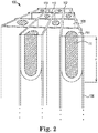
- FIG. 1 illustrates an exemplary honeycomb wall flow filter 100 according to exemplary embodiments.
- the general structure includes a body 101 made of intersecting porous ceramic walls 106 extending from a first end face 102 to a second end face 104.
- the intersecting porous ceramic walls 106 form channels extending axially from the first end face 102 to the second end face 104.
- Certain channels are designated as inlet channels 108 and certain other channels are designated as outlet channels 110.
- certain selected channels include plugs 112.
- the plugs are arranged at the ends of the channels and in some defined pattern, such as the checkerboard patterns shown.
- the inlet channels 108 are plugged at the outlet end face 104 and the outlet channels 110 are plugged at the inlet end face 102.
- each channel wall 14 for the filter can be for example from about 76 to about 762 ⁇ m (about 0.003 to about 0.030 inches).
- the cell density can be for example between about 15.5 and 139.5 cells per square cm (100 and 900 cells per square inch (cpsi)).
- the body 101 can include at least one of cordierite, mullite, alumina, silicon carbide, zirconia, corundum, corundum-mullite, spodumene, and aluminum titanate, but is not limited thereto.
- the body 101 is a honeycomb ceramic body to be used as a particulate filter with the operation of vehicle engines or other environmental applications.
- the network of channels is a honeycomb network.
- the channels can include a rectangular (e.g., square) cross-section, other polygonal shape having three or more sides, or a combination thereof, wherein the channels may also be of various cross-section size.
- the body 101 can include an outer cross-sectional periphery that is circular, oval, another curved shape, polygonal shape such as triangular, rectangular (e.g., square), or other polygonal shape.
- a portion of the channels 110 of a formed monolithic honeycomb 100 can be plugged at the inlet end 102 with a paste having the same or similar composition to that of the body 101.
- the plugging can be performed only at the ends of the channels 110 or spaced apart from the inlet end 102 of the channels 110 for fast light-off and form plugs 112 having a depth of about 5 to 20 mm, although this can vary.
- a portion of the channels 108 on the outlet end 104 but not corresponding to those on the inlet end 102 may also be plugged in a similar pattern. Therefore, each channel is plugged only at one end.
- the arrangement can have every other cell on a given face plugged as in a checkered pattern as shown in FIG. 1 .
- the inlet and outlet channels 108, 110 can be any desired shape. However, in the exemplified embodiment shown in FIG. 1 , the cell channels are square in cross-sectional shape.
- Catalyst can be added to the porous ceramic honeycomb body by washcoating, which deposits catalytic material in the porous walls of the honeycomb and sometimes on the channel surfaces. High temperatures occurring during soot burn-out can deteriorate the catalyst due to temperature aging. A high initial amount of active washcoat can be used to compensate and to comply with emissions regulations that may specify compliance after a required vehicle aging and therefore catalyst aging period. Also, washcoating generally adds to a filter's backpressure and the backpressure of the washcoated filter must not be too high to avoid a power or fuel consumption penalty. Washcoated filters, while catalytically active, have higher pressure drop compared to a bare filter and thus reduce power and efficiency of the engine.
- achieving low washcoated pressure drop may be challenging for diesel particulate filters (DPFs) with integrated selective catalytic reduction (SCR) catalytic functionality when the washcoat loading required to achieve emissions targets is high.
- DPFs diesel particulate filters
- SCR selective catalytic reduction
- the pressure drop of such integrated DPFs can be sensitive to small changes in washcoat loading.
- the porosity of the honeycomb material may be increased to enable high washcoat loadings at low backpressure. Trade-offs may be increased cost, reduced soot-mass limit, and decreased mechanical strength of the honeycomb body.
- Another strategy to address catalyst aging and the higher pressure drop is to use a larger filter volume, but this leads to increased space and material cost.
- a honeycomb material composed of the catalyst material may be used, leading to decreased soot mass limit, but with decreased thermo-mechanical durability and likely increased cost.
- NOx conversion of exhaust gas is initially focused at the inlet of a filter catalyzed with SCR coating since the inlet heats up more quickly than the rest of the filter.
- Low temperature and early heat up conditions have been the most difficult conditions to achieve good conversion.
- the presence of the plugs on the inlet face make the task more difficult as the additional mass of the plugs delays the thermal response of the inlet region. It was surprisingly discovered that making the plugs themselves reactive such that they participate in the conversion of the exhaust gas improved low temperature and early heat up conditions to achieve good conversion. It was further discovered that shifting the plug mass further down the filter channel improved low temperature and early heat up conditions to achieve good conversion.
- exemplary embodiments provide a filter with at least one of catalytically active and chemically active plugs.
- the at least one of catalytically active and chemically active plugs are referred to herein as active plugs and material that is at least one of catalytically active and chemically active is referred to herein as active material.
- the active plugs are more than simply inactive or non-active plugs (inert plugs) coated with an active material.
- inactive plugs in other words, a batch cement composition that forms each plug includes the active material.
- the active material is incorporated in and forms the structure of the active plugs.
- active material in an active body refers to active material incorporated in to form the structure of the active body.
- the structure of the body refers to, for example, ligaments between pores.
- an active body containing an active material refers to active material incorporated in to form the structure of the active body.
- active material on a body or on an active body, for example, plugs or walls refers to active material disposed on a surface including a surface in a pore of the body or active body, for example, as a result of washcoating or similar process.
- the active material in the active plugs can, for example, be a zeolite.
- the active material can be small pore zeolite such as copper-chabazite zeolite (CuCHA), present as catalyst for the selective catalytic reduction of NOx, Cu-exchanged zeolite, Fe-exchanged zeolite, a hydrocarbon-adsorbing zeolite, a high-surface-area material such as alumina, ceria, or zirconia with dispersed precious-metal such as Pt, Pd, or Rh, high surface area titania with vanadia, rhodium-titania, calcium carbonate, HC traps, high surface area material plus a noble metal, high surface area material, on board diagnosis oxygen storage material, ceria:zirconia solid solution material, ceria and zirconia multi-phase material, a three way catalyst (TWC), an alkali earth metal oxide such as potassium carbonate:cobalt oxide:lanthanum oxide, and the like,
- the active plugs can be a mixture of active and inactive materials, such as a mixture of zeolite, cordierite, and colloidal silica.
- a method of making an exhaust gas filter with copper zeolite plugs includes the plugging paste having a copper salt such as copper-acetate and a colloid silica binder.
- the active plugs may further be coated with an active material, for example, platinum, palladium, rhodium, zeolites, a high-surface-area material such as alumina, ceria, or zirconia with dispersed precious-metal such as Pt, Pd, or Rh, high surface area titania with vanadia, etc., and combinations thereof.
- the active plugs are made from active batch cement compositions.
- the compositions can include active and inactive materials.
- the inactive materials can include an inert refractory filler having a particle size distribution, an organic binder, an inorganic binder, and a liquid vehicle.
- the active materials can include an active filler such as a zeolite, copper-exchanged zeolite, iron-exchanged zeolite, copper-chabazite, a hydrocarbon-adsorbing zeolite, a high-surface-area material such as alumina, ceria, or zirconia with dispersed precious-metal such as Pt or Pd, high surface area titania with vanadia, and the like, or mixtures thereof.
- an active filler such as a zeolite, copper-exchanged zeolite, iron-exchanged zeolite, copper-chabazite, a hydrocarbon-adsorbing zeolite, a high-surface-area material such as alumina, ceria, or zirconia with dispersed precious-metal such as Pt or Pd, high surface area titania with vanadia, and the like, or mixtures thereof.
- the refractory filler, the particle size distribution of the refractory filler, the organic binder, and the inorganic binder are selected such that, when the composition including the active material is applied to plug a plurality of channels of the honeycomb body, a plurality of plugs formed therefrom have the desired properties, such as plug depth variability, plug depth, push-out strength, catalytic activity, chemical activity, coefficient of thermal expansion (CTE), porosity, permeability, etc.
- the inert refractory filler can include at least one inorganic powder.
- the inorganic powder may, for example, include a ceramic, i.e., pre-reacted or ceramed, refractory powder.
- the powders can be refractory glass powders, or glass-ceramic powders.
- the inorganic powder batch mixture can comprise any combination of two or more of the aforementioned refractory powders.
- Exemplary refractory powders may include cordierite, mullite, aluminum titanate, silicon carbide, silicon nitride, calcium aluminate, beta-eucryptite, and beta-spodumene.
- compositions further comprise a binder component comprised of an inorganic binder.
- the inorganic binder is a gelled inorganic binder such as gelled colloidal silica.
- Other embodiments of an inorganic binder could include a non-gelled colloidal silica, a powdered silica, or a low-temperature glass.
- the incorporation of a gelled inorganic binder may minimize or even prevent the migration of the inorganic binder particles into microcracks of a honeycomb body on which the composition is applied.
- gelled inorganic binder refers to a colloidal dispersion of solid inorganic particles in which the solid inorganic particles form an interconnected network or matrix in combination with a continuous fluid phase, resulting in a viscous semi-rigid material. Further, it should be understood that there can be relative levels or degrees of gelation.
- a gelled inorganic binder as used herein comprises an interconnected network of the dispersed inorganic particles that is sufficient to prevent at least a portion of the inorganic binder particles from migrating into microcracks of a honeycomb structure upon which the composition containing the gelled inorganic binder has been applied.
- the non-gelled colloidal silica can subsequently be gelled by the addition of one or more gelling agents to the composition.
- colloidal silica may be gelled by increasing the ion concentration of the composition.
- colloidal silica can be gelled by altering the pH of the composition.
- Still further embodiments can comprise both increasing the ion concentration and altering the pH of the composition.
- the gelling agent can be used in any amount effective to provide a gelled inorganic binder as described herein.
- Exemplary colloidal silicas can include the Ludox® HS, AS, SK, PW50, and PZ50 available from W.R. Grace & Company, and can be gelled by increasing the ion concentration by addition of salts and/or by changing the pH.
- Ludox® PW50EC a polydisperse colloidal silica
- Ludox® PW50EC has a much broader particle size range than the small silica particle size of Ludox® HS-40.
- Ludox® PW50EC has a particle size range D 50 of approximately 10-100 nm particle size distribution (PSD) as compared to about 12 nm D 50 in Ludox® HS-40.
- PSD particle size distribution
- the larger particles of Ludox® PW50EC do not migrate as easily leaving them dispersed and in the bulk cement mixture.
- the smallest of the particles in the Ludox® PW50EC are still able to migrate and migrate into the substrate.
- Exemplary compositions disclosed herein may further comprise an organic binder.
- the addition of the organic binder component can further contribute to the cohesion and plasticity of the composition prior to firing. This improved cohesion and plasticity can, for example, improve the ability to shape the composition. This can be advantageous when utilizing the composition to form skin coatings or when plugging selected portions (such as the ends) of a honeycomb structural body.
- Exemplary organic binders include cellulose materials.
- Exemplary cellulose materials include cellulose ether binders such as methylcellulose, hydroxypropyl methylcellulose, methylcellulose derivatives, and/or any combinations thereof.
- cellulose materials include combination of methylcellulose and hydroxypropyl methylcellulose.
- the organic binder can be present in the composition as a super addition in an amount in the range of from 0.1 weight percent to 5.0 weight percent of the inorganic powder batch composition, or even in an amount in the range of from 0.5 weight percent to 2.0 weight percent of the inorganic powder batch composition.
- An exemplary liquid vehicle for providing a flowable or paste-like consistency to the disclosed compositions is water, although other liquid vehicles can be used.
- the amount of the liquid vehicle component can vary in order to provide optimum handling properties and compatibility with the other components in the batch mixture.
- the liquid vehicle content is present as a super addition in an amount in the range of from 15% to 60% by weight of the inorganic powder batch composition, or even according to some embodiments can be in the range of from 20% to 50% by weight of the inorganic powder batch mixture. Minimization of liquid components in the compositions can also lead to further reductions in the drying shrinkage of the compositions during the drying process.
- Exemplary compositions disclosed herein can optionally comprise one or more processing aids such as a plasticizer, lubricant, surfactant, sintering aid, rheology modifier, thixotropic agent, dispersing agents, or pore former.
- a plasticizer for use in preparing the plugging composition is glycerine.
- An exemplary lubricant can be a hydrocarbon oil or tall oil.
- Exemplary commercially available lubricants include Liga GS, available from Peter Greven Fett-Chemie and Durasyn® 162 hydrocarbon oil available from Innovene.
- a commercially available thixotropic agent is Benaqua 1000 available from Rheox, Inc.
- a pore former may also be optionally used to produce a desired porosity of the resulting ceramed composition.
- exemplary and non-limiting pore formers can include graphite, starch, polyethylene beads, and/or flour.
- Exemplary dispersing agents that can be used include the NuoSperse® 2000 from Elementis and ZetaSperse® 1200, available from Air Products and Chemicals, Inc.
- the inactive and active components as described above can be mixed together, the inorganic powder batch mixture as described above can be mixed together with the organic binder, followed by the incorporation of the liquid vehicle and inorganic binder components.
- the inorganic binder can be non-gelled or gelled either before or after having been introduced into the composition. If the inorganic binder is to be gelled prior to addition to the composition, the one or more gelling agents can be added to the inorganic binder, such as for example, a colloidal silica. Alternatively, if the inorganic binder is to be gelled after addition to the powder composition, the one or more gelling agents can be introduced directly into the composition.
- any optional processing aids can also be introduced into the composition during or after the liquid addition.
- a rheology modifier such as polyvinyl alcohol can first be mixed with the inorganic binder and, optionally the refractory powder. Once the desired components are combined, the composition can be thoroughly mixed to provide a flowable paste-like consistency to the composition.
- the mixing as described above can be done using a Littleford mixer or a Turbula mixer.
- the compositions disclosed herein can be applied to a honeycomb body or structure defining a plurality of cell channels bounded by cell channel walls as described above.
- the compositions disclosed herein can be used as plugging material to plug selected channels of a honeycomb body in order to form a wall flow filter.
- at least a portion of the plurality of cell channels can comprise active plugs, wherein the active plugs are formed from a composition as disclosed herein.
- a first portion of the plurality of cell channels can comprise an active plug sealed to the respective channel walls at or near the upstream inlet end to form outlet cell channels.
- a second portion of the plurality of cell channels can also comprise an active plug sealed to the respective channel walls at or near the downstream outlet end to form inlet cell channels.
- Other configurations having only one end plugged, as well as partially plugged configurations (having some unplugged channels) are also contemplated.
- the composition can be optionally dried and/or fired.
- the optional drying step can comprise first heating the composition at a temperature and for a period of time sufficient to at least substantially remove any liquid vehicle that may be present in the composition.
- at least substantially removing any liquid vehicle includes the removal of at least 90%, at least 95%, at least 98%, at least 99%, or even at least 99.9% of the liquid vehicle present in the composition prior to firing.
- Exemplary and non-limiting drying conditions suitable for removing the liquid vehicle include heating the composition at a temperature of at least 50° C, at least 60° C, at least 70° C, at least 80° C, at least 90° C, at least 100° C, at least 110° C, at least 120° C, at least 130° C, at least 140° C, or even at least 150° C.
- the conditions effective to at least substantially remove the liquid vehicle comprise heating the composition at a temperature in the range of from 60° C to 120° C.
- the heating can be provided by any conventionally known method, including for example, hot air drying, IR, RF and/or microwave drying.
- the optional firing step can include conditions suitable for converting the composition to a primary crystalline phase ceramic composition include heating the honeycomb with applied composition to a peak temperature of greater than 800° C, 900° C, and even greater than 1000° C. A ramp rate of about 120° C/hr during heating may be used, followed by a hold at the peak temperature for a temperature of about 3 hours, followed by cooling at about 240° C/hr.
- compositions disclosed herein can include those that set at a temperature of less than 200° C, such as a temperature of less than 100° C, and further such as a temperature of less than 50° C, including compositions that can be used in plugging processes employing "cold set" plugs.
- cold set plugging only drying of the plugging mixture is required to form a seal between the plugs and the channel walls of the honeycombs.
- heating of the plugged honeycombs to temperatures in the 35-110° C range can be useful to accelerate drying.
- final plug consolidation including the removal of residual temporary binder bi-products and strengthening of the seals, can occur in the course of subsequent processing steps (e.g., in the course of catalyzation or canning) or during first use (e.g., in an exhaust system).
- active plugs at the first end face of a porous ceramic honeycomb body can have a first active component and seal a portion of the outlet channels, including for example, all of the outlet channels or only outlet channels in a certain region such as a center region, a periphery region, an intermediate region, or a plurality of regions of the first end face.
- the first active component can include a plurality of active components and the active plugs in a certain region can have an active component different than active plugs in another region of the first end face.
- another portion of the outlet channels that are not sealed by active plugs having the first active component can be open as described above, sealed by inert plugs, or a combination thereof.
- the walls of the porous ceramic honeycomb body can be inert, have a second active component disposed thereon, have a structure containing another active component, or any combination thereof.
- the second active component is not the same as the first active component.
- the first active component includes a plurality of active components
- the second active component may be the same as at least one, but not all of the plurality of first active components.
- the first active component may merely be a different concentration than the second active component, have a different particle size distribution, a different microstructure, and the like, or any combination thereof.
- the second active component includes a plurality of active components, at least one of the plurality of second active components, but not all, may be the same as the first active component.
- active plugs at the second end face of the porous ceramic honeycomb body can have the first active component and seal a portion of the inlet channels, including for example, all of the inlet channels or only inlet channels in a certain region such as a center region, a periphery region, an intermediate region, or a plurality of regions of the second end face.
- the first active component can include a plurality of active components and the active plugs in a certain region can have an active component different than active plugs in another region of the second end face.
- another portion of the inlet channels that are not sealed by active plugs having the first active component can be sealed by inert plugs.
- the inlet channels can be sealed at the second end face with active plugs having the first active component, sealed at the second end face with inert plugs, or any combination thereof.
- active plugs at the first end face can have a different first active component than active plugs at the second end face.
- the first active component can include a first temperature active component active in a first temperature range and a second temperature active component active in a second temperature range.
- the first and second temperature ranges may overlap, but the first temperature range can have a lower boundary less than the second temperature range lower boundary and the second temperature range can have an upper boundary greater than the first temperature range upper boundary.
- the first temperature active component can be disposed in active plugs at an inlet face and the second temperature active component can be disposed in active plugs at an outlet face.
- the first temperature active component can be disposed in active plugs in a central region of an inlet face and the second temperature active component can be disposed in active plugs in a peripheral region of the inlet face.
- the first temperature active component can be disposed in active plugs in a central region of an outlet face and the second temperature active component can be disposed in active plugs in a peripheral region of the outlet face.
- the first active component can include a catalytically active component at the first end face effective to convert at least 40% of NOx in an exhaust gas and a chemically active component at the second end face effective to convert HC in the exhaust gas.
- the catalytically active component can be disposed in active plugs in a central region of an inlet face and the chemically active component can be disposed in active plugs in a peripheral region of the inlet face.
- the outlet channels can be open, sealed at the first end face with active plugs having the first active component, sealed at the first end face with active plugs having another active component, sealed at the first end face with inert plugs, or any combination thereof.
- the active plugs comprise between 10 wt% and 90 wt% of the first active component.
- the active plugs comprise between 20 wt% and 80 wt% of the first active component.
- the active plugs comprise between 30 wt% and 70 wt% of the first active component, or even between 40 wt% and 60 wt% of the first active component.
- the active plugs including different first active components may merely include different amounts of the first active component.
- active plugs in a center region of an inlet face may include 60 wt% to 80 wt% of the first active component and active plugs in a peripheral region of an inlet face may include 20 wt% to 40 wt% of the first active component.
- the active plugs in at least one of a portion of the outlet channels and a portion of the inlet channels can be axially spaced apart from the respective end face. That is, for example, when at least a portion of the outlet channels are plugged at the inlet face, the plugs, including active plugs, may be offset from the inlet face. This can provide a reduction in thermal mass near the inlet region of a filter by moving the plugs downstream. This can provide early light-off advantages, overall higher conversion, and elimination of additional stacked light-off filter upstream of the filter having offset plugs according to these exemplary embodiments.
- the active plugs in at least one of a portion of the outlet channels and a portion of the inlet channels can each include a first layer disposed in contact with the intersecting walls and a second layer disposed on the first layer inward toward an axial center of each channel from the intersecting walls, where at least one of the first layer and the second layer includes the first active component.
- the plugs 112, including active plugs may have a composite structure 114, 116.
- This can provide control over plug properties that vary in a direction perpendicular to the axial channel direction.
- the first active component in the composite active plug may be in a second layer 116 having a coefficient of thermal expansion (CTE) different than the CTE of the honeycomb body walls 106.
- CTE coefficient of thermal expansion
- the first layer 114 can have a CTE intermediate between the CTE of the second layer 116 and the CTE of the honeycomb body walls 106 according to these exemplary.
- the first active component comprises a plurality of active components
- the first layer 114 and the second layer 116 according to these exemplary embodiments may include different active components.
- a method of making the active plugs in at least one of a portion of the outlet channels and a portion of the inlet channels having the composite layered structure 114, 116 is provided.
- a first layer patty is disposed on a second layer patty where the second layer patty is disposed on a support.
- the support is pressed toward a masked porous ceramic honeycomb body in an axial direction a predetermined distance to inject the first layer 114 and the second layer 116 in open channels of an end face to form plugs to seal the channels at the end face.
- the plugs include the first layer 114 disposed on the walls 106 of respective channels, and a second layer 116 disposed inward toward an axial center of each respective channel on the first layer. It was surprisingly discovered that the first layer patty disposed in a sheet perpendicular to the honeycomb body axial channel direction having the second layer patty disposed thereon forms a first layer of the composite plug on the honeycomb body walls perpendicular to the starting sheet with the second layer patty forming the second layer of the composite plug on the first layer also in a direction perpendicular to the starting position of the first layer patty and second layer patty to seal the honeycomb body channels.
- additional layers of the composite plugs can be formed by providing additional layer patties.
- a method of making the active plugs in at least one of a portion of the outlet channels and a portion of the inlet channels axially spaced apart from the respective end face is provided.
- the method can include masking an end face and pressing the plugging cement composition, for example, including the first active component, into the masked end face filling the open channels with the plugging cement composition.
- a patty comprised of an organic material, such as wax can be pressed into the masked end face to push the plugging cement composition further along the channels in the axial direction to offset the plugging cement composition from the end face.
- a heat treatment or chemical treatment can be used to burn out or remove the organic material.
- a heat treatment may simultaneously cure the plugging cement composition forming plugs bonded to the channel walls.
- steps 1 through 4 all powders were added to the mixing bowl and dry mix was performed for five minutes.
- Step 5 included measuring Ludox® HS-40.
- Step 6 included measuring TEA and water into separate containers, adding the water to the TEA and stirring TEA solution for one minute.
- Step 7 included adding the TEA solution to the Ludox® HS-40 and stirring for one minute.
- Steps 8 and 9 included adding all pre-mixed liquids and coloring to bowl when dry mixing was completed.
- Step 10 included performing wet mix for two minutes with NO vacuum, disperser @ 2,200 rpm and planetary @35 rpm.
- Step 11 included scraping batch from mixer beaters and around the inside of the bowl when wet mix was completed.
- Step 12 included performing final wet mix for eight minutes with vacuum of 38.1 cm (15 inches) of Hg, disperser @ 2,200 rpm and planetary @35 rpm.
- E1 and E2 compositions were mixed two times on channel 17 in Mazurestar® mixer. All samples were calcined at 650°C for 2hrs. The plug materials were also calcined separately to test the NO conversion as a powder ( FIG. 3 ).
- FIG. 3 is a graphical plot of data showing NO conversion of a comparative sample of copper-chabazite zeolite powder compared to powder according to an exemplary embodiment of the disclosed plug material showing that the catalytic activity is improved. That is, FIG. 3 shows that the active material is still active after making into a plug batch cement composition. FIG. 3 shows the catalytic activity for compositions, that is, not formed into plugs in honeycomb body channels. Surprisingly, the catalytically active copper-chabazite zeolite and colloidal silica made into the plug composition was even more catalytically active than the copper-chabazite zeolite alone.
- FIG. 4 shows steady state NOx conversion for three 5.08 cm x 15.24 cm (2"x6") AT filters.
- the absolute weight of zeolite, the normalized weight in g/L, and the plug depths "PD" are similar for the control and the active plugs.
- One of the AT filters has standard, catalytically non-active plugs and the conversion is close to zero.
- the other two AT filters have active plugs and the activity boost from the active plugs is clearly seen.
- FIG. 4 is a graphical plot of data showing the results of NO conversion efficiency for exemplary examples E1 and E2 and comparative example C1 with inactive plugs. The results for the powder sample according to the exemplary embodiment shown in FIG. 3 are also shown. FIG. 4 shows that the NO conversion for the comparative example C1 with the inactive plugs was close to zero, whereas the catalytic activity for the parts plugged with the exemplary examples E1 and E2 active plug composition showed significant NO conversion.
- a flow of exhaust gas through a pair of channels representing an inlet and outlet channel separated by a permeable membrane was modeled. Zeolite plugs were applied to the inlet and outlet face of alternate channels in the model. The modeling provided a determination of where and how much conversion of NO was occurring at different temperatures and for different washcoating strategies.
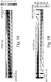
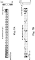
- FIGS. 5A and 5B are plots of modeling results of steady state flow velocity through two channels at 300°C with an inlet face active plug on the lower channel and an outlet face active plug on the upper channel according to these exemplary embodiments. Each channel is symmetric such that only half of the vertical extent of the channel is shown.
- FIGS. 6A and 6B are a close-up of the inlet region of the modeling results of FIGS. 5A and 5B showing the local reaction rate in the wall and the inlet face active plug at steady state at 300°C. Some NO conversion is occurring in the wall, but most of it is occurring in the inlet face active plug.
- FIGS. 7A and 7B are plots of modeling results showing distribution of NO in the channels at 300°C showing a rapid depletion of NO in the inlet face active plug, a gradual decrease as more NO reacts in the walls down the length of the part, and a final reduction in NO concentration in the outlet face active plug.
- FIG. 8 provides a graphical plot of data from simulated (squares) and experimental (triangles) NO conversion at constant temperature for two Cu-zeolite plugged filters according to exemplary embodiments.
- the calibrated model determined how varying the filter design altered the performance.
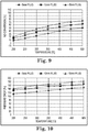
- FIG. 9 the impact of changing the length of the plugs on NO conversion is shown. As the plug length is increased, NO conversion increases for each temperature studied.
- FIG. 9 provides a graphical plot of calibrated modeled data showing NO conversion as a function of temperature for varying plug lengths according to exemplary embodiments. This increase in conversion at higher plug length comes at the cost of an increase in the pressure drop since the longer plugs leave less wall area for the exhaust gas to flow through between the inlet and outlet channels.
- FIG. 10 provides a graphical plot of calibrated modeled data showing pressure drop across the filter for varying plug lengths according to exemplary embodiments.
- FIG. 10 shows that the pressure drop increases by about 30 Pa as the active plug length is increased from 5 to 15 mm.
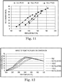
- the tradeoff between pressure drop and conversion can be seen in FIG. 11 .
- FIG. 11 provides a graphical plot of calibrated modeled data showing balance between improved NO conversion and increased back pressure for various active plug lengths according to exemplary embodiments. If the increase in pressure drop is acceptable, the longer active plug length provides the best conversion. When a maximum allowable pressure drop is specified for a certain application, the active plug length can be adjusted to meet the specified pressure drop while providing optimal conversion.
- FIG. 12 provides a graphical plot of calibrated modeled data showing impact of active plugs on washcoated filter according to exemplary embodiments. The presence of active plugs actually improved the conversion of an additionally washcoated filter. FIG. 12 shows that for all three levels of washcoat loading, adding Cu zeolite material to the plug further improved the conversion performance. Here, the improvement is evident in the 200 to 400°C temperature range.
- an exhaust gas filter with catalytically active plugs can have reduced emissions, lower pressure drop, lower cost, faster light off, and/or smaller size than a filter having non-active plugs.
- the catalytic activity contributed from active plugs can lead directly to a decrease in the washcoat loading needed to achieve emissions targets, with advantages in pressure drop and fast light off.
- exemplary embodiments of the reactive plugs provide improved NOx conversion, especially at low temperatures (e.g., up to 400°C), which is a significant challenge in SCR technology.
- Advantages of exemplary embodiments include using longer zeolite plugs to provide progressively higher NOx conversion with only slightly higher pressure drop. This trend continues up to at least 15 mm active plugs. Compared to a filter washcoated with zeolite, adding zeolite containing plugs further improves the conversion efficiency at temperatures from 200 to 400°C. Advantages of exemplary embodiments include active plugs for hydrocarbon (HC) traps. Advantages include improved utilization of the space occupied by the filter. In contrast, non-active plugs are inert and represent dead space.
- HC hydrocarbon
- the method of making plugs according to exemplary embodiments can result in improved catalytic activity and reduced interaction of colloidal material with microcracks in the honeycomb body.
Landscapes
- Chemical & Material Sciences (AREA)
- Engineering & Computer Science (AREA)
- Ceramic Engineering (AREA)
- Materials Engineering (AREA)
- Organic Chemistry (AREA)
- Structural Engineering (AREA)
- Chemical Kinetics & Catalysis (AREA)
- Crystallography & Structural Chemistry (AREA)
- Environmental & Geological Engineering (AREA)
- Analytical Chemistry (AREA)
- Oil, Petroleum & Natural Gas (AREA)
- General Chemical & Material Sciences (AREA)
- Health & Medical Sciences (AREA)
- Biomedical Technology (AREA)
- Manufacturing & Machinery (AREA)
- Mechanical Engineering (AREA)
- Inorganic Chemistry (AREA)
- Combustion & Propulsion (AREA)
- Filtering Materials (AREA)
- Catalysts (AREA)
- Exhaust Gas Treatment By Means Of Catalyst (AREA)
- Exhaust Gas After Treatment (AREA)
- Processes For Solid Components From Exhaust (AREA)
- Physics & Mathematics (AREA)
- Geometry (AREA)
- Civil Engineering (AREA)
Applications Claiming Priority (2)
| Application Number | Priority Date | Filing Date | Title |
|---|---|---|---|
| US201462045217P | 2014-09-03 | 2014-09-03 | |
| PCT/US2015/048010 WO2016036780A1 (en) | 2014-09-03 | 2015-09-02 | Exhaust filter with active plugs |
Publications (2)
| Publication Number | Publication Date |
|---|---|
| EP3189020A1 EP3189020A1 (en) | 2017-07-12 |
| EP3189020B1 true EP3189020B1 (en) | 2020-12-23 |
Family
ID=54148616
Family Applications (1)
| Application Number | Title | Priority Date | Filing Date |
|---|---|---|---|
| EP15766681.9A Active EP3189020B1 (en) | 2014-09-03 | 2015-09-02 | Exhaust filter with active plugs |
Country Status (7)
| Country | Link |
|---|---|
| US (1) | US10898856B2 (enExample) |
| EP (1) | EP3189020B1 (enExample) |
| JP (1) | JP6789927B2 (enExample) |
| CN (1) | CN107073377B (enExample) |
| MX (1) | MX2017002813A (enExample) |
| WO (1) | WO2016036780A1 (enExample) |
| ZA (1) | ZA201701580B (enExample) |
Cited By (1)
| Publication number | Priority date | Publication date | Assignee | Title |
|---|---|---|---|---|
| WO2025106325A1 (en) * | 2023-11-16 | 2025-05-22 | Corning Incorporated | Carbon capture article with zeolite and silicone resin, method of making same, and method of using same |
Families Citing this family (9)
| Publication number | Priority date | Publication date | Assignee | Title |
|---|---|---|---|---|
| GB201517578D0 (en) * | 2015-10-06 | 2015-11-18 | Johnson Matthey Plc | Passive nox adsorber |
| US10105691B2 (en) * | 2016-03-31 | 2018-10-23 | Ford Global Technologies, Llc | Multiple zeolite hydrocarbon traps |
| JP2018103132A (ja) * | 2016-12-27 | 2018-07-05 | 株式会社キャタラー | 排ガス浄化用触媒 |
| CN108854323B (zh) * | 2018-07-06 | 2020-09-08 | 江西博鑫精陶环保科技有限公司 | 一种蜂窝壁流式高温尘硝一体净化器的制备方法 |
| US11174774B2 (en) * | 2018-10-27 | 2021-11-16 | Imagine Tf, Llc | Structures for catalytic converters |
| JP2021023853A (ja) | 2019-08-01 | 2021-02-22 | トヨタ自動車株式会社 | 排ガス浄化装置及び排ガス浄化システム並びに排ガス浄化装置の製造方法 |
| WO2021201018A1 (ja) * | 2020-03-31 | 2021-10-07 | 東ソー株式会社 | 炭化水素吸着剤及び炭化水素の吸着方法 |
| JP7443200B2 (ja) * | 2020-09-03 | 2024-03-05 | 日本碍子株式会社 | 多孔質セラミックス構造体 |
| CN118925435B (zh) * | 2024-08-27 | 2025-10-31 | 大连理工大学 | 一种碳捕集的蜂窝式填充床 |
Family Cites Families (24)
| Publication number | Priority date | Publication date | Assignee | Title |
|---|---|---|---|---|
| DE69629979T2 (de) * | 1995-06-02 | 2004-07-29 | Corning Inc. | Vorrichtung zur Entfernung von Kontaminationen aus Fluidströmen |
| WO2002085482A2 (en) | 2001-04-23 | 2002-10-31 | Dow Global Technologies Inc. | Method of making wall-flow monolith filter |
| PL366538A1 (pl) | 2001-04-23 | 2005-02-07 | Dow Global Technologies Inc. | Sposób wytwarzania monolitycznego filtra z przepływem ściennym |
| US7107763B2 (en) * | 2002-03-29 | 2006-09-19 | Hitachi Metals, Ltd. | Ceramic honeycomb filter and exhaust gas-cleaning method |
| JP3867976B2 (ja) * | 2002-03-29 | 2007-01-17 | 日立金属株式会社 | セラミックハニカムフィルタ及び排気ガス浄化方法 |
| DE10250050A1 (de) | 2002-10-25 | 2004-05-06 | Purem Abgassysteme Gmbh & Co. Kg | Abgasnachbehandlungssystem, insbesondere für einen Dieselmotor |
| JP4394408B2 (ja) | 2002-11-08 | 2010-01-06 | 日本碍子株式会社 | ハニカム構造体のセルを封止する方法及びハニカム封止体の製造方法 |
| JP4767491B2 (ja) * | 2003-12-11 | 2011-09-07 | 日本碍子株式会社 | ハニカム構造体 |
| JP2005270755A (ja) | 2004-03-24 | 2005-10-06 | Ngk Insulators Ltd | ハニカム構造体及びその製造方法 |
| JP2009519814A (ja) | 2005-12-16 | 2009-05-21 | コーニング インコーポレイテッド | 圧力降下の低い被覆ディーゼル排ガスフィルタ |
| JP5223340B2 (ja) | 2006-01-27 | 2013-06-26 | 日立金属株式会社 | セラミックハニカムフィルタの製造方法 |
| WO2007102561A1 (ja) * | 2006-03-07 | 2007-09-13 | Ngk Insulators, Ltd. | セラミック構造体及びその製造方法 |
| WO2008126328A1 (ja) | 2007-03-30 | 2008-10-23 | Ibiden Co., Ltd. | ハニカムフィルタ |
| CN101827654B (zh) | 2007-08-13 | 2013-11-06 | Pq公司 | 含铁铝硅酸盐沸石及其制备和使用方法 |
| CN101952224B (zh) | 2007-11-30 | 2013-08-21 | 康宁股份有限公司 | 沸石基蜂窝体 |
| KR101028548B1 (ko) | 2008-09-05 | 2011-04-11 | 기아자동차주식회사 | 배기가스 정화장치 |
| JP5219741B2 (ja) | 2008-10-31 | 2013-06-26 | 日本碍子株式会社 | ハニカム構造体、並びにハニカム触媒体 |
| JP5219742B2 (ja) | 2008-10-31 | 2013-06-26 | 日本碍子株式会社 | ハニカム構造体及びハニカム触媒体 |
| JP2011206636A (ja) | 2010-03-29 | 2011-10-20 | Kyocera Corp | ハニカム構造体およびこれを用いた排気ガス処理装置 |
| WO2011135683A1 (ja) * | 2010-04-27 | 2011-11-03 | イビデン株式会社 | ハニカム構造体の製造方法及びハニカム構造体 |
| US8609032B2 (en) * | 2010-11-29 | 2013-12-17 | Corning Incorporated | Porous ceramic honeycomb articles and methods for making the same |
| RU2597090C2 (ru) | 2011-05-31 | 2016-09-10 | Джонсон Мэтти Паблик Лимитед Компани | Каталитический фильтр с двойной функцией |
| US9359262B2 (en) * | 2012-08-30 | 2016-06-07 | Corning Incorporated | Compositions and methods for plugging honeycomb bodies with reduced plug depth variability |
| US8999484B2 (en) | 2012-08-30 | 2015-04-07 | Corning Incorporated | Compositions and methods for plugging honeycomb bodies with reduced plug depth variability |
-
2015
- 2015-09-02 CN CN201580059542.9A patent/CN107073377B/zh active Active
- 2015-09-02 EP EP15766681.9A patent/EP3189020B1/en active Active
- 2015-09-02 JP JP2017512802A patent/JP6789927B2/ja active Active
- 2015-09-02 US US15/508,812 patent/US10898856B2/en not_active Expired - Fee Related
- 2015-09-02 MX MX2017002813A patent/MX2017002813A/es unknown
- 2015-09-02 WO PCT/US2015/048010 patent/WO2016036780A1/en not_active Ceased
-
2017
- 2017-03-03 ZA ZA2017/01580A patent/ZA201701580B/en unknown
Non-Patent Citations (1)
| Title |
|---|
| None * |
Cited By (1)
| Publication number | Priority date | Publication date | Assignee | Title |
|---|---|---|---|---|
| WO2025106325A1 (en) * | 2023-11-16 | 2025-05-22 | Corning Incorporated | Carbon capture article with zeolite and silicone resin, method of making same, and method of using same |
Also Published As
| Publication number | Publication date |
|---|---|
| WO2016036780A1 (en) | 2016-03-10 |
| JP6789927B2 (ja) | 2020-11-25 |
| EP3189020A1 (en) | 2017-07-12 |
| MX2017002813A (es) | 2018-01-12 |
| JP2017527437A (ja) | 2017-09-21 |
| CN107073377B (zh) | 2021-02-26 |
| ZA201701580B (en) | 2022-05-25 |
| CN107073377A (zh) | 2017-08-18 |
| US20170282124A1 (en) | 2017-10-05 |
| US10898856B2 (en) | 2021-01-26 |
Similar Documents
| Publication | Publication Date | Title |
|---|---|---|
| EP3189020B1 (en) | Exhaust filter with active plugs | |
| EP1741686B1 (en) | Honeycomb structure and method for producing same | |
| EP1982767B1 (en) | Honeycomb segment, honeycomb structure and process for producing the same | |
| JP6998871B2 (ja) | ハニカム構造体及び該ハニカム構造体の製造方法 | |
| EP2937143B1 (en) | Ceramic honeycomb structure and method for producing same | |
| EP2177253B1 (en) | Honeycomb structure | |
| EP2108439A1 (en) | Catalytic diesel particulate filter and manufacturing method thereof | |
| CN111747751B (zh) | 陶瓷多孔体及其制造方法、以及集尘用过滤器 | |
| JP5096978B2 (ja) | ハニカム触媒体 | |
| JP2011194312A (ja) | ハニカム構造体 | |
| JP6949019B2 (ja) | ハニカム構造体及び該ハニカム構造体の製造方法 | |
| EP2174698A1 (en) | Honeycomb Structure | |
| JP5869407B2 (ja) | 複合ハニカム構造体 | |
| US12305551B2 (en) | Filter and method for manufacturing same | |
| US11459924B2 (en) | Honeycomb body having layered plugs and method of making the same | |
| US20080170973A1 (en) | Catalytic Filter For Filtering a Gas Comprising a Coating and/or a Joint With Controlled Porosity | |
| JP2010029848A (ja) | ハニカム構造体 | |
| JP6581917B2 (ja) | ハニカム構造体 |
Legal Events
| Date | Code | Title | Description |
|---|---|---|---|
| STAA | Information on the status of an ep patent application or granted ep patent |
Free format text: STATUS: THE INTERNATIONAL PUBLICATION HAS BEEN MADE |
|
| PUAI | Public reference made under article 153(3) epc to a published international application that has entered the european phase |
Free format text: ORIGINAL CODE: 0009012 |
|
| STAA | Information on the status of an ep patent application or granted ep patent |
Free format text: STATUS: REQUEST FOR EXAMINATION WAS MADE |
|
| 17P | Request for examination filed |
Effective date: 20170328 |
|
| AK | Designated contracting states |
Kind code of ref document: A1 Designated state(s): AL AT BE BG CH CY CZ DE DK EE ES FI FR GB GR HR HU IE IS IT LI LT LU LV MC MK MT NL NO PL PT RO RS SE SI SK SM TR |
|
| AX | Request for extension of the european patent |
Extension state: BA ME |
|
| DAV | Request for validation of the european patent (deleted) | ||
| DAX | Request for extension of the european patent (deleted) | ||
| STAA | Information on the status of an ep patent application or granted ep patent |
Free format text: STATUS: EXAMINATION IS IN PROGRESS |
|
| 17Q | First examination report despatched |
Effective date: 20190603 |
|
| GRAP | Despatch of communication of intention to grant a patent |
Free format text: ORIGINAL CODE: EPIDOSNIGR1 |
|
| STAA | Information on the status of an ep patent application or granted ep patent |
Free format text: STATUS: GRANT OF PATENT IS INTENDED |
|
| INTG | Intention to grant announced |
Effective date: 20200421 |
|
| GRAJ | Information related to disapproval of communication of intention to grant by the applicant or resumption of examination proceedings by the epo deleted |
Free format text: ORIGINAL CODE: EPIDOSDIGR1 |
|
| STAA | Information on the status of an ep patent application or granted ep patent |
Free format text: STATUS: EXAMINATION IS IN PROGRESS |
|
| GRAS | Grant fee paid |
Free format text: ORIGINAL CODE: EPIDOSNIGR3 |
|
| STAA | Information on the status of an ep patent application or granted ep patent |
Free format text: STATUS: GRANT OF PATENT IS INTENDED |
|
| GRAP | Despatch of communication of intention to grant a patent |
Free format text: ORIGINAL CODE: EPIDOSNIGR1 |
|
| INTC | Intention to grant announced (deleted) | ||
| INTG | Intention to grant announced |
Effective date: 20200921 |
|
| GRAA | (expected) grant |
Free format text: ORIGINAL CODE: 0009210 |
|
| STAA | Information on the status of an ep patent application or granted ep patent |
Free format text: STATUS: THE PATENT HAS BEEN GRANTED |
|
| AK | Designated contracting states |
Kind code of ref document: B1 Designated state(s): AL AT BE BG CH CY CZ DE DK EE ES FI FR GB GR HR HU IE IS IT LI LT LU LV MC MK MT NL NO PL PT RO RS SE SI SK SM TR |
|
| REG | Reference to a national code |
Ref country code: GB Ref legal event code: FG4D |
|
| REG | Reference to a national code |
Ref country code: DE Ref legal event code: R096 Ref document number: 602015063841 Country of ref document: DE |
|
| REG | Reference to a national code |
Ref country code: AT Ref legal event code: REF Ref document number: 1347556 Country of ref document: AT Kind code of ref document: T Effective date: 20210115 |
|
| REG | Reference to a national code |
Ref country code: IE Ref legal event code: FG4D |
|
| PG25 | Lapsed in a contracting state [announced via postgrant information from national office to epo] |
Ref country code: NO Free format text: LAPSE BECAUSE OF FAILURE TO SUBMIT A TRANSLATION OF THE DESCRIPTION OR TO PAY THE FEE WITHIN THE PRESCRIBED TIME-LIMIT Effective date: 20210323 Ref country code: RS Free format text: LAPSE BECAUSE OF FAILURE TO SUBMIT A TRANSLATION OF THE DESCRIPTION OR TO PAY THE FEE WITHIN THE PRESCRIBED TIME-LIMIT Effective date: 20201223 Ref country code: FI Free format text: LAPSE BECAUSE OF FAILURE TO SUBMIT A TRANSLATION OF THE DESCRIPTION OR TO PAY THE FEE WITHIN THE PRESCRIBED TIME-LIMIT Effective date: 20201223 Ref country code: GR Free format text: LAPSE BECAUSE OF FAILURE TO SUBMIT A TRANSLATION OF THE DESCRIPTION OR TO PAY THE FEE WITHIN THE PRESCRIBED TIME-LIMIT Effective date: 20210324 |
|
| REG | Reference to a national code |
Ref country code: AT Ref legal event code: MK05 Ref document number: 1347556 Country of ref document: AT Kind code of ref document: T Effective date: 20201223 |
|
| REG | Reference to a national code |
Ref country code: NL Ref legal event code: MP Effective date: 20201223 |
|
| PG25 | Lapsed in a contracting state [announced via postgrant information from national office to epo] |
Ref country code: LV Free format text: LAPSE BECAUSE OF FAILURE TO SUBMIT A TRANSLATION OF THE DESCRIPTION OR TO PAY THE FEE WITHIN THE PRESCRIBED TIME-LIMIT Effective date: 20201223 Ref country code: SE Free format text: LAPSE BECAUSE OF FAILURE TO SUBMIT A TRANSLATION OF THE DESCRIPTION OR TO PAY THE FEE WITHIN THE PRESCRIBED TIME-LIMIT Effective date: 20201223 Ref country code: BG Free format text: LAPSE BECAUSE OF FAILURE TO SUBMIT A TRANSLATION OF THE DESCRIPTION OR TO PAY THE FEE WITHIN THE PRESCRIBED TIME-LIMIT Effective date: 20210323 |
|
| PG25 | Lapsed in a contracting state [announced via postgrant information from national office to epo] |
Ref country code: NL Free format text: LAPSE BECAUSE OF FAILURE TO SUBMIT A TRANSLATION OF THE DESCRIPTION OR TO PAY THE FEE WITHIN THE PRESCRIBED TIME-LIMIT Effective date: 20201223 Ref country code: HR Free format text: LAPSE BECAUSE OF FAILURE TO SUBMIT A TRANSLATION OF THE DESCRIPTION OR TO PAY THE FEE WITHIN THE PRESCRIBED TIME-LIMIT Effective date: 20201223 |
|
| REG | Reference to a national code |
Ref country code: LT Ref legal event code: MG9D |
|
| PG25 | Lapsed in a contracting state [announced via postgrant information from national office to epo] |
Ref country code: EE Free format text: LAPSE BECAUSE OF FAILURE TO SUBMIT A TRANSLATION OF THE DESCRIPTION OR TO PAY THE FEE WITHIN THE PRESCRIBED TIME-LIMIT Effective date: 20201223 Ref country code: CZ Free format text: LAPSE BECAUSE OF FAILURE TO SUBMIT A TRANSLATION OF THE DESCRIPTION OR TO PAY THE FEE WITHIN THE PRESCRIBED TIME-LIMIT Effective date: 20201223 Ref country code: SM Free format text: LAPSE BECAUSE OF FAILURE TO SUBMIT A TRANSLATION OF THE DESCRIPTION OR TO PAY THE FEE WITHIN THE PRESCRIBED TIME-LIMIT Effective date: 20201223 Ref country code: LT Free format text: LAPSE BECAUSE OF FAILURE TO SUBMIT A TRANSLATION OF THE DESCRIPTION OR TO PAY THE FEE WITHIN THE PRESCRIBED TIME-LIMIT Effective date: 20201223 Ref country code: PT Free format text: LAPSE BECAUSE OF FAILURE TO SUBMIT A TRANSLATION OF THE DESCRIPTION OR TO PAY THE FEE WITHIN THE PRESCRIBED TIME-LIMIT Effective date: 20210423 Ref country code: RO Free format text: LAPSE BECAUSE OF FAILURE TO SUBMIT A TRANSLATION OF THE DESCRIPTION OR TO PAY THE FEE WITHIN THE PRESCRIBED TIME-LIMIT Effective date: 20201223 Ref country code: SK Free format text: LAPSE BECAUSE OF FAILURE TO SUBMIT A TRANSLATION OF THE DESCRIPTION OR TO PAY THE FEE WITHIN THE PRESCRIBED TIME-LIMIT Effective date: 20201223 |
|
| PG25 | Lapsed in a contracting state [announced via postgrant information from national office to epo] |
Ref country code: PL Free format text: LAPSE BECAUSE OF FAILURE TO SUBMIT A TRANSLATION OF THE DESCRIPTION OR TO PAY THE FEE WITHIN THE PRESCRIBED TIME-LIMIT Effective date: 20201223 Ref country code: AT Free format text: LAPSE BECAUSE OF FAILURE TO SUBMIT A TRANSLATION OF THE DESCRIPTION OR TO PAY THE FEE WITHIN THE PRESCRIBED TIME-LIMIT Effective date: 20201223 |
|
| REG | Reference to a national code |
Ref country code: DE Ref legal event code: R097 Ref document number: 602015063841 Country of ref document: DE |
|
| PG25 | Lapsed in a contracting state [announced via postgrant information from national office to epo] |
Ref country code: IS Free format text: LAPSE BECAUSE OF FAILURE TO SUBMIT A TRANSLATION OF THE DESCRIPTION OR TO PAY THE FEE WITHIN THE PRESCRIBED TIME-LIMIT Effective date: 20210423 |
|
| PG25 | Lapsed in a contracting state [announced via postgrant information from national office to epo] |
Ref country code: AL Free format text: LAPSE BECAUSE OF FAILURE TO SUBMIT A TRANSLATION OF THE DESCRIPTION OR TO PAY THE FEE WITHIN THE PRESCRIBED TIME-LIMIT Effective date: 20201223 Ref country code: IT Free format text: LAPSE BECAUSE OF FAILURE TO SUBMIT A TRANSLATION OF THE DESCRIPTION OR TO PAY THE FEE WITHIN THE PRESCRIBED TIME-LIMIT Effective date: 20201223 |
|
| PLBE | No opposition filed within time limit |
Free format text: ORIGINAL CODE: 0009261 |
|
| STAA | Information on the status of an ep patent application or granted ep patent |
Free format text: STATUS: NO OPPOSITION FILED WITHIN TIME LIMIT |
|
| PG25 | Lapsed in a contracting state [announced via postgrant information from national office to epo] |
Ref country code: DK Free format text: LAPSE BECAUSE OF FAILURE TO SUBMIT A TRANSLATION OF THE DESCRIPTION OR TO PAY THE FEE WITHIN THE PRESCRIBED TIME-LIMIT Effective date: 20201223 |
|
| 26N | No opposition filed |
Effective date: 20210924 |
|
| PG25 | Lapsed in a contracting state [announced via postgrant information from national office to epo] |
Ref country code: ES Free format text: LAPSE BECAUSE OF FAILURE TO SUBMIT A TRANSLATION OF THE DESCRIPTION OR TO PAY THE FEE WITHIN THE PRESCRIBED TIME-LIMIT Effective date: 20201223 |
|
| PG25 | Lapsed in a contracting state [announced via postgrant information from national office to epo] |
Ref country code: SI Free format text: LAPSE BECAUSE OF FAILURE TO SUBMIT A TRANSLATION OF THE DESCRIPTION OR TO PAY THE FEE WITHIN THE PRESCRIBED TIME-LIMIT Effective date: 20201223 |
|
| REG | Reference to a national code |
Ref country code: CH Ref legal event code: PL |
|
| REG | Reference to a national code |
Ref country code: BE Ref legal event code: MM Effective date: 20210930 |
|
| GBPC | Gb: european patent ceased through non-payment of renewal fee |
Effective date: 20210902 |
|
| PG25 | Lapsed in a contracting state [announced via postgrant information from national office to epo] |
Ref country code: IS Free format text: LAPSE BECAUSE OF FAILURE TO SUBMIT A TRANSLATION OF THE DESCRIPTION OR TO PAY THE FEE WITHIN THE PRESCRIBED TIME-LIMIT Effective date: 20210423 Ref country code: MC Free format text: LAPSE BECAUSE OF FAILURE TO SUBMIT A TRANSLATION OF THE DESCRIPTION OR TO PAY THE FEE WITHIN THE PRESCRIBED TIME-LIMIT Effective date: 20201223 |
|
| PG25 | Lapsed in a contracting state [announced via postgrant information from national office to epo] |
Ref country code: LU Free format text: LAPSE BECAUSE OF NON-PAYMENT OF DUE FEES Effective date: 20210902 Ref country code: IE Free format text: LAPSE BECAUSE OF NON-PAYMENT OF DUE FEES Effective date: 20210902 Ref country code: GB Free format text: LAPSE BECAUSE OF NON-PAYMENT OF DUE FEES Effective date: 20210902 Ref country code: BE Free format text: LAPSE BECAUSE OF NON-PAYMENT OF DUE FEES Effective date: 20210930 |
|
| PG25 | Lapsed in a contracting state [announced via postgrant information from national office to epo] |
Ref country code: LI Free format text: LAPSE BECAUSE OF NON-PAYMENT OF DUE FEES Effective date: 20210930 Ref country code: CH Free format text: LAPSE BECAUSE OF NON-PAYMENT OF DUE FEES Effective date: 20210930 |
|
| PG25 | Lapsed in a contracting state [announced via postgrant information from national office to epo] |
Ref country code: HU Free format text: LAPSE BECAUSE OF FAILURE TO SUBMIT A TRANSLATION OF THE DESCRIPTION OR TO PAY THE FEE WITHIN THE PRESCRIBED TIME-LIMIT; INVALID AB INITIO Effective date: 20150902 |
|
| PG25 | Lapsed in a contracting state [announced via postgrant information from national office to epo] |
Ref country code: CY Free format text: LAPSE BECAUSE OF FAILURE TO SUBMIT A TRANSLATION OF THE DESCRIPTION OR TO PAY THE FEE WITHIN THE PRESCRIBED TIME-LIMIT Effective date: 20201223 |
|
| P01 | Opt-out of the competence of the unified patent court (upc) registered |
Effective date: 20230527 |
|
| PGFP | Annual fee paid to national office [announced via postgrant information from national office to epo] |
Ref country code: FR Payment date: 20230808 Year of fee payment: 9 |
|
| PG25 | Lapsed in a contracting state [announced via postgrant information from national office to epo] |
Ref country code: MK Free format text: LAPSE BECAUSE OF FAILURE TO SUBMIT A TRANSLATION OF THE DESCRIPTION OR TO PAY THE FEE WITHIN THE PRESCRIBED TIME-LIMIT Effective date: 20201223 |
|
| PG25 | Lapsed in a contracting state [announced via postgrant information from national office to epo] |
Ref country code: MT Free format text: LAPSE BECAUSE OF FAILURE TO SUBMIT A TRANSLATION OF THE DESCRIPTION OR TO PAY THE FEE WITHIN THE PRESCRIBED TIME-LIMIT Effective date: 20201223 |
|
| PGFP | Annual fee paid to national office [announced via postgrant information from national office to epo] |
Ref country code: DE Payment date: 20240808 Year of fee payment: 10 |
|
| PG25 | Lapsed in a contracting state [announced via postgrant information from national office to epo] |
Ref country code: FR Free format text: LAPSE BECAUSE OF NON-PAYMENT OF DUE FEES Effective date: 20240930 |
|
| PG25 | Lapsed in a contracting state [announced via postgrant information from national office to epo] |
Ref country code: TR Free format text: LAPSE BECAUSE OF FAILURE TO SUBMIT A TRANSLATION OF THE DESCRIPTION OR TO PAY THE FEE WITHIN THE PRESCRIBED TIME-LIMIT Effective date: 20201223 |