EP3187308B1 - Verfahren zum recyceln eines abrasivstoffs zum hochdruckwasserstrahlschneiden aus schneidschlamm - Google Patents
Verfahren zum recyceln eines abrasivstoffs zum hochdruckwasserstrahlschneiden aus schneidschlamm Download PDFInfo
- Publication number
- EP3187308B1 EP3187308B1 EP16203479.7A EP16203479A EP3187308B1 EP 3187308 B1 EP3187308 B1 EP 3187308B1 EP 16203479 A EP16203479 A EP 16203479A EP 3187308 B1 EP3187308 B1 EP 3187308B1
- Authority
- EP
- European Patent Office
- Prior art keywords
- abrasive
- batching
- cutting
- wet
- heating elements
- Prior art date
- Legal status (The legal status is an assumption and is not a legal conclusion. Google has not performed a legal analysis and makes no representation as to the accuracy of the status listed.)
- Active
Links
- 238000000034 method Methods 0.000 title claims description 65
- 238000005520 cutting process Methods 0.000 title claims description 61
- 239000010802 sludge Substances 0.000 title claims description 32
- 238000004064 recycling Methods 0.000 title claims description 25
- 238000001035 drying Methods 0.000 claims description 122
- 238000010438 heat treatment Methods 0.000 claims description 49
- 239000002245 particle Substances 0.000 claims description 33
- XLYOFNOQVPJJNP-UHFFFAOYSA-N water Substances O XLYOFNOQVPJJNP-UHFFFAOYSA-N 0.000 claims description 26
- 239000003082 abrasive agent Substances 0.000 claims description 21
- 239000000428 dust Substances 0.000 claims description 18
- 239000002351 wastewater Substances 0.000 claims description 5
- 230000001105 regulatory effect Effects 0.000 claims 1
- 239000000463 material Substances 0.000 description 35
- 239000002699 waste material Substances 0.000 description 22
- 238000012216 screening Methods 0.000 description 15
- 238000005485 electric heating Methods 0.000 description 9
- 230000003247 decreasing effect Effects 0.000 description 7
- 239000000203 mixture Substances 0.000 description 7
- 230000007423 decrease Effects 0.000 description 6
- VYPSYNLAJGMNEJ-UHFFFAOYSA-N Silicium dioxide Chemical compound O=[Si]=O VYPSYNLAJGMNEJ-UHFFFAOYSA-N 0.000 description 3
- 229910000831 Steel Inorganic materials 0.000 description 3
- 230000001419 dependent effect Effects 0.000 description 3
- 238000010586 diagram Methods 0.000 description 3
- 238000005265 energy consumption Methods 0.000 description 3
- 238000005516 engineering process Methods 0.000 description 3
- 238000005245 sintering Methods 0.000 description 3
- 239000010959 steel Substances 0.000 description 3
- 230000001052 transient effect Effects 0.000 description 3
- 238000012545 processing Methods 0.000 description 2
- 238000005086 pumping Methods 0.000 description 2
- 239000000725 suspension Substances 0.000 description 2
- 239000004753 textile Substances 0.000 description 2
- 238000012800 visualization Methods 0.000 description 2
- 241000022844 Praxis Species 0.000 description 1
- 238000009825 accumulation Methods 0.000 description 1
- 229910052833 almandine Inorganic materials 0.000 description 1
- 230000002950 deficient Effects 0.000 description 1
- 230000001934 delay Effects 0.000 description 1
- 230000000694 effects Effects 0.000 description 1
- 238000000605 extraction Methods 0.000 description 1
- 238000011049 filling Methods 0.000 description 1
- -1 for example Substances 0.000 description 1
- 239000002223 garnet Substances 0.000 description 1
- 238000002156 mixing Methods 0.000 description 1
- 239000004576 sand Substances 0.000 description 1
- 238000000926 separation method Methods 0.000 description 1
- 230000011664 signaling Effects 0.000 description 1
- 239000000377 silicon dioxide Substances 0.000 description 1
- 239000007787 solid Substances 0.000 description 1
- 230000003068 static effect Effects 0.000 description 1
- 239000000126 substance Substances 0.000 description 1
- 238000012360 testing method Methods 0.000 description 1
- 238000010792 warming Methods 0.000 description 1
- 239000002918 waste heat Substances 0.000 description 1
Images


Classifications
-
- B—PERFORMING OPERATIONS; TRANSPORTING
- B24—GRINDING; POLISHING
- B24C—ABRASIVE OR RELATED BLASTING WITH PARTICULATE MATERIAL
- B24C9/00—Appurtenances of abrasive blasting machines or devices, e.g. working chambers, arrangements for handling used abrasive material
- B24C9/006—Treatment of used abrasive material
-
- B—PERFORMING OPERATIONS; TRANSPORTING
- B24—GRINDING; POLISHING
- B24B—MACHINES, DEVICES, OR PROCESSES FOR GRINDING OR POLISHING; DRESSING OR CONDITIONING OF ABRADING SURFACES; FEEDING OF GRINDING, POLISHING, OR LAPPING AGENTS
- B24B57/00—Devices for feeding, applying, grading or recovering grinding, polishing or lapping agents
-
- B—PERFORMING OPERATIONS; TRANSPORTING
- B24—GRINDING; POLISHING
- B24C—ABRASIVE OR RELATED BLASTING WITH PARTICULATE MATERIAL
- B24C9/00—Appurtenances of abrasive blasting machines or devices, e.g. working chambers, arrangements for handling used abrasive material
- B24C9/003—Removing abrasive powder out of the blasting machine
-
- F—MECHANICAL ENGINEERING; LIGHTING; HEATING; WEAPONS; BLASTING
- F26—DRYING
- F26B—DRYING SOLID MATERIALS OR OBJECTS BY REMOVING LIQUID THEREFROM
- F26B17/00—Machines or apparatus for drying materials in loose, plastic, or fluidised form, e.g. granules, staple fibres, with progressive movement
- F26B17/18—Machines or apparatus for drying materials in loose, plastic, or fluidised form, e.g. granules, staple fibres, with progressive movement with movement performed by rotating helical blades or other rotary conveyors which may be heated moving materials in stationary chambers, e.g. troughs
-
- F—MECHANICAL ENGINEERING; LIGHTING; HEATING; WEAPONS; BLASTING
- F26—DRYING
- F26B—DRYING SOLID MATERIALS OR OBJECTS BY REMOVING LIQUID THEREFROM
- F26B3/00—Drying solid materials or objects by processes involving the application of heat
- F26B3/02—Drying solid materials or objects by processes involving the application of heat by convection, i.e. heat being conveyed from a heat source to the materials or objects to be dried by a gas or vapour, e.g. air
- F26B3/10—Drying solid materials or objects by processes involving the application of heat by convection, i.e. heat being conveyed from a heat source to the materials or objects to be dried by a gas or vapour, e.g. air the gas or vapour carrying the materials or objects to be dried with it
-
- Y—GENERAL TAGGING OF NEW TECHNOLOGICAL DEVELOPMENTS; GENERAL TAGGING OF CROSS-SECTIONAL TECHNOLOGIES SPANNING OVER SEVERAL SECTIONS OF THE IPC; TECHNICAL SUBJECTS COVERED BY FORMER USPC CROSS-REFERENCE ART COLLECTIONS [XRACs] AND DIGESTS
- Y02—TECHNOLOGIES OR APPLICATIONS FOR MITIGATION OR ADAPTATION AGAINST CLIMATE CHANGE
- Y02P—CLIMATE CHANGE MITIGATION TECHNOLOGIES IN THE PRODUCTION OR PROCESSING OF GOODS
- Y02P70/00—Climate change mitigation technologies in the production process for final industrial or consumer products
- Y02P70/10—Greenhouse gas [GHG] capture, material saving, heat recovery or other energy efficient measures, e.g. motor control, characterised by manufacturing processes, e.g. for rolling metal or metal working
Definitions
- a method for recycling abrasive used directly at the waterjet user's premises uses a method for recycling abrasive to recycle abrasive directly at the waterjet user's premises.
- the unconventional high pressure waterjet technology has been for the past several decades constantly evolving, improving, developing and getting onto a high level. It can be said that it is becoming quite a common and widely used technology in the various sectors of industry.
- the technology for the high pressure waterjet cutting using CNC machines requires a great amount of abrasive which is relatively expensive and is imported to the Czech Republic from abroad - mainly from Australia and India.
- the acquisition costs of abrasive makes up to 50% of the cost of operating CNC machine.
- the abrasive material is used in the abrasive waterjet (AWJ) cutting. Small particles of this material are brought to the cutting head and carried in the mixing chamber by the stream of water. The mixture of water and abrasive then falls on and cuts the relevant material. The water transmits to the abrasive a part of its kinetic energy and increases the efficiency the entire cutting process. Therefore the AWJ is used especially for cutting hard materials.
- the abrasive material affects the cutting process and the quality of the machined surface. This is dependent on grain's size and shape, the chemical composition and the mass flow of the abrasive material. The choice of abrasive is also determined by the hardness of the relevant material to be cut.
- the company AQUAdem has developed an AQUArec PRO equipment which can be used for recycling the abrasive.
- the used abrasive which passed through the whole cutting process, can be returned back to the process after its use. It was found that after recycling the abrasive does not loose its cutting capacity; that is to say, it does not become blunt.
- the impure, turbid water and the abrasive are removed from the cutting table by a pneumatic pump, taken to the rotary separator where the water and abrasive are separated.
- the turbid water is returned to the cutting table where it dissolves the settled abrasive so that it becomes easier to pump.
- the separated abrasive is taken into the drying oven to be completely dried up in high temperature.
- the abrasive is then screened in the separator and the cleaned abrasive is taken back to the storage tank.
- the method used at present is not controlled, the entire process takes place randomly, which results in very low productivity of the recycling process and, consequently, the high energy consumption per unit of weight.
- This equipment is described in, for example, the CZ21487 Utility Model.
- Another equipment for recycling abrasive is manufactured by the company PTV spol. s. r.o.; this equipment recycles the used abrasive from the hydro-abrasive process of separating the materials using the own source of heat - the electric heating.
- the mixture to be recycled is brought from an external storage (where it is stored, for example, in the bulk bags) or from the cutting table using the vacuum extraction head.
- the equipment is provided with a separate heat source independent of the surrounding devices which include electric heating elements installed in a drying oven.
- the recycled material is carried by the stream of air from the drying blower.
- the air entering the blower is preheated to a higher temperature by being passed through the space between the casings of the drying oven - this makes use of the part of the waste heat exhausted from the oven.
- the wet screening takes place at the entry to the drying oven (the main vibrating separator removing the fine waste).
- the dry screening takes place at the outlet of the drying oven (the output vibrating separator removing the coarse waste) and the screened recycled material is then poured into a container or a bulk bag.
- the equipment has a relatively high screening capacity, processing 50-80 kg of recycled material per hour.
- the equipment does not have an optimised system for batching the abrasive.
- the batching of abrasive is controlled visually, which nonetheless causes delays due to manually supplying the abrasive to the process,
- the abrasive material has to be manually (mechanically) raked to prevent it being sintered into bigger pieces which are then formed into a one large solid piece of abrasive material which must be then broken mechanically.
- the abrasive material Due to the high temperature the abrasive material also becomes sintered on the electric heating elements which are then quickly overheated and become thus permanently unfit for operating use as the used abrasive normally contains a high proportion of remnants of the cut materials such as, for example, plastic materials.
- the electric hearing elements are burnt on average every second working day. It is also common practice that this equipment is operated by up to two persons.
- the equipment has a compressed air consumption of 2500-3000 litres per hour at a pressure of 6 bar; the consumption of clean water is 250-350 litres per hour.
- the input mixture is placed in the storage tank of the screw conveyor from which it is then consecutively delivered to a circular separator where it is rinsed with water to remove the undersize fraction (the very fine material). From this circular separator the screened recycled material is then conveyed to the drying oven where it is dried by means of electric heating elements and simultaneously aerated in the stream of compressed air from the drying blower.
- the speed of delivery of the wet abrasive cannot be readily adjusted and it lags behind, which causes accumulation of much larger amount of abrasive in the oven than can be effectively dried and the abrasive has to be stirred manually.
- the output is 50-75 kg of dry recycled abrasive per hour, depending on the quality of the input mixture (i.e. the content of usable abrasive particles in the mixture).
- the energy consumption of the equipment is quite high: 23.14 kW for warming the electric heating elements, 3x400V/50Hz; the consumption of clean water is 10-50 litres per hour.
- the system includes a first separator for selectively separating the recyclable particles from the non-recyclable particles, a hopper adapted to receive and accumulate the recyclable particles, a conveyor assembly adapted to selectively transport the recyclable particles from the hopper, and a drying assembly adapted to dry the recyclable particles.
- WO03068405A2 represents as such the closest prior art to the subject matter of independent claim 1.
- the recycling system includes a sludge separating system with a separator where the suspension of abrasive sand, sludge and water is removed from the cutting table by the sludge separating unit and the material is screened to separate the oversize waste by means of, for example, the sludge separating system.
- the sludge separating unit is fitted with a vibrating separator which separates the suspension into two fractions: the undersize fraction (particles less than 0.1 mm) and the oversize fraction (particles greater than 0.1 mm) designated for further use, i.e. the recycled material.
- Waste is collected together with water into the bulk bag where the process of separating water takes place. The separated water is returned to the cutting table and the fine waste (sludge) remaining in the bulk bag is designated for disposal.
- the capacity of the equipment is directly dependent on the moisture content of the recycled material and the temperature of the incoming air. It is therefore recommended to store the wet recycled material, after screening and sifting, in the bulk bags and leave them to stand for at least 3-5 days in a dry environment at a temperature higher than 5° C to displace the excess water. This may take place, for example, in an outdoor shelter.
- the used abrasive together with the microscopic particles and the larger pieces of cut material referred to as the "cutting sludge" is settled in the trap on the cutting table on which the material is positioned before cure cutting.
- the recycling procedure is divided into two time-independent processes.
- the process of separating cutting sludge is as follows: From the trap on the cutting table, the cutting sludge is removed by means of a pumping unit or other mechanical unit to convey the mixture (for example, a screw conveyor, a steel conveyor belt, etc.) and taken to a screening unit which consists of a vibrating separator with steel screens or screens made from other materials of suitable mesh size depending on the required size of abrasive fraction which we want to obtain.
- the screening unit will divide the cutting sludge into the following groups:
- the reusable abrasive is from the screening unit conveyed into a water-permeable container, preferably a textile sack, the so-called 'bulk bag'.
- a water-permeable container preferably a textile sack
- This container/bulk bag filled with wet abrasive is hung, preferably in the open air, for 1-5 days for the excess water to be displaced or trickle off.
- the screened and sifted recycled material is stored in the storage tank for the wet abrasive and then it is taken by the screw conveyor to the drying oven.
- the screw conveyor regulates the quantity of the wet recycled abrasive taken from the storage tank according to the capacity of the drying oven and the moisture content of the wet abrasive so that the temperature in the oven is maintained at the range of about 130-180 °C.
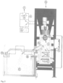
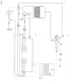
- the drying unit consists of the storage tank for the wet abrasive with the screw conveyor connecting it with the drying oven, the drying blower, the fine dust extractor, the screening unit / separator, the storage tank for the dry screened recycled abrasive and the storage tank for the dry coarse waste.
- the drying oven contains electric heating elements, inlet for air from the drying blower, temperature sensor, outlet for dry recycled material and inlet into the fine dust extractor which separates the dry fine dust and the clean air.
- the drying oven is aerated with pre-heated air brought in by the drying blower, which keeps the abrasive afloat thereby speeding up the drying process.
- the same air stream conveys the particles of dry screened recycled abrasive through the outlet for the dry recycled abrasive from the drying oven to the output vibrating separator from which the dried abrasive material passes through the screen and falls into the storage tank; any larger particles formed in the drying oven due to high temperatures, which may cause "sintering" together the particles so they cannot pass through the screen, are conveyed into a small container for the waste material.
- the storage tank for screened recycled material is provided with a vault disrupter and drainage to remove the displaced waste water.
- the primary requirement for operating the drying unit is to regulate batching of the abrasive depending on the temperature in the drying oven which is maintained at the range of 130-180 °C.
- the temperature in the drying oven is reduced by adding wet abrasive and increased by switching on the heating elements while the speed of batching of the abrasive is adjusted according to decrease or increase of the temperature in the drying oven. If the temperature in the drying oven is high, the speed of batching is increased; if the temperature in the drying oven is low, the speed of batching is reduced while waiting until the abrasive in the oven becomes dry.
- the adjusting system When starting the drying process, after switching the heating elements on for the first time the adjusting system is turned on.
- This system records the actual temperature in the drying oven measured by the temperature sensor and adjusts the speed of the screw conveyor and increases the intensity of batching. If the temperature in the drying oven exceeds the specified limit, heating elements are switched off and the intensity of batching is increased by a specified percentage step. If the temperature in the drying oven drops below a specified level, the batching process is turned off and the intensity of batching is reduced by a specified percentage step of the actual batching input; when the temperature again increases above the required level, the batching process is turned on.
- the system will adjust the intensity of batching according to the last operation carried out: Adjusting speed of batching Actual operation Last operation Switching off heating elements Turning off batching operation Switching off heating elements + specified operation - last change / 2 Turning of batching operation + last change / 2 - specified operation
- the primary requirement for operating the drying unit is to regulate batching of the abrasive according to the temperature in the drying oven.
- the control system continuously measures the current temperature and on the basis of this data it decides on the following:
- the equipment is controlled by the programmable logic controller (PLC), which ensures continuous operation and minimizes the need for control by an operator.
- PLC programmable logic controller
- average processing capacity of the equipment was 101.4 kg/hour of abrasive. Since at the start of the drying process the abrasive in the storage tank contains a greater proportion of water than at the end of the drying process, the storage tank has its own drainage system and the water is displaced from the stored wet abrasive.
- the drying unit operates automatically and its output is the dry abrasive suitable for immediate use for abrasive waterjet cutting or which can be stored for the later use.
- the storage conditions for recycled abrasive are the same as for new, unused abrasive.
- the drying process takes place in a drying oven, which can be operated separately or as part of the drying unit or the entire drying system for recycled abrasive.
- the drying unit is operated intermittently - that is, it only make sense to start the drying process if there is sufficient quantity of the wet abrasive in the storage tank. Consequently, it is possible to join the operation of this equipment with the operation of the cutting table, because the drying unit does not require constant supervision, even if the storage tank is getting filled up with the screened wet recycled abrasive from an external source.
- the whole equipment is designed to be controlled automatically, this includes the signalling of operating, restricting and defective conditions.
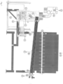
- the control process is used in working cycles shown in Figs. 4 and 5 - the separation of cutting sludge, where batches of sludge going into the drying oven are exactly measured, and in the drying process (shown in Fig. 3 ) where the abrasive going into the drying oven is exactly measured so as to achieve the maximum efficiency of the drying process, i.e. to minimise the power consumption per unit weight of abrasive.
- This method helps to increase the productivity of the specified recycling unit while greatly reducing the operating costs per unit weight of the recycled abrasive. This will allow this recycling unit to be used by also clients whose annual consumption of abrasive is relatively low. It will also disprove the long established view that recycling used abrasive is not economically viable. Finally, it will also help to significantly reduce the quantity of waste materials produced by machines working with high pressure abrasive waterjet.
- This control process also allows to significantly speed up the recycling process and greatly reduce the energy consumption costs - by up to 300-400% compared with the current situation.
- the capacity of drying system was 0.4-3.5 kg of abrasive per minute.
- the process of separating cutting sludge is as follows: From the trap 13 on the cutting table, the cutting sludge H is removed by means of a pumping unit in the sludge separating unit 14 to a screening unit 15 which consists of a vibrating separator 16 with steel screens or screens made from other materials of suitable mesh size depending on the required size of abrasive fraction which we want to obtain.
- the screening unit 15 will separate the cutting sludge H into the following groups:
- the reusable abrasive A is from the screening unit 15 conveyed into a suitable container, for example a bulk bag; the materials with different size of particles are taken to the other storage tanks depending on the type of their further use (for example, the material with smaller particles can be used for other purposes than abrasive waterjet cutting) or they are disposed of as waste materials.
- a suitable container for example a bulk bag
- the materials with different size of particles are taken to the other storage tanks depending on the type of their further use (for example, the material with smaller particles can be used for other purposes than abrasive waterjet cutting) or they are disposed of as waste materials.
- the drying unit for recycled material consisted of the storage tank 1 for wet abrasive with the screw conveyor 3 connecting it to the drying oven 4 , the drying blower 7 , the fine dust extractor 13 , the vibrating separator 8 , the bulk bag 9 for the dry screened recycled abrasive C and the container 10 for dry coarse waste D .
- the screw conveyor 3 went into the drying oven 4 which contained electric heating elements 6 , inlet for air from the drying blower 7 , pressure sensor 11 , temperature sensors 5 , outlet for dry recycled material and outlet into the fine dust extractor 13 which separated the dry fine dust G and the clean air E .
- the drying oven 4 was aerated with pre-heated air E brought in by the drying blower 7 , which kept the abrasive A afloat thereby speeding up the drying process.
- the same stream of air E was conveying the particles of dry screened recycled abrasive C through the outlet B for dry recycled abrasive from the drying oven 4 to the output vibrating separator 8 from which the dried abrasive material was passing through the screen and falling into the storage tank 9 which was a 1000 kg bulk bag; any larger particles D formed in the drying oven 4 due to high temperatures, which may cause "sintering" together the particles of dry material, were conveyed into a small container 10 for the waste material.
- the drying oven 4 was also connected to the fine dust extractor 13 which was extracting the residual dust G from the screened recycled abrasive thereby ensuring the dust-free operation of the drying unit.
- the storage tank 1 for the screened recycled material was provided with the vault disrupter 2 and the drainage 12 to remove the displaced waste water F .
- the storage tank for wet abrasive 1 was filled with the recycled abrasive, specifically the almandine garnet of Australian origin, weight 1000 kg, particles size 150-300 ⁇ m, 80 mesh.
- the temperature in the drying oven started decreasing; when the temperature dropped to 155 °C, the heating elements were switched on again and when the temperature dropped again to 140 °C, the batching of abrasive was turned off. The temperature then dropped to 138 °C. As the abrasive was aerated and continued to warm up, it gradually started drying and the temperature in the oven started to rise and after 5 minutes the temperature rose to 170 °C. As soon as the temperature rose to 150 °C, the batching of abrasive was turned on again. When the temperature rose again to 160 °C, the heating elements were switched off again.
- the adjusting system After switching the heating elements on for the first time the adjusting system was turned on. This system adjusts the speed of the screw conveyor 3 , thereby adjusting the intensity of batching. As the temperature in the drying oven exceeded the specified limit, i.e. 160 °C, heating elements were switched off and the intensity of batching was increased by a specified percentage step, that is, by 5 %. As soon as the temperature in the drying oven dropped below a specified level of 140 °C, the batching process was turned off and the intensity of batching was reduced by a specified 5 % of the actual batching input; when the temperature again rose above 150 °C, the batching process was turned on.
- the specified limit i.e. 160 °C
- the system started the adjusting process only after the heating elements were switched off for the first time, it removed the transient stage when the temperature in the oven rises to over 160 °C despite continued adding of the very wet abrasive material (due to the presence of old dry abrasive). Without this step, the system would increase the intensity of batching too soon.
- the system adjusted the intensity of batching according to the last operation carried out: Adjusting speed of batching Actual operation Last operation Switching off heating elements Turning off batching operation Switching off heating elements + specified operation - last change / 2 Turning of batching operation + last change / 2 - specified operation
- the primary requirement for operating the drying unit is to regulate batching of the abrasive according to the temperature in the drying oven.
- the control system continuously measures the current temperature and on the basis of this data it decides on the following:
- Cutting sludge H was pumped from the cutting table 20 onto a flat vibrating separator 16 which separated smaller and larger particles from the 80 mesh wet screened abrasive. From the vibrating separator 16 this wet abrasive 20 was falling into the textile bulk bag 17 . When this bulk bag 17 was filled with the wet abrasive A, it was hung in the open air for 3 days for the excess water to be displaced or trickle off. The content of this bag was then poured into the storage tank 1 for the wet recycled abrasive A in the drying unit.
- Cutting sludge H was removed from the cutting table 20 and put into the storage tank 18 for cutting sludge H .
- the cutting sludge H was conveyed by the screw conveyor onto the flat vibrating separator 16 which separated the 50 mesh wet screened abrasive into two fractions: the undersize fraction, which consisted of water I with fine waste and the oversize fraction, which contained the wet recycled abrasive A .
- the wet recycled abrasive A was conveyed into the bulk bag 17 and water I with fine waste was taken into the bulk bag 22 .
- the content of this bag 17 which was the wet recycled abrasive A, was then poured into the storage tank 1 for the wet recycled abrasive A in the drying unit.
- the drying unit for recycled material consisted of the storage tank 1 for wet abrasive A with the screw conveyor 3 connecting it to the drying oven 4, the drying blower 7 , the fine dust extractor 13 , the vibrating separator 8 , the bulk bag 9 for the dry screened recycled abrasive C and the container 10 for dry coarse waste D .
- the screw conveyor 3 went into the drying oven 4 which contained electric heating elements 6 , inlet for air from the drying blower 7 , pressure sensor 11 , temperature sensors 5 , outlet for dry recycled material and outlet into the fine dust extractor 13 which separated the dry fine dust G and the clean air E .
- the drying process was started, specifically the drying blower 7 of the drying oven 4 , the transport blower, the output vibrating separator 8 and the heating elements 5 .
- the system waited until the starting operating temperature, which was set to 150 °C, was reached.
- the system started batching abrasive A into the drying oven 4 using the screw conveyor 3 at the minimum specified intensity, which was 0.4 kg per minute.
- the temperature reached 160 °C the heating elements were switched off.
- the temperature in the drying oven started decreasing; when the temperature dropped to 155 °C, the heating elements were switched on again and when the temperature dropped again to 140 °C, the batching of abrasive was turned off.
- the abrasive was aerated and continued to warm up it gradually started drying and the temperature in the oven started to rise and after 5 minutes the temperature rose again to 170 °C.
- the batching of abrasive was turned on again.
- the heating elements were switched off again.
- the drying oven 4 was aerated with pre-heated air E brought in by the drying blower 7 , which kept the abrasive A afloat thereby speeding up the drying process.
- the adjusting system After switching the heating elements on for the first time the adjusting system was turned on. This system adjusts the speed of the screw conveyor 3 , thereby adjusting the intensity of batching. As the temperature in the drying oven exceeded the specified limit, i.e. 160 °C, heating elements were switched off and the intensity of batching was increased by a specified percentage step, that is, by 5 %. As soon as the temperature in the drying oven dropped below a specified level of 140 °C, the batching process was turned off and the intensity of batching was reduced by a specified 5% of the actual batching input; when the temperature again rose above 150 °C, the batching process was turned on
- the system started the adjusting process only after the heating elements were switched off for the first time, it removed the transient stage when the temperature in the oven rises to over 160 °C despite continued adding of the very wet abrasive material (due to the presence of old dry abrasive). Without this step, the system would increase the intensity of batching too soon.
- the system adjusted the intensity of batching according to the last operation carried out: Adjusting speed of batching Actual operation Last operation Switching off heating elements Turning off batching operation Switching off heating elements + specified operation - last change / 2 Turning of batching operation + last change / 2 - specified operation
- the stream of air E was conveying the particles of dry screened recycled abrasive C through the outlet B for dry recycled abrasive from the drying oven 4 to the output vibrating separator 8 from which the dried abrasive material was passed through the screen and fell into the storage tank 9 which was a 1000 kg bulk bag; any larger particles D formed in the drying oven 4 due to high temperatures, which may cause "sintering" together the particles of dry material, were conveyed into a small container 10 for the waste material.
- the drying oven 4 was also connected to the fine dust extractor 13 which was extracting the residual dust G from the screened recycled abrasive thereby ensuring the dust-free operation of the drying unit.
- the storage tank 1 for the screened recycled material was provided with the vault disrupter 2 and the drainage 12 to remove the displaced waste water F .
- High pressure waterjet cutting accessories for CNC machines for the high pressure waterjet cutting. Recycling the abrasive materials used for the high pressure waterjet cutting.
Landscapes
- Engineering & Computer Science (AREA)
- Mechanical Engineering (AREA)
- General Engineering & Computer Science (AREA)
- Life Sciences & Earth Sciences (AREA)
- Microbiology (AREA)
- Manufacture And Refinement Of Metals (AREA)
- Treatment Of Sludge (AREA)
Claims (5)
- Verfahren zum Recycling von für das Hochdruck-Wasserstrahlschneiden verwendetem Schleifmittel aus Schneidschlamm, wobei der Schneidschlamm einem Vibrationsabscheider (16) zugeführt wird, der kleinere und größere Partikel von dem Schleifmittel trennt, das dann in einen wasserdurchlässigen Behälter (17) abgeschieden wird; nach Verdrängung überschüssigen Wassers wird ein Nassschleifmittel (A) in einen Vorratsbehälter (1) für Nassschleifmittel (A) gegeben, von einem Förderer (3) zu einem Trocknungsofen (4) gefördert, der durch Heizelemente (6) beheizt und mit erwärmter Luft (E) belüftet wird; wobei die Partikel des Trockenschleifmittels (C) durch einen Auslass (B) für trockenes Recyclingschleifmittel aus dem Trocknungsofen (4) zu einem Ausgangs-Vibrationsabscheider (8) gefördert werden, aus dem getrocknetes Schleifmittel (C) durch das Sieb geleitet und in einen Vorratsbehälter/Schüttgutsack (9) für das trockene Recyclingschleifmittel (C) gegeben wird, wobei das Verfahren dadurch gekennzeichnet ist, dassdas Nassschleifmittel durch eine Förderschnecke gefördert wird, wobeidie Trocknungskapazität 101,4 kg/Stunde beträgt, wobeider Trocknungsofen (4) mit vorgewärmter, von einem Trockengebläse (7) zugeführter Luft belüftet wird, die das Nassschleifmittel (A) schwebend hält,wobei das Verfahren ferner dadurch gekennzeichnet ist, dassdie Temperatur im Trocknungsofen (4) im Bereich bis 130 °C bis 180 °C durch Aus- und Einschalten der Heizelemente (6) und eine Intensität der Dosierung des nassgesiebten recycelten Schleifmittels (A), das durch die Förderschnecke (3) gefördert wird, geregelt wird, wobeiein Einstellvorgang gestartet wird, nachdem die Heizelemente (6) zum ersten Mal ausgeschaltet wurden, die Heizelemente (6) ausgeschaltet werden, wenn die Temperatur im Trocknungsofen (4) 160 °C übersteigt, und eingeschaltet werden, wenn die Temperatur im Trocknungsofen (4) unter 155 °C sinkt, und die Dosierung von Nassschleifmittel (A) ausgeschaltet wird, wenn die Temperatur unter 140 °C fällt, und eingeschaltet wird, wenn die Temperatur wieder ansteigt, wobei beim Ausschalten der Heizelemente (6) die Intensität der Dosierung von Nassschleifmittel (A) um einen angegebenen Schritt erhöht wird, beim Ausschalten der Dosierung von Nassschleifmittel (A) die Intensität der Dosierung von Nassschleifmittel (A) um den angegebenen Schritt verringert wird, beim Ausschalten der Dosierung von Nassschleifmittel (A) im Anschluss an das Ausschalten der Heizelemente (6) die Intensität der Dosierung um die Hälfte des letzten angegebenen Schritts verringert wird und beim Ausschalten der Heizelemente (6) im Anschluss an das Ausschalten der Dosierung von Nassschleifmittel (A) die Intensität der Dosierung um die Hälfte des letzten angegebenen Schritts erhöht wird.
- Das Verfahren zum Recycling von für das Hochdruck-Wasserstrahlschneiden verwendetem Schleifmaterial aus Schneidschlamm nach Anspruch 1 ist dadurch gekennzeichnet, dass der angegebene Schritt 5 % der tatsächlichen Dosierintensität beträgt.
- Das Verfahren zum Recycling von Schleifmaterial, das zum Hochdruck-Wasserstrahlschneiden aus Schneidschlamm nach einem der Ansprüche 1 bis 2 verwendet wird, ist dadurch gekennzeichnet, dass der Trocknungsofen (4) mit dem Feinstaubabsauger (13) verbunden ist, der den Reststaub (G) abgesaugt hat.
- Das Verfahren zum Recycling von Schleifmaterial, das zum Hochdruck-Wasserstrahlschneiden aus Schneidschlamm nach einem der Ansprüche 1 bis 3 verwendet wird, ist dadurch gekennzeichnet, dass das verdrängte Abwasser (F) durch Drainage (12) aus dem Vorratsbehälter (1) entfernt wurde.
- Das Verfahren zum Recycling von Schleifmaterial, das zum Hochdruck-Wasserstrahlschneiden aus Schneidschlamm nach einem der Ansprüche 1 bis 4 verwendet wird, ist dadurch gekennzeichnet, dass das nassgesiebte Schleifmittel im Vorratsbehälter (1) mechanisch durch den Gewölbebrecher (2) geharkt wurde.
Applications Claiming Priority (1)
| Application Number | Priority Date | Filing Date | Title |
|---|---|---|---|
| CZ2015-961A CZ2015961A3 (cs) | 2015-12-31 | 2015-12-31 | Způsob recyklace abraziva z řezání vysokotlakým vodním paprskem z řezacího kalu a zařízení k provádění tohoto způsobu |
Publications (2)
| Publication Number | Publication Date |
|---|---|
| EP3187308A1 EP3187308A1 (de) | 2017-07-05 |
| EP3187308B1 true EP3187308B1 (de) | 2024-02-07 |
Family
ID=57544292
Family Applications (1)
| Application Number | Title | Priority Date | Filing Date |
|---|---|---|---|
| EP16203479.7A Active EP3187308B1 (de) | 2015-12-31 | 2016-12-12 | Verfahren zum recyceln eines abrasivstoffs zum hochdruckwasserstrahlschneiden aus schneidschlamm |
Country Status (4)
| Country | Link |
|---|---|
| US (1) | US10478944B2 (de) |
| EP (1) | EP3187308B1 (de) |
| CZ (1) | CZ2015961A3 (de) |
| EA (1) | EA036141B1 (de) |
Families Citing this family (4)
| Publication number | Priority date | Publication date | Assignee | Title |
|---|---|---|---|---|
| CN112318388B (zh) * | 2020-10-19 | 2021-09-10 | 燕山大学 | 用于处理喷砂机产生灰尘的水膜除尘装置 |
| CN113084712B (zh) * | 2021-03-09 | 2022-08-09 | 山东开泰抛丸机械股份有限公司 | 抛丸清理装置 |
| CN114190789A (zh) * | 2021-12-15 | 2022-03-18 | 昆明弘承食品科技有限公司 | 一种用于果蔬集成细胞破壁装置及使用方法 |
| CN114434344B (zh) * | 2022-01-12 | 2022-12-09 | 武汉大学 | 一种高压磨料水射流钢轨打磨磨料分离循环利用系统 |
Family Cites Families (12)
| Publication number | Priority date | Publication date | Assignee | Title |
|---|---|---|---|---|
| SU897491A1 (ru) * | 1980-05-29 | 1982-01-15 | Днепропетровский Металлургический Институт | Установка дл гидроабразивной обработки деталей |
| US5468174A (en) * | 1992-11-13 | 1995-11-21 | Ipec Advanced Systems, Inc. | Recyclable abrasive blasting system |
| DE19645142A1 (de) * | 1996-10-24 | 1998-04-30 | Intrec Ges Fuer Innovative Tec | Verfahren und Vorrichtung zum Recyceln von Sanden |
| US6328638B1 (en) * | 1998-04-28 | 2001-12-11 | Flow International Corporation | Apparatus and methods for recovering abrasive from an abrasive-laden fluid |
| WO2003068405A2 (en) * | 2002-02-13 | 2003-08-21 | Richel, Inc. | Granular material recovery system |
| DE10251792A1 (de) * | 2002-11-07 | 2004-05-19 | Industriebetriebe Heinrich Meyer-Werke Breloh Gmbh & Co. Kg | Verfahren zur Regenerierung von Filtermitteln, insbesondere Kieselgur |
| ITRM20050329A1 (it) * | 2005-06-24 | 2006-12-25 | Guido Fragiacomo | Procedimento per il trattamento di sospensioni abrasive esauste per il recupero delle loro componenti riciclabili e relativo impianto. |
| CA2624478A1 (en) * | 2005-10-07 | 2007-04-19 | Caretta Technology S.R.L. | Cutting unit with modular structure |
| US20080155904A1 (en) * | 2006-12-31 | 2008-07-03 | 3M Innovative Properties Company | Method of abrading a metal workpiece |
| US8920210B2 (en) * | 2009-06-18 | 2014-12-30 | Ronald C. Benson | System and method for drying grit used for abrasive blasting |
| CZ21487U1 (cs) | 2010-09-23 | 2010-11-11 | Plehaso, komanditní spolecnost | Zařízení na recyklaci abraziva |
| KR20130004686A (ko) * | 2011-07-04 | 2013-01-14 | 현대중공업 주식회사 | 연마재 재활용 장치 |
-
2015
- 2015-12-31 CZ CZ2015-961A patent/CZ2015961A3/cs unknown
-
2016
- 2016-12-12 EP EP16203479.7A patent/EP3187308B1/de active Active
- 2016-12-16 US US15/381,111 patent/US10478944B2/en active Active
- 2016-12-28 EA EA201692499A patent/EA036141B1/ru unknown
Also Published As
| Publication number | Publication date |
|---|---|
| EA201692499A1 (ru) | 2017-07-31 |
| US20170182631A1 (en) | 2017-06-29 |
| US10478944B2 (en) | 2019-11-19 |
| CZ306505B6 (cs) | 2017-02-15 |
| CZ2015961A3 (cs) | 2017-02-15 |
| EA036141B1 (ru) | 2020-10-02 |
| EP3187308A1 (de) | 2017-07-05 |
Similar Documents
| Publication | Publication Date | Title |
|---|---|---|
| EP3109002B1 (de) | Trocknungskammer, trocknungseinheit, trockner von wiederverwendetem schleifmittel und verfahren zum trocknen von feuchtem wiederverwendetem schleifmittel | |
| EP3187308B1 (de) | Verfahren zum recyceln eines abrasivstoffs zum hochdruckwasserstrahlschneiden aus schneidschlamm | |
| KR101433692B1 (ko) | 석고 폐재 재생 원료화 장치 | |
| RU2150385C1 (ru) | Способ переработки смесей пластмасс и установка для переработки смесей пластмасс | |
| RU2017142806A (ru) | Способ регенерации формовочного песка и оборудование регенерации | |
| WO2018108605A1 (en) | Method and apparatus for washing and grading sand | |
| CA2938322A1 (en) | Method and system for processing and recycling infill material of artificial turf | |
| CN203820648U (zh) | 干式机制砂楼式闭环生产设备 | |
| US20160369371A1 (en) | Metal recovery system and method | |
| WO2020002977A1 (en) | Systems and method for washing and grading particulate material. | |
| AU2019260555B2 (en) | System and method for an electrodynamic fragmentation | |
| US20160151884A1 (en) | Foreign object removal for abrasive recycling system | |
| KR20210033640A (ko) | 실리콘 원료칩의 선별 시스템 | |
| JPS628256B2 (de) | ||
| JP2011148166A (ja) | 樹脂塗膜剥離システム | |
| CN215140879U (zh) | 一种毛煤除杂的系统 | |
| KR102287042B1 (ko) | 다양한 소재의 분류를 위한 시스템, 장치, 및 공정 | |
| CA3098660C (en) | Method and apparatus for washing and grading sand | |
| CN104445852B (zh) | 一种含油污泥预处理方法及装置 | |
| CN205086221U (zh) | 一种塑料型材废料杂质分离装置 | |
| EP4166501A1 (de) | Verfahren zur rückgewinnung von gips aus gipsabfallplatten | |
| KR101215365B1 (ko) | 폐 전선 수지피복물 재활용을 위한 분쇄 및 공랭장치 | |
| CN205463125U (zh) | 一种回收粉料过筛装置 | |
| CN106738474A (zh) | 一种二次研磨型环保橡胶细碎机 | |
| CN203820647U (zh) | 干式机制砂楼式开环生产设备 |
Legal Events
| Date | Code | Title | Description |
|---|---|---|---|
| PUAI | Public reference made under article 153(3) epc to a published international application that has entered the european phase |
Free format text: ORIGINAL CODE: 0009012 |
|
| STAA | Information on the status of an ep patent application or granted ep patent |
Free format text: STATUS: THE APPLICATION HAS BEEN PUBLISHED |
|
| AK | Designated contracting states |
Kind code of ref document: A1 Designated state(s): AL AT BE BG CH CY CZ DE DK EE ES FI FR GB GR HR HU IE IS IT LI LT LU LV MC MK MT NL NO PL PT RO RS SE SI SK SM TR |
|
| AX | Request for extension of the european patent |
Extension state: BA ME |
|
| STAA | Information on the status of an ep patent application or granted ep patent |
Free format text: STATUS: REQUEST FOR EXAMINATION WAS MADE |
|
| 17P | Request for examination filed |
Effective date: 20180105 |
|
| RBV | Designated contracting states (corrected) |
Designated state(s): AL AT BE BG CH CY CZ DE DK EE ES FI FR GB GR HR HU IE IS IT LI LT LU LV MC MK MT NL NO PL PT RO RS SE SI SK SM TR |
|
| STAA | Information on the status of an ep patent application or granted ep patent |
Free format text: STATUS: EXAMINATION IS IN PROGRESS |
|
| 17Q | First examination report despatched |
Effective date: 20210211 |
|
| STAA | Information on the status of an ep patent application or granted ep patent |
Free format text: STATUS: EXAMINATION IS IN PROGRESS |
|
| GRAP | Despatch of communication of intention to grant a patent |
Free format text: ORIGINAL CODE: EPIDOSNIGR1 |
|
| STAA | Information on the status of an ep patent application or granted ep patent |
Free format text: STATUS: GRANT OF PATENT IS INTENDED |
|
| INTG | Intention to grant announced |
Effective date: 20230830 |
|
| GRAS | Grant fee paid |
Free format text: ORIGINAL CODE: EPIDOSNIGR3 |
|
| GRAA | (expected) grant |
Free format text: ORIGINAL CODE: 0009210 |
|
| STAA | Information on the status of an ep patent application or granted ep patent |
Free format text: STATUS: THE PATENT HAS BEEN GRANTED |
|
| AK | Designated contracting states |
Kind code of ref document: B1 Designated state(s): AL AT BE BG CH CY CZ DE DK EE ES FI FR GB GR HR HU IE IS IT LI LT LU LV MC MK MT NL NO PL PT RO RS SE SI SK SM TR |
|
| REG | Reference to a national code |
Ref country code: GB Ref legal event code: FG4D |
|
| REG | Reference to a national code |
Ref country code: CH Ref legal event code: EP |
|
| REG | Reference to a national code |
Ref country code: IE Ref legal event code: FG4D |
|
| REG | Reference to a national code |
Ref country code: DE Ref legal event code: R096 Ref document number: 602016085656 Country of ref document: DE |
|
| REG | Reference to a national code |
Ref country code: LT Ref legal event code: MG9D |
|
| REG | Reference to a national code |
Ref country code: NL Ref legal event code: MP Effective date: 20240207 |
|
| PG25 | Lapsed in a contracting state [announced via postgrant information from national office to epo] |
Ref country code: IS Free format text: LAPSE BECAUSE OF FAILURE TO SUBMIT A TRANSLATION OF THE DESCRIPTION OR TO PAY THE FEE WITHIN THE PRESCRIBED TIME-LIMIT Effective date: 20240607 |
|
| PG25 | Lapsed in a contracting state [announced via postgrant information from national office to epo] |
Ref country code: LT Free format text: LAPSE BECAUSE OF FAILURE TO SUBMIT A TRANSLATION OF THE DESCRIPTION OR TO PAY THE FEE WITHIN THE PRESCRIBED TIME-LIMIT Effective date: 20240207 |
|
| PG25 | Lapsed in a contracting state [announced via postgrant information from national office to epo] |
Ref country code: GR Free format text: LAPSE BECAUSE OF FAILURE TO SUBMIT A TRANSLATION OF THE DESCRIPTION OR TO PAY THE FEE WITHIN THE PRESCRIBED TIME-LIMIT Effective date: 20240508 |
|
| REG | Reference to a national code |
Ref country code: AT Ref legal event code: MK05 Ref document number: 1655071 Country of ref document: AT Kind code of ref document: T Effective date: 20240207 |
|
| PG25 | Lapsed in a contracting state [announced via postgrant information from national office to epo] |
Ref country code: RS Free format text: LAPSE BECAUSE OF FAILURE TO SUBMIT A TRANSLATION OF THE DESCRIPTION OR TO PAY THE FEE WITHIN THE PRESCRIBED TIME-LIMIT Effective date: 20240507 Ref country code: NL Free format text: LAPSE BECAUSE OF FAILURE TO SUBMIT A TRANSLATION OF THE DESCRIPTION OR TO PAY THE FEE WITHIN THE PRESCRIBED TIME-LIMIT Effective date: 20240207 Ref country code: HR Free format text: LAPSE BECAUSE OF FAILURE TO SUBMIT A TRANSLATION OF THE DESCRIPTION OR TO PAY THE FEE WITHIN THE PRESCRIBED TIME-LIMIT Effective date: 20240207 |
|
| PG25 | Lapsed in a contracting state [announced via postgrant information from national office to epo] |
Ref country code: ES Free format text: LAPSE BECAUSE OF FAILURE TO SUBMIT A TRANSLATION OF THE DESCRIPTION OR TO PAY THE FEE WITHIN THE PRESCRIBED TIME-LIMIT Effective date: 20240207 |
|
| PG25 | Lapsed in a contracting state [announced via postgrant information from national office to epo] |
Ref country code: AT Free format text: LAPSE BECAUSE OF FAILURE TO SUBMIT A TRANSLATION OF THE DESCRIPTION OR TO PAY THE FEE WITHIN THE PRESCRIBED TIME-LIMIT Effective date: 20240207 |
|
| PG25 | Lapsed in a contracting state [announced via postgrant information from national office to epo] |
Ref country code: RS Free format text: LAPSE BECAUSE OF FAILURE TO SUBMIT A TRANSLATION OF THE DESCRIPTION OR TO PAY THE FEE WITHIN THE PRESCRIBED TIME-LIMIT Effective date: 20240507 Ref country code: NO Free format text: LAPSE BECAUSE OF FAILURE TO SUBMIT A TRANSLATION OF THE DESCRIPTION OR TO PAY THE FEE WITHIN THE PRESCRIBED TIME-LIMIT Effective date: 20240507 Ref country code: NL Free format text: LAPSE BECAUSE OF FAILURE TO SUBMIT A TRANSLATION OF THE DESCRIPTION OR TO PAY THE FEE WITHIN THE PRESCRIBED TIME-LIMIT Effective date: 20240207 Ref country code: LT Free format text: LAPSE BECAUSE OF FAILURE TO SUBMIT A TRANSLATION OF THE DESCRIPTION OR TO PAY THE FEE WITHIN THE PRESCRIBED TIME-LIMIT Effective date: 20240207 Ref country code: IS Free format text: LAPSE BECAUSE OF FAILURE TO SUBMIT A TRANSLATION OF THE DESCRIPTION OR TO PAY THE FEE WITHIN THE PRESCRIBED TIME-LIMIT Effective date: 20240607 Ref country code: HR Free format text: LAPSE BECAUSE OF FAILURE TO SUBMIT A TRANSLATION OF THE DESCRIPTION OR TO PAY THE FEE WITHIN THE PRESCRIBED TIME-LIMIT Effective date: 20240207 Ref country code: GR Free format text: LAPSE BECAUSE OF FAILURE TO SUBMIT A TRANSLATION OF THE DESCRIPTION OR TO PAY THE FEE WITHIN THE PRESCRIBED TIME-LIMIT Effective date: 20240508 Ref country code: FI Free format text: LAPSE BECAUSE OF FAILURE TO SUBMIT A TRANSLATION OF THE DESCRIPTION OR TO PAY THE FEE WITHIN THE PRESCRIBED TIME-LIMIT Effective date: 20240207 Ref country code: ES Free format text: LAPSE BECAUSE OF FAILURE TO SUBMIT A TRANSLATION OF THE DESCRIPTION OR TO PAY THE FEE WITHIN THE PRESCRIBED TIME-LIMIT Effective date: 20240207 Ref country code: BG Free format text: LAPSE BECAUSE OF FAILURE TO SUBMIT A TRANSLATION OF THE DESCRIPTION OR TO PAY THE FEE WITHIN THE PRESCRIBED TIME-LIMIT Effective date: 20240207 Ref country code: AT Free format text: LAPSE BECAUSE OF FAILURE TO SUBMIT A TRANSLATION OF THE DESCRIPTION OR TO PAY THE FEE WITHIN THE PRESCRIBED TIME-LIMIT Effective date: 20240207 |
|
| PG25 | Lapsed in a contracting state [announced via postgrant information from national office to epo] |
Ref country code: PT Free format text: LAPSE BECAUSE OF FAILURE TO SUBMIT A TRANSLATION OF THE DESCRIPTION OR TO PAY THE FEE WITHIN THE PRESCRIBED TIME-LIMIT Effective date: 20240607 Ref country code: PL Free format text: LAPSE BECAUSE OF FAILURE TO SUBMIT A TRANSLATION OF THE DESCRIPTION OR TO PAY THE FEE WITHIN THE PRESCRIBED TIME-LIMIT Effective date: 20240207 |
|
| PG25 | Lapsed in a contracting state [announced via postgrant information from national office to epo] |
Ref country code: SE Free format text: LAPSE BECAUSE OF FAILURE TO SUBMIT A TRANSLATION OF THE DESCRIPTION OR TO PAY THE FEE WITHIN THE PRESCRIBED TIME-LIMIT Effective date: 20240207 Ref country code: PT Free format text: LAPSE BECAUSE OF FAILURE TO SUBMIT A TRANSLATION OF THE DESCRIPTION OR TO PAY THE FEE WITHIN THE PRESCRIBED TIME-LIMIT Effective date: 20240607 Ref country code: PL Free format text: LAPSE BECAUSE OF FAILURE TO SUBMIT A TRANSLATION OF THE DESCRIPTION OR TO PAY THE FEE WITHIN THE PRESCRIBED TIME-LIMIT Effective date: 20240207 Ref country code: LV Free format text: LAPSE BECAUSE OF FAILURE TO SUBMIT A TRANSLATION OF THE DESCRIPTION OR TO PAY THE FEE WITHIN THE PRESCRIBED TIME-LIMIT Effective date: 20240207 |
|
| PG25 | Lapsed in a contracting state [announced via postgrant information from national office to epo] |
Ref country code: DK Free format text: LAPSE BECAUSE OF FAILURE TO SUBMIT A TRANSLATION OF THE DESCRIPTION OR TO PAY THE FEE WITHIN THE PRESCRIBED TIME-LIMIT Effective date: 20240207 |
|
| PG25 | Lapsed in a contracting state [announced via postgrant information from national office to epo] |
Ref country code: SM Free format text: LAPSE BECAUSE OF FAILURE TO SUBMIT A TRANSLATION OF THE DESCRIPTION OR TO PAY THE FEE WITHIN THE PRESCRIBED TIME-LIMIT Effective date: 20240207 |
|
| PG25 | Lapsed in a contracting state [announced via postgrant information from national office to epo] |
Ref country code: CZ Free format text: LAPSE BECAUSE OF FAILURE TO SUBMIT A TRANSLATION OF THE DESCRIPTION OR TO PAY THE FEE WITHIN THE PRESCRIBED TIME-LIMIT Effective date: 20240207 Ref country code: EE Free format text: LAPSE BECAUSE OF FAILURE TO SUBMIT A TRANSLATION OF THE DESCRIPTION OR TO PAY THE FEE WITHIN THE PRESCRIBED TIME-LIMIT Effective date: 20240207 |
|
| PG25 | Lapsed in a contracting state [announced via postgrant information from national office to epo] |
Ref country code: SK Free format text: LAPSE BECAUSE OF FAILURE TO SUBMIT A TRANSLATION OF THE DESCRIPTION OR TO PAY THE FEE WITHIN THE PRESCRIBED TIME-LIMIT Effective date: 20240207 |
|
| PG25 | Lapsed in a contracting state [announced via postgrant information from national office to epo] |
Ref country code: SM Free format text: LAPSE BECAUSE OF FAILURE TO SUBMIT A TRANSLATION OF THE DESCRIPTION OR TO PAY THE FEE WITHIN THE PRESCRIBED TIME-LIMIT Effective date: 20240207 Ref country code: SK Free format text: LAPSE BECAUSE OF FAILURE TO SUBMIT A TRANSLATION OF THE DESCRIPTION OR TO PAY THE FEE WITHIN THE PRESCRIBED TIME-LIMIT Effective date: 20240207 Ref country code: RO Free format text: LAPSE BECAUSE OF FAILURE TO SUBMIT A TRANSLATION OF THE DESCRIPTION OR TO PAY THE FEE WITHIN THE PRESCRIBED TIME-LIMIT Effective date: 20240207 Ref country code: EE Free format text: LAPSE BECAUSE OF FAILURE TO SUBMIT A TRANSLATION OF THE DESCRIPTION OR TO PAY THE FEE WITHIN THE PRESCRIBED TIME-LIMIT Effective date: 20240207 Ref country code: DK Free format text: LAPSE BECAUSE OF FAILURE TO SUBMIT A TRANSLATION OF THE DESCRIPTION OR TO PAY THE FEE WITHIN THE PRESCRIBED TIME-LIMIT Effective date: 20240207 Ref country code: CZ Free format text: LAPSE BECAUSE OF FAILURE TO SUBMIT A TRANSLATION OF THE DESCRIPTION OR TO PAY THE FEE WITHIN THE PRESCRIBED TIME-LIMIT Effective date: 20240207 |
|
| REG | Reference to a national code |
Ref country code: DE Ref legal event code: R097 Ref document number: 602016085656 Country of ref document: DE |
|
| PG25 | Lapsed in a contracting state [announced via postgrant information from national office to epo] |
Ref country code: IT Free format text: LAPSE BECAUSE OF FAILURE TO SUBMIT A TRANSLATION OF THE DESCRIPTION OR TO PAY THE FEE WITHIN THE PRESCRIBED TIME-LIMIT Effective date: 20240207 |
|
| PLBE | No opposition filed within time limit |
Free format text: ORIGINAL CODE: 0009261 |
|
| STAA | Information on the status of an ep patent application or granted ep patent |
Free format text: STATUS: NO OPPOSITION FILED WITHIN TIME LIMIT |
|
| PG25 | Lapsed in a contracting state [announced via postgrant information from national office to epo] |
Ref country code: IT Free format text: LAPSE BECAUSE OF FAILURE TO SUBMIT A TRANSLATION OF THE DESCRIPTION OR TO PAY THE FEE WITHIN THE PRESCRIBED TIME-LIMIT Effective date: 20240207 |
|
| 26N | No opposition filed |
Effective date: 20241108 |