EP3187285A1 - Poudre pour fabrication additive couche par couche et procédé pour la production d'objet par fabrication additive couche par couche - Google Patents
Poudre pour fabrication additive couche par couche et procédé pour la production d'objet par fabrication additive couche par couche Download PDFInfo
- Publication number
- EP3187285A1 EP3187285A1 EP15835169.2A EP15835169A EP3187285A1 EP 3187285 A1 EP3187285 A1 EP 3187285A1 EP 15835169 A EP15835169 A EP 15835169A EP 3187285 A1 EP3187285 A1 EP 3187285A1
- Authority
- EP
- European Patent Office
- Prior art keywords
- powder
- layer
- additive manufacturing
- metal powder
- solidified
- Prior art date
- Legal status (The legal status is an assumption and is not a legal conclusion. Google has not performed a legal analysis and makes no representation as to the accuracy of the status listed.)
- Granted
Links
- 239000000843 powder Substances 0.000 title claims abstract description 242
- 238000004519 manufacturing process Methods 0.000 title claims abstract description 69
- 239000000654 additive Substances 0.000 title claims abstract description 57
- 230000000996 additive effect Effects 0.000 title claims abstract description 57
- 238000000034 method Methods 0.000 title description 22
- 230000008569 process Effects 0.000 title description 3
- 229910052751 metal Inorganic materials 0.000 claims abstract description 70
- 239000002184 metal Substances 0.000 claims abstract description 70
- 238000002844 melting Methods 0.000 claims abstract description 21
- 230000008018 melting Effects 0.000 claims abstract description 21
- VYPSYNLAJGMNEJ-UHFFFAOYSA-N Silicium dioxide Chemical compound O=[Si]=O VYPSYNLAJGMNEJ-UHFFFAOYSA-N 0.000 claims description 12
- 238000003892 spreading Methods 0.000 claims description 9
- 230000007480 spreading Effects 0.000 claims description 9
- 239000000377 silicon dioxide Substances 0.000 claims description 6
- PNEYBMLMFCGWSK-UHFFFAOYSA-N aluminium oxide Inorganic materials [O-2].[O-2].[O-2].[Al+3].[Al+3] PNEYBMLMFCGWSK-UHFFFAOYSA-N 0.000 claims description 4
- 239000000919 ceramic Substances 0.000 claims description 2
- 230000001678 irradiating effect Effects 0.000 claims 1
- 239000000956 alloy Substances 0.000 description 36
- 229910045601 alloy Inorganic materials 0.000 description 36
- 239000000463 material Substances 0.000 description 34
- 238000010438 heat treatment Methods 0.000 description 32
- 239000002245 particle Substances 0.000 description 15
- 230000000052 comparative effect Effects 0.000 description 14
- 239000000203 mixture Substances 0.000 description 9
- 238000009826 distribution Methods 0.000 description 6
- 230000002829 reductive effect Effects 0.000 description 6
- 238000001816 cooling Methods 0.000 description 5
- 230000000694 effects Effects 0.000 description 5
- 238000007711 solidification Methods 0.000 description 5
- 230000008023 solidification Effects 0.000 description 5
- 239000011800 void material Substances 0.000 description 5
- 239000012298 atmosphere Substances 0.000 description 4
- 239000006185 dispersion Substances 0.000 description 4
- 238000010894 electron beam technology Methods 0.000 description 4
- 239000010419 fine particle Substances 0.000 description 4
- 238000002156 mixing Methods 0.000 description 4
- RYGMFSIKBFXOCR-UHFFFAOYSA-N Copper Chemical compound [Cu] RYGMFSIKBFXOCR-UHFFFAOYSA-N 0.000 description 3
- 238000000889 atomisation Methods 0.000 description 3
- 230000015572 biosynthetic process Effects 0.000 description 3
- 238000004093 laser heating Methods 0.000 description 3
- XKRFYHLGVUSROY-UHFFFAOYSA-N Argon Chemical compound [Ar] XKRFYHLGVUSROY-UHFFFAOYSA-N 0.000 description 2
- 229910000975 Carbon steel Inorganic materials 0.000 description 2
- 239000010962 carbon steel Substances 0.000 description 2
- 238000002074 melt spinning Methods 0.000 description 2
- 239000012299 nitrogen atmosphere Substances 0.000 description 2
- 230000005855 radiation Effects 0.000 description 2
- 239000002994 raw material Substances 0.000 description 2
- 102200082816 rs34868397 Human genes 0.000 description 2
- 238000005245 sintering Methods 0.000 description 2
- 238000003980 solgel method Methods 0.000 description 2
- 239000000725 suspension Substances 0.000 description 2
- 238000010558 suspension polymerization method Methods 0.000 description 2
- 238000003786 synthesis reaction Methods 0.000 description 2
- 229910002012 Aerosil® Inorganic materials 0.000 description 1
- 230000009471 action Effects 0.000 description 1
- 238000005054 agglomeration Methods 0.000 description 1
- 230000002776 aggregation Effects 0.000 description 1
- 229910052786 argon Inorganic materials 0.000 description 1
- 230000008901 benefit Effects 0.000 description 1
- 230000008859 change Effects 0.000 description 1
- 229910052804 chromium Inorganic materials 0.000 description 1
- 239000013078 crystal Substances 0.000 description 1
- 238000005520 cutting process Methods 0.000 description 1
- 230000002950 deficient Effects 0.000 description 1
- 230000008021 deposition Effects 0.000 description 1
- 239000000428 dust Substances 0.000 description 1
- 238000005868 electrolysis reaction Methods 0.000 description 1
- 230000003028 elevating effect Effects 0.000 description 1
- 238000011156 evaluation Methods 0.000 description 1
- 238000004880 explosion Methods 0.000 description 1
- 239000007789 gas Substances 0.000 description 1
- 238000009689 gas atomisation Methods 0.000 description 1
- 230000005484 gravity Effects 0.000 description 1
- 239000007943 implant Substances 0.000 description 1
- 230000006872 improvement Effects 0.000 description 1
- 239000011261 inert gas Substances 0.000 description 1
- 229910010272 inorganic material Inorganic materials 0.000 description 1
- 239000011147 inorganic material Substances 0.000 description 1
- 229910052742 iron Inorganic materials 0.000 description 1
- 239000000155 melt Substances 0.000 description 1
- 150000002739 metals Chemical class 0.000 description 1
- 239000011859 microparticle Substances 0.000 description 1
- 229910052759 nickel Inorganic materials 0.000 description 1
- 230000003647 oxidation Effects 0.000 description 1
- 238000007254 oxidation reaction Methods 0.000 description 1
- 238000002360 preparation method Methods 0.000 description 1
- 230000009257 reactivity Effects 0.000 description 1
- 230000003014 reinforcing effect Effects 0.000 description 1
- 239000011347 resin Substances 0.000 description 1
- 229920005989 resin Polymers 0.000 description 1
- 238000005096 rolling process Methods 0.000 description 1
- 239000006104 solid solution Substances 0.000 description 1
- 239000000243 solution Substances 0.000 description 1
- 238000005728 strengthening Methods 0.000 description 1
- 239000000758 substrate Substances 0.000 description 1
- 230000003746 surface roughness Effects 0.000 description 1
- 239000004094 surface-active agent Substances 0.000 description 1
- 238000009692 water atomization Methods 0.000 description 1
Images

Classifications
-
- B—PERFORMING OPERATIONS; TRANSPORTING
- B22—CASTING; POWDER METALLURGY
- B22F—WORKING METALLIC POWDER; MANUFACTURE OF ARTICLES FROM METALLIC POWDER; MAKING METALLIC POWDER; APPARATUS OR DEVICES SPECIALLY ADAPTED FOR METALLIC POWDER
- B22F1/00—Metallic powder; Treatment of metallic powder, e.g. to facilitate working or to improve properties
- B22F1/05—Metallic powder characterised by the size or surface area of the particles
- B22F1/052—Metallic powder characterised by the size or surface area of the particles characterised by a mixture of particles of different sizes or by the particle size distribution
-
- B—PERFORMING OPERATIONS; TRANSPORTING
- B22—CASTING; POWDER METALLURGY
- B22F—WORKING METALLIC POWDER; MANUFACTURE OF ARTICLES FROM METALLIC POWDER; MAKING METALLIC POWDER; APPARATUS OR DEVICES SPECIALLY ADAPTED FOR METALLIC POWDER
- B22F10/00—Additive manufacturing of workpieces or articles from metallic powder
- B22F10/20—Direct sintering or melting
- B22F10/28—Powder bed fusion, e.g. selective laser melting [SLM] or electron beam melting [EBM]
-
- B—PERFORMING OPERATIONS; TRANSPORTING
- B29—WORKING OF PLASTICS; WORKING OF SUBSTANCES IN A PLASTIC STATE IN GENERAL
- B29C—SHAPING OR JOINING OF PLASTICS; SHAPING OF MATERIAL IN A PLASTIC STATE, NOT OTHERWISE PROVIDED FOR; AFTER-TREATMENT OF THE SHAPED PRODUCTS, e.g. REPAIRING
- B29C67/00—Shaping techniques not covered by groups B29C39/00 - B29C65/00, B29C70/00 or B29C73/00
-
- B—PERFORMING OPERATIONS; TRANSPORTING
- B33—ADDITIVE MANUFACTURING TECHNOLOGY
- B33Y—ADDITIVE MANUFACTURING, i.e. MANUFACTURING OF THREE-DIMENSIONAL [3-D] OBJECTS BY ADDITIVE DEPOSITION, ADDITIVE AGGLOMERATION OR ADDITIVE LAYERING, e.g. BY 3-D PRINTING, STEREOLITHOGRAPHY OR SELECTIVE LASER SINTERING
- B33Y70/00—Materials specially adapted for additive manufacturing
- B33Y70/10—Composites of different types of material, e.g. mixtures of ceramics and polymers or mixtures of metals and biomaterials
-
- B—PERFORMING OPERATIONS; TRANSPORTING
- B22—CASTING; POWDER METALLURGY
- B22F—WORKING METALLIC POWDER; MANUFACTURE OF ARTICLES FROM METALLIC POWDER; MAKING METALLIC POWDER; APPARATUS OR DEVICES SPECIALLY ADAPTED FOR METALLIC POWDER
- B22F10/00—Additive manufacturing of workpieces or articles from metallic powder
- B22F10/30—Process control
- B22F10/32—Process control of the atmosphere, e.g. composition or pressure in a building chamber
-
- B—PERFORMING OPERATIONS; TRANSPORTING
- B22—CASTING; POWDER METALLURGY
- B22F—WORKING METALLIC POWDER; MANUFACTURE OF ARTICLES FROM METALLIC POWDER; MAKING METALLIC POWDER; APPARATUS OR DEVICES SPECIALLY ADAPTED FOR METALLIC POWDER
- B22F10/00—Additive manufacturing of workpieces or articles from metallic powder
- B22F10/30—Process control
- B22F10/34—Process control of powder characteristics, e.g. density, oxidation or flowability
-
- B—PERFORMING OPERATIONS; TRANSPORTING
- B33—ADDITIVE MANUFACTURING TECHNOLOGY
- B33Y—ADDITIVE MANUFACTURING, i.e. MANUFACTURING OF THREE-DIMENSIONAL [3-D] OBJECTS BY ADDITIVE DEPOSITION, ADDITIVE AGGLOMERATION OR ADDITIVE LAYERING, e.g. BY 3-D PRINTING, STEREOLITHOGRAPHY OR SELECTIVE LASER SINTERING
- B33Y80/00—Products made by additive manufacturing
-
- C—CHEMISTRY; METALLURGY
- C22—METALLURGY; FERROUS OR NON-FERROUS ALLOYS; TREATMENT OF ALLOYS OR NON-FERROUS METALS
- C22C—ALLOYS
- C22C32/00—Non-ferrous alloys containing at least 5% by weight but less than 50% by weight of oxides, carbides, borides, nitrides, silicides or other metal compounds, e.g. oxynitrides, sulfides, whether added as such or formed in situ
- C22C32/001—Non-ferrous alloys containing at least 5% by weight but less than 50% by weight of oxides, carbides, borides, nitrides, silicides or other metal compounds, e.g. oxynitrides, sulfides, whether added as such or formed in situ with only oxides
- C22C32/0015—Non-ferrous alloys containing at least 5% by weight but less than 50% by weight of oxides, carbides, borides, nitrides, silicides or other metal compounds, e.g. oxynitrides, sulfides, whether added as such or formed in situ with only oxides with only single oxides as main non-metallic constituents
-
- Y—GENERAL TAGGING OF NEW TECHNOLOGICAL DEVELOPMENTS; GENERAL TAGGING OF CROSS-SECTIONAL TECHNOLOGIES SPANNING OVER SEVERAL SECTIONS OF THE IPC; TECHNICAL SUBJECTS COVERED BY FORMER USPC CROSS-REFERENCE ART COLLECTIONS [XRACs] AND DIGESTS
- Y02—TECHNOLOGIES OR APPLICATIONS FOR MITIGATION OR ADAPTATION AGAINST CLIMATE CHANGE
- Y02P—CLIMATE CHANGE MITIGATION TECHNOLOGIES IN THE PRODUCTION OR PROCESSING OF GOODS
- Y02P10/00—Technologies related to metal processing
- Y02P10/25—Process efficiency
Definitions
- the present invention relates to a powder for additive manufacturing and a method for producing a multi-layer shaped object.
- Additive manufacturing using a metal powder as a raw material is known as a technique capable of directly obtaining a member having a three-dimensional shape.
- a technique is roughly classified into a selective beam melting method in which a powder previously spread in a layer (powder bed) is locally melted by a heat source such as a laser or electron beam and solidified or sintered to form a shape, and a fused deposition modeling method in which a sprayed powder is melted by a heat source and solidified. Either of these methods is capable of forming a three-dimensional multi-layer shaped object by melting of a powder and solidification or sintering.
- PTL 1 discloses an additive manufacturing method in which the surface of a powder is coated with a surfactant to prevent agglomeration of the powder to improve the flowability of the powder.
- the sphericity of a powder widely varies according to a production method.
- a powder formed by gas atomization has a shape close to a perfect sphere, and is therefore excellent in flowability.
- a powder formed by water atomization, electrolysis, or crushing is likely to have low sphericity.
- the method disclosed in the above patent literature has a problem that the flowability of a powder at the time when the powder contains a powder having low sphericity is not sufficiently taken into consideration.
- the present invention it is possible to improve the flowability of a powder even when the powder contains a powder having low sphericity.
- the structure of a powder for additive manufacturing 100 used in an embodiment according to the present invention is shown in FIG. 1 .
- the powder for additive manufacturing according to this embodiment is a mixture of a first metal powder having an average diameter of 10 ⁇ m or more but 200 ⁇ m or less and a second powder whose sphericity is higher than that of the first metal powder and whose average diameter is 1/10 or less of that of the first metal powder, wherein a volume fraction of the first metal powder per total volume of the powder is 99% or more, and a volume fraction of the second powder is less than 1%.
- sphericity is used as an indicator of shape deviation from a perfect sphere having the highest flowability. More specifically, the sphericity is represented as the ratio between the radius of a minimum circumscribed sphere Rmax and the radius of a maximum inscribed sphere Rmin (Rmin/Rmax), wherein the minimum circumscribed sphere and the maximum inscribed sphere have, as their centers, the center of a least-squares mean sphere of the surface of a powder particle.
- a perfect sphere has a sphericity of 1, and a shape deviated from a sphere, such as an oval sphere or an oblate sphere, has lower sphericity between 0 and 1.
- the material of the first metal powder 101 is selected according to a multi-layer shaped object to be formed or an additive manufacturing method that will be described later.
- Examples of the material include, but are not limited to, alloys containing Al, Co, Cr, Fe, Ni, or the like.
- the powder for additive manufacturing 100 is almost occupied by the first metal powder 101, and therefore a resulting shaped object has almost the same composition as the first metal powder 101.
- the flowability of the first metal powder 101 can be improved by mixing with the second powder 102 that will be described later, which makes it possible to increase the types metal powders that can be applied as the first metal powder 101 for additive manufacturing.
- the first metal powder preferably has an average diameter of 10 ⁇ m or more but 200 ⁇ m or less.
- the first powder has an average diameter of 10 ⁇ m or more, flying-up or suspension of the alloy powder is suppressed, or oxidation reactivity of a metal is reduced so that a risk of dust explosion or the like is reduced.
- the first powder has an average diameter of 200 ⁇ m or less, a solidified layer formed in additive manufacturing is likely to have a smooth surface.
- the solidified layer has a smooth surface, there is an advantage that the powder is easily spread on the solidified layer.
- the output of a heating means for melting the alloy powder can be reduced, and therefore the melting rate of the alloy powder or the range of a region heated during localized heating of the alloy powder is easily controlled, which makes it easy to ensure the modeling accuracy of an alloy structure or the uniformity of a solidified tissue.
- the average diameter of the first metal powder 101 is defined as an arithmetic average of the maximum and minimum values of the actual measured diameter of a single powder particle (distance between two parallel planes tangent to the actual surface of a single powder particle).
- the first metal powder preferably has a sphericity of 0.4 or more.
- a method for producing the powder may be an atomization method, a melt spinning method, a rotating electrode method, a crushing method, a reductive method, an electrolytic method, a chemical synthesis method, or the like, and is appropriately selected according to the material, diameter, or production volume of the first metal powder 101 to be used.
- the second powder 102 has an average diameter that is 1/10 or less of that of the first metal powder 101 and a sphericity higher than that of the first metal powder 101.
- the definition of the average diameter of the second powder is the same as that of the first powder.
- the second powder 102 preferably has a sphericity of 0.8 or more but 1 or less. When the sphericity is 0.8 or more, the rolling action of the second powder 102 having high sphericity prominently appears when the second powder 102 enters gaps between the particles of the first metal powder 101, which is preferred from the viewpoint of reducing friction. Further, the second powder 102 is preferably made of ceramic because such a second powder 102 is likely to have a smooth surface, which is preferred from the viewpoint of improving the flowability of the first metal powder 101.
- the second powder 102 is added at a volume fraction of 0.001% or more but 1% or less.
- the volume fraction of the second powder 102 is 0.001% or more, the effect of improving flowability is sufficiently obtained, and when the volume fraction of the second powder 102 is 1% or less, flying-up or suspension of the second powder 102 can be suppressed.
- a method for producing such a powder may be an atomization method, a melt spinning method, a rotating electrode method, a chemical synthesis method (e.g., a sol-gel method or a suspension polymerization method), or the like, and is appropriately selected according to the material, diameter, or production volume of the second powder 102 to be used.
- Various materials including inorganic materials, metals, resin materials, and the same material as the first metal powder 101 can be used as the material of the second powder 102 as long as the above requirements are satisfied.
- oxide particles with high sphericity obtained by a melting method or a sol-gel method or polymeric microparticles obtained by a suspension polymerization method are preferably used.
- the alumina or silica having a melting point higher than that of the first metal powder 101 is used and only the first metal powder 101 is melted to form a shaped object, the alumina or silica is distributed as a fine dispersion element having high sphericity also in the shaped object, which is preferred from the viewpoint of obtaining the effect of improving strength or heat resistance.
- the first metal powder 101 and the second powder 102 are uniformly mixed using a mixer, a homogenizer, a ball mill, or the like to obtain the powder for additive manufacturing 100. This mixing process may be performed at some stage before additive manufacturing.
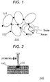
- a method for producing a multi-layer shaped object 103 according to this embodiment is shown in FIG. 2 as an example of a selective beam melting method.
- the multi-layer shaped object 103 is formed by repeating a step in which a molten portion 105 is formed by locally melting the powder for additive manufacturing 100 with a heating means 104 and then solidified.
- the powder for additive manufacturing 100 in a desired position is melted by scanning with the heating means 104 and solidified so as to be integrated with the surroundings to define the shape of the multi-layer shaped object 103.
- This series of localized melting and solidification processes is performed using an additive manufacturing device 106.
- the method for producing the multi-layer shaped object 103 according to this embodiment is shown step by step in FIG. 3 .
- an additive manufacturing step shown in FIGs. 3(a) to 3(g) in order is repeated to perform three-dimensional modeling of a multi-layer shaped object.
- the additive manufacturing step can be performed using a conventional additive manufacturing device for metal powder that has generally been used.
- a mixture (alloy powder 10) of the first metal powder 101 and the second powder 102 prepared in a powder preparation step is used as a raw material powder in the additive manufacturing step.
- the heating means of the additive manufacturing device to be used may be, for example, an appropriate means based on the principle of beam heating such as electron beam heating, laser heating, microwave heating, plasma heating, focused radiation heating, or high-frequency heating.
- the additive manufacturing device is particularly preferably based on electron beam heating or laser heating. This is because electron beam heating or laser heating makes it possible to reduce the output of a heat source, achieve a micro region where the alloy powder 10 is heated, and relatively easily control the modeling accuracy of a multi-layer structure.
- the additive manufacturing step includes a powder spreading step and a solidified layer forming step.
- a solidified tissue in a layer form (solidified layer) is formed through steps shown in FIGs. 3(a) to 3(g) in order, and the formation of a solidified tissue in a layer form (solidified layer) is repeated to form a multi-layer structure as an assembly of the solidified tissues.
- the additive manufacturing device is provided with an elevating piston having a base material-mounting stage 21 at its top end.
- a processing table 22 that is not worked with the piston is provided, and a powder feeder (not shown) that supplies the alloy powder 10 onto the processing table 22, a recoater 23 that spreads the supplied alloy powder 10, and a heating means 24 that heats the alloy powder 10 are provided.
- An air blast that removes the alloy powder 10 on the processing table 22, a temperature controller, or the like may be provided.
- the processing table 22 and these tools are housed in a chamber.
- the atmosphere in the chamber is a vacuum atmosphere or an inert gas atmosphere such as argon gas selected according to the type of the heating means 24, and the pressure or temperature of the atmosphere is monitored.
- a base material 15 is previously mounted on the base material-mounting stage 21, and the position of the base material-mounting stage 21 and the position of the processing table 22 are adjusted so that the surface (top surface) of the base material 15 on which modeling is to be performed and the top surface of the processing table 22 are flush with each other.
- the base material 15 to be used may be any appropriate material as long as the material has resistance to heat generated by the heating means 24.
- additive manufacturing of a multi-layer structure is performed on the surface of the base material 15 on which modeling is to be performed, and therefore a shaped object in which the base material 15 and the multi-layer structure are integrated with each other is obtained. Therefore, the base material 15 to be used may be one having an appropriate shape such as a flat plate shape, assuming that the base material 15 is separated from the multi-layer structure by cutting or the like.
- the base material 15 to be used may be a structural member, a mechanical member, or the like having any shape and a surface on which modeling is to be performed, assuming that the base material 15 and the multi-layer structure function in an integrated state.
- the prepared alloy powder 10 is spread on the surface on which modeling is to be performed. That is, in the first powder spreading step in additive manufacturing, the alloy powder 10 is spread on the base material 15 set in the additive manufacturing device. As shown in FIG. 3(b) , spreading of the alloy powder 10 can be performed in such a manner that the recoater 23 sweeps the surface (base material 15) on which modeling is to be performed while passing therethrough so that the alloy powder 10 supplied onto the processing table 22 by the powder feeder (not shown) (see FIG. 3(a) ) is spread in a thin layer.
- the alloy powder 10 according to this embodiment is more easily spread as compared to a case where only the first metal powder is used, because the first metal powder is mixed with the second powder that makes the first metal powder more slippery.
- the thickness of the formed thin layer of the alloy powder 10 can be appropriately adjusted according to the output of the heating means that melts the alloy powder 10 or the average particle diameter of the alloy powder 10, but is preferably in the range of about 10 ⁇ m or more but 1000 ⁇ m or less.
- the spread alloy powder 10 is melted by localized heating and then solidified, that is, a plane in which the alloy powder 10 is spread is scanned to form a solidified layer 40 in a region to be heated by localized heating.
- the formation of the solidified layer 40 (see FIG. 3(e) ) that will be described later is performed by scanning a region to be heated with the heating means 24 based on two-dimensional shape information obtained from three-dimensional shape information (e.g., 3D-CAD data) representing the three-dimensional shape of a multi-layer structure to be produced.
- three-dimensional shape information e.g., 3D-CAD data
- localized heating of the alloy powder 10 is performed by the heating means 24 only in a region to be heated on the spread alloy powder 10 so that part of the spread alloy powder 10 is selectively melted to form a minute molten pool (molten portion 20).
- the diameter of the molten portion 20 formed by melting the alloy powder 10 is preferably 1 mm or less.
- the alloy powder 10 is locally heated by moving the heating means 24 in parallel to the surface on which modeling is to be performed to scan a region to be heated.
- the scanning of a region to be heated can be performed not only by scanning with the main body of the heating means 24 but also by scanning with the irradiation spot of a heat source such as a galvanometer mirror, and is therefore performed by an appropriate system such as raster scanning.
- overlap scanning with a plurality of radiation sources may be performed to flatten the density irradiation energy.
- a solidified portion 30 formed by solidifying the molten portion 20 is integrated with the base material or the solidified portion 30 that has already been formed so that a dense assembly of the solidified portions 30 is formed.
- the scanning speed, output, energy density, and scanning width of the heating means 24 may be appropriately adjusted based on the elemental composition and particle size distribution of the alloy powder 10, the material of the base material 15, the positional relationship between the molten portion 20 and the solidified portion 30, and heat conduction or heat emission estimated from the temperature in the chamber. Further, the cooling temperature of the molten portion 20 may be set in consideration of dimension change or thermal distortion according to the elemental composition of a multi-layer structure.
- the strength distribution of a resulting multi-layer structure can be made uniform or residual stress or surface roughness of a resulting multi-layer structure can be reduced by performing scanning while maintaining the size of the molten portion 20, the rate of melting, the rate of cooling, or the interval of time between melting and cooling in their respective predetermined ranges.
- a solidified layer 40 having predetermined two dimensional shape and thickness is formed by repeating melting of the alloy powder 10 and solidification on the base material 15 mounted on the base material-mounting stage 21 to form an assembly of the solidified portions 30.
- the unmelted alloy powder 10 remaining around the solidified layer 40 or on the top surface of the solidified layer 40 may be removed by an air blast. As shown in FIG.
- the base material-mounting stage 21 is lowered by a height corresponding to the thickness of the formed solidified layer 40 to adjust the position of the base material-mounting stage 21 and the position of the processing table 22 so that the top surface of the solidified layer 40 as a new surface on which modeling is to be performed and the top surface of the processing table 22 are flush with each other.
- the powder spreading step is performed in the same manner as shown in FIGs. 3(a) and 3(b) to spread the alloy powder 10 newly supplied onto the top surface of the solidified layer 40 that has already been formed as shown in FIG. 3(g) .
- the second or more powder spreading step is performed on the powder that has already been spread or on the solidified layer.
- the spread powder or the solidified layer has larger surface irregularities than the substrate, and therefore the first metal powder having low sphericity is likely to be held by the surface irregularities.
- the first metal powder is mixed with the second powder and is therefore slippery, which makes it easy to spread the alloy powder 10 as compared to a case where only the first metal powder is spread.
- the solidified layer forming step is performed in the same manner as shown in FIGs. 3(c) to 3(e) to deposit the next solidified layer 40.
- the deposited solidified portion 30 is integrated with part of the solidified layer 40 as a lower layer and densely sintered.
- the powder spreading step and the solidified layer forming step are repeated in the same manner on the top surface of the formed solidified layer 40 as a surface on which modeling is to be performed, which makes it possible to form a multi-layer structure having desired shape and size by additive manufacturing.
- the elemental composition of each of the minute solidified tissues (solidified portions 30) well reflects the elemental composition of the alloy powder used, which makes it possible to form a solid solution phase whose elemental composition distribution and mechanical strength distribution are highly uniform.
- a solidified tissue (solidified layer 40) whose crystal growth is oriented in almost one direction can be deposited by forming solidified tissues (solidified portions 30) by heating in one direction, which makes it possible to form a multi-layer structure having high anisotropy.
- the multi-layer shaped object 103 disclosed in this embodiment is excellent in modeling accuracy because the powder for additive manufacturing 100 has improved flowability. Further, at least part of the second powder 102 is present as a fine dispersion in a metal tissue formed by melting and sintering the first metal powder 101, which makes it possible to form a shaped object excellent in high-temperature strength or fatigue strength. Such properties are suitable for various applications such as various mechanical parts, molds, and medical implants, and can contribute to improvement in the dimensional accuracy or strength of each member.
- a stainless powder formed by atomization (SUS316L powder, Höganäs Japan K.K.) was used as a first metal powder.
- the stainless powder was limited to one having a particle size distribution of 50 ⁇ m to 100 ⁇ m, and the stainless powder used had an average diameter of about 70 ⁇ m.
- Silica fine particles having an average diameter of about 0.03 ⁇ m (NIPPON AEROSIL Co., Ltd.) were used as a second powder.
- the first metal powder had an average sphericity of about 0.7
- the second powder had an average sphericity of about 0.8. It was confirmed that the second powder had an average diameter that was less than 1/10 of the average diameter of the first metal powder and excellent sphericity.
- the first metal powder and the second powder were mixed so that a volume fraction shown in Table 1 was achieved, and were then stirred with a V mixer for 1 hour to obtain a powder for additive manufacturing.
- the powder for additive manufacturing and a base material carbon steel (S45C) plate material of 100 mm ⁇ 100 mm ⁇ 10 mm
- a selective laser melting device EOS, M270
- a cylindrical multi-layer shaped object (diameter: 10 mm, height: 50 mm) was formed by repeating supply of the powder for additive manufacturing and localized melting by a heating means 104 comprising a laser, solidification, and cooling under a nitrogen atmosphere. Then, the multi-layer shaped object was cut from the base material.
- Comparative Example 1 was different from Example 1 in that the second powder was not mixed, and Comparative Examples 2 to 4 were different from Example 1 in the average diameter of the second powder and the volume fraction (mixing ratio) of the second powder.
- the other conditions were the same as those of Example 1. It is to be noted that the sphericity of silica fine particles with an average diameter of 12 ⁇ m (Denka Company Limited) used in Comparative Examples 3 and 4 was 0.9 or more that was the same as that of the silica fine particles described in Example 1.
- a copper powder formed by an electrolytic method (Höganäs Japan K.K.) was used as a first metal powder.
- the copper powder was limited to one having a particle size distribution of 50 ⁇ m to 100 ⁇ m, and the copper powder used had an average diameter of about 60 ⁇ m.
- Alumina particles having an average diameter of 0.3 ⁇ m (Denka Company Limited) were used as a second powder.
- the first metal powder had an average sphericity of about 0.4
- the second powder had an average sphericity of about 0.9. It was confirmed that the second powder had a diameter that was less than 1/10 of the diameter of the first metal powder and excellent sphericity.
- the first metal powder and the second powder were mixed so that a volume fraction shown in Table 2 was achieved, and were then stirred with a V mixer for 1 hour to obtain a powder for additive manufacturing.
- the powder for additive manufacturing and a base material carbon steel (S45C) plate material of 100 mm ⁇ 100 mm ⁇ 10 mm
- a selective laser melting device EOS, M270
- a cylindrical multi-layer shaped object (diameter: 10 mm, height: 50 mm) was formed by repeating supply of the powder for additive manufacturing and localized melting by a heating means comprising a laser, solidification, and cooling under a nitrogen atmosphere. Then, the multi-layer shaped object was cut from the base material.
- Comparative Example 5 was the same as Example 6 except that the second powder was not mixed, and Comparative Example 6 was the same as Example 6 except that the first metal powder and the second powder used in Example 6 were mixed at a mixing ratio shown in Table 1.
- Each of the multi-layer shaped objects obtained in Examples and Comparative Examples was cut along a plane including a center line, and the thus obtained cross-section was observed to determine a void ratio and the volume fraction of the second particles shown in Table 1. Assuming that the second powder was uniformly dispersed in the shaped object, the value of area fraction of the second powder in the cross-section was used as the volume fraction of the second powder. It is to be noted that in Examples 1 to 5 and Comparative Example 2, the second powder had an average diameter as small as 0.03 ⁇ m, and in Comparative Examples 3 and 4, the second powder was not uniformly dispersed, and therefore the evaluation of the volume fraction of the second powder in the multi-layer shaped object was omitted. The multi-layer shaped objects whose void ratio was restricted to less than 5% were evaluated as excellent, and the other multi-layer shaped objects were evaluated as defective.
- the powder used in each of Examples 1 to 10 had improved flowability as compared to the powder not containing the second powder used in each of Comparative Examples 1 and 5, and therefore voids in the powder before modeling were reduced.
- the void ratio of each of the multi-layer objects of Examples 1 to 10 obtained by the method according to the embodiment of the present invention could be restricted to a low value.
- the second particles were dispersed in a minute amount in the tissue of each of the materials, which is expected to have the effect of dispersion strengthening.
- the void ratio was increased under the condition where the second powder was contained at 1% or more.
- the reason for this is considered to be that the specific gravity of the second powder is lower than that of the first metal powder, and therefore when an excessive amount of the second powder is used, the second powder rises to the upper portion of the additive manufacturing powder during powder supply so that an absent portion is formed by rolling-up effect during modeling.
- Comparative Examples 3 and 4 when the diameter of the second powder was larger than 1/10 of the diameter of the first metal powder, the second powder did not uniformly enter between the particles of the first metal powder so that the void ratio was increased.
- the powder for additive manufacturing described in the embodiment according to the present invention could improve the modeling accuracy of a multi-layer structure and a fine particle dispersion effective as a reinforcing layer could be formed in the multi-layer structure.
Landscapes
- Engineering & Computer Science (AREA)
- Chemical & Material Sciences (AREA)
- Manufacturing & Machinery (AREA)
- Materials Engineering (AREA)
- Physics & Mathematics (AREA)
- Plasma & Fusion (AREA)
- Ceramic Engineering (AREA)
- Civil Engineering (AREA)
- Composite Materials (AREA)
- Structural Engineering (AREA)
- Mechanical Engineering (AREA)
- Powder Metallurgy (AREA)
Applications Claiming Priority (2)
| Application Number | Priority Date | Filing Date | Title |
|---|---|---|---|
| JP2014172169 | 2014-08-27 | ||
| PCT/JP2015/057972 WO2016031279A1 (fr) | 2014-08-27 | 2015-03-18 | Poudre pour fabrication additive couche par couche et procédé pour la production d'objet par fabrication additive couche par couche |
Publications (3)
| Publication Number | Publication Date |
|---|---|
| EP3187285A1 true EP3187285A1 (fr) | 2017-07-05 |
| EP3187285A4 EP3187285A4 (fr) | 2018-05-02 |
| EP3187285B1 EP3187285B1 (fr) | 2023-07-05 |
Family
ID=55399186
Family Applications (1)
| Application Number | Title | Priority Date | Filing Date |
|---|---|---|---|
| EP15835169.2A Active EP3187285B1 (fr) | 2014-08-27 | 2015-03-18 | Poudre pour fabrication additive couche par couche et procédé pour la production d'objet par fabrication additive couche par couche |
Country Status (3)
| Country | Link |
|---|---|
| EP (1) | EP3187285B1 (fr) |
| JP (1) | JP6303016B2 (fr) |
| WO (1) | WO2016031279A1 (fr) |
Cited By (8)
| Publication number | Priority date | Publication date | Assignee | Title |
|---|---|---|---|---|
| US10960607B2 (en) | 2018-12-13 | 2021-03-30 | General Electric Company | Systems and methods for monitoring powder spreading in additive manufacturing systems |
| DE102020000501A1 (de) | 2020-01-27 | 2021-07-29 | Eos Gmbh Electro Optical Systems | Passivierung von Filterrückständen |
| WO2021156081A1 (fr) * | 2020-02-03 | 2021-08-12 | Eos Gmbh | Procédé de modération d'une réaction de particules métalliques |
| EP3950176A4 (fr) * | 2019-06-13 | 2022-07-20 | Fukuda Metal Foil & Powder Co., Ltd. | Poudre de cuivre pour mise en forme de stratifié, corps mis en forme stratifié, procédé de fabrication de corps mis en forme stratifié, et appareil de mise en forme de stratifié |
| US11534824B2 (en) | 2018-03-15 | 2022-12-27 | Hewlett-Packard Development Company, L.P. | Composition |
| US11591857B2 (en) | 2017-05-31 | 2023-02-28 | Schlumberger Technology Corporation | Cutting tool with pre-formed hardfacing segments |
| US11786967B2 (en) | 2016-05-11 | 2023-10-17 | Proterial, Ltd. | Composite member manufacturing method and composite member |
| EP4056299A4 (fr) * | 2019-11-08 | 2023-11-15 | Daido Steel Co., Ltd. | Matériau en poudre |
Families Citing this family (6)
| Publication number | Priority date | Publication date | Assignee | Title |
|---|---|---|---|---|
| JP6766399B2 (ja) * | 2016-03-28 | 2020-10-14 | 大同特殊鋼株式会社 | 焼結用粉末および焼結体 |
| CN106925786B (zh) * | 2017-03-29 | 2019-02-19 | 西北工业大学 | 基于均匀金属液滴喷射的多粒径均匀球形粉体批量制备装置与方法 |
| WO2019038910A1 (fr) * | 2017-08-25 | 2019-02-28 | 福田金属箔粉工業株式会社 | Procédé d'évaluation de poudre de moulage de pièces en stratifié et poudre de moulage de pièces en stratifié |
| JP7395840B2 (ja) * | 2019-04-09 | 2023-12-12 | セイコーエプソン株式会社 | 積層造形用粉末および積層造形体の製造方法 |
| FR3102995B1 (fr) * | 2019-11-07 | 2022-05-13 | Commissariat Energie Atomique | Matériau en acier optimisé |
| CN114888311A (zh) * | 2022-04-18 | 2022-08-12 | 西安赛隆金属材料有限责任公司 | 一种粉床电子束增材制造装置及方法 |
Family Cites Families (4)
| Publication number | Priority date | Publication date | Assignee | Title |
|---|---|---|---|---|
| JP4947659B2 (ja) * | 2008-02-29 | 2012-06-06 | 福田金属箔粉工業株式会社 | 銅系金属粉末 |
| JP2010202928A (ja) * | 2009-03-03 | 2010-09-16 | Hyogo Prefecture | 金属造形物の製造方法及び積層造形用の金属樹脂複合体粉末 |
| JP2011021218A (ja) * | 2009-07-14 | 2011-02-03 | Kinki Univ | 積層造形用粉末材料及び粉末積層造形法 |
| JP5519338B2 (ja) * | 2010-03-04 | 2014-06-11 | 株式会社神戸製鋼所 | 粉末冶金用混合粉末及びこれを用いた焼結体の製造方法 |
-
2015
- 2015-03-18 JP JP2016544976A patent/JP6303016B2/ja active Active
- 2015-03-18 EP EP15835169.2A patent/EP3187285B1/fr active Active
- 2015-03-18 WO PCT/JP2015/057972 patent/WO2016031279A1/fr active Application Filing
Cited By (9)
| Publication number | Priority date | Publication date | Assignee | Title |
|---|---|---|---|---|
| US11786967B2 (en) | 2016-05-11 | 2023-10-17 | Proterial, Ltd. | Composite member manufacturing method and composite member |
| US11591857B2 (en) | 2017-05-31 | 2023-02-28 | Schlumberger Technology Corporation | Cutting tool with pre-formed hardfacing segments |
| US11534824B2 (en) | 2018-03-15 | 2022-12-27 | Hewlett-Packard Development Company, L.P. | Composition |
| US11684978B2 (en) | 2018-03-15 | 2023-06-27 | Hewlett-Packard Development Company, L.P. | Build material composition |
| US10960607B2 (en) | 2018-12-13 | 2021-03-30 | General Electric Company | Systems and methods for monitoring powder spreading in additive manufacturing systems |
| EP3950176A4 (fr) * | 2019-06-13 | 2022-07-20 | Fukuda Metal Foil & Powder Co., Ltd. | Poudre de cuivre pour mise en forme de stratifié, corps mis en forme stratifié, procédé de fabrication de corps mis en forme stratifié, et appareil de mise en forme de stratifié |
| EP4056299A4 (fr) * | 2019-11-08 | 2023-11-15 | Daido Steel Co., Ltd. | Matériau en poudre |
| DE102020000501A1 (de) | 2020-01-27 | 2021-07-29 | Eos Gmbh Electro Optical Systems | Passivierung von Filterrückständen |
| WO2021156081A1 (fr) * | 2020-02-03 | 2021-08-12 | Eos Gmbh | Procédé de modération d'une réaction de particules métalliques |
Also Published As
| Publication number | Publication date |
|---|---|
| JPWO2016031279A1 (ja) | 2017-04-27 |
| WO2016031279A1 (fr) | 2016-03-03 |
| JP6303016B2 (ja) | 2018-03-28 |
| EP3187285B1 (fr) | 2023-07-05 |
| EP3187285A4 (fr) | 2018-05-02 |
Similar Documents
| Publication | Publication Date | Title |
|---|---|---|
| EP3187285B1 (fr) | Poudre pour fabrication additive couche par couche et procédé pour la production d'objet par fabrication additive couche par couche | |
| US10821518B2 (en) | Additive manufacturing method and apparatus | |
| KR102048062B1 (ko) | 티탄계 분말 및 그 용제품, 소결품 | |
| JP6706608B2 (ja) | 部品の製造方法 | |
| WO2016013498A1 (fr) | Structure en alliage, et procédé de fabrication de celle-ci | |
| CN112166004B (zh) | 3d打印机用金属粉、造型物及造型物的制造方法 | |
| JP6635227B1 (ja) | 三次元形状造形物の製造方法 | |
| WO2017006610A1 (fr) | Matériau pulvérulent, article fabriqué par stratification, et procédé de fabrication d'un article par stratification | |
| JP6455699B2 (ja) | 合金構造体の製造方法 | |
| JP6455700B2 (ja) | 合金構造体の製造方法 | |
| WO2016013492A1 (fr) | Poudre d'alliage utilisée en dépôt de fil en fusion | |
| JP2007016312A (ja) | 焼結体形成方法 | |
| JP2016023365A (ja) | 合金構造体の製造方法 | |
| GB2563333A (en) | Manufacture of metal articles | |
| JP3633607B2 (ja) | 金属光造形用金属粉末とその製造方法及び金属光造形による三次元形状造形物の製造方法並びに金属光造形物 | |
| JP7401242B2 (ja) | 粉末材料 | |
| JP7336944B2 (ja) | 造形物の製造方法 | |
| JP2023012810A (ja) | 銅基粉、その製造方法、および銅基粉を用いた光造形物の製造方法 | |
| JP2020012149A (ja) | 三次元造形物の製造方法と三次元造形システム | |
| JP6443721B2 (ja) | 合金構造体の製造方法 | |
| CN108080645B (zh) | 一种降低316l不锈钢球形粉末空心率的方法 | |
| Bonesso | Fusione a Letto di Polvere di Rame e Lega CuCrZr per Soluzioni di Esaurimento di Energia | |
| JP2022551047A (ja) | 非球状粒子を含有する鉄ベースの合金粉末 | |
| JP2024054391A (ja) | 溶解原料の製造方法、および溶解原料 |
Legal Events
| Date | Code | Title | Description |
|---|---|---|---|
| STAA | Information on the status of an ep patent application or granted ep patent |
Free format text: STATUS: THE INTERNATIONAL PUBLICATION HAS BEEN MADE |
|
| PUAI | Public reference made under article 153(3) epc to a published international application that has entered the european phase |
Free format text: ORIGINAL CODE: 0009012 |
|
| STAA | Information on the status of an ep patent application or granted ep patent |
Free format text: STATUS: REQUEST FOR EXAMINATION WAS MADE |
|
| 17P | Request for examination filed |
Effective date: 20170327 |
|
| AK | Designated contracting states |
Kind code of ref document: A1 Designated state(s): AL AT BE BG CH CY CZ DE DK EE ES FI FR GB GR HR HU IE IS IT LI LT LU LV MC MK MT NL NO PL PT RO RS SE SI SK SM TR |
|
| AX | Request for extension of the european patent |
Extension state: BA ME |
|
| DAV | Request for validation of the european patent (deleted) | ||
| DAX | Request for extension of the european patent (deleted) | ||
| A4 | Supplementary search report drawn up and despatched |
Effective date: 20180405 |
|
| RIC1 | Information provided on ipc code assigned before grant |
Ipc: B22F 3/105 20060101AFI20180329BHEP Ipc: B22F 1/00 20060101ALI20180329BHEP Ipc: B33Y 70/00 20150101ALI20180329BHEP Ipc: B22F 3/16 20060101ALI20180329BHEP Ipc: B29C 67/00 20170101ALI20180329BHEP Ipc: C22C 32/00 20060101ALI20180329BHEP |
|
| STAA | Information on the status of an ep patent application or granted ep patent |
Free format text: STATUS: EXAMINATION IS IN PROGRESS |
|
| RAP1 | Party data changed (applicant data changed or rights of an application transferred) |
Owner name: HITACHI METALS, LTD. |
|
| 17Q | First examination report despatched |
Effective date: 20200403 |
|
| STAA | Information on the status of an ep patent application or granted ep patent |
Free format text: STATUS: EXAMINATION IS IN PROGRESS |
|
| REG | Reference to a national code |
Ref country code: DE Ref legal event code: R079 Ref document number: 602015084471 Country of ref document: DE Free format text: PREVIOUS MAIN CLASS: B22F0003105000 Ipc: B22F0001000000 Ref country code: DE Ref legal event code: R079 Free format text: PREVIOUS MAIN CLASS: B22F0003105000 Ipc: B22F0001000000 |
|
| GRAP | Despatch of communication of intention to grant a patent |
Free format text: ORIGINAL CODE: EPIDOSNIGR1 |
|
| STAA | Information on the status of an ep patent application or granted ep patent |
Free format text: STATUS: GRANT OF PATENT IS INTENDED |
|
| RIC1 | Information provided on ipc code assigned before grant |
Ipc: B33Y 70/10 20200101ALI20221219BHEP Ipc: B22F 10/28 20210101ALI20221219BHEP Ipc: B22F 1/052 20220101ALI20221219BHEP Ipc: B22F 3/105 20060101ALI20221219BHEP Ipc: C22C 32/00 20060101ALI20221219BHEP Ipc: B33Y 70/00 20150101ALI20221219BHEP Ipc: B29C 67/00 20170101ALI20221219BHEP Ipc: B22F 3/16 20060101ALI20221219BHEP Ipc: B22F 1/00 20060101AFI20221219BHEP |
|
| INTG | Intention to grant announced |
Effective date: 20230117 |
|
| RIN1 | Information on inventor provided before grant (corrected) |
Inventor name: SATAKE, HIROYUKI Inventor name: FUJIEDA, TADASHI Inventor name: TAKAHASHI, ISAMU Inventor name: AOTA, KINYA Inventor name: YAMAGA, KENJI Inventor name: KATO, TAKAHIKO Inventor name: KUWABARA, KOUSUKE |
|
| GRAS | Grant fee paid |
Free format text: ORIGINAL CODE: EPIDOSNIGR3 |
|
| RAP3 | Party data changed (applicant data changed or rights of an application transferred) |
Owner name: PROTERIAL, LTD. |
|
| GRAA | (expected) grant |
Free format text: ORIGINAL CODE: 0009210 |
|
| STAA | Information on the status of an ep patent application or granted ep patent |
Free format text: STATUS: THE PATENT HAS BEEN GRANTED |
|
| AK | Designated contracting states |
Kind code of ref document: B1 Designated state(s): AL AT BE BG CH CY CZ DE DK EE ES FI FR GB GR HR HU IE IS IT LI LT LU LV MC MK MT NL NO PL PT RO RS SE SI SK SM TR |
|
| REG | Reference to a national code |
Ref country code: CH Ref legal event code: EP |
|
| REG | Reference to a national code |
Ref country code: AT Ref legal event code: REF Ref document number: 1584367 Country of ref document: AT Kind code of ref document: T Effective date: 20230715 |
|
| REG | Reference to a national code |
Ref country code: DE Ref legal event code: R096 Ref document number: 602015084471 Country of ref document: DE |
|
| REG | Reference to a national code |
Ref country code: IE Ref legal event code: FG4D |
|
| REG | Reference to a national code |
Ref country code: LT Ref legal event code: MG9D |
|
| REG | Reference to a national code |
Ref country code: NL Ref legal event code: MP Effective date: 20230705 |
|
| REG | Reference to a national code |
Ref country code: AT Ref legal event code: MK05 Ref document number: 1584367 Country of ref document: AT Kind code of ref document: T Effective date: 20230705 |
|
| PG25 | Lapsed in a contracting state [announced via postgrant information from national office to epo] |
Ref country code: NL Free format text: LAPSE BECAUSE OF FAILURE TO SUBMIT A TRANSLATION OF THE DESCRIPTION OR TO PAY THE FEE WITHIN THE PRESCRIBED TIME-LIMIT Effective date: 20230705 |
|
| PG25 | Lapsed in a contracting state [announced via postgrant information from national office to epo] |
Ref country code: GR Free format text: LAPSE BECAUSE OF FAILURE TO SUBMIT A TRANSLATION OF THE DESCRIPTION OR TO PAY THE FEE WITHIN THE PRESCRIBED TIME-LIMIT Effective date: 20231006 |
|
| PG25 | Lapsed in a contracting state [announced via postgrant information from national office to epo] |
Ref country code: ES Free format text: LAPSE BECAUSE OF FAILURE TO SUBMIT A TRANSLATION OF THE DESCRIPTION OR TO PAY THE FEE WITHIN THE PRESCRIBED TIME-LIMIT Effective date: 20230705 |
|
| PG25 | Lapsed in a contracting state [announced via postgrant information from national office to epo] |
Ref country code: IS Free format text: LAPSE BECAUSE OF FAILURE TO SUBMIT A TRANSLATION OF THE DESCRIPTION OR TO PAY THE FEE WITHIN THE PRESCRIBED TIME-LIMIT Effective date: 20231105 |
|
| PG25 | Lapsed in a contracting state [announced via postgrant information from national office to epo] |
Ref country code: SE Free format text: LAPSE BECAUSE OF FAILURE TO SUBMIT A TRANSLATION OF THE DESCRIPTION OR TO PAY THE FEE WITHIN THE PRESCRIBED TIME-LIMIT Effective date: 20230705 Ref country code: RS Free format text: LAPSE BECAUSE OF FAILURE TO SUBMIT A TRANSLATION OF THE DESCRIPTION OR TO PAY THE FEE WITHIN THE PRESCRIBED TIME-LIMIT Effective date: 20230705 Ref country code: PT Free format text: LAPSE BECAUSE OF FAILURE TO SUBMIT A TRANSLATION OF THE DESCRIPTION OR TO PAY THE FEE WITHIN THE PRESCRIBED TIME-LIMIT Effective date: 20231106 Ref country code: NO Free format text: LAPSE BECAUSE OF FAILURE TO SUBMIT A TRANSLATION OF THE DESCRIPTION OR TO PAY THE FEE WITHIN THE PRESCRIBED TIME-LIMIT Effective date: 20231005 Ref country code: LV Free format text: LAPSE BECAUSE OF FAILURE TO SUBMIT A TRANSLATION OF THE DESCRIPTION OR TO PAY THE FEE WITHIN THE PRESCRIBED TIME-LIMIT Effective date: 20230705 Ref country code: LT Free format text: LAPSE BECAUSE OF FAILURE TO SUBMIT A TRANSLATION OF THE DESCRIPTION OR TO PAY THE FEE WITHIN THE PRESCRIBED TIME-LIMIT Effective date: 20230705 Ref country code: IS Free format text: LAPSE BECAUSE OF FAILURE TO SUBMIT A TRANSLATION OF THE DESCRIPTION OR TO PAY THE FEE WITHIN THE PRESCRIBED TIME-LIMIT Effective date: 20231105 Ref country code: HR Free format text: LAPSE BECAUSE OF FAILURE TO SUBMIT A TRANSLATION OF THE DESCRIPTION OR TO PAY THE FEE WITHIN THE PRESCRIBED TIME-LIMIT Effective date: 20230705 Ref country code: GR Free format text: LAPSE BECAUSE OF FAILURE TO SUBMIT A TRANSLATION OF THE DESCRIPTION OR TO PAY THE FEE WITHIN THE PRESCRIBED TIME-LIMIT Effective date: 20231006 Ref country code: FI Free format text: LAPSE BECAUSE OF FAILURE TO SUBMIT A TRANSLATION OF THE DESCRIPTION OR TO PAY THE FEE WITHIN THE PRESCRIBED TIME-LIMIT Effective date: 20230705 Ref country code: ES Free format text: LAPSE BECAUSE OF FAILURE TO SUBMIT A TRANSLATION OF THE DESCRIPTION OR TO PAY THE FEE WITHIN THE PRESCRIBED TIME-LIMIT Effective date: 20230705 Ref country code: AT Free format text: LAPSE BECAUSE OF FAILURE TO SUBMIT A TRANSLATION OF THE DESCRIPTION OR TO PAY THE FEE WITHIN THE PRESCRIBED TIME-LIMIT Effective date: 20230705 |
|
| PG25 | Lapsed in a contracting state [announced via postgrant information from national office to epo] |
Ref country code: PL Free format text: LAPSE BECAUSE OF FAILURE TO SUBMIT A TRANSLATION OF THE DESCRIPTION OR TO PAY THE FEE WITHIN THE PRESCRIBED TIME-LIMIT Effective date: 20230705 |
|
| REG | Reference to a national code |
Ref country code: DE Ref legal event code: R097 Ref document number: 602015084471 Country of ref document: DE |
|
| PG25 | Lapsed in a contracting state [announced via postgrant information from national office to epo] |
Ref country code: SM Free format text: LAPSE BECAUSE OF FAILURE TO SUBMIT A TRANSLATION OF THE DESCRIPTION OR TO PAY THE FEE WITHIN THE PRESCRIBED TIME-LIMIT Effective date: 20230705 Ref country code: RO Free format text: LAPSE BECAUSE OF FAILURE TO SUBMIT A TRANSLATION OF THE DESCRIPTION OR TO PAY THE FEE WITHIN THE PRESCRIBED TIME-LIMIT Effective date: 20230705 Ref country code: EE Free format text: LAPSE BECAUSE OF FAILURE TO SUBMIT A TRANSLATION OF THE DESCRIPTION OR TO PAY THE FEE WITHIN THE PRESCRIBED TIME-LIMIT Effective date: 20230705 Ref country code: DK Free format text: LAPSE BECAUSE OF FAILURE TO SUBMIT A TRANSLATION OF THE DESCRIPTION OR TO PAY THE FEE WITHIN THE PRESCRIBED TIME-LIMIT Effective date: 20230705 Ref country code: CZ Free format text: LAPSE BECAUSE OF FAILURE TO SUBMIT A TRANSLATION OF THE DESCRIPTION OR TO PAY THE FEE WITHIN THE PRESCRIBED TIME-LIMIT Effective date: 20230705 Ref country code: SK Free format text: LAPSE BECAUSE OF FAILURE TO SUBMIT A TRANSLATION OF THE DESCRIPTION OR TO PAY THE FEE WITHIN THE PRESCRIBED TIME-LIMIT Effective date: 20230705 |
|
| PGFP | Annual fee paid to national office [announced via postgrant information from national office to epo] |
Ref country code: DE Payment date: 20240331 Year of fee payment: 10 Ref country code: GB Payment date: 20240322 Year of fee payment: 10 |
|
| PLBE | No opposition filed within time limit |
Free format text: ORIGINAL CODE: 0009261 |
|
| STAA | Information on the status of an ep patent application or granted ep patent |
Free format text: STATUS: NO OPPOSITION FILED WITHIN TIME LIMIT |