EP3178657B1 - Dispositif d'imprimante, et procédé de détection d'état de fin proche de papier d'enregistrement de dispositif d'imprimante - Google Patents
Dispositif d'imprimante, et procédé de détection d'état de fin proche de papier d'enregistrement de dispositif d'imprimante Download PDFInfo
- Publication number
- EP3178657B1 EP3178657B1 EP15829437.1A EP15829437A EP3178657B1 EP 3178657 B1 EP3178657 B1 EP 3178657B1 EP 15829437 A EP15829437 A EP 15829437A EP 3178657 B1 EP3178657 B1 EP 3178657B1
- Authority
- EP
- European Patent Office
- Prior art keywords
- recording paper
- roll
- projection
- lid
- printer
- Prior art date
- Legal status (The legal status is an assumption and is not a legal conclusion. Google has not performed a legal analysis and makes no representation as to the accuracy of the status listed.)
- Active
Links
- 238000000034 method Methods 0.000 title claims description 8
- 238000001514 detection method Methods 0.000 claims description 23
- 238000010586 diagram Methods 0.000 description 22
- 238000005096 rolling process Methods 0.000 description 3
- 230000003287 optical effect Effects 0.000 description 2
- 230000001419 dependent effect Effects 0.000 description 1
- 230000000694 effects Effects 0.000 description 1
- 230000005484 gravity Effects 0.000 description 1
- 238000003825 pressing Methods 0.000 description 1
- 230000003252 repetitive effect Effects 0.000 description 1
- 238000004804 winding Methods 0.000 description 1
Images


Classifications
-
- B—PERFORMING OPERATIONS; TRANSPORTING
- B41—PRINTING; LINING MACHINES; TYPEWRITERS; STAMPS
- B41J—TYPEWRITERS; SELECTIVE PRINTING MECHANISMS, i.e. MECHANISMS PRINTING OTHERWISE THAN FROM A FORME; CORRECTION OF TYPOGRAPHICAL ERRORS
- B41J15/00—Devices or arrangements of selective printing mechanisms, e.g. ink-jet printers or thermal printers, specially adapted for supporting or handling copy material in continuous form, e.g. webs
- B41J15/04—Supporting, feeding, or guiding devices; Mountings for web rolls or spindles
- B41J15/044—Cassettes or cartridges containing continuous copy material, tape, for setting into printing devices
-
- B—PERFORMING OPERATIONS; TRANSPORTING
- B41—PRINTING; LINING MACHINES; TYPEWRITERS; STAMPS
- B41J—TYPEWRITERS; SELECTIVE PRINTING MECHANISMS, i.e. MECHANISMS PRINTING OTHERWISE THAN FROM A FORME; CORRECTION OF TYPOGRAPHICAL ERRORS
- B41J11/00—Devices or arrangements of selective printing mechanisms, e.g. ink-jet printers or thermal printers, for supporting or handling copy material in sheet or web form
- B41J11/0075—Low-paper indication, i.e. indicating the state when copy material has been used up nearly or completely
-
- B—PERFORMING OPERATIONS; TRANSPORTING
- B41—PRINTING; LINING MACHINES; TYPEWRITERS; STAMPS
- B41J—TYPEWRITERS; SELECTIVE PRINTING MECHANISMS, i.e. MECHANISMS PRINTING OTHERWISE THAN FROM A FORME; CORRECTION OF TYPOGRAPHICAL ERRORS
- B41J13/00—Devices or arrangements of selective printing mechanisms, e.g. ink-jet printers or thermal printers, specially adapted for supporting or handling copy material in short lengths, e.g. sheets
- B41J13/0009—Devices or arrangements of selective printing mechanisms, e.g. ink-jet printers or thermal printers, specially adapted for supporting or handling copy material in short lengths, e.g. sheets control of the transport of the copy material
-
- B—PERFORMING OPERATIONS; TRANSPORTING
- B41—PRINTING; LINING MACHINES; TYPEWRITERS; STAMPS
- B41J—TYPEWRITERS; SELECTIVE PRINTING MECHANISMS, i.e. MECHANISMS PRINTING OTHERWISE THAN FROM A FORME; CORRECTION OF TYPOGRAPHICAL ERRORS
- B41J15/00—Devices or arrangements of selective printing mechanisms, e.g. ink-jet printers or thermal printers, specially adapted for supporting or handling copy material in continuous form, e.g. webs
- B41J15/04—Supporting, feeding, or guiding devices; Mountings for web rolls or spindles
- B41J15/042—Supporting, feeding, or guiding devices; Mountings for web rolls or spindles for loading rolled-up continuous copy material into printers, e.g. for replacing a used-up paper roll; Point-of-sale printers with openable casings allowing access to the rolled-up continuous copy material
-
- B—PERFORMING OPERATIONS; TRANSPORTING
- B41—PRINTING; LINING MACHINES; TYPEWRITERS; STAMPS
- B41J—TYPEWRITERS; SELECTIVE PRINTING MECHANISMS, i.e. MECHANISMS PRINTING OTHERWISE THAN FROM A FORME; CORRECTION OF TYPOGRAPHICAL ERRORS
- B41J29/00—Details of, or accessories for, typewriters or selective printing mechanisms not otherwise provided for
- B41J29/02—Framework
-
- B—PERFORMING OPERATIONS; TRANSPORTING
- B41—PRINTING; LINING MACHINES; TYPEWRITERS; STAMPS
- B41J—TYPEWRITERS; SELECTIVE PRINTING MECHANISMS, i.e. MECHANISMS PRINTING OTHERWISE THAN FROM A FORME; CORRECTION OF TYPOGRAPHICAL ERRORS
- B41J29/00—Details of, or accessories for, typewriters or selective printing mechanisms not otherwise provided for
- B41J29/12—Guards, shields or dust excluders
- B41J29/13—Cases or covers
-
- B—PERFORMING OPERATIONS; TRANSPORTING
- B41—PRINTING; LINING MACHINES; TYPEWRITERS; STAMPS
- B41J—TYPEWRITERS; SELECTIVE PRINTING MECHANISMS, i.e. MECHANISMS PRINTING OTHERWISE THAN FROM A FORME; CORRECTION OF TYPOGRAPHICAL ERRORS
- B41J29/00—Details of, or accessories for, typewriters or selective printing mechanisms not otherwise provided for
- B41J29/46—Applications of alarms, e.g. responsive to approach of end of line
- B41J29/48—Applications of alarms, e.g. responsive to approach of end of line responsive to breakage or exhaustion of paper or approach of bottom of paper
-
- B—PERFORMING OPERATIONS; TRANSPORTING
- B65—CONVEYING; PACKING; STORING; HANDLING THIN OR FILAMENTARY MATERIAL
- B65H—HANDLING THIN OR FILAMENTARY MATERIAL, e.g. SHEETS, WEBS, CABLES
- B65H26/00—Warning or safety devices, e.g. automatic fault detectors, stop-motions, for web-advancing mechanisms
- B65H26/08—Warning or safety devices, e.g. automatic fault detectors, stop-motions, for web-advancing mechanisms responsive to a predetermined diameter
-
- B—PERFORMING OPERATIONS; TRANSPORTING
- B65—CONVEYING; PACKING; STORING; HANDLING THIN OR FILAMENTARY MATERIAL
- B65H—HANDLING THIN OR FILAMENTARY MATERIAL, e.g. SHEETS, WEBS, CABLES
- B65H16/00—Unwinding, paying-out webs
- B65H16/02—Supporting web roll
- B65H16/028—Supporting web roll on its outer circumference
-
- B—PERFORMING OPERATIONS; TRANSPORTING
- B65—CONVEYING; PACKING; STORING; HANDLING THIN OR FILAMENTARY MATERIAL
- B65H—HANDLING THIN OR FILAMENTARY MATERIAL, e.g. SHEETS, WEBS, CABLES
- B65H2301/00—Handling processes for sheets or webs
- B65H2301/40—Type of handling process
- B65H2301/41—Winding, unwinding
- B65H2301/413—Supporting web roll
- B65H2301/4137—Supporting web roll on its outer circumference
- B65H2301/41386—Supporting web roll on its outer circumference fixed or flexible frictional surface
-
- B—PERFORMING OPERATIONS; TRANSPORTING
- B65—CONVEYING; PACKING; STORING; HANDLING THIN OR FILAMENTARY MATERIAL
- B65H—HANDLING THIN OR FILAMENTARY MATERIAL, e.g. SHEETS, WEBS, CABLES
- B65H2801/00—Application field
- B65H2801/03—Image reproduction devices
- B65H2801/12—Single-function printing machines, typically table-top machines
Definitions
- the present invention relates to printers and methods of detecting the near-end state of recording paper in a printer.
- Printers that output receipts are widely used for shop registers and automated teller machines (ATMs) or cash dispensers (CDs) in banks. Such printers that output receipts perform printing on recording paper with a head while conveying the recording paper, and after conveying the recording paper to a predetermined length, cuts the recording paper to the predetermined length with a cutter.
- ATMs automated teller machines
- CDs cash dispensers
- Such printers include, for example, a printer body and a lid pivotably supported on the printer body, and a recording paper roll may be loaded in the printer body by opening the lid.
- a head is provided in the printer body, and a platen roller is provided on the lid. By closing the lid, the recording paper is held between the head and the platen roller. Printing by the thermal head is performed on the recording paper thus held between the head and the platen roller.
- the recording paper roll is loaded in a recording paper holder. While the recording paper roll is generally loaded in the recording paper holder with a shaft passing through the center opening of the recording paper, recently, drop-type printers in which recording paper is directly loaded in the recording paper holder without passing a shaft through the center opening of the recording paper in order to facilitate replenishment of recording paper are becoming popular.
- Patent Document 1 Japanese Laid-Open Patent Application No. 2009-96595
- a recording paper roll has a high degree of freedom, and therefore, may become loose and spread to affect conveyance of the recording paper while printers are in use.
- a recording paper roll is more likely to freely move inside the recording paper holder as the recording paper roll becomes smaller in diameter, thus preventing detection of a near-end state where the recording paper is near its end and is running out.
- recording paper 910 which is initially tightly rolled, may naturally become loose while being used in a drop-type printer, so that the interval between turns of the recording paper 910 may increase to form a space between turns of the recording paper 910.
- the phenomenon that the roll of recording paper 910 loosens and spreads during its use is conspicuous in particular in drop-type printers. It is inferred that this is because the recording paper 910 loaded inside the recording paper holder 920 has a high degree of freedom to be freely movable inside the recording paper holder 920 in the case of drop-type printers. That is, in the case of drop-type printers, because the recording paper 910 is allowed to roll on an internal bottom surface of the recording paper holder 920 or to vertically move through vibrations, the roll of recording paper 910 naturally loosens and spreads during its use. When the recording paper 910 loosens to spread all over inside the recording paper holder 920, the recording paper 910 cannot rotate inside the recording paper holder 920, thus affecting the conveyance of the recording paper 910.
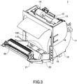
- FIG. 3 is a perspective view of the printer according to this embodiment, where a lid is open.
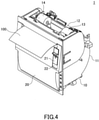
- FIG. 4 is a perspective view of the printer according to this embodiment, where the lid is closed.
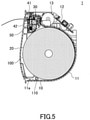
- FIG. 5 is a cross-sectional view of the printer according to this embodiment, where the lid is closed.
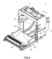
- FIG. 6 is a perspective view of the printer according to this embodiment, where the lid is open and no recording paper is accommodated.
- a printer 1 includes a printer body 10 and a lid 20 attached to the printer body 10.
- the lid 20 is attached to the printer body 10 to be pivotable on or about a shaft and openable and closable relative to the printer body 10.
- a recording paper holder 11 that accommodates a roll of recording paper 100 is provided inside the printer body 10.
- the recording paper 100 used in the printer 1 is thermal paper.
- a circuit board 12, motors 13 and 14, a thermal head 30, which is a recording head that performs printing on the recording paper 100, and a fixed blade 41 are provided in the printer body 10.
- the circuit board 12 is for controlling the printer 1.
- Each of the motors 13 and 14 is for conveying the recording paper 100 or driving the movable blade of a cutter to cut the recording paper 100.
- An open lever 21 for opening the lid 20, a movable blade 42, and a platen roller 50 are provided on the lid 20.
- the open lever 21 is provided to move upward and downward in a groove 22 provided in a surface of the lid 20.
- the fixed blade 41 provided in the printer body 10 and the movable blade 42 provided on the lid 20 form a cutter that cuts the recording paper 100.
- the movable blade 42 moves toward the fixed blade 41 to cut the recording paper 100 between the fixed blade 41 and the movable blade 42.
- the printer body 10 is provided with a lock lever 15 for detaching the platen roller 50 pressed against the thermal head 30. By pressing the lock lever 15 downward, the platen roller 50 is separated from the thermal head 30, so that the platen roller 50 can be disengaged from the printer body 10.
- a force due to the spring that is, a force exerted in a direction to push out the platen roller 50 by the spring, is applied as part of a force to open the lid 20.
- the roll of recording paper 100 is loaded inside the recording paper holder 11, and the lid 20 is closed.
- the recording paper 100 is set in the printer 1.
- the printer 1 may alternatively have the platen roller 50 provided in the printer body 10 and have the thermal head 30 provided on the lid 20.
- the lid 20 is opened when, for example, the recording paper 100 loaded in the printer body 10 runs out or is replaced.
- an interior surface of the recording paper holder 11 is formed to include a substantially flat bottom surface 11a and a curved surface 11b that is continuous with the bottom surface 11a and has a shape corresponding to the shape of the unused recording paper 100 in the initial state.
- one or more projections 110 are provided inside the recording paper holder 11 as depicted in FIGS. 3 and 6 .
- the projection 110 is provided on the interior bottom surface 11a of the recording paper holder 11, namely, a surface of the recording paper holder 11 that contacts the recording paper 100 when the roll of recording paper 100 is loaded in the recording paper holder 11, between the recording paper 100 and the lid 20 in the state of FIG. 5 .
- the projection 110 is provided at a position where the projection 110 does not contact the roll of recording paper 100 of a maximum diameter, namely, a new roll of recording paper 100 initially loaded in the recording paper holder 11, between part of the recording paper 100 that contacts the bottom surface 11a and the lid 20.
- the projection 110 is formed on the bottom surface 11a of the recording paper holder 11 at a position where the distance to the lid 20 is shorter than at least the radius of the roll of recording paper 100 in its initial state where the roll of recording paper 100 has a maximum diameter.
- the number of projections 110 provided may be one or more.
- the projections 110 may be formed to be arranged in a direction parallel to an axial direction of the recording paper 100.
- three projections 110 are formed to be parallel to an axial direction of the recording paper 100.
- one of the three projections 110 depicted in FIGS. 3 and 6 may be formed.
- the interior curved surface 11b of the recording paper holder 11 is formed to have a shape corresponding to the initial state of the recording paper 100.
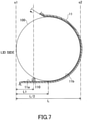
- FIGS. 7 through 11 are schematic diagrams illustrating the recording paper 100 loaded in the printer 1.
- the interior side of the lid 20 is indicated by a one-dot chain line s1
- a line tangent to the curved surface 11b at the deepest part of the interior side of the recording paper holder 11 is indicated by a one-dot chain line s2.
- a distance L between the one-dot chain lines s1 and s2 is substantially equal to or greater than the diameter of the roll of recording paper 100 in the initial state.
- the bottom of the recording paper holder 11 may be formed of the substantially flat bottom surface 11a from the midpoint between the one-dot chain lines s1 and s2 toward the one-dot chain line s1, and be formed of the curved surface 11b from the midpoint between the one-dot chain lines s1 and s2 toward the one-dot chain line s2. That is, the bottom of the recording paper holder 11 may be formed of the substantially flat bottom surface 11a from the one-dot chain line s1 side to the midpoint between the one-dot chain lines s1 and s2, at which the distance from the one-dot chain line s1 is L/2.
- the projection 110 is formed in the middle of the bottom surface 11a. Specifically, the projection 110 is positioned at a distance L1 from the one-dot chain line s1 on the bottom surface 11a.
- a new roll of the recording paper 100 is placed inside the recording paper holder 11.
- the curved surface 11b is formed to have a radius of curvature slightly greater than the radius of curvature of the recording paper 100 in the state of FIG. 7 .
- the recording paper 100 is fed while rotating inside the recording paper holder 11.
- the recording paper 100 hardly rotates to move from its initial placement position inside the recording paper holder 11 because the recording paper 100 has a shape close to the shape of the recording paper holder 11.
- the diameter of the recording paper 100 is slightly reduced compared with the state of FIG. 7 .
- the recording paper 100 is in contact with part of the bottom surface 11a or the curved surface 11b of the recording paper holder 11. Accordingly, because the diameter of the recording paper 100 is small relative to the interior size of the recording paper holder 11, the recording paper 100 may rotate to move inside the recording paper holder 11. Because the recording paper holder 11 includes the projection 110 and the curved surface 11b, however, the movement of the recording paper 100 due to rotation is limited to between the projection 110 and the curved surface 11b. Accordingly, in the state of FIG. 8 , the movement of the recording paper 100 due to rotation inside the recording paper holder 11 is reduced.
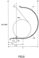
- the diameter of the recording paper 100 is further reduced compared with the state of FIG. 8 .
- the recording paper 100 is in contact with part of the bottom surface 11a or the curved surface 11b of the recording paper holder 11.
- the diameter of the recording paper 100 is small relative to the interior size of the recording paper holder 11. Therefore, it is possible for the recording paper 100 to rotate to move inside the recording paper holder 11. Because the projection 110 and the curved surface 11b are formed, however, the movement of the recording paper 100 due to rotation is limited to between the projection 110 and the curved surface 11b. Accordingly, in the state of FIG. 9 as well, the movement of the recording paper 100 due to rotation inside the recording paper holder 11 is reduced.
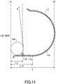
- the diameter of the recording paper 100 is further reduced compared with the state of FIG. 9 .
- the radius of the recording paper 100 is substantially equal to the distance L1. Therefore, as depicted in FIG. 10 , the recording paper 100 may be on top of the projection 110.
- the diameter of the recording paper 100 is further reduced.
- the diameter of the recording paper 100 is significantly reduced relative to the interior size of the recording paper holder 11 compared with the initial state. Therefore, it is possible for the recording paper 100 to rotate to move inside the recording paper holder 11.
- the recording paper 100 is pulled in the direction indicated by the arrow in FIG. 11 by the platen roller 50 provided on the lid 20. Therefore, the recording paper 100 moves to the lid 20 side of the projection 110. That is, the recording paper 100 is moved to the lid 20 side of the projection 110 by being pulled to the one-dot chain line s1 side on which side the lid 20 is provided.
- the recording paper 100 may contact the interior side of the lid 20. In other words, the recording paper 100 may contact the one-dot chain line s1. Accordingly, in the state of FIG. 11 , the recording paper 100 is positioned between the projection 110 and the lid 20, so that the movement of the recording paper 100 due to rotation is limited to between the projection 110 and the lid 20. Accordingly, in the state of FIG. 11 as well, the movement of the recording paper 100 due to rotation inside the recording paper holder 11 is reduced.
- the printer 1 of this embodiment by providing the projection 110 on the bottom surface 11a of the recording paper holder 11, it is possible to reduce the movement of the recording paper 100 due to rotation inside the recording paper holder 11 even when the diameter of the recording paper 100 is reduced.
- the interior curved surface 11b of the recording paper holder 11 preferably has a shape that is similar to part of the surface shape of the roll of recording paper 100.
- multiple projections that is, a first projection 211 and a second projection 212
- a first projection 211 and a second projection 212 are provided on an interior bottom surface 201a of a recording paper holder 201 of a printer as depicted in FIG. 12 .
- the first projection 211 is provided closer to the lid 20 than the second projection 212.
- the interior space of the recording paper holder 201 that accommodates the recording paper 100 is surrounded by the bottom surface 201a, a lid-side wall face 201b formed by the interior side of the lid 20, and an interior recording paper holder wall face 201c of the recording paper holder 201 that faces toward the lid side wall surface 201b.
- the interval between the lid-side wall face 201b and the recording paper holder wall face 201c is substantially equal to or greater than the diameter of the roll of recording paper 100 in the initial state.
- the interior bottom surface 201a of the recording paper holder 201 may be entirely a flat surface without including a curved surface as depicted in FIG. 12 .
- the recording paper 100 is loaded inside the recording paper holder 201.
- the recording paper 100 rotates to be fed in the direction of the arrow in FIG. 13 .
- the two projections that is, the first and second projections 211 and 212
- the movement of the recording paper 100 due to rotation is limited to between the first and second projections 211 and 212. Accordingly, in the state of FIG. 13 , the movement of the roll of recording paper 100 due to rotation inside the recording paper holder 201 is reduced.
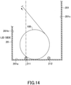
- the diameter of the recording paper 100 is reduced as depicted in FIG. 14 .
- the movement of the recording paper 100 due to rotation is still limited to between the first and second projections 211 and 212. Therefore, in the state of FIG. 14 as well, the movement of the recording paper 100 due to rotation inside the recording paper holder 201 is reduced.
- the diameter of the recording paper 100 is reduced compared with the state of FIG. 14 .
- the recording paper 100 is in contact with the first projection 211 that is closer to the lid 20 and the lid-side wall face 201b, so that the movement of the recording paper 100 due to rotation is limited to between the lid-side wall face 201b and the first projection 211. Accordingly, in the state of FIG. 15 as well, the movement of the recording paper 100 due to rotation inside the recording paper holder 201 is reduced.
- the printer of this embodiment by providing the two projections, that is, the first and second projections 211 and 212, on the interior bottom surface 201a of the recording paper holder 201, it is possible to reduce the movement of the roll of recording paper 100 due to rotation inside the recording paper holder 201 even when the recording paper 100 is used and reduced in diameter.
- the second embodiment may be the same as the first embodiment.
- FIG. 16 is a perspective view of the printer according to this embodiment, where a lid is open.
- FIG. 17 is a perspective view of the printer according to this embodiment, where the lid is closed.
- FIG. 18 is a cross-sectional view of the printer according to this embodiment, where the lid is closed.
- FIG. 19 is a diagram depicting an interior side surface of a recording paper holder of a printer body of the printer according to this embodiment.
- a printer 1000 according to this embodiment may have the same basic configuration as the printer 1 of the first embodiment.
- the printer 1000 includes the printer body 10 and the lid 20 attached to the printer body 10.
- the printer body 10 includes the recording paper holder 11.
- the control circuit board 12, the motors 13 and 14, the thermal head 30, and the fixed blade 41 are provided in the printer body 10. Furthermore, the printer body 10 is provided with the lock lever 15.
- the open lever 21, the movable blade 42, and the platen roller 50 are provided on the lid 20.
- the printer 1000 by sliding the open lever 21 provided on the lid 20 downward to press the lock lever 15, it is possible to detach the platen roller 50 from the printer body 10 and open the lid 20.
- a force due to the spring that is, a force exerted in a direction to push out the platen roller 50 by the spring, is applied as part of a force to open the lid 20.
- the roll of recording paper 100 is loaded inside the recording paper holder 11 of the printer body 10, and the lid 20 is closed.
- the roll of recording paper 100 is set in the printer 1000.
- the printer 1000 may alternatively have the platen roller 50 provided in the printer body 10 and have the thermal head 30 provided on the lid 20.
- the lid 20 is opened when, for example, the recording paper 100 loaded in the printer body 10 runs out or is replaced.
- the projection 110 is provided inside the recording paper holder 11 as depicted in FIG. 16 .
- the projection 110 is provided in the same manner as in the first embodiment.
- a first recording paper sensor 121, a second recording paper sensor 122, and a third recording paper sensor 123 are provided at positions indicated by black circles in FIG. 18 around the projection 110 inside the recording paper holder 11.
- the first through third recording paper sensors 121 through 123 may be provided on an interior side surface 11c of the recording paper holder 11 as depicted in FIG. 19 .
- the first recording paper sensor 121 is provided on the interior side surface 11c of the recording paper holder 11 between the projection 110 and the lid 20.
- the second recording paper sensor 122 is provided on the interior side surface 11c of the recording paper holder 11 at a position on a line vertical to the projection 110, for example, at a position on a straight line that is, in an axial direction of the roll of recording paper 100, substantially parallel to a vertical line passing through the center of the projection 110.
- the third recording paper sensor 123 is provided on the interior side surface 11c of the recording paper holder 11 to be positioned on the opposite side of the projection 110 from the lid 20.
- optical sensors such as reflection optical sensors are used for the first through third recording paper sensors 121 through 123
- mechanical sensors may alternatively be used.
- FIGS. 20 through 26 A method of detecting the near-end state of the recording paper 100 in a printer according to this embodiment is described with reference to FIGS. 20 through 26 .
- a region between the lid 20 (omitted in FIGS. 20 through 26 ) and the vertical line L is determined as a first region A1
- a region between the vertical line L and an interior surface of the recording paper holder 11 on the side opposite to the lid 20 side is determined as a second region A2. That is, a region on the lid 20 side (left side in FIGS.
- the first region A1 a region on the opposite side (right side in FIGS. 20 through 26 ) of the vertical line L from the lid 20 is determined as the second region A2.
- the distance from an interior wall surface of the lid 20 to the center of the projection 110 in a plane including the bottom surface 11a of the recording paper holder 11 is determined as P.
- the positional relationship between members and the like is conceptually depicted in FIGS. 20 through 26 .
- the recording paper 100 occupies substantially the entire region of the space inside the recording paper holder 11.
- a radius r1 of the recording paper 100 is greater than the distance P. Therefore, a center c1 of the recording paper 100 is positioned in the second region A2, and the recording paper 100 is in contact with the bottom surface 11a of the recording paper holder 11 in the second region A2. Therefore, the recording paper 100 is detected with the second and third recording paper sensors 122 and 123, but is not detected with the first recording paper sensor 121.
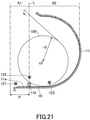
- the radius of the recording paper 100 is reduced to a radius r2 as depicted in FIG. 21 .
- the radius r2 of the recording paper 100 is still greater than the distance P. Therefore, a center c2 of the recording paper 100 is positioned in the second region A2, and the recording paper 100 is in contact with the bottom surface 11a of the recording paper holder 11 in the second region A2. Accordingly, the recording paper 100 is detected with the second and third recording paper sensors 122 and 123, but is not detected with the first recording paper sensor 121.
- the radius of the recording paper 100 is reduced to a radius r3 as depicted in FIG. 22 .
- the radius r3 of the recording paper 100 is still slightly greater than the distance P. Therefore, a center c3 of the recording paper 100 is positioned in the second region A2, and the recording paper 100 is in contact with the bottom surface 11a of the recording paper holder 11 in the second region A2. Accordingly, the recording paper 100 is detected with the second and third recording paper sensors 122 and 123, but is not detected with the first recording paper sensor 121.
- the recording paper 100 is in contact with the projection 110. Therefore, even when the recording paper 100 is pulled in the direction indicated by the arrow in FIG. 22 by the platen roller 50, it is possible to prevent the recording paper 100 from moving to the first region A1 with the projection 110.
- the radius of the recording paper 100 is reduced to a radius r4 as depicted in FIG. 23 .
- the radius r4 of the recording paper 100 is substantially equal to the distance P. Therefore, the recording paper 100 is on top of the projection 110. Therefore, a center c4 of the recording paper 100 is positioned on or near the vertical line L passing through the projection 110. Accordingly, the recording paper 100 is detected with the second recording paper sensor 122, but is not detected with the firs-c or third recording paper sensor 121 or 123.
- the recording paper 100 is pulled by the platen roller 50 provided on the lid 20. Therefore, when the radius r4 of the recording paper 100 is substantially equal to the distance P, the recording paper 100 is drawn toward the lid 20. On the other hand, the recording paper 100 touches the interior of the lid 20 to be prevented from moving leftward in FIG. 23 . Accordingly, the recording paper 100 is expected to be on top of the projection 110. Because the radius r4 of the recording paper 100 is small, however, the recording paper 100 may roll on the bottom surface 11a of the recording paper holder 11. In this case, the recording paper 100 is not detected with the first recording paper sensor 121, but may be detected with the third recording paper sensor 123 or, on rare occasions, with the second recording paper sensor 122.
- the recording paper 100 when the recording paper 100 is not detected with the first or second recording paper sensor 121 or 122 but is detected with the third recording paper sensor 123, it may be determined that the recording paper 100 is rolling on the bottom surface 11a of the recording paper holder 11 in the second region A2.
- the radius of the recording paper 100 is reduced to a radius r5 as depicted in FIG. 24 .
- the radius r5 of the recording paper 100 is smaller than the distance p, and the recording paper 100 is pulled in the direction indicated by the arrow in FIG. 24 by the platen roller 50 to be drawn toward the lid 20. Therefore, a center c5 of the recording paper 100 is positioned in the first region A1.
- the recording paper 100 is detected with the second recording paper sensor 122, but is not detected with the first or third recording paper sensor 121 or 123.
- the recording paper 100 is not detected with the first recording paper sensor 121, but may be detected with the third recording paper sensor 123 or, on rare occasions, with the second recording paper sensor 122.
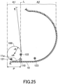
- the radius of the recording paper 100 is further reduced to a radius r6 as depicted in FIG. 25 .
- the radius r6 of the recording paper 100 is smaller than the distance P. Therefore, a center c6 of the recording paper 100 is positioned in the first region A1, and the recording paper 100 is in contact with or is about to contact the bottom surface 11a of the recording paper holder 11 in the first region A1.
- the recording paper 100 is detected with the first and second recording paper sensors 121 and 122, but is not detected with the third recording paper sensor 123.
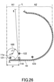
- the radius of the recording paper 100 is further reduced to a radius r7 as depicted in FIG. 26 .
- the radius r7 of the recording paper 100 is yet smaller than the distance P, and the diameter of the recording paper 100 as well is smaller than the distance P. Therefore, a center c7 of the recording paper 100 is positioned in the first region A1, and the recording paper 100 is in contact with the bottom surface 11a of the recording paper holder 11 in the first region A1.
- the recording paper 100 is detected with the first recording paper sensor 121, but is not detected with the second or third recording paper sensor 122 or 123.
- the projection 110 is provided inside the recording paper holder 11. Therefore, when the radius of the recording paper 100 is greater than the radius r6, the projection 110 restricts the movement of the recording paper 100. Therefore, the recording paper 100 is not detected with the first recording paper sensor 121. When the radius of the recording paper 100 is smaller than or equal to the radius r6, however, the recording paper 100 climbs over the projection 110 to contact the bottom surface 11a in the first region A1. Therefore, the recording paper 100 is detected with the first recording paper sensor 121. Therefore, it is possible to detect a near-end state where the recording paper 100 has run low using the first recording paper sensor 121.
- the state where the roll of recording paper 100 is further reduced to be detected with the first recording paper sensor 121 but no more detected with the second recording paper sensor 122 may be detected as a near-end state. In this state, the recording paper 100 is not detected with the third recording paper sensor 123.
- the center of the roll of recording paper 100 moves from the second region A2 to the first region A1. According to this embodiment, it is possible to determine changes in the condition of the roll of recording paper 100 becoming smaller in radius using the first through third recording paper sensors 121 through 123.
- FIG. 27 illustrates the relationship between the presence or absence of detection of the recording paper 100 with the first through third recording paper sensors 121 through 123 and the condition of the recording paper 100.
- “ 1 " indicates that the recording paper 100 is detected with the first, second or third recording paper sensor 121, 122 or 123
- "0" indicates that the recording paper 100 is not detected with the first, second or third recording paper sensor 121, 122 or 123.
- the combination of the presence or absence of detection of the recording paper 100 with the first recording paper sensor 121, the presence or absence of detection of the recording paper 100 with the second recording paper sensor 122, and the presence or absence of detection of the recording paper 100 with the third recording paper sensor 123 (hereinafter referred to as "the presence or absence of detection of the recording paper 100 with the first through third recording paper sensors 121 through 123") is (0, 1, 1).
- the presence or absence of detection of the recording paper 100 with the first through third recording paper sensors 121 through 123 is (0, 1, 0).
- the presence or absence of detection of the recording paper 100 with the first through third recording paper sensors 121 through 123 is (1, 1, 0). Therefore, the roll of recording paper 100 is not detected with the first recording paper sensor 121 before the radius becomes r6. Accordingly, the near-end state of the recording paper 100 is detected by the detection of the roll of recording paper 100 with the first recording paper sensor 121.
- the state depicted in FIG. 26 namely, the state where the radius of the recording paper 100 is r6 may be determined as the near-end state of the recording paper 100.
- the presence or absence of detection of the recording paper 100 with the first through third recording paper sensors 121 through 123 is (1, 0, 0).
- the presence or absence of detection of the recording paper 100 with the first through third recording paper sensors 121 through 123 is (0, 0, 1), it may be determined that the roll of recording paper 100 is rolling on the bottom surface 11a of the recording paper holder 11 (the recording paper 100 is rotating).
- the three recording paper sensors that is, the first through third recording paper sensors 121 through 123, do not simultaneously detect the recording paper 100. Nor do the first and third recording paper sensors 121 and 123 simultaneously detect the recording paper 100. Accordingly, when the presence or absence of detection of the recording paper 100 with the first through third recording paper sensors 121 through 123 is (1, 0, 1) or (1, 1, 1), such detection indicates a state that is impossible according to this embodiment, and is determined to be invalid.
Landscapes
- Accessory Devices And Overall Control Thereof (AREA)
- Handling Of Continuous Sheets Of Paper (AREA)
- Handling Of Sheets (AREA)
Claims (13)
- Imprimante, comprenant :
un corps d'imprimante (10) qui inclutun support de papier d'enregistrement (11) configuré pour loger un rouleau de papier d'enregistrement (100) ;un couvercle (20) fixé au corps d'imprimante (10) destiné à être ouvert et fermé par rapport au corps d'imprimante (10) ; etune saillie (110) fournie sur une surface de fond intérieure (11a) du support de papier d'enregistrement (11), la surface de fond intérieure (11a) étant plane et configurée pour toucher le papier d'enregistrement (100) lorsque le rouleau de papier d'enregistrement (100) est chargé dans le support de papier d'enregistrement (11), la saillie (110) étant fournie à une position où la saillie (110) ne touche pas le rouleau de papier d'enregistrement (100) d'un diamètre maximal, entre une partie du papier d'enregistrement (100) qui touche la surface de fond (11a) et le couvercle (20), la saillie (110) étant de plus formée sur la surface de fond (11a) du support de papier d'enregistrement (11) à une position où la distance jusqu'au couvercle (20) est plus courte qu'au moins le rayon du rouleau de papier d'enregistrement (100) dans son état initial où le rouleau de papier d'enregistrement (100) présente le diamètre maximal. - Imprimante selon la revendication 1, dans laquellele support de papier d'enregistrement (11) inclut une surface courbée (11b) formée pour être continue avec la surface de fond intérieure, etla saillie (110) est fournie entre la surface courbée (11b) et le couvercle (20).
- Imprimante selon la revendication 2, dans laquelle la surface courbée (11b) présente une forme similaire à une partie d'une forme de surface du rouleau du papier d'enregistrement (100).
- Imprimante selon la revendication 1, comprenant de plus :une tête d'enregistrement fixée à un du corps d'imprimante et du couvercle (20) ; etun rouleau de platine (50) fixé à l'autre du corps d'imprimante et du couvercle (20).
- Imprimante selon la revendication 1, dans laquelle la saillie (110) inclut une première saillie et une seconde saillie formée plus à proximité du couvercle (20) que la première saillie.
- Imprimante selon la revendication 1, dans laquelle :
un détecteur (121) est fourni entre le couvercle (20) et la saillie (110) et configuré pour détecter la présence ou l'absence du rouleau de papier d'enregistrement (100). - Imprimante selon la revendication 6, le détecteur étant un premier détecteur (121), l'imprimante comprenant de plus :
un second détecteur (122) fourni sur une ligne substantiellement verticale par rapport à la saillie (110) à l'intérieur du support de papier d'enregistrement (11), et configuré pour détecter la présence ou l'absence du rouleau de papier d'enregistrement (100). - Imprimante selon la revendication 6 ou revendication 7, comprenant de plus :
un troisième détecteur (123) fourni à une position plus distante du couvercle (20) que la saillie (110) à l'intérieur du support de papier d'enregistrement (11), et configuré pour détecter la présence ou l'absence du rouleau de papier d'enregistrement (100). - Imprimante selon l'une quelconque des revendications 1 à 4 et 6 à 8, dans laquelle :la saillie est positionnée à une distance de saillie (L1, P) à partir d'une surface de paroi intérieure du couvercle (20) dans un plan incluant la surface de fond intérieure (11a) ;le rouleau de papier d'enregistrement (100) touche la surface de fond intérieure (11a) dans une seconde région (A2) sur un côté de la saillie (110) opposé au couvercle (20) lorsque le diamètre du rouleau de papier d'enregistrement (100) se trouve dans un premier intervalle ;le rouleau de papier d'enregistrement (100) se trouve sur le haut de la saillie (110) sans toucher la surface de fond intérieure (11a) lorsque le diamètre du rouleau de papier d'enregistrement (100) se trouve dans un second intervalle inférieur au premier intervalle, et le diamètre du rouleau de papier d'enregistrement (100) est égal au double de la distance de saillie (L1, P) ; etle rouleau de papier d'enregistrement (100) touche la surface de fond intérieure (11a) dans une première région (A1) entre la saillie (110) et le couvercle (20) lorsque le diamètre du rouleau de papier d'enregistrement (100) se trouve dans un troisième intervalle inférieur au second intervalle.
- Procédé de détection d'un état proche de la fin de papier d'enregistrement dans une imprimante selon l'une quelconque des revendications 1 à 9, comprenant :la détection du rouleau de papier d'enregistrement logé à l'intérieur du support de papier d'enregistrement du corps d'imprimante de l'imprimante avec un détecteur fourni entre le couvercle et la saillie, le couvercle étant fixé au corps d'imprimante pour être ouvert et fermé par rapport au corps d'imprimante, la saillie étant fournie sur la surface de fond intérieure du support de papier d'enregistrement, la surface de fond intérieure étant plate ; etla détermination de l'état proche de la fin du rouleau de papier d'enregistrement selon une sortie du détecteur.
- Procédé selon la revendication 10, le détecteur étant un premier détecteur, le procédé comprenant de plus :la détection du rouleau de papier d'enregistrement logé à l'intérieur du support de papier d'enregistrement avec un second détecteur fourni sur une ligne substantiellement verticale par rapport à la saillie à l'intérieur du support de papier d'enregistrement ; etla détermination d'un état du rouleau de papier d'enregistrement détecté selon la sortie du premier détecteur et une sortie du second détecteur,dans lequel l'état proche de la fin du rouleau de papier d'enregistrement est déterminé en réponse à une modification de l'état de la détection du rouleau de papier d'enregistrement à partir d'un premier état où le rouleau de papier d'enregistrement est détecté avec le second détecteur dans un second état où le rouleau de papier d'enregistrement est détecté avec le premier détecteur et n'est pas détecté avec le second détecteur.
- Procédé selon la revendication 10 ou revendication 11, comprenant de plus :la détection du rouleau de papier d'enregistrement avec un troisième détecteur fourni à une position plus distante du couvercle que la saillie à l'intérieur du support de papier d'enregistrement ; etla détermination que le rouleau de papier d'enregistrement est nouvellement chargé dans le support de papier d'enregistrement en réponse à la détection du rouleau de papier d'enregistrement avec le troisième détecteur.
- Procédé selon l'une quelconque des revendications 10 à 12, dans lequel :la saillie est positionnée à une distance de saillie (L1, P) à partir d'une surface de paroi intérieure du couvercle dans un plan incluant la surface de fond intérieure ;le rouleau de papier d'enregistrement touche la surface de fond intérieure dans une seconde région (A2) sur un côté de la saillie opposé au couvercle lorsqu'un diamètre du rouleau de papier d'enregistrement se trouve dans un premier intervalle ;le rouleau de papier d'enregistrement se trouve sur le haut de la saillie sans toucher la surface de fond intérieure lorsque le diamètre du rouleau de papier d'enregistrement se trouve dans un second intervalle inférieur au premier intervalle, et le diamètre du rouleau de papier d'enregistrement est égal au double de la distance de saillie (L1, P) ; etle rouleau de papier d'enregistrement touche la surface de fond intérieure dans une première région (A1) entre la saillie et le couvercle lorsque le diamètre du rouleau de papier d'enregistrement se trouve dans un troisième intervalle inférieur au second intervalle.
Applications Claiming Priority (3)
| Application Number | Priority Date | Filing Date | Title |
|---|---|---|---|
| JP2014160774A JP6563179B2 (ja) | 2014-08-06 | 2014-08-06 | プリンタ装置及びプリンタ装置の記録紙のニアエンド検出方法 |
| JP2014177316A JP2016049737A (ja) | 2014-09-01 | 2014-09-01 | プリンタ装置 |
| PCT/JP2015/071861 WO2016021514A1 (fr) | 2014-08-06 | 2015-07-31 | Dispositif d'imprimante, et procédé de détection d'état de fin proche de papier d'enregistrement de dispositif d'imprimante |
Publications (3)
| Publication Number | Publication Date |
|---|---|
| EP3178657A1 EP3178657A1 (fr) | 2017-06-14 |
| EP3178657A4 EP3178657A4 (fr) | 2018-04-11 |
| EP3178657B1 true EP3178657B1 (fr) | 2022-01-26 |
Family
ID=55263780
Family Applications (1)
| Application Number | Title | Priority Date | Filing Date |
|---|---|---|---|
| EP15829437.1A Active EP3178657B1 (fr) | 2014-08-06 | 2015-07-31 | Dispositif d'imprimante, et procédé de détection d'état de fin proche de papier d'enregistrement de dispositif d'imprimante |
Country Status (4)
| Country | Link |
|---|---|
| US (1) | US10059133B2 (fr) |
| EP (1) | EP3178657B1 (fr) |
| CN (1) | CN106660380B (fr) |
| WO (1) | WO2016021514A1 (fr) |
Families Citing this family (1)
| Publication number | Priority date | Publication date | Assignee | Title |
|---|---|---|---|---|
| JP2022118306A (ja) * | 2021-02-02 | 2022-08-15 | 東芝テック株式会社 | 用紙収納装置 |
Family Cites Families (18)
| Publication number | Priority date | Publication date | Assignee | Title |
|---|---|---|---|---|
| JPH0328158U (fr) * | 1989-07-25 | 1991-03-20 | ||
| JPH0834554A (ja) * | 1994-07-22 | 1996-02-06 | Graphtec Corp | ロール紙残量検出方法およびその装置 |
| JPH08244261A (ja) * | 1995-03-10 | 1996-09-24 | Murata Mach Ltd | 画像記録装置 |
| EP0794064B1 (fr) * | 1996-03-06 | 2000-05-31 | Seiko Epson Corporation | Appareil de détection de fin de papier |
| JP3865072B2 (ja) | 2003-05-21 | 2007-01-10 | セイコーエプソン株式会社 | ロール紙ホルダおよび該ホルダを用いたプリンタ |
| JP4815931B2 (ja) * | 2005-08-01 | 2011-11-16 | セイコーエプソン株式会社 | 紙切断装置およびプリンタ |
| JP5068609B2 (ja) * | 2006-10-20 | 2012-11-07 | 富士通コンポーネント株式会社 | プリンタ装置 |
| JP4763577B2 (ja) * | 2006-11-06 | 2011-08-31 | セイコーインスツル株式会社 | ロール紙支持機構及びプリンタ |
| JP4974357B2 (ja) * | 2007-01-24 | 2012-07-11 | セイコーインスツル株式会社 | 連続紙処理装置 |
| JP4930247B2 (ja) * | 2007-07-26 | 2012-05-16 | ブラザー工業株式会社 | テープ印刷装置 |
| US8627754B2 (en) * | 2007-07-26 | 2014-01-14 | Brother Kogyo Kabushiki Kaisha | Sheet processing apparatus |
| JP4992657B2 (ja) | 2007-10-17 | 2012-08-08 | セイコーエプソン株式会社 | ロール紙供給装置およびロール紙プリンタ |
| JP5299782B2 (ja) * | 2009-09-30 | 2013-09-25 | ブラザー工業株式会社 | ラベル作成装置 |
| JP2012056641A (ja) * | 2010-09-03 | 2012-03-22 | Toshiba Tec Corp | ロール紙検出装置、ロール紙検出方法、及びプリンタ |
| JP2012184056A (ja) * | 2011-03-03 | 2012-09-27 | Toshiba Tec Corp | ロール紙の残量検出装置及びプリンタ |
| JP2012184054A (ja) * | 2011-03-03 | 2012-09-27 | Toshiba Tec Corp | ロール紙の残量検出装置及びプリンタ |
| US8974052B2 (en) * | 2011-08-30 | 2015-03-10 | Brother Kogyo Kabushiki Kaisha | Printer |
| JP5822661B2 (ja) * | 2011-11-07 | 2015-11-24 | 富士通コンポーネント株式会社 | 携帯型プリンタ |
-
2015
- 2015-07-31 US US15/500,166 patent/US10059133B2/en active Active
- 2015-07-31 CN CN201580041785.XA patent/CN106660380B/zh not_active Expired - Fee Related
- 2015-07-31 EP EP15829437.1A patent/EP3178657B1/fr active Active
- 2015-07-31 WO PCT/JP2015/071861 patent/WO2016021514A1/fr active Application Filing
Non-Patent Citations (1)
| Title |
|---|
| None * |
Also Published As
| Publication number | Publication date |
|---|---|
| US20170259594A1 (en) | 2017-09-14 |
| US10059133B2 (en) | 2018-08-28 |
| EP3178657A4 (fr) | 2018-04-11 |
| CN106660380A (zh) | 2017-05-10 |
| CN106660380B (zh) | 2019-06-11 |
| WO2016021514A1 (fr) | 2016-02-11 |
| EP3178657A1 (fr) | 2017-06-14 |
Similar Documents
| Publication | Publication Date | Title |
|---|---|---|
| US9724947B2 (en) | Printer | |
| US20170320340A1 (en) | Printer apparatus | |
| US9469128B2 (en) | Printing device | |
| EP2913193B1 (fr) | Imprimante | |
| EP3178657B1 (fr) | Dispositif d'imprimante, et procédé de détection d'état de fin proche de papier d'enregistrement de dispositif d'imprimante | |
| JP6082290B2 (ja) | 媒体供給装置 | |
| EP2703177B1 (fr) | Imprimante | |
| EP2927006B1 (fr) | Imprimante | |
| JP6587878B2 (ja) | プリンタ装置 | |
| JP5942665B2 (ja) | 画像処理装置 | |
| JP5626031B2 (ja) | 画像形成装置 | |
| JP2013123867A (ja) | 印刷装置 | |
| JP6563179B2 (ja) | プリンタ装置及びプリンタ装置の記録紙のニアエンド検出方法 | |
| JP5644335B2 (ja) | 画像記録装置 | |
| US20120038100A1 (en) | Sheet feeding apparatus with buffer function and method thereof | |
| JP6310807B2 (ja) | 印字装置、ページ捲り方法、及びプログラム | |
| JP2005258024A (ja) | プロセスカートリッジ及び画像形成装置 | |
| US10668756B2 (en) | Printer | |
| CN115843279A (zh) | 热敏打印机 | |
| JP2022118306A (ja) | 用紙収納装置 | |
| CN203922258U (zh) | 薄片装满检测装置、薄片装载装置及消除装置 | |
| KR100788694B1 (ko) | 경로 구획용 가이드필름이 구비된 화상형성장치 | |
| JP2012076248A (ja) | 画像記録装置 | |
| EP1291189A1 (fr) | Dispositif de tirage d'épreuves en couleur comprenant un dispositif de positionnement | |
| JP2016049737A (ja) | プリンタ装置 |
Legal Events
| Date | Code | Title | Description |
|---|---|---|---|
| STAA | Information on the status of an ep patent application or granted ep patent |
Free format text: STATUS: THE INTERNATIONAL PUBLICATION HAS BEEN MADE |
|
| PUAI | Public reference made under article 153(3) epc to a published international application that has entered the european phase |
Free format text: ORIGINAL CODE: 0009012 |
|
| STAA | Information on the status of an ep patent application or granted ep patent |
Free format text: STATUS: REQUEST FOR EXAMINATION WAS MADE |
|
| 17P | Request for examination filed |
Effective date: 20170127 |
|
| AK | Designated contracting states |
Kind code of ref document: A1 Designated state(s): AL AT BE BG CH CY CZ DE DK EE ES FI FR GB GR HR HU IE IS IT LI LT LU LV MC MK MT NL NO PL PT RO RS SE SI SK SM TR |
|
| AX | Request for extension of the european patent |
Extension state: BA ME |
|
| DAV | Request for validation of the european patent (deleted) | ||
| DAX | Request for extension of the european patent (deleted) | ||
| A4 | Supplementary search report drawn up and despatched |
Effective date: 20180308 |
|
| RIC1 | Information provided on ipc code assigned before grant |
Ipc: B41J 29/02 20060101ALI20180303BHEP Ipc: B41J 11/00 20060101ALI20180303BHEP Ipc: B65H 16/02 20060101ALI20180303BHEP Ipc: B41J 29/48 20060101ALI20180303BHEP Ipc: B41J 15/04 20060101AFI20180303BHEP |
|
| STAA | Information on the status of an ep patent application or granted ep patent |
Free format text: STATUS: EXAMINATION IS IN PROGRESS |
|
| 17Q | First examination report despatched |
Effective date: 20200227 |
|
| STAA | Information on the status of an ep patent application or granted ep patent |
Free format text: STATUS: EXAMINATION IS IN PROGRESS |
|
| GRAP | Despatch of communication of intention to grant a patent |
Free format text: ORIGINAL CODE: EPIDOSNIGR1 |
|
| STAA | Information on the status of an ep patent application or granted ep patent |
Free format text: STATUS: GRANT OF PATENT IS INTENDED |
|
| INTG | Intention to grant announced |
Effective date: 20210901 |
|
| STAA | Information on the status of an ep patent application or granted ep patent |
Free format text: STATUS: GRANT OF PATENT IS INTENDED |
|
| GRAS | Grant fee paid |
Free format text: ORIGINAL CODE: EPIDOSNIGR3 |
|
| GRAA | (expected) grant |
Free format text: ORIGINAL CODE: 0009210 |
|
| STAA | Information on the status of an ep patent application or granted ep patent |
Free format text: STATUS: THE PATENT HAS BEEN GRANTED |
|
| AK | Designated contracting states |
Kind code of ref document: B1 Designated state(s): AL AT BE BG CH CY CZ DE DK EE ES FI FR GB GR HR HU IE IS IT LI LT LU LV MC MK MT NL NO PL PT RO RS SE SI SK SM TR |
|
| REG | Reference to a national code |
Ref country code: GB Ref legal event code: FG4D |
|
| REG | Reference to a national code |
Ref country code: CH Ref legal event code: EP |
|
| REG | Reference to a national code |
Ref country code: AT Ref legal event code: REF Ref document number: 1464981 Country of ref document: AT Kind code of ref document: T Effective date: 20220215 |
|
| REG | Reference to a national code |
Ref country code: IE Ref legal event code: FG4D |
|
| REG | Reference to a national code |
Ref country code: DE Ref legal event code: R096 Ref document number: 602015076697 Country of ref document: DE |
|
| REG | Reference to a national code |
Ref country code: LT Ref legal event code: MG9D |
|
| REG | Reference to a national code |
Ref country code: NL Ref legal event code: MP Effective date: 20220126 |
|
| REG | Reference to a national code |
Ref country code: AT Ref legal event code: MK05 Ref document number: 1464981 Country of ref document: AT Kind code of ref document: T Effective date: 20220126 |
|
| PG25 | Lapsed in a contracting state [announced via postgrant information from national office to epo] |
Ref country code: NL Free format text: LAPSE BECAUSE OF FAILURE TO SUBMIT A TRANSLATION OF THE DESCRIPTION OR TO PAY THE FEE WITHIN THE PRESCRIBED TIME-LIMIT Effective date: 20220126 |
|
| PG25 | Lapsed in a contracting state [announced via postgrant information from national office to epo] |
Ref country code: SE Free format text: LAPSE BECAUSE OF FAILURE TO SUBMIT A TRANSLATION OF THE DESCRIPTION OR TO PAY THE FEE WITHIN THE PRESCRIBED TIME-LIMIT Effective date: 20220126 Ref country code: RS Free format text: LAPSE BECAUSE OF FAILURE TO SUBMIT A TRANSLATION OF THE DESCRIPTION OR TO PAY THE FEE WITHIN THE PRESCRIBED TIME-LIMIT Effective date: 20220126 Ref country code: PT Free format text: LAPSE BECAUSE OF FAILURE TO SUBMIT A TRANSLATION OF THE DESCRIPTION OR TO PAY THE FEE WITHIN THE PRESCRIBED TIME-LIMIT Effective date: 20220526 Ref country code: NO Free format text: LAPSE BECAUSE OF FAILURE TO SUBMIT A TRANSLATION OF THE DESCRIPTION OR TO PAY THE FEE WITHIN THE PRESCRIBED TIME-LIMIT Effective date: 20220426 Ref country code: LT Free format text: LAPSE BECAUSE OF FAILURE TO SUBMIT A TRANSLATION OF THE DESCRIPTION OR TO PAY THE FEE WITHIN THE PRESCRIBED TIME-LIMIT Effective date: 20220126 Ref country code: HR Free format text: LAPSE BECAUSE OF FAILURE TO SUBMIT A TRANSLATION OF THE DESCRIPTION OR TO PAY THE FEE WITHIN THE PRESCRIBED TIME-LIMIT Effective date: 20220126 Ref country code: ES Free format text: LAPSE BECAUSE OF FAILURE TO SUBMIT A TRANSLATION OF THE DESCRIPTION OR TO PAY THE FEE WITHIN THE PRESCRIBED TIME-LIMIT Effective date: 20220126 Ref country code: BG Free format text: LAPSE BECAUSE OF FAILURE TO SUBMIT A TRANSLATION OF THE DESCRIPTION OR TO PAY THE FEE WITHIN THE PRESCRIBED TIME-LIMIT Effective date: 20220426 |
|
| PG25 | Lapsed in a contracting state [announced via postgrant information from national office to epo] |
Ref country code: PL Free format text: LAPSE BECAUSE OF FAILURE TO SUBMIT A TRANSLATION OF THE DESCRIPTION OR TO PAY THE FEE WITHIN THE PRESCRIBED TIME-LIMIT Effective date: 20220126 Ref country code: LV Free format text: LAPSE BECAUSE OF FAILURE TO SUBMIT A TRANSLATION OF THE DESCRIPTION OR TO PAY THE FEE WITHIN THE PRESCRIBED TIME-LIMIT Effective date: 20220126 Ref country code: GR Free format text: LAPSE BECAUSE OF FAILURE TO SUBMIT A TRANSLATION OF THE DESCRIPTION OR TO PAY THE FEE WITHIN THE PRESCRIBED TIME-LIMIT Effective date: 20220427 Ref country code: FI Free format text: LAPSE BECAUSE OF FAILURE TO SUBMIT A TRANSLATION OF THE DESCRIPTION OR TO PAY THE FEE WITHIN THE PRESCRIBED TIME-LIMIT Effective date: 20220126 Ref country code: AT Free format text: LAPSE BECAUSE OF FAILURE TO SUBMIT A TRANSLATION OF THE DESCRIPTION OR TO PAY THE FEE WITHIN THE PRESCRIBED TIME-LIMIT Effective date: 20220126 |
|
| PG25 | Lapsed in a contracting state [announced via postgrant information from national office to epo] |
Ref country code: IS Free format text: LAPSE BECAUSE OF FAILURE TO SUBMIT A TRANSLATION OF THE DESCRIPTION OR TO PAY THE FEE WITHIN THE PRESCRIBED TIME-LIMIT Effective date: 20220526 |
|
| REG | Reference to a national code |
Ref country code: DE Ref legal event code: R097 Ref document number: 602015076697 Country of ref document: DE |
|
| PG25 | Lapsed in a contracting state [announced via postgrant information from national office to epo] |
Ref country code: SM Free format text: LAPSE BECAUSE OF FAILURE TO SUBMIT A TRANSLATION OF THE DESCRIPTION OR TO PAY THE FEE WITHIN THE PRESCRIBED TIME-LIMIT Effective date: 20220126 Ref country code: SK Free format text: LAPSE BECAUSE OF FAILURE TO SUBMIT A TRANSLATION OF THE DESCRIPTION OR TO PAY THE FEE WITHIN THE PRESCRIBED TIME-LIMIT Effective date: 20220126 Ref country code: RO Free format text: LAPSE BECAUSE OF FAILURE TO SUBMIT A TRANSLATION OF THE DESCRIPTION OR TO PAY THE FEE WITHIN THE PRESCRIBED TIME-LIMIT Effective date: 20220126 Ref country code: EE Free format text: LAPSE BECAUSE OF FAILURE TO SUBMIT A TRANSLATION OF THE DESCRIPTION OR TO PAY THE FEE WITHIN THE PRESCRIBED TIME-LIMIT Effective date: 20220126 Ref country code: DK Free format text: LAPSE BECAUSE OF FAILURE TO SUBMIT A TRANSLATION OF THE DESCRIPTION OR TO PAY THE FEE WITHIN THE PRESCRIBED TIME-LIMIT Effective date: 20220126 Ref country code: CZ Free format text: LAPSE BECAUSE OF FAILURE TO SUBMIT A TRANSLATION OF THE DESCRIPTION OR TO PAY THE FEE WITHIN THE PRESCRIBED TIME-LIMIT Effective date: 20220126 |
|
| PG25 | Lapsed in a contracting state [announced via postgrant information from national office to epo] |
Ref country code: AL Free format text: LAPSE BECAUSE OF FAILURE TO SUBMIT A TRANSLATION OF THE DESCRIPTION OR TO PAY THE FEE WITHIN THE PRESCRIBED TIME-LIMIT Effective date: 20220126 |
|
| PLBE | No opposition filed within time limit |
Free format text: ORIGINAL CODE: 0009261 |
|
| STAA | Information on the status of an ep patent application or granted ep patent |
Free format text: STATUS: NO OPPOSITION FILED WITHIN TIME LIMIT |
|
| 26N | No opposition filed |
Effective date: 20221027 |
|
| REG | Reference to a national code |
Ref country code: DE Ref legal event code: R119 Ref document number: 602015076697 Country of ref document: DE |
|
| PG25 | Lapsed in a contracting state [announced via postgrant information from national office to epo] |
Ref country code: SI Free format text: LAPSE BECAUSE OF FAILURE TO SUBMIT A TRANSLATION OF THE DESCRIPTION OR TO PAY THE FEE WITHIN THE PRESCRIBED TIME-LIMIT Effective date: 20220126 Ref country code: MC Free format text: LAPSE BECAUSE OF FAILURE TO SUBMIT A TRANSLATION OF THE DESCRIPTION OR TO PAY THE FEE WITHIN THE PRESCRIBED TIME-LIMIT Effective date: 20220126 |
|
| REG | Reference to a national code |
Ref country code: CH Ref legal event code: PL |
|
| GBPC | Gb: european patent ceased through non-payment of renewal fee |
Effective date: 20220731 |
|
| REG | Reference to a national code |
Ref country code: BE Ref legal event code: MM Effective date: 20220731 |
|
| PG25 | Lapsed in a contracting state [announced via postgrant information from national office to epo] |
Ref country code: LU Free format text: LAPSE BECAUSE OF NON-PAYMENT OF DUE FEES Effective date: 20220731 Ref country code: LI Free format text: LAPSE BECAUSE OF NON-PAYMENT OF DUE FEES Effective date: 20220731 Ref country code: FR Free format text: LAPSE BECAUSE OF NON-PAYMENT OF DUE FEES Effective date: 20220731 Ref country code: CH Free format text: LAPSE BECAUSE OF NON-PAYMENT OF DUE FEES Effective date: 20220731 |
|
| PG25 | Lapsed in a contracting state [announced via postgrant information from national office to epo] |
Ref country code: GB Free format text: LAPSE BECAUSE OF NON-PAYMENT OF DUE FEES Effective date: 20220731 Ref country code: DE Free format text: LAPSE BECAUSE OF NON-PAYMENT OF DUE FEES Effective date: 20230201 Ref country code: BE Free format text: LAPSE BECAUSE OF NON-PAYMENT OF DUE FEES Effective date: 20220731 |
|
| PG25 | Lapsed in a contracting state [announced via postgrant information from national office to epo] |
Ref country code: IT Free format text: LAPSE BECAUSE OF FAILURE TO SUBMIT A TRANSLATION OF THE DESCRIPTION OR TO PAY THE FEE WITHIN THE PRESCRIBED TIME-LIMIT Effective date: 20220126 Ref country code: IE Free format text: LAPSE BECAUSE OF NON-PAYMENT OF DUE FEES Effective date: 20220731 |
|
| PG25 | Lapsed in a contracting state [announced via postgrant information from national office to epo] |
Ref country code: HU Free format text: LAPSE BECAUSE OF FAILURE TO SUBMIT A TRANSLATION OF THE DESCRIPTION OR TO PAY THE FEE WITHIN THE PRESCRIBED TIME-LIMIT; INVALID AB INITIO Effective date: 20150731 |
|
| PG25 | Lapsed in a contracting state [announced via postgrant information from national office to epo] |
Ref country code: MK Free format text: LAPSE BECAUSE OF FAILURE TO SUBMIT A TRANSLATION OF THE DESCRIPTION OR TO PAY THE FEE WITHIN THE PRESCRIBED TIME-LIMIT Effective date: 20220126 Ref country code: CY Free format text: LAPSE BECAUSE OF FAILURE TO SUBMIT A TRANSLATION OF THE DESCRIPTION OR TO PAY THE FEE WITHIN THE PRESCRIBED TIME-LIMIT Effective date: 20220126 |