EP3173684A1 - Module d'éclairage de projecteur de véhicule automobile et projecteur associé - Google Patents
Module d'éclairage de projecteur de véhicule automobile et projecteur associé Download PDFInfo
- Publication number
- EP3173684A1 EP3173684A1 EP16200007.9A EP16200007A EP3173684A1 EP 3173684 A1 EP3173684 A1 EP 3173684A1 EP 16200007 A EP16200007 A EP 16200007A EP 3173684 A1 EP3173684 A1 EP 3173684A1
- Authority
- EP
- European Patent Office
- Prior art keywords
- air
- light source
- lighting module
- light
- ducts
- Prior art date
- Legal status (The legal status is an assumption and is not a legal conclusion. Google has not performed a legal analysis and makes no representation as to the accuracy of the status listed.)
- Granted
Links
Images
Classifications
-
- F—MECHANICAL ENGINEERING; LIGHTING; HEATING; WEAPONS; BLASTING
- F21—LIGHTING
- F21S—NON-PORTABLE LIGHTING DEVICES; SYSTEMS THEREOF; VEHICLE LIGHTING DEVICES SPECIALLY ADAPTED FOR VEHICLE EXTERIORS
- F21S41/00—Illuminating devices specially adapted for vehicle exteriors, e.g. headlamps
- F21S41/10—Illuminating devices specially adapted for vehicle exteriors, e.g. headlamps characterised by the light source
- F21S41/14—Illuminating devices specially adapted for vehicle exteriors, e.g. headlamps characterised by the light source characterised by the type of light source
- F21S41/16—Laser light sources
-
- F—MECHANICAL ENGINEERING; LIGHTING; HEATING; WEAPONS; BLASTING
- F21—LIGHTING
- F21S—NON-PORTABLE LIGHTING DEVICES; SYSTEMS THEREOF; VEHICLE LIGHTING DEVICES SPECIALLY ADAPTED FOR VEHICLE EXTERIORS
- F21S45/00—Arrangements within vehicle lighting devices specially adapted for vehicle exteriors, for purposes other than emission or distribution of light
- F21S45/40—Cooling of lighting devices
- F21S45/42—Forced cooling
- F21S45/43—Forced cooling using gas
-
- F—MECHANICAL ENGINEERING; LIGHTING; HEATING; WEAPONS; BLASTING
- F21—LIGHTING
- F21S—NON-PORTABLE LIGHTING DEVICES; SYSTEMS THEREOF; VEHICLE LIGHTING DEVICES SPECIALLY ADAPTED FOR VEHICLE EXTERIORS
- F21S41/00—Illuminating devices specially adapted for vehicle exteriors, e.g. headlamps
- F21S41/10—Illuminating devices specially adapted for vehicle exteriors, e.g. headlamps characterised by the light source
- F21S41/14—Illuminating devices specially adapted for vehicle exteriors, e.g. headlamps characterised by the light source characterised by the type of light source
-
- F—MECHANICAL ENGINEERING; LIGHTING; HEATING; WEAPONS; BLASTING
- F21—LIGHTING
- F21S—NON-PORTABLE LIGHTING DEVICES; SYSTEMS THEREOF; VEHICLE LIGHTING DEVICES SPECIALLY ADAPTED FOR VEHICLE EXTERIORS
- F21S41/00—Illuminating devices specially adapted for vehicle exteriors, e.g. headlamps
- F21S41/10—Illuminating devices specially adapted for vehicle exteriors, e.g. headlamps characterised by the light source
- F21S41/14—Illuminating devices specially adapted for vehicle exteriors, e.g. headlamps characterised by the light source characterised by the type of light source
- F21S41/176—Light sources where the light is generated by photoluminescent material spaced from a primary light generating element
-
- F—MECHANICAL ENGINEERING; LIGHTING; HEATING; WEAPONS; BLASTING
- F21—LIGHTING
- F21S—NON-PORTABLE LIGHTING DEVICES; SYSTEMS THEREOF; VEHICLE LIGHTING DEVICES SPECIALLY ADAPTED FOR VEHICLE EXTERIORS
- F21S41/00—Illuminating devices specially adapted for vehicle exteriors, e.g. headlamps
- F21S41/20—Illuminating devices specially adapted for vehicle exteriors, e.g. headlamps characterised by refractors, transparent cover plates, light guides or filters
- F21S41/25—Projection lenses
-
- F—MECHANICAL ENGINEERING; LIGHTING; HEATING; WEAPONS; BLASTING
- F21—LIGHTING
- F21S—NON-PORTABLE LIGHTING DEVICES; SYSTEMS THEREOF; VEHICLE LIGHTING DEVICES SPECIALLY ADAPTED FOR VEHICLE EXTERIORS
- F21S45/00—Arrangements within vehicle lighting devices specially adapted for vehicle exteriors, for purposes other than emission or distribution of light
- F21S45/40—Cooling of lighting devices
- F21S45/49—Attachment of the cooling means
-
- F—MECHANICAL ENGINEERING; LIGHTING; HEATING; WEAPONS; BLASTING
- F21—LIGHTING
- F21V—FUNCTIONAL FEATURES OR DETAILS OF LIGHTING DEVICES OR SYSTEMS THEREOF; STRUCTURAL COMBINATIONS OF LIGHTING DEVICES WITH OTHER ARTICLES, NOT OTHERWISE PROVIDED FOR
- F21V29/00—Protecting lighting devices from thermal damage; Cooling or heating arrangements specially adapted for lighting devices or systems
- F21V29/50—Cooling arrangements
- F21V29/502—Cooling arrangements characterised by the adaptation for cooling of specific components
-
- F—MECHANICAL ENGINEERING; LIGHTING; HEATING; WEAPONS; BLASTING
- F21—LIGHTING
- F21V—FUNCTIONAL FEATURES OR DETAILS OF LIGHTING DEVICES OR SYSTEMS THEREOF; STRUCTURAL COMBINATIONS OF LIGHTING DEVICES WITH OTHER ARTICLES, NOT OTHERWISE PROVIDED FOR
- F21V29/00—Protecting lighting devices from thermal damage; Cooling or heating arrangements specially adapted for lighting devices or systems
- F21V29/50—Cooling arrangements
- F21V29/60—Cooling arrangements characterised by the use of a forced flow of gas, e.g. air
- F21V29/67—Cooling arrangements characterised by the use of a forced flow of gas, e.g. air characterised by the arrangement of fans
-
- F—MECHANICAL ENGINEERING; LIGHTING; HEATING; WEAPONS; BLASTING
- F21—LIGHTING
- F21V—FUNCTIONAL FEATURES OR DETAILS OF LIGHTING DEVICES OR SYSTEMS THEREOF; STRUCTURAL COMBINATIONS OF LIGHTING DEVICES WITH OTHER ARTICLES, NOT OTHERWISE PROVIDED FOR
- F21V29/00—Protecting lighting devices from thermal damage; Cooling or heating arrangements specially adapted for lighting devices or systems
- F21V29/50—Cooling arrangements
- F21V29/60—Cooling arrangements characterised by the use of a forced flow of gas, e.g. air
- F21V29/67—Cooling arrangements characterised by the use of a forced flow of gas, e.g. air characterised by the arrangement of fans
- F21V29/673—Cooling arrangements characterised by the use of a forced flow of gas, e.g. air characterised by the arrangement of fans the fans being used for intake
-
- F—MECHANICAL ENGINEERING; LIGHTING; HEATING; WEAPONS; BLASTING
- F21—LIGHTING
- F21V—FUNCTIONAL FEATURES OR DETAILS OF LIGHTING DEVICES OR SYSTEMS THEREOF; STRUCTURAL COMBINATIONS OF LIGHTING DEVICES WITH OTHER ARTICLES, NOT OTHERWISE PROVIDED FOR
- F21V29/00—Protecting lighting devices from thermal damage; Cooling or heating arrangements specially adapted for lighting devices or systems
- F21V29/50—Cooling arrangements
- F21V29/70—Cooling arrangements characterised by passive heat-dissipating elements, e.g. heat-sinks
- F21V29/74—Cooling arrangements characterised by passive heat-dissipating elements, e.g. heat-sinks with fins or blades
- F21V29/76—Cooling arrangements characterised by passive heat-dissipating elements, e.g. heat-sinks with fins or blades with essentially identical parallel planar fins or blades, e.g. with comb-like cross-section
- F21V29/763—Cooling arrangements characterised by passive heat-dissipating elements, e.g. heat-sinks with fins or blades with essentially identical parallel planar fins or blades, e.g. with comb-like cross-section the planes containing the fins or blades having the direction of the light emitting axis
-
- F—MECHANICAL ENGINEERING; LIGHTING; HEATING; WEAPONS; BLASTING
- F21—LIGHTING
- F21V—FUNCTIONAL FEATURES OR DETAILS OF LIGHTING DEVICES OR SYSTEMS THEREOF; STRUCTURAL COMBINATIONS OF LIGHTING DEVICES WITH OTHER ARTICLES, NOT OTHERWISE PROVIDED FOR
- F21V29/00—Protecting lighting devices from thermal damage; Cooling or heating arrangements specially adapted for lighting devices or systems
- F21V29/50—Cooling arrangements
- F21V29/70—Cooling arrangements characterised by passive heat-dissipating elements, e.g. heat-sinks
- F21V29/83—Cooling arrangements characterised by passive heat-dissipating elements, e.g. heat-sinks the elements having apertures, ducts or channels, e.g. heat radiation holes
-
- F—MECHANICAL ENGINEERING; LIGHTING; HEATING; WEAPONS; BLASTING
- F21—LIGHTING
- F21S—NON-PORTABLE LIGHTING DEVICES; SYSTEMS THEREOF; VEHICLE LIGHTING DEVICES SPECIALLY ADAPTED FOR VEHICLE EXTERIORS
- F21S41/00—Illuminating devices specially adapted for vehicle exteriors, e.g. headlamps
- F21S41/10—Illuminating devices specially adapted for vehicle exteriors, e.g. headlamps characterised by the light source
- F21S41/19—Attachment of light sources or lamp holders
-
- F—MECHANICAL ENGINEERING; LIGHTING; HEATING; WEAPONS; BLASTING
- F21—LIGHTING
- F21S—NON-PORTABLE LIGHTING DEVICES; SYSTEMS THEREOF; VEHICLE LIGHTING DEVICES SPECIALLY ADAPTED FOR VEHICLE EXTERIORS
- F21S41/00—Illuminating devices specially adapted for vehicle exteriors, e.g. headlamps
- F21S41/20—Illuminating devices specially adapted for vehicle exteriors, e.g. headlamps characterised by refractors, transparent cover plates, light guides or filters
- F21S41/29—Attachment thereof
-
- F—MECHANICAL ENGINEERING; LIGHTING; HEATING; WEAPONS; BLASTING
- F21—LIGHTING
- F21W—INDEXING SCHEME ASSOCIATED WITH SUBCLASSES F21K, F21L, F21S and F21V, RELATING TO USES OR APPLICATIONS OF LIGHTING DEVICES OR SYSTEMS
- F21W2102/00—Exterior vehicle lighting devices for illuminating purposes
-
- F—MECHANICAL ENGINEERING; LIGHTING; HEATING; WEAPONS; BLASTING
- F21—LIGHTING
- F21W—INDEXING SCHEME ASSOCIATED WITH SUBCLASSES F21K, F21L, F21S and F21V, RELATING TO USES OR APPLICATIONS OF LIGHTING DEVICES OR SYSTEMS
- F21W2107/00—Use or application of lighting devices on or in particular types of vehicles
- F21W2107/10—Use or application of lighting devices on or in particular types of vehicles for land vehicles
-
- F—MECHANICAL ENGINEERING; LIGHTING; HEATING; WEAPONS; BLASTING
- F21—LIGHTING
- F21Y—INDEXING SCHEME ASSOCIATED WITH SUBCLASSES F21K, F21L, F21S and F21V, RELATING TO THE FORM OR THE KIND OF THE LIGHT SOURCES OR OF THE COLOUR OF THE LIGHT EMITTED
- F21Y2115/00—Light-generating elements of semiconductor light sources
- F21Y2115/30—Semiconductor lasers
Definitions
- the present invention relates to a motor vehicle headlamp lighting module, of the type comprising: at least one first light source; a device for converting the wavelength of the light emitted by said first light source; and a fan adapted to generate an air flow.
- Adaptive fire devices make it possible to adjust the intensity, the dimensions and / or the direction of the beams according to the traffic conditions, in order to fulfill these various functions.
- Each projector generally comprises several lighting modules that make it possible to form a light beam of the projector.
- the modules can be switched on or off independently of each other to vary the beam characteristics in real time.
- lighting module is meant an assembly containing at least one light source and an optical projection or reflection system.
- Lighting modules include in particular light devices comprising light sources of the laser diode type, emitting in blue light, and a device adapted to convert the laser radiation into a white light beam.
- a conversion device consists for example of phosphor elements.
- the light sources and the conversion device generate a significant heat in operation, it is necessary to cool them. It is in particular known to equip the lighting modules with fans that generate a flow of air capable of convection cooling the heating elements.
- the present invention aims to propose an improvement of existing lighting modules, optimizing in particular the cooling efficiency of the various elements emitting heat.
- the present invention relates to a lighting module of the aforementioned type, comprising at least a first and a second separate air ducts, the fan being placed at the inlet of each of said first and second air ducts. so as to distribute the air flow between said ducts, the first light source and the wavelength conversion device being respectively disposed at the outlet of the first and second air ducts.
- the invention further relates to a motor vehicle headlamp, comprising at least one lighting module as described above.
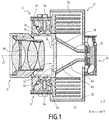
- the figure 1 represents in section a lighting module 10 according to a first embodiment of the invention.
- the lighting module 10 is intended to be incorporated in a motor vehicle headlamp, said headlamp optionally comprising one or more other lighting modules.
- the lighting module 10 comprises a first 12 and a second 14 light devices, a device 16 for converting wavelength and an optical imaging system 18.
- the module 10 further comprises a fan 20, able to generate an air flow.
- the module 10 further comprises a support 22 to which are attached the first 12 and second 14 light devices, the conversion device 16, the optical system 18 and the fan 20.
- first 12 and second 14 light devices are substantially identical and correspond to the same description below.
- the light device 12, 14 comprises a light source 24 disposed along an emission axis substantially parallel to X.
- the light source 24 is a semiconductor light source, more preferably a laser diode.
- the light source 24 of each of the light devices 12, 14 is a laser diode.
- the laser diode 24 emits for example a visible beam whose wavelength is between 400 nm and 500 nm, preferably between 440 nm and 470 nm.
- the light device 12, 14 further comprises an optical device capable of concentrating the beam emitted by the laser diode 24.
- the light device 12, 14 further comprises a reflector 26 adapted to send to the conversion device 16 a light beam emitted by the laser diode 24 and concentrated by the optical device.
- the reflector 26 is movable in one or two directions, so as to form a scanning system.
- the reflector 26 is formed of several movable mirrors independently. The displacement of the mirrors of the reflector is notably controlled by an electronic card 28.
- the light device 12, 14 further comprises: an envelope 30, enclosing the diode 24, the optical device and the reflector 26; and a heat exchanger 32, assembled to the diode 24.
- the heat exchanger 32 is preferably a finned radiator made of a material with good thermal conductivity such as aluminum.
- the envelope 30 has a lateral orifice 34 allowing the output of the light beam emitted by the diode 24 and deflected by the reflector 26, to the wavelength conversion device 16.
- the wavelength conversion device 16 is for example formed of a plate 36 of a reflective substrate for the laser radiation, on which is deposited a continuous and homogeneous layer 38 of phosphor.
- the plate 36 is for example made of aluminum.
- the phosphor layer 38 is disposed in a plane (Y, Z).
- the first 12 and second 14 light devices are respectively arranged above and below, along Z, of said layer 38.
- the plane (Y, Z) of the layer 38 is close to a focal plane of the optical system 18.
- Said optical system 18 comprises, for example, one or more lenses 40.
- the support 22 of the lighting module 10 comprises two distinct elements, more specifically a plate 42 and a housing 44.
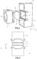
- the plate 42, the housing 44 and the wavelength conversion device 16 are represented in exploded perspective at the figure 2 .
- the housing 44 is shown from the back to the figure 3 .
- the plate 42 and the housing 44 are assembled to each other, for example by screwing.
- the plate 36 of the device 16 is held between the plate 42 and the housing 44 along the axis 23, the phosphor layer 38 being oriented towards the plate 42.
- the plate 42 has a substantially parallelepipedal shape with walls respectively arranged in planes (X, Y), (X, Z) and (Y, Z).
- the plate 42 comprises in particular a front opening 48 and a rear opening 50, respectively formed in each of the two walls arranged along (Y, Z).
- the plate 42 is assembled to the optical system 18 at the front opening 48.
- the plate 42 is further assembled to the plate 36 of the wavelength conversion device 16 at the rear opening 50.
- the plate 42 also has an upper opening 52 and a lower opening 54, respectively formed in each of the two walls arranged along (X, Y).
- the plate 42 is connected to each of the first 12 and second 14 luminous devices, respectively at the upper opening 52 and the lower opening 54.
- Each of the upper 52 and lower 54 openings is disposed opposite the the lateral orifice 34 of the envelope 30 of the light device 12, 14.
- the housing 44 also has a substantially parallelepiped shape.
- the housing 44 comprises in particular a bottom 60 disposed along (Y, Z), and lateral outer walls respectively arranged along (X, Y) and (X, Z).
- the housing 44 has two internal walls 62, 64, disposed on either side of a plane of symmetry (X, Y) of said housing, said plane of symmetry passing through the optical axis 23.
- the inner walls 62, 64 rest on the lateral outer walls arranged along (X, Z) of the housing 44.
- the internal walls 62, 64 divide the inside of the housing 44 into three separate ducts 66, 68 and 70, isolated from each other and contiguous along Z.
- the housing 44 comprises a central duct 68 and two lateral ducts 66 and 70.
- the bottom 60 of the housing 44 has three openings 72, 74 and 76, contiguous to Z. Each of said openings forms an inlet of a duct, respectively 66, 68 and 70.
- the fan 20 is assembled at the bottom 60 so as to cover the openings 72, 74 and 76. Thus, an air flow generated by the fan 20 is distributed between the three separate ducts 66, 68 and 70.
- the radiator 32 of each of the light devices 12, 14 is disposed inside the housing 44, in one of the two lateral ducts 66 and 70. Thus, an air flow passing through each lateral duct is able to cool a diode 24 via the corresponding radiator 32.
- the plate 36 of the conversion device 16 of wavelength conversion is disposed at the outlet of the central duct 68, in contact with the edges of the inner walls 62, 64, opposite to the opening 74.
- the casing 44 comprises holes 80 near the plate 36, to form an air outlet of the central duct 68.
- the position of the inner walls 62, 64 is configured so as to direct on the plate 36 of the conversion device 16 a fraction of between 10% and 40%, preferably between 15% and 25%, of the air flow generated by the fan 20.
- Each radiator 32 thus receives between 30% and 45% of said air flow rate.
- each of the diodes 24 When each of the diodes 24 is supplied with electricity, it emits laser radiation which is sent to the conversion device 16 by the reflector 26 which forms a scanning system. Several points of the phosphor layer 38 thus successively receive the laser radiation of the diode 24.
- each point of the layer 38 receiving monochromatic and coherent "blue” laser radiation, reemits a light considered as "white", that is to say having a plurality of wavelengths between 400 nm and about 800 nm.
- the optical imaging system 18 then forms at infinity an image of the light spots of the phosphor layer 38, in the form of a light beam able to illuminate the road ahead of a vehicle.
- the wavelength conversion process causes heating of the plate 36 of the conversion device 16. Moreover, the heat diffused by each diode 24 is dissipated in the corresponding radiator 32.
- the fan 20 generates a flow of air distributed in three separate streams in each of the ducts 66, 68 and 70. Each of said air flows cools the plate 36 or one of the radiators 32, avoiding overheating of the module 10.
- the shape of the housing 44 allows the formation in parallel of three separate air flows from a single fan 20. It is thus possible to modulate the amount of air directed on each of the elements of the module 10 may heat up. during operation.
Landscapes
- Engineering & Computer Science (AREA)
- General Engineering & Computer Science (AREA)
- Physics & Mathematics (AREA)
- Optics & Photonics (AREA)
- Non-Portable Lighting Devices Or Systems Thereof (AREA)
- Lighting Device Outwards From Vehicle And Optical Signal (AREA)
Abstract
Description
- La présente invention concerne un module d'éclairage de projecteur de véhicule automobile, du type comprenant : au moins une première source lumineuse ; un dispositif de conversion de longueur d'onde de la lumière émise par ladite première source lumineuse ; et un ventilateur apte à générer un débit d'air.
- Il est connu de prévoir, à l'avant d'un véhicule automobile, des projecteurs aptes à former des faisceaux lumineux pour remplir différentes fonctions d'éclairage, par exemple de type « feux de route » ou « feux de croisement ».
- Des dispositifs de feux, dits adaptatifs, permettent d'ajuster l'intensité, les dimensions et/ou la direction des faisceaux selon les conditions de circulation, afin de remplir ces différentes fonctions.
- Chaque projecteur comporte en général plusieurs modules d'éclairage qui permettent de former un faisceau lumineux du projecteur. Les modules peuvent être allumés ou éteints indépendamment les uns des autres pour faire varier en temps réel les caractéristiques du faisceau.
- On entend par module d'éclairage un ensemble contenant au moins une source lumineuse et un système optique de projection ou de réflexion.
- Des modules d'éclairage, tels que décrits dans le document
EP2690352 au nom de la Demanderesse, comprennent notamment des dispositifs lumineux comportant des sources lumineuses de type diodes laser, émettant en lumière bleue, ainsi qu'un dispositif apte à convertir le rayonnement laser en un faisceau de lumière blanche. Un tel dispositif de conversion est par exemple constitué d'éléments de luminophore. - Les sources lumineuses et le dispositif de conversion générant une chaleur importante en fonctionnement, il est nécessaire de les refroidir. Il est notamment connu d'équiper les modules d'éclairage de ventilateurs qui génèrent un flux d'air apte à refroidir par convection les éléments chauffants.
- La présence d'un ventilateur pour chacun des éléments précités permet un refroidissement optimal. Cette solution est cependant coûteuse.
- La présente invention a pour but de proposer une amélioration des modules d'éclairage existants, en optimisant notamment l'efficacité du refroidissement des différents éléments émettant de la chaleur.
- A cet effet, la présente invention se rapporte à un module d'éclairage du type précité, comportant au moins un premier et un deuxième conduits d'air distincts, le ventilateur étant placé en entrée de chacun desdits premier et deuxième conduits d'air de sorte à répartir le débit d'air entre lesdits conduits, la première source lumineuse et le dispositif de conversion de longueur d'onde étant respectivement disposés en sortie du premier et du deuxième conduits d'air.
- Suivant d'autres aspects avantageux de l'invention, le module d'éclairage comporte l'une ou plusieurs des caractéristiques suivantes, prises isolément ou suivant toutes les combinaisons techniquement possibles :
- le module d'éclairage comporte au moins une deuxième source lumineuse, le dispositif de conversion étant apte à recevoir la lumière émise par ladite deuxième source lumineuse, ledit module d'éclairage comportant au moins un troisième conduit d'air distinct des premier et deuxième conduits d'air, le ventilateur étant placé en entrée dudit troisième conduit d'air de sorte à répartir le débit d'air entre lesdits conduits, la deuxième source lumineuse étant disposée en sortie dudit troisième conduit d'air ;
- le module d'éclairage comporte un support auquel sont fixés le ventilateur, le dispositif de conversion de longueur d'onde, la première et éventuellement la deuxième source(s) lumineuse(s), ledit support comprenant une ou des paroi(s) interne(s) définissant les conduits d'air ;
- les conduits d'air sont configurés de sorte à diriger sur le dispositif de conversion de longueur d'onde une fraction comprise entre 10% et 40%, préférentiellement entre 15% et 25%, du débit d'air généré par le ventilateur ;
- au moins la première source lumineuse est au contact d'un radiateur apte à échanger de la chaleur avec un flux d'air, ledit radiateur étant disposé dans le conduit d'air correspondant à ladite source lumineuse ;
- au moins la première source lumineuse est une source lumineuse à semi-conducteurs, de préférence une diode laser, émettant un rayonnement dont la longueur d'onde est préférentiellement comprise entre 400 nm et 500 nm ;
- le dispositif de conversion de longueur d'onde comporte une plaque réfléchissante au rayonnement laser et une couche de luminophore recouvrant ladite plaque ;
- le module d'éclairage comporte en outre au moins un dispositif réflecteur apte à dévier la lumière émise par au moins la première source lumineuse et à renvoyer ladite lumière sur le dispositif de conversion de longueur d'onde ;
- le module d'éclairage comporte en outre un système optique d'imagerie apte à projeter la lumière réémise par le dispositif de conversion de longueur d'onde.
- L'invention se rapporte en outre à un projecteur de véhicule automobile, comprenant au moins un module d'éclairage tel que décrit ci-dessus.
- L'invention sera mieux comprise à la lecture de la description qui va suivre, donnée uniquement à titre d'exemple non limitatif et faite en se référant aux dessins sur lesquels :
- la
figure 1 est une vue en coupe d'un module d'éclairage selon un mode de réalisation de l'invention ; - la
figure 2 est une vue en perspective éclatée d'éléments du module d'éclairage de lafigure 1 ; et - la
figure 3 est une vue de dos d'un élément du module d'éclairage de lafigure 1 . - La
figure 1 représente en coupe un module d'éclairage 10 selon un premier mode de réalisation de l'invention. - Le module d'éclairage 10 est destiné à être incorporé dans un projecteur de véhicule automobile, ledit projecteur comprenant éventuellement un ou plusieurs autres modules d'éclairage.
- Le module d'éclairage 10 comporte un premier 12 et un second 14 dispositifs lumineux, un dispositif 16 de conversion de longueur d'onde et un système optique 18 d'imagerie.
- Le module 10 comporte en outre un ventilateur 20, apte à générer un débit d'air.
- Le module 10 comporte en outre un support 22 auquel sont fixés les premier 12 et second 14 dispositifs lumineux, le dispositif de conversion 16, le système optique 18 et le ventilateur 20.
- On considère une base orthonormée (X, Y, Z) représentée aux
figures 1 ,2 et 3 . Les axes horizontaux X et Y sont respectivement parallèle et perpendiculaire à un axe optique 23 du système optique 18 ; l'axe Z est vertical. - Dans l'exemple de la
figure 1 , les premier 12 et second 14 dispositifs lumineux sont sensiblement identiques et correspondent à la même description ci-dessous. - Le dispositif lumineux 12, 14 comporte une source lumineuse 24 disposée selon un axe d'émission sensiblement parallèle à X. Préférentiellement, la source lumineuse 24 est une source lumineuse à semi-conducteurs, plus préférentiellement une diode laser. Dans l'exemple de la
figure 1 , la source lumineuse 24 de chacun des dispositifs lumineux 12, 14 est une diode laser. - La diode laser 24 émet par exemple un faisceau visible dont la longueur d'onde est comprise entre 400 nm et 500 nm, de préférence comprise entre 440 nm et 470 nm.
- Le dispositif lumineux 12, 14 comporte en outre un dispositif optique apte à concentrer le faisceau émis par la diode laser 24.
- Le dispositif lumineux 12, 14 comporte en outre un réflecteur 26 apte à envoyer vers le dispositif de conversion 16 un rayon lumineux émis par la diode laser 24 et concentré par le dispositif optique. De préférence, le réflecteur 26 est mobile selon une ou deux directions, de sorte à former un système de balayage. Dans l'exemple de la
figure 1 , le réflecteur 26 est formé de plusieurs miroirs mobiles de manière indépendante. Le déplacement des miroirs du réflecteur est notamment contrôlé par une carte électronique 28. - Le dispositif lumineux 12, 14 comporte en outre : une enveloppe 30, renfermant la diode 24, le dispositif optique et le réflecteur 26 ; et un échangeur de chaleur 32, assemblé à la diode 24. L'échangeur de chaleur 32 est préférentiellement un radiateur à ailettes réalisé dans un matériau à bonne conductivité thermique tel que l'aluminium.
- L'enveloppe 30 comporte un orifice latéral 34 permettant la sortie du rayon lumineux émis par la diode 24 et dévié par le réflecteur 26, vers le dispositif 16 de conversion de longueur d'onde.
- Le dispositif 16 de conversion de longueur d'onde est par exemple formé d'une plaque 36 d'un substrat réfléchissant pour le rayonnement laser, sur lequel est déposée une couche continue et homogène 38 de luminophore. La plaque 36 est par exemple réalisée en aluminium.
- La couche 38 de luminophore est disposée dans un plan (Y, Z). Les premier 12 et second 14 dispositifs lumineux sont respectivement disposés au-dessus et au-dessous, selon Z, de ladite couche 38.
- Le plan (Y, Z) de la couche 38 est proche d'un plan focal du système optique 18. Ledit système optique 18 comprend par exemple une ou plusieurs lentilles 40.
- Dans l'exemple de la
figure 1 , le support 22 du module d'éclairage 10 comporte deux éléments distincts, plus précisément une platine 42 et un boîtier 44. La platine 42, le boîtier 44 et le dispositif 16 de conversion de longueur d'onde sont représentés en perspective éclatée à lafigure 2 . Le boîtier 44 est représenté de dos à lafigure 3 . - La platine 42 et le boîtier 44 sont assemblés l'un à l'autre, par exemple par vissage. La plaque 36 du dispositif 16 est maintenue entre la platine 42 et le boîtier 44 selon l'axe 23, la couche 38 de luminophore étant orientée vers la platine 42.
- La platine 42 a une forme sensiblement parallélépipédique avec des parois respectivement disposées selon des plans (X, Y), (X, Z) et (Y, Z).
- La platine 42 comporte notamment une ouverture avant 48 et une ouverture arrière 50, respectivement ménagées dans chacune des deux parois disposées selon (Y, Z). La platine 42 est assemblée au système optique 18 au niveau de l'ouverture avant 48. La platine 42 est en outre assemblée à la plaque 36 du dispositif 16 de conversion de longueur d'onde, au niveau de l'ouverture arrière 50.
- La platine 42 comporte également une ouverture supérieure 52 et une ouverture inférieure 54, respectivement ménagées dans chacune des deux parois disposées selon (X, Y). La platine 42 est assemblée à chacun des premier 12 et second 14 dispositifs lumineux, au niveau respectivement de l'ouverture supérieure 52 et de l'ouverture inférieure 54. Chacune des ouvertures supérieure 52 et inférieure 54 est disposée en vis-à-vis de l'orifice latéral 34 de l'enveloppe 30 du dispositif lumineux 12, 14.
- Le boîtier 44 a également une forme sensiblement parallélépipédique. Le boîtier 44 comporte notamment un fond 60, disposé selon (Y, Z), et des parois externes latérales respectivement disposées selon (X, Y) et (X, Z).
- Par ailleurs, le boîtier 44 comporte deux parois internes 62, 64, disposées de part et d'autre d'un plan de symétrie (X, Y) dudit boîtier, ledit plan de symétrie passant par l'axe optique 23. Les parois internes 62, 64 s'appuient sur les parois externes latérales disposées selon (X, Z) du boîtier 44.
- Les parois internes 62, 64 divisent l'intérieur du boîtier 44 en trois conduits distincts 66, 68 et 70, isolés les uns des autres et contigus selon Z. En particulier, le boîtier 44 comporte un conduit central 68 et deux conduits latéraux 66 et 70.
- Le fond 60 du boîtier 44 comporte trois ouvertures 72, 74 et 76, contiguës selon Z. Chacune desdites ouvertures forme une entrée d'un conduit, respectivement 66, 68 et 70. Le ventilateur 20 est assemblé au fond 60 de sorte à recouvrir les ouvertures 72, 74 et 76. Ainsi, un débit d'air généré par le ventilateur 20 est réparti entre les trois conduits distincts 66, 68 et 70.
- Le radiateur 32 de chacun des dispositifs lumineux 12, 14 est disposé à l'intérieur du boîtier 44, dans l'un des deux conduits latéraux 66 et 70. Ainsi, un flux d'air traversant chaque conduit latéral est apte à refroidir une diode 24 par l'intermédiaire du radiateur 32 correspondant.
- La plaque 36 du dispositif de conversion 16 de conversion de longueur d'onde est disposée en sortie du conduit central 68, au contact des bords des parois internes 62, 64, opposés à l'ouverture 74. De préférence, le boîtier 44 comporte des trous 80 à proximité de la plaque 36, pour former une sortie d'air du conduit central 68.
- Ainsi, un flux d'air traversant ledit conduit central 68 est apte à refroidir la plaque 36.
- De préférence, la position des parois internes 62, 64 est configurée de sorte à diriger sur la plaque 36 du dispositif de conversion 16 une fraction comprise entre 10% et 40%, préférentiellement entre 15% et 25%, du débit d'air généré par le ventilateur 20. Chaque radiateur 32 reçoit donc entre 30% et 45% dudit débit d'air.
- Un procédé de fonctionnement du module d'éclairage 10 va maintenant être décrit. Lorsque chacune des diodes 24 est alimentée en électricité, elle émet un rayonnement laser qui est envoyé vers le dispositif de conversion 16 par le réflecteur 26 qui forme un système de balayage. Plusieurs points de la couche 38 de luminophore reçoivent donc successivement le rayonnement laser de la diode 24.
- De manière connue, chaque point de la couche 38, recevant le rayonnement laser « bleu » monochromatique et cohérent, réémet une lumière considérée comme « blanche », c'est-à-dire comportant une pluralité de longueurs d'onde comprise entre 400 nm et 800 nm environ.
- Le système optique 18 d'imagerie forme alors à l'infini une image des points lumineux de la couche 38 de luminophore, sous forme d'un faisceau lumineux apte à éclairer la route à l'avant d'un véhicule.
- Le procédé de conversion de longueur d'onde provoque un échauffement de la plaque 36 du dispositif de conversion 16. Par ailleurs, la chaleur diffusée par chaque diode 24 est dissipée dans le radiateur 32 correspondant.
- Le ventilateur 20 génère un débit d'air réparti en trois flux distincts dans chacun des conduits 66, 68 et 70. Chacun desdits flux d'air refroidit la plaque 36 ou l'un des radiateurs 32, évitant une surchauffe du module 10.
- La forme du boîtier 44 permet la formation en parallèle de trois flux d'air distincts à partir d'un unique ventilateur 20. Il est ainsi possible de moduler la quantité d'air dirigée sur chacun des éléments du module 10 susceptible de s'échauffer en cours de fonctionnement.
Claims (10)
- Module d'éclairage (10) de projecteur de véhicule automobile, comprenant :- au moins une première source lumineuse (12, 24) ;- un dispositif (16) de conversion de longueur d'onde de la lumière émise par ladite première source lumineuse ; et- un ventilateur (20) apte à générer un débit d'air ;le module d'éclairage étant caractérisé en ce qu'il comporte au moins un premier (66) et un deuxième (68) conduits d'air distincts, le ventilateur étant placé en entrée (72, 74) de chacun desdits premier et deuxième conduits d'air de sorte à répartir le débit d'air entre lesdits conduits, la première source lumineuse et le dispositif de conversion de longueur d'onde étant respectivement disposés en sortie du premier et du deuxième conduits d'air.
- Module d'éclairage selon la revendication 1, comportant au moins une deuxième source lumineuse (14), le dispositif de conversion étant apte à recevoir la lumière émise par ladite deuxième source lumineuse,
ledit module d'éclairage comportant au moins un troisième conduit d'air (70) distinct des premier et deuxième conduits d'air, le ventilateur étant placé en entrée (76) dudit troisième conduit d'air de sorte à répartir le débit d'air entre lesdits conduits, la deuxième source lumineuse étant disposée en sortie dudit troisième conduit d'air. - Module d'éclairage selon la revendication 1 ou la revendication 2, comprenant un support (22, 42, 44) auquel sont fixés le ventilateur, le dispositif de conversion de longueur d'onde, la première et éventuellement la deuxième source(s) lumineuse(s), ledit support comprenant une ou des paroi(s) interne(s) (62, 64) définissant les conduits d'air (66, 68, 70).
- Module d'éclairage selon l'une des revendications précédentes, dans lequel les conduits d'air (66, 68, 70) sont configurés de sorte à diriger sur le dispositif (16) de conversion de longueur d'onde une fraction comprise entre 10% et 40%, préférentiellement entre 15% et 25%, du débit d'air généré par le ventilateur.
- Module d'éclairage selon l'une des revendications précédentes, dans lequel au moins la première source lumineuse (12, 14) est au contact d'un radiateur (32) apte à échanger de la chaleur avec un flux d'air, ledit radiateur étant disposé dans le conduit d'air (66, 70) correspondant à ladite source lumineuse.
- Module d'éclairage selon l'une des revendications précédentes, dans lequel au moins la première source lumineuse (12, 14) est une source lumineuse à semi-conducteurs, de préférence une diode laser (24), émettant un rayonnement dont la longueur d'onde est préférentiellement comprise entre 400 nm et 500 nm.
- Module d'éclairage selon l'une des revendications précédentes, dans lequel le dispositif (16) de conversion de longueur d'onde comporte une plaque (36) réfléchissante au rayonnement laser et une couche (38) de luminophore recouvrant ladite plaque.
- Module d'éclairage selon l'une des revendications précédentes, comprenant en outre au moins un dispositif réflecteur (26) apte à dévier la lumière émise par au moins la première source lumineuse et à renvoyer ladite lumière sur le dispositif de conversion de longueur d'onde.
- Module d'éclairage selon l'une des revendications précédentes, comprenant en outre un système optique d'imagerie (18) apte à projeter la lumière réémise par le dispositif de conversion de longueur d'onde.
- Projecteur de véhicule automobile, comprenant au moins un module d'éclairage (10) selon l'une des revendications précédentes.
Applications Claiming Priority (1)
| Application Number | Priority Date | Filing Date | Title |
|---|---|---|---|
| FR1561525A FR3044393B1 (fr) | 2015-11-27 | 2015-11-27 | Module d'eclairage de projecteur de vehicule automobile et projecteur associe |
Publications (2)
| Publication Number | Publication Date |
|---|---|
| EP3173684A1 true EP3173684A1 (fr) | 2017-05-31 |
| EP3173684B1 EP3173684B1 (fr) | 2023-07-19 |
Family
ID=55300592
Family Applications (1)
| Application Number | Title | Priority Date | Filing Date |
|---|---|---|---|
| EP16200007.9A Active EP3173684B1 (fr) | 2015-11-27 | 2016-11-22 | Module d'éclairage de projecteur de véhicule automobile et projecteur associé |
Country Status (4)
| Country | Link |
|---|---|
| US (1) | US10309636B2 (fr) |
| EP (1) | EP3173684B1 (fr) |
| CN (1) | CN106813184B (fr) |
| FR (1) | FR3044393B1 (fr) |
Cited By (3)
| Publication number | Priority date | Publication date | Assignee | Title |
|---|---|---|---|---|
| CN109539164A (zh) * | 2017-09-20 | 2019-03-29 | 株式会社小糸制作所 | 车辆用灯具 |
| EP3789659A3 (fr) * | 2019-08-09 | 2021-05-05 | Schott Ag | Corps de base pour un dispositif de conversion de lumière ou d'éclairage |
| WO2021115796A1 (fr) * | 2019-12-11 | 2021-06-17 | Valeo Vision | Dispositif d'éclairage de véhicule |
Families Citing this family (11)
| Publication number | Priority date | Publication date | Assignee | Title |
|---|---|---|---|---|
| JP6818542B2 (ja) * | 2016-12-26 | 2021-01-20 | スタンレー電気株式会社 | レンズ保持構造、及び、車両用灯具 |
| DE102017101008A1 (de) * | 2017-01-19 | 2018-07-19 | Osram Gmbh | Modul, satz von positionierungselementen, anordnung mit einem modul, scheinwerfer und verfahren zum herstellen eines moduls |
| FR3068111B1 (fr) * | 2017-06-23 | 2020-09-04 | Valeo Vision | Module lumineux pour vehicule automobile |
| CN108343929A (zh) * | 2018-02-11 | 2018-07-31 | 广州光为照明科技有限公司 | 车灯组件 |
| FR3079283B1 (fr) * | 2018-03-23 | 2020-10-02 | Valeo Vision | Module d'eclairage equipe d'une matrice de micro-miroirs a refroidissement optimise |
| CN108662551B (zh) * | 2018-05-14 | 2020-03-13 | 安徽卡澜特车灯科技有限公司 | 一种投射式双光透镜 |
| CN109058927B (zh) * | 2018-08-02 | 2020-12-25 | 苏州培星智能装备科技有限公司 | 多角度可调型汽车车灯散热装置 |
| FR3097940B1 (fr) * | 2019-06-28 | 2021-12-10 | Valeo Vision | Dispositif d’eclairage pour vehicule avec axe optique variable domaine technique |
| CN111692573B (zh) * | 2019-09-30 | 2022-02-25 | 长城汽车股份有限公司 | 照明装置以及车辆 |
| FR3104680B1 (fr) * | 2019-12-11 | 2021-12-10 | Valeo Vision | Dispositif d'éclairage de véhicule |
| DE102020127952A1 (de) | 2020-10-23 | 2022-04-28 | HELLA GmbH & Co. KGaA | Beleuchtungsvorrichtung für Fahrzeuge |
Citations (6)
| Publication number | Priority date | Publication date | Assignee | Title |
|---|---|---|---|---|
| EP2138759A1 (fr) * | 2008-06-23 | 2009-12-30 | Koito Manufacturing Co., Ltd. | Phare automobile |
| FR2946730A1 (fr) * | 2009-06-16 | 2010-12-17 | Valeo Vision | Projecteur pour vehicule automobile equipe de modules optiques qui sont refroidis a partir d'un appareil generateur d'un flux d'air. |
| US20110280033A1 (en) * | 2010-05-17 | 2011-11-17 | Sharp Kabushiki Kaisha | Light-emitting device, illumination device, and vehicle headlamp |
| DE102010028949A1 (de) * | 2010-05-12 | 2011-11-17 | Osram Gesellschaft mit beschränkter Haftung | Scheinwerfermodul |
| EP2623851A1 (fr) * | 2010-09-28 | 2013-08-07 | Koito Manufacturing Co., Ltd. | Module de circuit, module émetteur de lumière et lampe de véhicule |
| EP2690352A1 (fr) | 2012-07-27 | 2014-01-29 | Valeo Vision | Système d'éclairage adaptatif pour véhicule automobile |
Family Cites Families (15)
| Publication number | Priority date | Publication date | Assignee | Title |
|---|---|---|---|---|
| JP4270153B2 (ja) * | 2005-04-05 | 2009-05-27 | 市光工業株式会社 | 車両用灯具 |
| US7329033B2 (en) * | 2005-10-25 | 2008-02-12 | Visteon Global Technologies, Inc. | Convectively cooled headlamp assembly |
| CN201093292Y (zh) * | 2007-08-16 | 2008-07-30 | 大亿交通工业制造股份有限公司 | Led车灯散热装置 |
| JP5160992B2 (ja) * | 2008-07-24 | 2013-03-13 | 株式会社小糸製作所 | 車両用灯具 |
| US8833975B2 (en) * | 2010-09-07 | 2014-09-16 | Sharp Kabushiki Kaisha | Light-emitting device, illuminating device, vehicle headlamp, and method for producing light-emitting device |
| US9816677B2 (en) * | 2010-10-29 | 2017-11-14 | Sharp Kabushiki Kaisha | Light emitting device, vehicle headlamp, illumination device, and laser element |
| JP5336564B2 (ja) * | 2010-10-29 | 2013-11-06 | シャープ株式会社 | 発光装置、照明装置、車両用前照灯および車両 |
| DE102011004746B4 (de) * | 2011-02-25 | 2023-09-28 | Osram Gmbh | Halbleiter-Leuchtmodul und Fahrzeugleuchte |
| JP5788194B2 (ja) * | 2011-03-03 | 2015-09-30 | シャープ株式会社 | 発光装置、照明装置、及び車両用前照灯 |
| WO2013051623A1 (fr) * | 2011-10-03 | 2013-04-11 | シャープ株式会社 | Corps émetteur de lumière, dispositif d'éclairage et phare |
| JP2013191325A (ja) * | 2012-03-12 | 2013-09-26 | Sharp Corp | 照明装置および車両用前照灯 |
| DE102013216869B4 (de) * | 2013-08-23 | 2019-06-19 | Bayerische Motoren Werke Aktiengesellschaft | Kühleinrichtung für einen Scheinwerfer eines Kraftfahrzeugs, insbesondere für einen Laserscheinwerfer |
| US20160201892A1 (en) * | 2013-09-02 | 2016-07-14 | Hui Chiang CHEN | Lamp Base with Heat Dissipation Structure and Lamp Thereof, and Illumination Device |
| GB2535534B (en) * | 2015-02-23 | 2018-11-14 | Jaguar Land Rover Ltd | Illumination device, method and system |
| JP6600209B2 (ja) * | 2015-09-24 | 2019-10-30 | スタンレー電気株式会社 | 車両用灯具 |
-
2015
- 2015-11-27 FR FR1561525A patent/FR3044393B1/fr active Active
-
2016
- 2016-11-22 EP EP16200007.9A patent/EP3173684B1/fr active Active
- 2016-11-23 US US15/359,846 patent/US10309636B2/en active Active
- 2016-11-25 CN CN201611063471.2A patent/CN106813184B/zh active Active
Patent Citations (6)
| Publication number | Priority date | Publication date | Assignee | Title |
|---|---|---|---|---|
| EP2138759A1 (fr) * | 2008-06-23 | 2009-12-30 | Koito Manufacturing Co., Ltd. | Phare automobile |
| FR2946730A1 (fr) * | 2009-06-16 | 2010-12-17 | Valeo Vision | Projecteur pour vehicule automobile equipe de modules optiques qui sont refroidis a partir d'un appareil generateur d'un flux d'air. |
| DE102010028949A1 (de) * | 2010-05-12 | 2011-11-17 | Osram Gesellschaft mit beschränkter Haftung | Scheinwerfermodul |
| US20110280033A1 (en) * | 2010-05-17 | 2011-11-17 | Sharp Kabushiki Kaisha | Light-emitting device, illumination device, and vehicle headlamp |
| EP2623851A1 (fr) * | 2010-09-28 | 2013-08-07 | Koito Manufacturing Co., Ltd. | Module de circuit, module émetteur de lumière et lampe de véhicule |
| EP2690352A1 (fr) | 2012-07-27 | 2014-01-29 | Valeo Vision | Système d'éclairage adaptatif pour véhicule automobile |
Cited By (5)
| Publication number | Priority date | Publication date | Assignee | Title |
|---|---|---|---|---|
| CN109539164A (zh) * | 2017-09-20 | 2019-03-29 | 株式会社小糸制作所 | 车辆用灯具 |
| CN109539164B (zh) * | 2017-09-20 | 2020-11-27 | 株式会社小糸制作所 | 车辆用灯具 |
| EP3789659A3 (fr) * | 2019-08-09 | 2021-05-05 | Schott Ag | Corps de base pour un dispositif de conversion de lumière ou d'éclairage |
| WO2021115796A1 (fr) * | 2019-12-11 | 2021-06-17 | Valeo Vision | Dispositif d'éclairage de véhicule |
| FR3104681A1 (fr) * | 2019-12-11 | 2021-06-18 | Valeo Vision | Dispositif d'éclairage de véhicule |
Also Published As
| Publication number | Publication date |
|---|---|
| US20170153002A1 (en) | 2017-06-01 |
| CN106813184B (zh) | 2021-08-10 |
| CN106813184A (zh) | 2017-06-09 |
| FR3044393B1 (fr) | 2019-04-26 |
| US10309636B2 (en) | 2019-06-04 |
| FR3044393A1 (fr) | 2017-06-02 |
| EP3173684B1 (fr) | 2023-07-19 |
Similar Documents
| Publication | Publication Date | Title |
|---|---|---|
| EP3173684B1 (fr) | Module d'éclairage de projecteur de véhicule automobile et projecteur associé | |
| EP3173681B1 (fr) | Dispositif lumineux pour module d'éclairage de projecteur de véhicule automobile, module d'éclairage et projecteurs associés | |
| EP2598793B1 (fr) | Module optique de dispositif d'eclairage et/ou de signalisation d'un vehicule automobile | |
| EP2199669B1 (fr) | Dispositif de refroidissement d'un module optique pour projecteur automobile | |
| EP2187121A1 (fr) | Dissipateur de chaleur monobloc pour modules optiques d'un dispositif d'éclairage et/ou de signalisation de véhiucle automobile | |
| FR2934668A1 (fr) | Module lumineux d'une installation d'eclairage de vehicule automobile | |
| EP2598797B1 (fr) | Module optique de dispositif d'eclairage et/ou de signalisation de vehicule automobile | |
| FR2853717A1 (fr) | Phare de vehicule et appareil pour circuit d'eclairage | |
| EP3093557B1 (fr) | Module d'éclairage bifonction code-route pour véhicule automobile | |
| FR2913752A1 (fr) | Unite de lampe de phare pour vehicule. | |
| FR3062460A1 (fr) | Module lumineux pour projecteur de vehicule | |
| FR3003629A1 (fr) | Systeme d'eclairage multifonction | |
| EP3273148A1 (fr) | Projecteur de lumiere de vehicule | |
| EP3346184B1 (fr) | Module d'émission lumineuse amélioré pour véhicule automobile | |
| EP3276253B1 (fr) | Module d'éclairage de projecteur de véhicule automobile à faisceau d'ouverture variable | |
| EP3543597B1 (fr) | Module d'éclairage équipé d'une matrice de micro-miroirs à refroidissement optimisé | |
| WO2014170484A1 (fr) | Organe de refroidissement et dispositif d'éclairage ou de signalisation de véhicule automobile comprenant un tel organe | |
| KR101529166B1 (ko) | 차량용 램프 | |
| FR3046660A1 (fr) | Module d'eclairage de projecteur de vehicule automobile et projecteur associe | |
| JP5498253B2 (ja) | 照明装置及びそのヒートシンク | |
| WO2021099290A1 (fr) | Module d'eclairage pour vehicule a coupure modulable entre conduite a gauche et conduite a droite | |
| FR3037127B1 (fr) | Dissipateur thermique de module optique a del de projecteur automobile | |
| FR3062455A1 (fr) | Module d'eclairage multi-sources de projecteur de vehicule automobile et projecteur associe | |
| FR3062458A1 (fr) | Module de projection d'un faisceau lumineux pour dispositif d'emission lumineuse de vehicule automobile | |
| FR3130942A1 (fr) | Système de refroidissement pour module d’éclairage de véhicule |
Legal Events
| Date | Code | Title | Description |
|---|---|---|---|
| PUAI | Public reference made under article 153(3) epc to a published international application that has entered the european phase |
Free format text: ORIGINAL CODE: 0009012 |
|
| STAA | Information on the status of an ep patent application or granted ep patent |
Free format text: STATUS: THE APPLICATION HAS BEEN PUBLISHED |
|
| AK | Designated contracting states |
Kind code of ref document: A1 Designated state(s): AL AT BE BG CH CY CZ DE DK EE ES FI FR GB GR HR HU IE IS IT LI LT LU LV MC MK MT NL NO PL PT RO RS SE SI SK SM TR |
|
| AX | Request for extension of the european patent |
Extension state: BA ME |
|
| STAA | Information on the status of an ep patent application or granted ep patent |
Free format text: STATUS: REQUEST FOR EXAMINATION WAS MADE |
|
| 17P | Request for examination filed |
Effective date: 20171109 |
|
| RBV | Designated contracting states (corrected) |
Designated state(s): AL AT BE BG CH CY CZ DE DK EE ES FI FR GB GR HR HU IE IS IT LI LT LU LV MC MK MT NL NO PL PT RO RS SE SI SK SM TR |
|
| RIC1 | Information provided on ipc code assigned before grant |
Ipc: F21S 41/25 20180101AFI20210414BHEP Ipc: F21S 41/16 20180101ALI20210414BHEP Ipc: F21S 41/176 20180101ALI20210414BHEP Ipc: F21S 45/43 20180101ALI20210414BHEP Ipc: F21S 45/49 20180101ALI20210414BHEP Ipc: F21V 29/67 20150101ALI20210414BHEP Ipc: F21Y 115/30 20160101ALN20210414BHEP |
|
| GRAP | Despatch of communication of intention to grant a patent |
Free format text: ORIGINAL CODE: EPIDOSNIGR1 |
|
| STAA | Information on the status of an ep patent application or granted ep patent |
Free format text: STATUS: GRANT OF PATENT IS INTENDED |
|
| RIC1 | Information provided on ipc code assigned before grant |
Ipc: F21S 41/25 20180101AFI20210416BHEP Ipc: F21S 41/16 20180101ALI20210416BHEP Ipc: F21S 41/176 20180101ALI20210416BHEP Ipc: F21S 45/43 20180101ALI20210416BHEP Ipc: F21S 45/49 20180101ALI20210416BHEP Ipc: F21V 29/67 20150101ALI20210416BHEP Ipc: F21Y 115/30 20160101ALN20210416BHEP |
|
| INTG | Intention to grant announced |
Effective date: 20210526 |
|
| GRAJ | Information related to disapproval of communication of intention to grant by the applicant or resumption of examination proceedings by the epo deleted |
Free format text: ORIGINAL CODE: EPIDOSDIGR1 |
|
| STAA | Information on the status of an ep patent application or granted ep patent |
Free format text: STATUS: REQUEST FOR EXAMINATION WAS MADE |
|
| STAA | Information on the status of an ep patent application or granted ep patent |
Free format text: STATUS: EXAMINATION IS IN PROGRESS |
|
| 17Q | First examination report despatched |
Effective date: 20211012 |
|
| INTC | Intention to grant announced (deleted) | ||
| REG | Reference to a national code |
Ref legal event code: R079 Ipc: F21S0041250000 Ref country code: DE Ref legal event code: R079 Ref document number: 602016081125 Country of ref document: DE Free format text: PREVIOUS MAIN CLASS: F21S0008100000 Ipc: F21S0041250000 |
|
| GRAP | Despatch of communication of intention to grant a patent |
Free format text: ORIGINAL CODE: EPIDOSNIGR1 |
|
| STAA | Information on the status of an ep patent application or granted ep patent |
Free format text: STATUS: GRANT OF PATENT IS INTENDED |
|
| RIC1 | Information provided on ipc code assigned before grant |
Ipc: F21Y 115/30 20160101ALN20230110BHEP Ipc: F21V 29/67 20150101ALI20230110BHEP Ipc: F21S 45/49 20180101ALI20230110BHEP Ipc: F21S 45/43 20180101ALI20230110BHEP Ipc: F21S 41/176 20180101ALI20230110BHEP Ipc: F21S 41/16 20180101ALI20230110BHEP Ipc: F21S 41/25 20180101AFI20230110BHEP |
|
| RIC1 | Information provided on ipc code assigned before grant |
Ipc: F21Y 115/30 20160101ALN20230113BHEP Ipc: F21V 29/67 20150101ALI20230113BHEP Ipc: F21S 45/49 20180101ALI20230113BHEP Ipc: F21S 45/43 20180101ALI20230113BHEP Ipc: F21S 41/176 20180101ALI20230113BHEP Ipc: F21S 41/16 20180101ALI20230113BHEP Ipc: F21S 41/25 20180101AFI20230113BHEP |
|
| INTG | Intention to grant announced |
Effective date: 20230202 |
|
| GRAS | Grant fee paid |
Free format text: ORIGINAL CODE: EPIDOSNIGR3 |
|
| GRAA | (expected) grant |
Free format text: ORIGINAL CODE: 0009210 |
|
| STAA | Information on the status of an ep patent application or granted ep patent |
Free format text: STATUS: THE PATENT HAS BEEN GRANTED |
|
| P01 | Opt-out of the competence of the unified patent court (upc) registered |
Effective date: 20230528 |
|
| AK | Designated contracting states |
Kind code of ref document: B1 Designated state(s): AL AT BE BG CH CY CZ DE DK EE ES FI FR GB GR HR HU IE IS IT LI LT LU LV MC MK MT NL NO PL PT RO RS SE SI SK SM TR |
|
| REG | Reference to a national code |
Ref country code: GB Ref legal event code: FG4D Free format text: NOT ENGLISH |
|
| REG | Reference to a national code |
Ref country code: CH Ref legal event code: EP |
|
| REG | Reference to a national code |
Ref country code: DE Ref legal event code: R096 Ref document number: 602016081125 Country of ref document: DE |
|
| REG | Reference to a national code |
Ref country code: IE Ref legal event code: FG4D Free format text: LANGUAGE OF EP DOCUMENT: FRENCH |
|
| REG | Reference to a national code |
Ref country code: LT Ref legal event code: MG9D |
|
| REG | Reference to a national code |
Ref country code: NL Ref legal event code: MP Effective date: 20230719 |
|
| REG | Reference to a national code |
Ref country code: AT Ref legal event code: MK05 Ref document number: 1589803 Country of ref document: AT Kind code of ref document: T Effective date: 20230719 |
|
| PG25 | Lapsed in a contracting state [announced via postgrant information from national office to epo] |
Ref country code: NL Free format text: LAPSE BECAUSE OF FAILURE TO SUBMIT A TRANSLATION OF THE DESCRIPTION OR TO PAY THE FEE WITHIN THE PRESCRIBED TIME-LIMIT Effective date: 20230719 |
|
| PG25 | Lapsed in a contracting state [announced via postgrant information from national office to epo] |
Ref country code: GR Free format text: LAPSE BECAUSE OF FAILURE TO SUBMIT A TRANSLATION OF THE DESCRIPTION OR TO PAY THE FEE WITHIN THE PRESCRIBED TIME-LIMIT Effective date: 20231020 |
|
| PG25 | Lapsed in a contracting state [announced via postgrant information from national office to epo] |
Ref country code: IS Free format text: LAPSE BECAUSE OF FAILURE TO SUBMIT A TRANSLATION OF THE DESCRIPTION OR TO PAY THE FEE WITHIN THE PRESCRIBED TIME-LIMIT Effective date: 20231119 |
|
| PG25 | Lapsed in a contracting state [announced via postgrant information from national office to epo] |
Ref country code: SE Free format text: LAPSE BECAUSE OF FAILURE TO SUBMIT A TRANSLATION OF THE DESCRIPTION OR TO PAY THE FEE WITHIN THE PRESCRIBED TIME-LIMIT Effective date: 20230719 Ref country code: RS Free format text: LAPSE BECAUSE OF FAILURE TO SUBMIT A TRANSLATION OF THE DESCRIPTION OR TO PAY THE FEE WITHIN THE PRESCRIBED TIME-LIMIT Effective date: 20230719 Ref country code: PT Free format text: LAPSE BECAUSE OF FAILURE TO SUBMIT A TRANSLATION OF THE DESCRIPTION OR TO PAY THE FEE WITHIN THE PRESCRIBED TIME-LIMIT Effective date: 20231120 Ref country code: NO Free format text: LAPSE BECAUSE OF FAILURE TO SUBMIT A TRANSLATION OF THE DESCRIPTION OR TO PAY THE FEE WITHIN THE PRESCRIBED TIME-LIMIT Effective date: 20231019 Ref country code: LV Free format text: LAPSE BECAUSE OF FAILURE TO SUBMIT A TRANSLATION OF THE DESCRIPTION OR TO PAY THE FEE WITHIN THE PRESCRIBED TIME-LIMIT Effective date: 20230719 Ref country code: LT Free format text: LAPSE BECAUSE OF FAILURE TO SUBMIT A TRANSLATION OF THE DESCRIPTION OR TO PAY THE FEE WITHIN THE PRESCRIBED TIME-LIMIT Effective date: 20230719 Ref country code: IS Free format text: LAPSE BECAUSE OF FAILURE TO SUBMIT A TRANSLATION OF THE DESCRIPTION OR TO PAY THE FEE WITHIN THE PRESCRIBED TIME-LIMIT Effective date: 20231119 Ref country code: HR Free format text: LAPSE BECAUSE OF FAILURE TO SUBMIT A TRANSLATION OF THE DESCRIPTION OR TO PAY THE FEE WITHIN THE PRESCRIBED TIME-LIMIT Effective date: 20230719 Ref country code: GR Free format text: LAPSE BECAUSE OF FAILURE TO SUBMIT A TRANSLATION OF THE DESCRIPTION OR TO PAY THE FEE WITHIN THE PRESCRIBED TIME-LIMIT Effective date: 20231020 Ref country code: FI Free format text: LAPSE BECAUSE OF FAILURE TO SUBMIT A TRANSLATION OF THE DESCRIPTION OR TO PAY THE FEE WITHIN THE PRESCRIBED TIME-LIMIT Effective date: 20230719 Ref country code: AT Free format text: LAPSE BECAUSE OF FAILURE TO SUBMIT A TRANSLATION OF THE DESCRIPTION OR TO PAY THE FEE WITHIN THE PRESCRIBED TIME-LIMIT Effective date: 20230719 |
|
| PG25 | Lapsed in a contracting state [announced via postgrant information from national office to epo] |
Ref country code: PL Free format text: LAPSE BECAUSE OF FAILURE TO SUBMIT A TRANSLATION OF THE DESCRIPTION OR TO PAY THE FEE WITHIN THE PRESCRIBED TIME-LIMIT Effective date: 20230719 |
|
| REG | Reference to a national code |
Ref country code: DE Ref legal event code: R097 Ref document number: 602016081125 Country of ref document: DE |
|
| PG25 | Lapsed in a contracting state [announced via postgrant information from national office to epo] |
Ref country code: ES Free format text: LAPSE BECAUSE OF FAILURE TO SUBMIT A TRANSLATION OF THE DESCRIPTION OR TO PAY THE FEE WITHIN THE PRESCRIBED TIME-LIMIT Effective date: 20230719 |
|
| PG25 | Lapsed in a contracting state [announced via postgrant information from national office to epo] |
Ref country code: SM Free format text: LAPSE BECAUSE OF FAILURE TO SUBMIT A TRANSLATION OF THE DESCRIPTION OR TO PAY THE FEE WITHIN THE PRESCRIBED TIME-LIMIT Effective date: 20230719 Ref country code: RO Free format text: LAPSE BECAUSE OF FAILURE TO SUBMIT A TRANSLATION OF THE DESCRIPTION OR TO PAY THE FEE WITHIN THE PRESCRIBED TIME-LIMIT Effective date: 20230719 Ref country code: ES Free format text: LAPSE BECAUSE OF FAILURE TO SUBMIT A TRANSLATION OF THE DESCRIPTION OR TO PAY THE FEE WITHIN THE PRESCRIBED TIME-LIMIT Effective date: 20230719 Ref country code: EE Free format text: LAPSE BECAUSE OF FAILURE TO SUBMIT A TRANSLATION OF THE DESCRIPTION OR TO PAY THE FEE WITHIN THE PRESCRIBED TIME-LIMIT Effective date: 20230719 Ref country code: DK Free format text: LAPSE BECAUSE OF FAILURE TO SUBMIT A TRANSLATION OF THE DESCRIPTION OR TO PAY THE FEE WITHIN THE PRESCRIBED TIME-LIMIT Effective date: 20230719 Ref country code: CZ Free format text: LAPSE BECAUSE OF FAILURE TO SUBMIT A TRANSLATION OF THE DESCRIPTION OR TO PAY THE FEE WITHIN THE PRESCRIBED TIME-LIMIT Effective date: 20230719 Ref country code: SK Free format text: LAPSE BECAUSE OF FAILURE TO SUBMIT A TRANSLATION OF THE DESCRIPTION OR TO PAY THE FEE WITHIN THE PRESCRIBED TIME-LIMIT Effective date: 20230719 |
|
| PLBE | No opposition filed within time limit |
Free format text: ORIGINAL CODE: 0009261 |
|
| STAA | Information on the status of an ep patent application or granted ep patent |
Free format text: STATUS: NO OPPOSITION FILED WITHIN TIME LIMIT |
|
| PG25 | Lapsed in a contracting state [announced via postgrant information from national office to epo] |
Ref country code: IT Free format text: LAPSE BECAUSE OF FAILURE TO SUBMIT A TRANSLATION OF THE DESCRIPTION OR TO PAY THE FEE WITHIN THE PRESCRIBED TIME-LIMIT Effective date: 20230719 |
|
| 26N | No opposition filed |
Effective date: 20240422 |
|
| REG | Reference to a national code |
Ref country code: CH Ref legal event code: PL |
|
| PG25 | Lapsed in a contracting state [announced via postgrant information from national office to epo] |
Ref country code: MC Free format text: LAPSE BECAUSE OF FAILURE TO SUBMIT A TRANSLATION OF THE DESCRIPTION OR TO PAY THE FEE WITHIN THE PRESCRIBED TIME-LIMIT Effective date: 20230719 |
|
| PG25 | Lapsed in a contracting state [announced via postgrant information from national office to epo] |
Ref country code: LU Free format text: LAPSE BECAUSE OF NON-PAYMENT OF DUE FEES Effective date: 20231122 |
|
| PG25 | Lapsed in a contracting state [announced via postgrant information from national office to epo] |
Ref country code: CH Free format text: LAPSE BECAUSE OF NON-PAYMENT OF DUE FEES Effective date: 20231130 |
|
| GBPC | Gb: european patent ceased through non-payment of renewal fee |
Effective date: 20231122 |
|
| PG25 | Lapsed in a contracting state [announced via postgrant information from national office to epo] |
Ref country code: MC Free format text: LAPSE BECAUSE OF FAILURE TO SUBMIT A TRANSLATION OF THE DESCRIPTION OR TO PAY THE FEE WITHIN THE PRESCRIBED TIME-LIMIT Effective date: 20230719 Ref country code: LU Free format text: LAPSE BECAUSE OF NON-PAYMENT OF DUE FEES Effective date: 20231122 Ref country code: CH Free format text: LAPSE BECAUSE OF NON-PAYMENT OF DUE FEES Effective date: 20231130 Ref country code: SI Free format text: LAPSE BECAUSE OF FAILURE TO SUBMIT A TRANSLATION OF THE DESCRIPTION OR TO PAY THE FEE WITHIN THE PRESCRIBED TIME-LIMIT Effective date: 20230719 |
|
| REG | Reference to a national code |
Ref country code: BE Ref legal event code: MM Effective date: 20231130 |
|
| REG | Reference to a national code |
Ref country code: IE Ref legal event code: MM4A |
|
| PG25 | Lapsed in a contracting state [announced via postgrant information from national office to epo] |
Ref country code: IE Free format text: LAPSE BECAUSE OF NON-PAYMENT OF DUE FEES Effective date: 20231122 |
|
| PG25 | Lapsed in a contracting state [announced via postgrant information from national office to epo] |
Ref country code: GB Free format text: LAPSE BECAUSE OF NON-PAYMENT OF DUE FEES Effective date: 20231122 |
|
| PG25 | Lapsed in a contracting state [announced via postgrant information from national office to epo] |
Ref country code: BE Free format text: LAPSE BECAUSE OF NON-PAYMENT OF DUE FEES Effective date: 20231130 |
|
| PG25 | Lapsed in a contracting state [announced via postgrant information from national office to epo] |
Ref country code: IE Free format text: LAPSE BECAUSE OF NON-PAYMENT OF DUE FEES Effective date: 20231122 Ref country code: GB Free format text: LAPSE BECAUSE OF NON-PAYMENT OF DUE FEES Effective date: 20231122 Ref country code: BE Free format text: LAPSE BECAUSE OF NON-PAYMENT OF DUE FEES Effective date: 20231130 |
|
| PG25 | Lapsed in a contracting state [announced via postgrant information from national office to epo] |
Ref country code: BG Free format text: LAPSE BECAUSE OF FAILURE TO SUBMIT A TRANSLATION OF THE DESCRIPTION OR TO PAY THE FEE WITHIN THE PRESCRIBED TIME-LIMIT Effective date: 20230719 |
|
| PG25 | Lapsed in a contracting state [announced via postgrant information from national office to epo] |
Ref country code: BG Free format text: LAPSE BECAUSE OF FAILURE TO SUBMIT A TRANSLATION OF THE DESCRIPTION OR TO PAY THE FEE WITHIN THE PRESCRIBED TIME-LIMIT Effective date: 20230719 |
|
| PG25 | Lapsed in a contracting state [announced via postgrant information from national office to epo] |
Ref country code: CY Free format text: LAPSE BECAUSE OF FAILURE TO SUBMIT A TRANSLATION OF THE DESCRIPTION OR TO PAY THE FEE WITHIN THE PRESCRIBED TIME-LIMIT; INVALID AB INITIO Effective date: 20161122 |
|
| PG25 | Lapsed in a contracting state [announced via postgrant information from national office to epo] |
Ref country code: HU Free format text: LAPSE BECAUSE OF FAILURE TO SUBMIT A TRANSLATION OF THE DESCRIPTION OR TO PAY THE FEE WITHIN THE PRESCRIBED TIME-LIMIT; INVALID AB INITIO Effective date: 20161122 |
|
| PG25 | Lapsed in a contracting state [announced via postgrant information from national office to epo] |
Ref country code: TR Free format text: LAPSE BECAUSE OF FAILURE TO SUBMIT A TRANSLATION OF THE DESCRIPTION OR TO PAY THE FEE WITHIN THE PRESCRIBED TIME-LIMIT Effective date: 20230719 |
|
| PGFP | Annual fee paid to national office [announced via postgrant information from national office to epo] |
Ref country code: DE Payment date: 20251117 Year of fee payment: 10 |
|
| PGFP | Annual fee paid to national office [announced via postgrant information from national office to epo] |
Ref country code: FR Payment date: 20251128 Year of fee payment: 10 |