EP3173569A1 - Dispositif de protection - Google Patents
Dispositif de protection Download PDFInfo
- Publication number
- EP3173569A1 EP3173569A1 EP16198168.3A EP16198168A EP3173569A1 EP 3173569 A1 EP3173569 A1 EP 3173569A1 EP 16198168 A EP16198168 A EP 16198168A EP 3173569 A1 EP3173569 A1 EP 3173569A1
- Authority
- EP
- European Patent Office
- Prior art keywords
- frame
- protective device
- elements
- fastening strip
- angle
- Prior art date
- Legal status (The legal status is an assumption and is not a legal conclusion. Google has not performed a legal analysis and makes no representation as to the accuracy of the status listed.)
- Granted
Links
- 230000001681 protective effect Effects 0.000 claims abstract description 81
- 230000000475 sunscreen effect Effects 0.000 claims description 7
- 239000000516 sunscreening agent Substances 0.000 claims description 7
- 241000238631 Hexapoda Species 0.000 claims description 6
- 239000000428 dust Substances 0.000 claims description 2
- 210000002414 leg Anatomy 0.000 description 23
- 239000004744 fabric Substances 0.000 description 7
- 239000000463 material Substances 0.000 description 6
- 230000000694 effects Effects 0.000 description 4
- 229910052782 aluminium Inorganic materials 0.000 description 3
- XAGFODPZIPBFFR-UHFFFAOYSA-N aluminium Chemical compound [Al] XAGFODPZIPBFFR-UHFFFAOYSA-N 0.000 description 3
- 239000003365 glass fiber Substances 0.000 description 3
- 230000037072 sun protection Effects 0.000 description 3
- 239000004753 textile Substances 0.000 description 3
- 239000000835 fiber Substances 0.000 description 2
- 238000009434 installation Methods 0.000 description 2
- 230000010354 integration Effects 0.000 description 2
- 239000004033 plastic Substances 0.000 description 2
- 239000000725 suspension Substances 0.000 description 2
- 239000002023 wood Substances 0.000 description 2
- 229910000831 Steel Inorganic materials 0.000 description 1
- 238000005452 bending Methods 0.000 description 1
- 239000011248 coating agent Substances 0.000 description 1
- 238000000576 coating method Methods 0.000 description 1
- 230000007547 defect Effects 0.000 description 1
- 230000001066 destructive effect Effects 0.000 description 1
- 238000006073 displacement reaction Methods 0.000 description 1
- 239000005357 flat glass Substances 0.000 description 1
- 230000004313 glare Effects 0.000 description 1
- 239000011521 glass Substances 0.000 description 1
- 239000000077 insect repellent Substances 0.000 description 1
- 210000003127 knee Anatomy 0.000 description 1
- 229910052751 metal Inorganic materials 0.000 description 1
- 239000002184 metal Substances 0.000 description 1
- 239000007769 metal material Substances 0.000 description 1
- 239000013618 particulate matter Substances 0.000 description 1
- 229920000728 polyester Polymers 0.000 description 1
- 230000036316 preload Effects 0.000 description 1
- 230000003014 reinforcing effect Effects 0.000 description 1
- 238000007493 shaping process Methods 0.000 description 1
- 239000010959 steel Substances 0.000 description 1
- 238000009423 ventilation Methods 0.000 description 1
Images


Classifications
-
- E—FIXED CONSTRUCTIONS
- E06—DOORS, WINDOWS, SHUTTERS, OR ROLLER BLINDS IN GENERAL; LADDERS
- E06B—FIXED OR MOVABLE CLOSURES FOR OPENINGS IN BUILDINGS, VEHICLES, FENCES OR LIKE ENCLOSURES IN GENERAL, e.g. DOORS, WINDOWS, BLINDS, GATES
- E06B9/00—Screening or protective devices for wall or similar openings, with or without operating or securing mechanisms; Closures of similar construction
- E06B9/52—Devices affording protection against insects, e.g. fly screens; Mesh windows for other purposes
-
- E—FIXED CONSTRUCTIONS
- E06—DOORS, WINDOWS, SHUTTERS, OR ROLLER BLINDS IN GENERAL; LADDERS
- E06B—FIXED OR MOVABLE CLOSURES FOR OPENINGS IN BUILDINGS, VEHICLES, FENCES OR LIKE ENCLOSURES IN GENERAL, e.g. DOORS, WINDOWS, BLINDS, GATES
- E06B9/00—Screening or protective devices for wall or similar openings, with or without operating or securing mechanisms; Closures of similar construction
- E06B9/24—Screens or other constructions affording protection against light, especially against sunshine; Similar screens for privacy or appearance; Slat blinds
- E06B9/40—Roller blinds
-
- E—FIXED CONSTRUCTIONS
- E06—DOORS, WINDOWS, SHUTTERS, OR ROLLER BLINDS IN GENERAL; LADDERS
- E06B—FIXED OR MOVABLE CLOSURES FOR OPENINGS IN BUILDINGS, VEHICLES, FENCES OR LIKE ENCLOSURES IN GENERAL, e.g. DOORS, WINDOWS, BLINDS, GATES
- E06B9/00—Screening or protective devices for wall or similar openings, with or without operating or securing mechanisms; Closures of similar construction
- E06B9/52—Devices affording protection against insects, e.g. fly screens; Mesh windows for other purposes
- E06B2009/527—Mounting of screens to window or door
Definitions
- the invention relates to a protective device for attachment to a frame made of profiles, comprising a first fastening strip, a second fastening strip and a surface element which can be clamped or arranged between the first and the second fastening strip, the first and the second fastening strip connecting units for connecting the protective device have with the frame, and the connection units each have at least one angle element for at least partially encompassing the frame.
- the invention relates to a window or a door comprising a frame of profile elements and a protective device and the use of the protective device.
- a clamp holder for fixing a tensioning cable for a Pliseevorhang or a sunshade on a profile of a frame known.
- the DE 20 2011 108 757 U1 describes a clamp support for hanging sun or privacy screens on a window.
- the sunshade is arranged in these versions on the inside of the window.
- This device comprises at least one clamping device with a U-shaped frame and at least one fixing screw, wherein a shaft of the at least one fixing screw is guided through an opening in a first leg of the U-shaped frame, wherein the opening with an external thread of the shaft having at least one fixing screw corresponding internal thread, wherein the device comprises at least one arranged between a free end of the fixing screw and a second leg mounting plate for at least one serving as a fastening for the roller blind guide rail, and wherein the at least one mounting plate a receptacle; for a spine of the clamping device.
- the object of the invention is achieved with the protective device mentioned above, in which the connecting units each have at least one clamping element.
- the object of the invention with the aforementioned window or the aforementioned door is achieved, in which the protective device is designed according to the invention, and by the use of the protection device as a sunscreen or insect repellent or pollen protection or particulate matter protection on the outside of a window or door.
- the advantage here is that a kind of quick release is created by the clamping elements, which greatly simplifies the tool-less assembly and disassembly of the protection device on or from a window or a door, as no screws must be tightened for clamping.
- the faster assembly a cumbersome handling of the protective device when mounting them to a window or a door can be avoided, which is particularly advantageous if the protective device is attached to a window in a higher floor. This is particularly important because the protection device is outside the window to install or can be attached.
- the clamping elements are arranged between the first and the second fastening strip. It is thus achieved at the same time a tension of the two mounting strips to each other. This has the advantage that the two fastening strips have a higher installation safety. If the fixation of a fastening strip is released due to a defect, this fastening strip is still secured via the other fastening strip.
- the mounting bar is adjustable in height. It is advantageous if this adjustment is easy and quick to perform, otherwise you usually does not make such adjustments. With the protective device according to the invention, therefore, more comfort for the user can be achieved.
- each angle element is associated with a clamping element.
- the angle elements can thus be clamped independently of each other against the frame of the window or the door. It is thus the exact horizontal or exact vertical arrangement of the first and the second fastening strips easier to reach or adjustable.
- the clamping elements are designed as eccentric. It can thus be improved in the assembled state of the protective device, the safety of the closed position of the clamping elements. In addition, with it the operability of the clamping elements for the user of the protective device can be improved by the necessary force can be optimized for tension on the eccentric profile of the tension of the clamping elements.
- eccentric are designed as eccentric.
- the protective device can be provided that in each case at least one friction-increasing element for forming a frictional connection between the protective device and the frame is arranged on the first and / or on the second fastening strip in the region of the angle elements. It can thus improve the holding strength of the protection device on the frame, whereby the protection device can be exposed to higher wind loads.
- a further tensioning element is arranged between two tensioning elements.
- the operability of the protection device for the user can be improved, on the other hand, but also the holding strength of the protection device can be improved on the frame.
- the further clamping element can namely be achieved that takes place with this during assembly of the protective device only a prefixing of the fastening strips on the frame. The final fixation can then be done with the first clamping elements. This makes it easier to adjust the guard on the frame.
- connection units are arranged entirely within the first and second fastening strip , It is thus also possible to better protect the connection units from the ventilation.
- profile elements are arranged between the first and the second fastening strip in order to form a frame.
- a better guidance of the surface element or a denser integration of the surface element can thus be achieved.
- the latter is particularly advantageous if the surface element is an insect protection or a pollen protection element.
- the protective device but also universally applicable.
- a frame with the fastening strips namely, a further frame can be arranged on the frame of the first and the second fastening strip and the profile elements, wherein the surface element is attached to the further frame.
- the protective device can thus be formed, for example, as a rotary or sliding unit, wherein the fastening strips with the profile elements form a mounting frame for the rotary or sliding element, so for example a revolving door or a sliding door.
- a part of a window 1 with a first embodiment of a protective device 2 is shown.
- the window 1 comprises a frame 3.
- the frame 3 is made of interconnected profile elements 4, as is known per se.
- the profile elements 4, for example, made of plastic, a wood material, wood, aluminum, etc. at least partially.
- the window 1 also comprises at least one wing frame and at least one glass element.
- a door in particular a balcony door or a patio door, the majority have the same structure is understood.
- the protective device 2 is connected to the frame 3. The connection is made without tools. Next, the protective device 2 is non-destructive on the frame 3 mounted, ie that no screwing or the like of the protective device 2 with the frame 3 are required. The protective device 2 is exclusively connected positively and / or non-positively and / or frictionally engaged with the frame.
- the protective device 2 is arranged on an outer surface 5 of the window frame 3.
- the outer surface 5 faces in the installed position of the window 1 of the environment of the building. In other words, the protective device 2 is not mounted on the room side on the frame 3.
- the protective device 2 has a first fastening strip 6, a second fastening strip 7 and a surface element 8 or consists of these components.
- the surface element 8 can be clamped in this embodiment variant of the protective device 2 between the first and the second fastening strip.
- the first and the second fastening strip 6, 7 are preferably made of a metallic material, such as aluminum.
- the surface element 8 may be made of a sun protection material, such as a textile fabric, e.g. a so-called textile screen, or a glass fiber fabric, a polyester fabric, etc., or an insect protection material, such as a glass fiber fabric or fiber network, etc., or a pollen protection and / or fine dust material, such as a glass fiber fabric or fiber network, etc. , consist. It is also possible that the surface element 8 is formed in the form of a Venetian blind or a blind or by a plurality of fins.
- a sun protection material such as a textile fabric, e.g. a so-called textile screen, or a glass fiber fabric, a polyester fabric, etc.
- an insect protection material such as a glass fiber fabric or fiber network, etc.
- a pollen protection and / or fine dust material such as a glass fiber fabric or fiber network, etc.
- the surface element 8 is formed in the form of a Venetian blind or a blind or by a plurality of fins.
- the use of a textile screen has the advantage that light is transmitted, so that the view to the outside is possible despite heat and glare protection.
- sunscreen fabric or sunscreen mesh with a metal, in particular aluminum, vaporized in order to improve the reflection behavior in terms of heat protection.
- the protection device 2 can be used as a sunscreen and / or as insect protection and / or pollen protection.
- the surface element 8 is designed as a roller blind, which is received in a roller blind box 9 and pulled out of this or can be drawn into this.
- the roller blind box 9 comprises a shaft on which the surface element 8 is wound up.
- the shaft includes an automatic retraction for the surface element 8 so that it can be automatically raised in the extended state.
- the automatic retraction can be carried out according to the prior art, for example with a spring preload.
- the surface element 8 may also be designed differently, that is not necessarily a roller blind.
- the surface element 8 can also be gathered or the slats are raised.
- the most varied designs of the surface element 8 are possible.
- the roller blind box 9 is arranged on the first fastening strip 6 or fastened thereto.
- the first fastening strip 6 is preferably mounted on top of the frame 3, as shown in FIGS Fig. 1 to 3 is apparent. But it is also possible to mount the first mounting bar 6 at the bottom of the frame 3.
- At least one retaining element 10 is arranged on the second fastening strip 7, which cooperates with a corresponding retaining element 11 on the surface element 8.
- the holding elements 11 of the surface element 8 can be arranged on a lower strip 12.
- the lower strip 12 forms the lower end of the surface element 8 and serves on the one hand for the lower attachment of the fabric or network of the surface element 8, and on the other hand as a handle strip for pulling out the surface element 8 from the roller blind box.
- the two holding elements 10, 11 can be designed as separate components and mounted on the second fastening strip 7 or the lower strip 12. Preferably, however, they are each integrally formed with the second fastening strip 7 or the lower strip 12 by appropriate shaping thereof. In this case, the two holding elements 10, 11 each extend over the entire length of the second fastening strip 7 or the lower strip 12. But it is also possible to arrange the holding elements 10, 11 only in certain areas of the second fastening strip 7 and the lower strip 12, in which case preferably at least two holding elements 10 and at least two holding elements 11 are arranged.
- the second fastening strip 7 below (as in the Fig. 1 to 3 shown) or mounted on the top of the frame 3.
- first and second fastening strips 6, 7 can be horizontally mounted on the frame 3 with a longitudinal extent as described, but they can also be vertically attached to the frame 3 with their longitudinal extent 13 to be assembled.
- the first fastening strip 6 can thus be mounted on the left or right of the frame 3 on the right or left and the second fastening strip 7.
- connection units 14 are designed the same, so that in the following only one of these two connection units 14 will be described in more detail. The embodiments can accordingly be transferred to the second connection unit.
- connection units 14 serve to connect the protective device 2 to the frame 3.
- connection unit 14 as they look best Fig. 4 is apparent, comprises at least one angle element 15.
- the connection unit 14 has two such angle elements 15.
- This angle element 15 serves or these angle elements 15 serve to attach the first and the second fastening strip 6, 7 on the frame 3.
- the angle element 15 may have an at least approximately L-shaped cross-section.
- the angle element (s) 15 may also have a different shape, for example formed with a z-shaped cross-section.
- the angle element 15 or the angle elements 15 are each formed in one piece.
- Each angle element 15 engages with the other leg 17 in the mounted state of the protective device 2, the frame 3 partially, as is the case Fig. 2 it can be seen, so that therefore the first and the second fastening strip 6, 7 can be suspended in the frame 3 from the outside.
- the angle elements 15 are oriented to the first and the second fastening strip 6, 7 such that a leg width 18a is perpendicular to the longitudinal extent 13 of the first and second fastening strip 6, 7.
- the angle elements 15 in the case of horizontal mounting of the first and second fastening strips 6, 7 each surround part of the vertical profile elements 4 of the window frame 2. The advantage is thus achieved that the first and second fastening strips 6, 7 can be mounted at horizontal height at any height within the course of the vertical profile elements 4 of the window frame.
- the angle element 15 or the angle elements 15 is / are adjustable in its / their position relative to the first and the second fastening strip 6, 7, so that a distance between the first or second fastening strip 6, 7 and the second leg 17 can be changed. It can thus open the angle member 15 for hanging in the frame and closed to attach the first or second mounting bar 6, 7, so a positive connection between the combination angle element 15 / mounting bar 6 or 7 and the respective profile element 4 of the frame 3 is formed.
- this relative adjustment of the angle element 15 is a pivoting movement.
- the one or more angular elements 15 are preferably made of a steel.
- connection unit 14 has at least one first clamping element 18.
- angle element 15 can be applied to all angle elements 15 of the protection device.
- the at least one tensioning element 18 may, for example, be a tensioning hook which cooperates with an inclined plane of the angle element 15 or be a wedge tensioner.
- the first clamping element 18 but a clamping clamp, in particular an eccentric, which is particularly preferably designed as a clamping lever, in particular eccentric lever, as is made Fig. 4 is apparent.
- the first clamping element 18 acts on the angle element 15, so that its second leg 17 is adjusted in the direction of the respective fastening strip 6 or 7.
- each two angle members 15 are arranged per first and second fastening strip 6, 7, wherein in each case an angular element 15 in one of the two along the longitudinal extent 13 opposite end portions of the first and second fastening strip 6, 7 is arranged.
- Each of these angle elements 15 is preferably assigned in each case at least a first clamping element 18 and connected to this effect, in particular Preferably, each of these angle elements 15 is assigned a respective first tensioning element 18 and is operatively connected thereto, that is to say a total of four first tensioning elements 18 are arranged in the protective device 2.
- each angle element 15 is associated with a first clamping element 18.
- the protective device 2 which also in the Fig. 1 to 4 is shown, it can be provided that on the first and / or on the second fastening strip 6, 7 in the region of the angle elements 15 each have at least one friction-increasing element 19 for forming or reinforcing a frictional engagement between the protective device 2, that is, the first and the second fastening strip 6, 7 and the frame 3 is arranged.
- the friction-increasing elements 19 may be designed, for example, strip-shaped. Preferably, however, they are designed as surface elements having a width 20 in the direction perpendicular to the longitudinal extension 13 of the first and second fastening strip 6, 7, which corresponds to at least one strip width 21 of the first and second fastening strip 6, 7.
- the friction-increasing elements 19 may be formed, for example, as a coating. In the preferred embodiment of the protective device 2, however, these are designed as pads, which are connected to the first and second fastening strip 6, 7, in particular adhesively bonded.
- friction-increasing elements 19 are additionally arranged on the underside of the further legs 17 and / or on the surface of the legs 16 of the angle elements 15 pointing in the direction of the window frame 3.
- the friction-increasing elements 19 are made of a rubber. It can thus be achieved a better protection of the frame during assembly of the protection device 2.
- a further clamping element 22 is arranged, wherein more preferably this further clamping element is designed as a toggle lever.
- the friction-increasing elements 19 assigned along the longitudinal extent 13 of the first or second fastening strip 6, 7 can also be displaceably arranged in this direction.
- the further clamping element 22 in particular the toggle lever, can cooperate with a spring element 24, which spans when closing the further clamping element 22. It can be simplified so that the opening of the further clamping element 22.
- the suspension of the angle elements 15 in the frame 3 takes place with a pivoting movement from top to bottom.
- the first and second fastening strip 6, 7 are provided obliquely to the frame and brought the legs 17 of the angle elements 15 in the engaged position in the frame. Thereafter, the complete suspension of the same takes place by pivoting the first and the second fastening strip 6, 7 about a horizontal pivot axis.
- the angle elements 15 have an inlet region, which is provided with a rounding. It can thus be easier to avoid damage to the frame 3 due to the pivoting of the first and second fastening strip 6, 7.
- the first clamping element 18 is not configured as explained above, but the first clamping element 18 is formed exclusively by the or a toggle, so in this embodiment, no further clamping element is present.
- hooking elements are connected, for example, the angle elements 15, with which the attachment of the protective device 2 is made possible in the frame.
- angle elements 15 or generally at least one of the fastening elements in the longitudinal extension 13 of the fastening strips 6 and 7 is relatively adjustable or displaceable, for example when the first clamping element 18 is designed as a toggle lever, the above-mentioned inclined position of the fastening strips 6 and 7 is not required when mounting the protection device 2. It is also possible for both angle elements 15 or fastening elements in the longitudinal extent 13 of the fastening strips 6 and 7 to be designed to be adjustable or displaceable relative to one another.
- the connecting units 14 entirely within the upper and second fastening strips 6, 7 are arranged.
- the first and the second fastening strip 6, 7 may have a recess 25 extending in the direction of the longitudinal extent 13.
- this recess 25 extends over approximately the entire longitudinal extension of the first and second fastening strip 6, 7, so that they can thus be designed as frame profiles.
- first and further clamping elements 18, 22 are designed as eccentric levers or toggle levers
- this embodiment variant of the protective device relates in each case to the (in FIG Fig. 2 shown) closed position of the first and further clamping elements 18, 22nd
- the first clamping elements 18 each act only on the first or only on the second fastening strip 6, 7.
- Fig. 5 is a further and optionally independent variant of the protective device 2 shown in side view, again for like parts, the same reference numerals or component names as in the preceding Fig. 1 to 4 be used. To avoid unnecessary repetition, reference is made to the detailed description of these figures.
- the surface element 8 is also in the form of a roller blind, as described above, formed.
- the main difference from the above-described embodiments of the protective device 2 is that with the first clamping element 18, which is arranged for example in the lower mounting strip 7 and preferably lever-like, the upper mounting bar 6 with the lower mounting bar 7 is clamped.
- the arranged in the lower mounting strip 7 clamping element 18 (it should be noted that due to the presentation, only one of the two clamping elements is shown), for example, via a connecting element 26, such as a spring wire to be connected to the upper mounting bar 6, wherein according to a further embodiment of the Protective device 2, the upper mounting bar 6 may be equipped with a first clamping element 18 which is connected to the connecting element 26.
- the further clamping element 22, if present, may be, for example, a deflection for the connecting element 26, as shown.
- Fig. 6 is a further and possibly independent variant of the protective device 2 is shown, wherein also for the same parts the same reference numerals or component names as in the preceding Fig. 1 to 5 be used. To avoid unnecessary repetition, reference is made to the detailed description of these figures.
- the first and the second fastening strip 6, 7 are not connected to one another or only via the connecting elements 26.
- This frame can form in further consequence a mounting option or a mounting frame for the surface element 8, which in turn is clamped in a further frame 28 made of profile elements. It is possible in this way, for example, an insect screen, as in Fig. 6 or to attach an insect screen door without tools to the window 1 or a door.
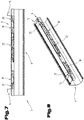
- FIGS. 7 and 8 is a section of another and possibly independent variant of the protective device 1 is shown, again with the same parts the same reference numerals or component designations as in the preceding Fig. 1 to 6 be used. To avoid unnecessary repetition, the detailed Description to the previous ones Fig. 1 to 6 referred to or referred to.
- the section shows the fastening strip 6 with the roller blind box 9 from the inside, ie in view from the room side of the window 1 (FIG. Fig. 1 ) or a door.
- This embodiment of the protective device 2 also has the two first clamping elements 18, which are preferably designed again as an eccentric, and arranged between the two first clamping elements 18 further clamping element 22, which is preferably designed again as a toggle on.
- the first clamping elements 18 is assigned in each case an angular element 15 and connected with these effect.
- the angle elements 15 on three legs, each two legs are arranged at an angle to each other.
- the angle is preferably not equal to 90 °, wherein in particular the outer leg of the frame 3 ( Fig. 1 ) engages with the middle leg an angle smaller than 90 ° and the middle leg with the arranged within the mounting bar 6 leg forms an angle of greater than 90 °.
- the angular elements 15 are each assigned at least one spring element 29, which is supported in the fastening strip 6.
- the spring elements 29 are at least approximately formed as leaf springs. About this spring elements 29, it is possible to keep the angle members 15 in the open position, whereby the attachment of the mounting bar 6 in the frame 3 is easier. In the closed position of the angle elements 15, the spring elements 29 are biased.
- the spring elements 29 are arranged with the angle elements 15 crossing each other.
- the spring elements 29 may be provided with a slot, so that the angle elements 15 can be inserted into the spring elements 29.
- the spring elements 29 may for example consist of a plastic.
- the clamping of the fastening strip 6 on the frame 3 takes place in this embodiment of the protective device 2 inter alia by bending the angle elements 15, that is, the lower, arranged in the fastening strip 6 legs of the angle elements 15, as a result of the action of the first clamping elements 18 on the angle elements 15 during clamping. It is thus achieved a greater way when clamping.
- angle elements 15 are formed latching in their recording.
- fastening strip 7 may be formed according to the mounting bar 6.
- the exemplary embodiments show or describe possible embodiments of the protective device 2 or of the window 1, wherein it should be noted at this point that various combinations of the individual variants are also possible with one another.
Landscapes
- Engineering & Computer Science (AREA)
- Structural Engineering (AREA)
- Architecture (AREA)
- Civil Engineering (AREA)
- Life Sciences & Earth Sciences (AREA)
- Insects & Arthropods (AREA)
- Pest Control & Pesticides (AREA)
- Blinds (AREA)
- Curtains And Furnishings For Windows Or Doors (AREA)
Applications Claiming Priority (1)
| Application Number | Priority Date | Filing Date | Title |
|---|---|---|---|
| ATA50971/2015A AT517909B1 (de) | 2015-11-13 | 2015-11-13 | Schutzvorrichtung |
Publications (2)
| Publication Number | Publication Date |
|---|---|
| EP3173569A1 true EP3173569A1 (fr) | 2017-05-31 |
| EP3173569B1 EP3173569B1 (fr) | 2018-08-15 |
Family
ID=57281146
Family Applications (1)
| Application Number | Title | Priority Date | Filing Date |
|---|---|---|---|
| EP16198168.3A Active EP3173569B1 (fr) | 2015-11-13 | 2016-11-10 | Dispositif de protection |
Country Status (2)
| Country | Link |
|---|---|
| EP (1) | EP3173569B1 (fr) |
| AT (1) | AT517909B1 (fr) |
Cited By (1)
| Publication number | Priority date | Publication date | Assignee | Title |
|---|---|---|---|---|
| IT201900007251A1 (it) * | 2019-05-27 | 2020-11-27 | Proline S R L | Dispositivo di fissaggio rapido per zanzariere |
Families Citing this family (1)
| Publication number | Priority date | Publication date | Assignee | Title |
|---|---|---|---|---|
| AT522526B1 (de) | 2019-04-19 | 2021-08-15 | Schlotterer Sonnenschutz Systeme Gmbh | Schutzrollo |
Citations (4)
| Publication number | Priority date | Publication date | Assignee | Title |
|---|---|---|---|---|
| DE102006005849A1 (de) * | 2005-02-08 | 2006-08-17 | Schlotterer Rolladen-Systeme Gmbh & Co. Kg | Insektenschutzvorrichtung |
| AT514207A4 (de) * | 2013-07-04 | 2014-11-15 | Stefan Hofinger | Vorrichtung zum Befestigen eines Rollos |
| DE102013013669A1 (de) * | 2013-08-16 | 2015-02-19 | Ips Insect Protect Systems Gmbh | Rahmensystem eines Partikelschutzgitters |
| DE102013013654A1 (de) * | 2013-08-16 | 2015-02-19 | Ips Insect Protect Systems Gmbh | Rahmensystem eines Partikelschutzgitters |
Family Cites Families (8)
| Publication number | Priority date | Publication date | Assignee | Title |
|---|---|---|---|---|
| DE29621112U1 (de) * | 1996-12-05 | 1997-01-23 | Solitec Systemtechnik Gmbh | Fliegenschutzgitter |
| DE19835390B4 (de) * | 1998-03-13 | 2012-10-18 | Norbert Neher | Insektenschutzvorrichtung |
| DE10133077A1 (de) * | 2001-07-07 | 2003-01-30 | Gerd Laemmermann | Insektenschutzgitter |
| EP1433920B1 (fr) * | 2002-12-23 | 2012-04-04 | Norbert Neher | Dispositif de protection contre insectes |
| DE202005011088U1 (de) * | 2005-07-14 | 2005-11-03 | Krüger, Robert | Insektenschutzvorrichtung |
| DE102006005610B4 (de) * | 2006-02-06 | 2008-02-21 | Kierschner, Inge | Insektenschutzrahmen |
| DE202009001409U1 (de) * | 2009-02-05 | 2009-04-16 | Reflexa-Werke Albrecht Gmbh | Insektenschutzvorrichtung |
| DE102011011113B4 (de) * | 2011-02-12 | 2013-01-31 | M.A.C.'s Holding Gmbh | Rahmensystem eines Partikelschutzgitters |
-
2015
- 2015-11-13 AT ATA50971/2015A patent/AT517909B1/de active
-
2016
- 2016-11-10 EP EP16198168.3A patent/EP3173569B1/fr active Active
Patent Citations (4)
| Publication number | Priority date | Publication date | Assignee | Title |
|---|---|---|---|---|
| DE102006005849A1 (de) * | 2005-02-08 | 2006-08-17 | Schlotterer Rolladen-Systeme Gmbh & Co. Kg | Insektenschutzvorrichtung |
| AT514207A4 (de) * | 2013-07-04 | 2014-11-15 | Stefan Hofinger | Vorrichtung zum Befestigen eines Rollos |
| DE102013013669A1 (de) * | 2013-08-16 | 2015-02-19 | Ips Insect Protect Systems Gmbh | Rahmensystem eines Partikelschutzgitters |
| DE102013013654A1 (de) * | 2013-08-16 | 2015-02-19 | Ips Insect Protect Systems Gmbh | Rahmensystem eines Partikelschutzgitters |
Cited By (1)
| Publication number | Priority date | Publication date | Assignee | Title |
|---|---|---|---|---|
| IT201900007251A1 (it) * | 2019-05-27 | 2020-11-27 | Proline S R L | Dispositivo di fissaggio rapido per zanzariere |
Also Published As
| Publication number | Publication date |
|---|---|
| EP3173569B1 (fr) | 2018-08-15 |
| AT517909A1 (de) | 2017-05-15 |
| AT517909B1 (de) | 2018-04-15 |
Similar Documents
| Publication | Publication Date | Title |
|---|---|---|
| DE69807438T3 (de) | Universelle befestigungs- und parallelführungsvorrichtung für eine fensterabschirmung | |
| EP1783315B1 (fr) | Support de cordon et capuchon d'extrémité pour une jalousie | |
| EP2631414A2 (fr) | Rail de guidage pour marquise verticale et marquise verticale | |
| EP3173569B1 (fr) | Dispositif de protection | |
| DE202022106449U1 (de) | Horizontal-Jalousie mit verdeckter Spannschnur | |
| DE102006059637A1 (de) | Senkrechtbeschattung | |
| DE202005011088U1 (de) | Insektenschutzvorrichtung | |
| DE102013003012A1 (de) | Flächenvorhangsystem | |
| DE10133077A1 (de) | Insektenschutzgitter | |
| DE102015209982A1 (de) | Insektenschutzvorhang, insbesondere Lamellenvorhang | |
| DE202018103057U1 (de) | Plisseejalousie | |
| AT516524B1 (de) | Insektenschutzsystem | |
| AT515118B1 (de) | Schutzvorrichtung | |
| EP3655612B1 (fr) | Store plissé avec rail de guidage télescopique | |
| DE102015215861A1 (de) | Sonnenschutzvorrichtung | |
| EP3805514A1 (fr) | Dispositif de fixation pour les dispositifs de protection de la lumière et/ou de la vue | |
| CH690968A5 (de) | Fensterladen mit Insektenschutz. | |
| DE202021100016U1 (de) | Führungsschiene für ein Rollo | |
| DE102021103718A1 (de) | Sonnenschutzanlage mit rollbarem Behang | |
| DE102021125670A1 (de) | Absturzsicherung für eine Gebäudeöffnung und Verfahren zur Montage einer Absturzsicherung | |
| DE102019117962A1 (de) | Rahmen mit integrierter Plisseeführungsschiene und Befestigungsfedern | |
| EP3447231A1 (fr) | Dispositif protège-doigt | |
| DE2725881A1 (de) | Blendschutzvorrichtung | |
| DE2527382B2 (de) | Schutzabdeckung für verschwenkbare Dachflächenfenster | |
| DE202018100750U1 (de) | Sicht- und Sonnenschutzvorrichtung für Fenster und Türen |
Legal Events
| Date | Code | Title | Description |
|---|---|---|---|
| PUAI | Public reference made under article 153(3) epc to a published international application that has entered the european phase |
Free format text: ORIGINAL CODE: 0009012 |
|
| AK | Designated contracting states |
Kind code of ref document: A1 Designated state(s): AL AT BE BG CH CY CZ DE DK EE ES FI FR GB GR HR HU IE IS IT LI LT LU LV MC MK MT NL NO PL PT RO RS SE SI SK SM TR |
|
| AX | Request for extension of the european patent |
Extension state: BA ME |
|
| 17P | Request for examination filed |
Effective date: 20171128 |
|
| RBV | Designated contracting states (corrected) |
Designated state(s): AL AT BE BG CH CY CZ DE DK EE ES FI FR GB GR HR HU IE IS IT LI LT LU LV MC MK MT NL NO PL PT RO RS SE SI SK SM TR |
|
| GRAP | Despatch of communication of intention to grant a patent |
Free format text: ORIGINAL CODE: EPIDOSNIGR1 |
|
| INTG | Intention to grant announced |
Effective date: 20180504 |
|
| GRAS | Grant fee paid |
Free format text: ORIGINAL CODE: EPIDOSNIGR3 |
|
| GRAA | (expected) grant |
Free format text: ORIGINAL CODE: 0009210 |
|
| AK | Designated contracting states |
Kind code of ref document: B1 Designated state(s): AL AT BE BG CH CY CZ DE DK EE ES FI FR GB GR HR HU IE IS IT LI LT LU LV MC MK MT NL NO PL PT RO RS SE SI SK SM TR |
|
| REG | Reference to a national code |
Ref country code: CH Ref legal event code: EP Ref country code: GB Ref legal event code: FG4D Free format text: NOT ENGLISH Ref country code: AT Ref legal event code: REF Ref document number: 1029968 Country of ref document: AT Kind code of ref document: T Effective date: 20180815 |
|
| REG | Reference to a national code |
Ref country code: IE Ref legal event code: FG4D Free format text: LANGUAGE OF EP DOCUMENT: GERMAN |
|
| REG | Reference to a national code |
Ref country code: DE Ref legal event code: R096 Ref document number: 502016001689 Country of ref document: DE |
|
| REG | Reference to a national code |
Ref country code: FR Ref legal event code: PLFP Year of fee payment: 3 |
|
| REG | Reference to a national code |
Ref country code: CH Ref legal event code: NV Representative=s name: ABP PATENT NETWORK AG, CH |
|
| REG | Reference to a national code |
Ref country code: NL Ref legal event code: FP |
|
| REG | Reference to a national code |
Ref country code: LT Ref legal event code: MG4D |
|
| PG25 | Lapsed in a contracting state [announced via postgrant information from national office to epo] |
Ref country code: NO Free format text: LAPSE BECAUSE OF FAILURE TO SUBMIT A TRANSLATION OF THE DESCRIPTION OR TO PAY THE FEE WITHIN THE PRESCRIBED TIME-LIMIT Effective date: 20181115 Ref country code: GR Free format text: LAPSE BECAUSE OF FAILURE TO SUBMIT A TRANSLATION OF THE DESCRIPTION OR TO PAY THE FEE WITHIN THE PRESCRIBED TIME-LIMIT Effective date: 20181116 Ref country code: RS Free format text: LAPSE BECAUSE OF FAILURE TO SUBMIT A TRANSLATION OF THE DESCRIPTION OR TO PAY THE FEE WITHIN THE PRESCRIBED TIME-LIMIT Effective date: 20180815 Ref country code: SE Free format text: LAPSE BECAUSE OF FAILURE TO SUBMIT A TRANSLATION OF THE DESCRIPTION OR TO PAY THE FEE WITHIN THE PRESCRIBED TIME-LIMIT Effective date: 20180815 Ref country code: FI Free format text: LAPSE BECAUSE OF FAILURE TO SUBMIT A TRANSLATION OF THE DESCRIPTION OR TO PAY THE FEE WITHIN THE PRESCRIBED TIME-LIMIT Effective date: 20180815 Ref country code: LT Free format text: LAPSE BECAUSE OF FAILURE TO SUBMIT A TRANSLATION OF THE DESCRIPTION OR TO PAY THE FEE WITHIN THE PRESCRIBED TIME-LIMIT Effective date: 20180815 Ref country code: IS Free format text: LAPSE BECAUSE OF FAILURE TO SUBMIT A TRANSLATION OF THE DESCRIPTION OR TO PAY THE FEE WITHIN THE PRESCRIBED TIME-LIMIT Effective date: 20181215 Ref country code: BG Free format text: LAPSE BECAUSE OF FAILURE TO SUBMIT A TRANSLATION OF THE DESCRIPTION OR TO PAY THE FEE WITHIN THE PRESCRIBED TIME-LIMIT Effective date: 20181115 |
|
| PG25 | Lapsed in a contracting state [announced via postgrant information from national office to epo] |
Ref country code: AL Free format text: LAPSE BECAUSE OF FAILURE TO SUBMIT A TRANSLATION OF THE DESCRIPTION OR TO PAY THE FEE WITHIN THE PRESCRIBED TIME-LIMIT Effective date: 20180815 Ref country code: LV Free format text: LAPSE BECAUSE OF FAILURE TO SUBMIT A TRANSLATION OF THE DESCRIPTION OR TO PAY THE FEE WITHIN THE PRESCRIBED TIME-LIMIT Effective date: 20180815 Ref country code: HR Free format text: LAPSE BECAUSE OF FAILURE TO SUBMIT A TRANSLATION OF THE DESCRIPTION OR TO PAY THE FEE WITHIN THE PRESCRIBED TIME-LIMIT Effective date: 20180815 |
|
| PG25 | Lapsed in a contracting state [announced via postgrant information from national office to epo] |
Ref country code: PL Free format text: LAPSE BECAUSE OF FAILURE TO SUBMIT A TRANSLATION OF THE DESCRIPTION OR TO PAY THE FEE WITHIN THE PRESCRIBED TIME-LIMIT Effective date: 20180815 Ref country code: EE Free format text: LAPSE BECAUSE OF FAILURE TO SUBMIT A TRANSLATION OF THE DESCRIPTION OR TO PAY THE FEE WITHIN THE PRESCRIBED TIME-LIMIT Effective date: 20180815 Ref country code: ES Free format text: LAPSE BECAUSE OF FAILURE TO SUBMIT A TRANSLATION OF THE DESCRIPTION OR TO PAY THE FEE WITHIN THE PRESCRIBED TIME-LIMIT Effective date: 20180815 Ref country code: RO Free format text: LAPSE BECAUSE OF FAILURE TO SUBMIT A TRANSLATION OF THE DESCRIPTION OR TO PAY THE FEE WITHIN THE PRESCRIBED TIME-LIMIT Effective date: 20180815 Ref country code: CZ Free format text: LAPSE BECAUSE OF FAILURE TO SUBMIT A TRANSLATION OF THE DESCRIPTION OR TO PAY THE FEE WITHIN THE PRESCRIBED TIME-LIMIT Effective date: 20180815 |
|
| REG | Reference to a national code |
Ref country code: DE Ref legal event code: R097 Ref document number: 502016001689 Country of ref document: DE |
|
| PG25 | Lapsed in a contracting state [announced via postgrant information from national office to epo] |
Ref country code: SK Free format text: LAPSE BECAUSE OF FAILURE TO SUBMIT A TRANSLATION OF THE DESCRIPTION OR TO PAY THE FEE WITHIN THE PRESCRIBED TIME-LIMIT Effective date: 20180815 Ref country code: SM Free format text: LAPSE BECAUSE OF FAILURE TO SUBMIT A TRANSLATION OF THE DESCRIPTION OR TO PAY THE FEE WITHIN THE PRESCRIBED TIME-LIMIT Effective date: 20180815 Ref country code: DK Free format text: LAPSE BECAUSE OF FAILURE TO SUBMIT A TRANSLATION OF THE DESCRIPTION OR TO PAY THE FEE WITHIN THE PRESCRIBED TIME-LIMIT Effective date: 20180815 |
|
| PLBE | No opposition filed within time limit |
Free format text: ORIGINAL CODE: 0009261 |
|
| STAA | Information on the status of an ep patent application or granted ep patent |
Free format text: STATUS: NO OPPOSITION FILED WITHIN TIME LIMIT |
|
| 26N | No opposition filed |
Effective date: 20190516 |
|
| PG25 | Lapsed in a contracting state [announced via postgrant information from national office to epo] |
Ref country code: MC Free format text: LAPSE BECAUSE OF FAILURE TO SUBMIT A TRANSLATION OF THE DESCRIPTION OR TO PAY THE FEE WITHIN THE PRESCRIBED TIME-LIMIT Effective date: 20180815 Ref country code: LU Free format text: LAPSE BECAUSE OF NON-PAYMENT OF DUE FEES Effective date: 20181110 |
|
| REG | Reference to a national code |
Ref country code: IE Ref legal event code: MM4A |
|
| PG25 | Lapsed in a contracting state [announced via postgrant information from national office to epo] |
Ref country code: SI Free format text: LAPSE BECAUSE OF FAILURE TO SUBMIT A TRANSLATION OF THE DESCRIPTION OR TO PAY THE FEE WITHIN THE PRESCRIBED TIME-LIMIT Effective date: 20180815 |
|
| PG25 | Lapsed in a contracting state [announced via postgrant information from national office to epo] |
Ref country code: IE Free format text: LAPSE BECAUSE OF NON-PAYMENT OF DUE FEES Effective date: 20181110 |
|
| PG25 | Lapsed in a contracting state [announced via postgrant information from national office to epo] |
Ref country code: MT Free format text: LAPSE BECAUSE OF FAILURE TO SUBMIT A TRANSLATION OF THE DESCRIPTION OR TO PAY THE FEE WITHIN THE PRESCRIBED TIME-LIMIT Effective date: 20180815 |
|
| PG25 | Lapsed in a contracting state [announced via postgrant information from national office to epo] |
Ref country code: TR Free format text: LAPSE BECAUSE OF FAILURE TO SUBMIT A TRANSLATION OF THE DESCRIPTION OR TO PAY THE FEE WITHIN THE PRESCRIBED TIME-LIMIT Effective date: 20180815 |
|
| PG25 | Lapsed in a contracting state [announced via postgrant information from national office to epo] |
Ref country code: PT Free format text: LAPSE BECAUSE OF FAILURE TO SUBMIT A TRANSLATION OF THE DESCRIPTION OR TO PAY THE FEE WITHIN THE PRESCRIBED TIME-LIMIT Effective date: 20180815 |
|
| PG25 | Lapsed in a contracting state [announced via postgrant information from national office to epo] |
Ref country code: CY Free format text: LAPSE BECAUSE OF FAILURE TO SUBMIT A TRANSLATION OF THE DESCRIPTION OR TO PAY THE FEE WITHIN THE PRESCRIBED TIME-LIMIT Effective date: 20180815 Ref country code: MK Free format text: LAPSE BECAUSE OF NON-PAYMENT OF DUE FEES Effective date: 20180815 Ref country code: HU Free format text: LAPSE BECAUSE OF FAILURE TO SUBMIT A TRANSLATION OF THE DESCRIPTION OR TO PAY THE FEE WITHIN THE PRESCRIBED TIME-LIMIT; INVALID AB INITIO Effective date: 20161110 |
|
| GBPC | Gb: european patent ceased through non-payment of renewal fee |
Effective date: 20201110 |
|
| PG25 | Lapsed in a contracting state [announced via postgrant information from national office to epo] |
Ref country code: GB Free format text: LAPSE BECAUSE OF NON-PAYMENT OF DUE FEES Effective date: 20201110 |
|
| P01 | Opt-out of the competence of the unified patent court (upc) registered |
Effective date: 20230621 |
|
| PGFP | Annual fee paid to national office [announced via postgrant information from national office to epo] |
Ref country code: NL Payment date: 20231114 Year of fee payment: 8 |
|
| PGFP | Annual fee paid to national office [announced via postgrant information from national office to epo] |
Ref country code: IT Payment date: 20231115 Year of fee payment: 8 Ref country code: DE Payment date: 20231017 Year of fee payment: 8 Ref country code: CH Payment date: 20231201 Year of fee payment: 8 Ref country code: AT Payment date: 20231004 Year of fee payment: 8 Ref country code: FR Payment date: 20231009 Year of fee payment: 8 |
|
| PGFP | Annual fee paid to national office [announced via postgrant information from national office to epo] |
Ref country code: BE Payment date: 20231009 Year of fee payment: 8 |