EP3169372B1 - Controllable self-annealing microgel particles for biomedical applications - Google Patents
Controllable self-annealing microgel particles for biomedical applications Download PDFInfo
- Publication number
- EP3169372B1 EP3169372B1 EP15821310.8A EP15821310A EP3169372B1 EP 3169372 B1 EP3169372 B1 EP 3169372B1 EP 15821310 A EP15821310 A EP 15821310A EP 3169372 B1 EP3169372 B1 EP 3169372B1
- Authority
- EP
- European Patent Office
- Prior art keywords
- microgel particles
- scaffold
- microgel
- tissue
- annealing
- Prior art date
- Legal status (The legal status is an assumption and is not a legal conclusion. Google has not performed a legal analysis and makes no representation as to the accuracy of the status listed.)
- Active
Links
Images


Classifications
-
- A—HUMAN NECESSITIES
- A61—MEDICAL OR VETERINARY SCIENCE; HYGIENE
- A61K—PREPARATIONS FOR MEDICAL, DENTAL OR TOILETRY PURPOSES
- A61K31/00—Medicinal preparations containing organic active ingredients
- A61K31/74—Synthetic polymeric materials
- A61K31/795—Polymers containing sulfur
-
- A—HUMAN NECESSITIES
- A61—MEDICAL OR VETERINARY SCIENCE; HYGIENE
- A61K—PREPARATIONS FOR MEDICAL, DENTAL OR TOILETRY PURPOSES
- A61K47/00—Medicinal preparations characterised by the non-active ingredients used, e.g. carriers or inert additives; Targeting or modifying agents chemically bound to the active ingredient
- A61K47/50—Medicinal preparations characterised by the non-active ingredients used, e.g. carriers or inert additives; Targeting or modifying agents chemically bound to the active ingredient the non-active ingredient being chemically bound to the active ingredient, e.g. polymer-drug conjugates
- A61K47/51—Medicinal preparations characterised by the non-active ingredients used, e.g. carriers or inert additives; Targeting or modifying agents chemically bound to the active ingredient the non-active ingredient being chemically bound to the active ingredient, e.g. polymer-drug conjugates the non-active ingredient being a modifying agent
- A61K47/62—Medicinal preparations characterised by the non-active ingredients used, e.g. carriers or inert additives; Targeting or modifying agents chemically bound to the active ingredient the non-active ingredient being chemically bound to the active ingredient, e.g. polymer-drug conjugates the non-active ingredient being a modifying agent the modifying agent being a protein, peptide or polyamino acid
-
- A—HUMAN NECESSITIES
- A61—MEDICAL OR VETERINARY SCIENCE; HYGIENE
- A61K—PREPARATIONS FOR MEDICAL, DENTAL OR TOILETRY PURPOSES
- A61K9/00—Medicinal preparations characterised by special physical form
- A61K9/06—Ointments; Bases therefor; Other semi-solid forms, e.g. creams, sticks, gels
-
- A—HUMAN NECESSITIES
- A61—MEDICAL OR VETERINARY SCIENCE; HYGIENE
- A61L—METHODS OR APPARATUS FOR STERILISING MATERIALS OR OBJECTS IN GENERAL; DISINFECTION, STERILISATION OR DEODORISATION OF AIR; CHEMICAL ASPECTS OF BANDAGES, DRESSINGS, ABSORBENT PADS OR SURGICAL ARTICLES; MATERIALS FOR BANDAGES, DRESSINGS, ABSORBENT PADS OR SURGICAL ARTICLES
- A61L26/00—Chemical aspects of, or use of materials for, wound dressings or bandages in liquid, gel or powder form
- A61L26/0009—Chemical aspects of, or use of materials for, wound dressings or bandages in liquid, gel or powder form containing macromolecular materials
- A61L26/0019—Chemical aspects of, or use of materials for, wound dressings or bandages in liquid, gel or powder form containing macromolecular materials obtained otherwise than by reactions only involving carbon-to-carbon unsaturated bonds
-
- A—HUMAN NECESSITIES
- A61—MEDICAL OR VETERINARY SCIENCE; HYGIENE
- A61L—METHODS OR APPARATUS FOR STERILISING MATERIALS OR OBJECTS IN GENERAL; DISINFECTION, STERILISATION OR DEODORISATION OF AIR; CHEMICAL ASPECTS OF BANDAGES, DRESSINGS, ABSORBENT PADS OR SURGICAL ARTICLES; MATERIALS FOR BANDAGES, DRESSINGS, ABSORBENT PADS OR SURGICAL ARTICLES
- A61L26/00—Chemical aspects of, or use of materials for, wound dressings or bandages in liquid, gel or powder form
- A61L26/0009—Chemical aspects of, or use of materials for, wound dressings or bandages in liquid, gel or powder form containing macromolecular materials
- A61L26/0028—Polypeptides; Proteins; Degradation products thereof
- A61L26/0047—Specific proteins or polypeptides not covered by groups A61L26/0033 - A61L26/0042
-
- A—HUMAN NECESSITIES
- A61—MEDICAL OR VETERINARY SCIENCE; HYGIENE
- A61L—METHODS OR APPARATUS FOR STERILISING MATERIALS OR OBJECTS IN GENERAL; DISINFECTION, STERILISATION OR DEODORISATION OF AIR; CHEMICAL ASPECTS OF BANDAGES, DRESSINGS, ABSORBENT PADS OR SURGICAL ARTICLES; MATERIALS FOR BANDAGES, DRESSINGS, ABSORBENT PADS OR SURGICAL ARTICLES
- A61L26/00—Chemical aspects of, or use of materials for, wound dressings or bandages in liquid, gel or powder form
- A61L26/0061—Use of materials characterised by their function or physical properties
- A61L26/0066—Medicaments; Biocides
-
- A—HUMAN NECESSITIES
- A61—MEDICAL OR VETERINARY SCIENCE; HYGIENE
- A61L—METHODS OR APPARATUS FOR STERILISING MATERIALS OR OBJECTS IN GENERAL; DISINFECTION, STERILISATION OR DEODORISATION OF AIR; CHEMICAL ASPECTS OF BANDAGES, DRESSINGS, ABSORBENT PADS OR SURGICAL ARTICLES; MATERIALS FOR BANDAGES, DRESSINGS, ABSORBENT PADS OR SURGICAL ARTICLES
- A61L26/00—Chemical aspects of, or use of materials for, wound dressings or bandages in liquid, gel or powder form
- A61L26/0061—Use of materials characterised by their function or physical properties
- A61L26/008—Hydrogels or hydrocolloids
-
- A—HUMAN NECESSITIES
- A61—MEDICAL OR VETERINARY SCIENCE; HYGIENE
- A61L—METHODS OR APPARATUS FOR STERILISING MATERIALS OR OBJECTS IN GENERAL; DISINFECTION, STERILISATION OR DEODORISATION OF AIR; CHEMICAL ASPECTS OF BANDAGES, DRESSINGS, ABSORBENT PADS OR SURGICAL ARTICLES; MATERIALS FOR BANDAGES, DRESSINGS, ABSORBENT PADS OR SURGICAL ARTICLES
- A61L26/00—Chemical aspects of, or use of materials for, wound dressings or bandages in liquid, gel or powder form
- A61L26/0061—Use of materials characterised by their function or physical properties
- A61L26/0085—Porous materials, e.g. foams or sponges
-
- A—HUMAN NECESSITIES
- A61—MEDICAL OR VETERINARY SCIENCE; HYGIENE
- A61L—METHODS OR APPARATUS FOR STERILISING MATERIALS OR OBJECTS IN GENERAL; DISINFECTION, STERILISATION OR DEODORISATION OF AIR; CHEMICAL ASPECTS OF BANDAGES, DRESSINGS, ABSORBENT PADS OR SURGICAL ARTICLES; MATERIALS FOR BANDAGES, DRESSINGS, ABSORBENT PADS OR SURGICAL ARTICLES
- A61L26/00—Chemical aspects of, or use of materials for, wound dressings or bandages in liquid, gel or powder form
- A61L26/0061—Use of materials characterised by their function or physical properties
- A61L26/009—Materials resorbable by the body
-
- A—HUMAN NECESSITIES
- A61—MEDICAL OR VETERINARY SCIENCE; HYGIENE
- A61L—METHODS OR APPARATUS FOR STERILISING MATERIALS OR OBJECTS IN GENERAL; DISINFECTION, STERILISATION OR DEODORISATION OF AIR; CHEMICAL ASPECTS OF BANDAGES, DRESSINGS, ABSORBENT PADS OR SURGICAL ARTICLES; MATERIALS FOR BANDAGES, DRESSINGS, ABSORBENT PADS OR SURGICAL ARTICLES
- A61L27/00—Materials for grafts or prostheses or for coating grafts or prostheses
- A61L27/14—Macromolecular materials
- A61L27/18—Macromolecular materials obtained otherwise than by reactions only involving carbon-to-carbon unsaturated bonds
-
- A—HUMAN NECESSITIES
- A61—MEDICAL OR VETERINARY SCIENCE; HYGIENE
- A61L—METHODS OR APPARATUS FOR STERILISING MATERIALS OR OBJECTS IN GENERAL; DISINFECTION, STERILISATION OR DEODORISATION OF AIR; CHEMICAL ASPECTS OF BANDAGES, DRESSINGS, ABSORBENT PADS OR SURGICAL ARTICLES; MATERIALS FOR BANDAGES, DRESSINGS, ABSORBENT PADS OR SURGICAL ARTICLES
- A61L27/00—Materials for grafts or prostheses or for coating grafts or prostheses
- A61L27/14—Macromolecular materials
- A61L27/22—Polypeptides or derivatives thereof, e.g. degradation products
- A61L27/227—Other specific proteins or polypeptides not covered by A61L27/222, A61L27/225 or A61L27/24
-
- A—HUMAN NECESSITIES
- A61—MEDICAL OR VETERINARY SCIENCE; HYGIENE
- A61L—METHODS OR APPARATUS FOR STERILISING MATERIALS OR OBJECTS IN GENERAL; DISINFECTION, STERILISATION OR DEODORISATION OF AIR; CHEMICAL ASPECTS OF BANDAGES, DRESSINGS, ABSORBENT PADS OR SURGICAL ARTICLES; MATERIALS FOR BANDAGES, DRESSINGS, ABSORBENT PADS OR SURGICAL ARTICLES
- A61L27/00—Materials for grafts or prostheses or for coating grafts or prostheses
- A61L27/50—Materials characterised by their function or physical properties, e.g. injectable or lubricating compositions, shape-memory materials, surface modified materials
- A61L27/52—Hydrogels or hydrocolloids
-
- A—HUMAN NECESSITIES
- A61—MEDICAL OR VETERINARY SCIENCE; HYGIENE
- A61L—METHODS OR APPARATUS FOR STERILISING MATERIALS OR OBJECTS IN GENERAL; DISINFECTION, STERILISATION OR DEODORISATION OF AIR; CHEMICAL ASPECTS OF BANDAGES, DRESSINGS, ABSORBENT PADS OR SURGICAL ARTICLES; MATERIALS FOR BANDAGES, DRESSINGS, ABSORBENT PADS OR SURGICAL ARTICLES
- A61L27/00—Materials for grafts or prostheses or for coating grafts or prostheses
- A61L27/50—Materials characterised by their function or physical properties, e.g. injectable or lubricating compositions, shape-memory materials, surface modified materials
- A61L27/54—Biologically active materials, e.g. therapeutic substances
-
- A—HUMAN NECESSITIES
- A61—MEDICAL OR VETERINARY SCIENCE; HYGIENE
- A61L—METHODS OR APPARATUS FOR STERILISING MATERIALS OR OBJECTS IN GENERAL; DISINFECTION, STERILISATION OR DEODORISATION OF AIR; CHEMICAL ASPECTS OF BANDAGES, DRESSINGS, ABSORBENT PADS OR SURGICAL ARTICLES; MATERIALS FOR BANDAGES, DRESSINGS, ABSORBENT PADS OR SURGICAL ARTICLES
- A61L27/00—Materials for grafts or prostheses or for coating grafts or prostheses
- A61L27/50—Materials characterised by their function or physical properties, e.g. injectable or lubricating compositions, shape-memory materials, surface modified materials
- A61L27/56—Porous materials, e.g. foams or sponges
-
- A—HUMAN NECESSITIES
- A61—MEDICAL OR VETERINARY SCIENCE; HYGIENE
- A61L—METHODS OR APPARATUS FOR STERILISING MATERIALS OR OBJECTS IN GENERAL; DISINFECTION, STERILISATION OR DEODORISATION OF AIR; CHEMICAL ASPECTS OF BANDAGES, DRESSINGS, ABSORBENT PADS OR SURGICAL ARTICLES; MATERIALS FOR BANDAGES, DRESSINGS, ABSORBENT PADS OR SURGICAL ARTICLES
- A61L27/00—Materials for grafts or prostheses or for coating grafts or prostheses
- A61L27/50—Materials characterised by their function or physical properties, e.g. injectable or lubricating compositions, shape-memory materials, surface modified materials
- A61L27/58—Materials at least partially resorbable by the body
-
- A—HUMAN NECESSITIES
- A61—MEDICAL OR VETERINARY SCIENCE; HYGIENE
- A61L—METHODS OR APPARATUS FOR STERILISING MATERIALS OR OBJECTS IN GENERAL; DISINFECTION, STERILISATION OR DEODORISATION OF AIR; CHEMICAL ASPECTS OF BANDAGES, DRESSINGS, ABSORBENT PADS OR SURGICAL ARTICLES; MATERIALS FOR BANDAGES, DRESSINGS, ABSORBENT PADS OR SURGICAL ARTICLES
- A61L2300/00—Biologically active materials used in bandages, wound dressings, absorbent pads or medical devices
- A61L2300/20—Biologically active materials used in bandages, wound dressings, absorbent pads or medical devices containing or releasing organic materials
- A61L2300/252—Polypeptides, proteins, e.g. glycoproteins, lipoproteins, cytokines
-
- A—HUMAN NECESSITIES
- A61—MEDICAL OR VETERINARY SCIENCE; HYGIENE
- A61L—METHODS OR APPARATUS FOR STERILISING MATERIALS OR OBJECTS IN GENERAL; DISINFECTION, STERILISATION OR DEODORISATION OF AIR; CHEMICAL ASPECTS OF BANDAGES, DRESSINGS, ABSORBENT PADS OR SURGICAL ARTICLES; MATERIALS FOR BANDAGES, DRESSINGS, ABSORBENT PADS OR SURGICAL ARTICLES
- A61L2300/00—Biologically active materials used in bandages, wound dressings, absorbent pads or medical devices
- A61L2300/40—Biologically active materials used in bandages, wound dressings, absorbent pads or medical devices characterised by a specific therapeutic activity or mode of action
- A61L2300/412—Tissue-regenerating or healing or proliferative agents
-
- A—HUMAN NECESSITIES
- A61—MEDICAL OR VETERINARY SCIENCE; HYGIENE
- A61L—METHODS OR APPARATUS FOR STERILISING MATERIALS OR OBJECTS IN GENERAL; DISINFECTION, STERILISATION OR DEODORISATION OF AIR; CHEMICAL ASPECTS OF BANDAGES, DRESSINGS, ABSORBENT PADS OR SURGICAL ARTICLES; MATERIALS FOR BANDAGES, DRESSINGS, ABSORBENT PADS OR SURGICAL ARTICLES
- A61L2400/00—Materials characterised by their function or physical properties
- A61L2400/06—Flowable or injectable implant compositions
-
- A—HUMAN NECESSITIES
- A61—MEDICAL OR VETERINARY SCIENCE; HYGIENE
- A61L—METHODS OR APPARATUS FOR STERILISING MATERIALS OR OBJECTS IN GENERAL; DISINFECTION, STERILISATION OR DEODORISATION OF AIR; CHEMICAL ASPECTS OF BANDAGES, DRESSINGS, ABSORBENT PADS OR SURGICAL ARTICLES; MATERIALS FOR BANDAGES, DRESSINGS, ABSORBENT PADS OR SURGICAL ARTICLES
- A61L2430/00—Materials or treatment for tissue regeneration
- A61L2430/34—Materials or treatment for tissue regeneration for soft tissue reconstruction
Definitions
- the technical field relates generally to the field of wound treatment, and in particular, the use of microgel particles and scaffolds including the particles for treating and sealing wounds and for tissue filler applications.
- a central concept tied to the generation and regeneration of tissue is collective cell migration, a process by which entire networks of cells move together into an area of development to facilitate the formation of functional tissue.
- researchers have sought to develop would healing agents; however, these materials display batch-to-batch variability and exhibit degradation rates that limit extended structural support for growing tissues.
- Synthetic materials are more tunable than natural materials and their mechanical properties have been engineered to allow use with a wide range of tissue types. Despite this tunability, however, synthetic injectable biomaterials have been limited to non-porous or nanoporous scaffolds that require physical degradation for cellular migration through the material.
- Porous synthetic hydrogels that contain pre-formed microscale interconnected pores allow greater cell mobility without the need for degradation, circumventing the trade-off between cell mobility and material stability inherent to non-porous scaffolds.
- the typical mode of pore formation includes the toxic removal of porogens, or the degradation of encapsulated microparticles, which requires these constructs to be either cast ex vivo, preventing them from seamlessly integrating with the surrounding tissue like an injectable biomaterial or requires long-term in vivo development to resolve the porous structure.
- STAR Sphere Templated Anigiogenic Regeneration
- STAR scaffolds are formed by sintering together an array of packed beads of controlled size, casting a polymer into the interstitial space between the beads, and dissolving away the beads to yield a pore network of interconnected spherical voids.
- these conventional processes require the toxic removal of porogens.
- Prior art document US 2008/0193536 A1 discloses cell-lade hydrogels and hydrogels assemblies that are used for tissue engineering.
- the hydrogel assemblies comprise polygonal sub-units that connect together in a geometric lock-and-key tape arrangement to form hydrogel assemblies.
- the instant inventors have identified the gold standard of the development of interconnected microporous scaffolds that allow for interconnected cell networks and collective migration without the need for scaffold degradation or invasive procedures for implantation is essential for bulk integration with the surrounding tissue.
- these materials should facilitate collective cell migration that mediates regeneration while providing molecular cues to promote wound healing and niche recognition.
- the instant inventors have also identified that these materials must be able to be seamlessly replaced by migrating cells and natural matrix, provide a stable structural support prior to replacement, and be easily delivered and conform to the site of injury to minimize fibrotic and inflammatory responses.
- the technology described herein utilizes chemistry to generate tiny microgels that can be assembled into a large unit, leaving behind a path for cellular infiltration.
- the result is a packed cluster of microscopic synthetic polymer bodies (spheres) attached at their surfaces, akin to a jar of gumballs that are stuck together.
- the cluster creates a scaffold of microporous annealed particles (e.g., a porous gel scaffold) that fills in the wound.
- New tissue quickly grows into the voids between the microgel particles, and as the microgel particles degrade into the body, a matrix of newly grown tissue is left where the wound once was. New tissue continues growing until the wound is completely healed.
- microgel systems described herein represents a substantial improvement over conventional products.
- the technologies described herein do not require added growth factors to attract cells into the material.
- the geometry of the described microgel networks entice cells to migrate into the microgel.
- microgels can promote the growth of new cells and formation of networks of connected cells at previously unseen rates. For example, during in vivo studies, significant tissue regeneration was observed in the first 48 hours, with much more healing over five days compared to conventional materials in use today.
- the technologies described herein are useful for a wide array of applications.
- the disclosed microgel technology can be used for wound applications, including acute damage, like lacerations and surgical wound closures, and also more chronic applications like diabetic ulcers and large-area burn wounds.
- the hydrogel scaffolds described herein can also be useful in trauma situations, such as battlefields or emergency rooms.
- microporous gels described herein are flowable and/or injectable and can be applied in multiple different ways, including for example topically or by injection. Injected and/or flowable microporous gels can be inserted transdermally or into deep tissue. Flowable microporous gels can also be administered topically to the dermis and other tissues.
- the invention relates to a flowable microporous hydrogel system according to claim 1.
- Advantageous embodiments of the invention are formed by the dependent claims.
- an annealing agent is applied to the plurality of microgel particles, the microgel particles form a covalently-stabilized scaffold of microgel particles having interstitial spaces therein.
- the system is specifically engineered for biomedical applications.
- the microporous gel particles further comprise a crosslinker, wherein the crosslinker includes a matrix metalloprotease (MMP)-degradable crosslinker.
- An annealing agent comprises Factor XIIIa.
- the annealing agent comprises Eosin Y, a free radical transfer agent, or a combination thereof.
- a microporous gel system comprising: a collection of microgel particles comprising a backbone polymer having one or more cell attachment moieties, one or more annealing components, and one or more biodegradable network crosslinker components; and an endogenous or exogenous annealing agent that links the microgel particles together in situ via the annealing components to form a covalently-stabilized scaffold of microgel particles having interstitial spaces therein.
- the backbone polymer comprises poly(ethylene glycol) vinyl sulfone.
- the one or more cell attachment moieties comprise a RGD peptide or a fragment thereof.
- the one or more cell attachment moieties comprise SEQ ID NO: 3 or a fragment thereof.
- the one or more annealing components comprise a K-peptide and a Q-peptide.
- the K-peptide comprises a Factor XIIIa-recognized lysine group and the Q-peptide comprises a Factor XIIIa-recognized glutamine group.
- the biodegradable network crosslinker component comprises a matrix metalloprotease (MMP)-degradable crosslinker.
- MMP matrix metalloprotease
- the (MMP)-degradable crosslinker comprises D-amino acid.
- the collection of microgel particles comprises microgel particles of two or more types.
- the microgel particles of a first type comprise (MMP)-degradable crosslinker comprising D-amino acid
- microgel particles of a second type comprise (MMP)-degradable crosslinker comprising only L-amino acid.
- the system or device comprises a single compartment delivery device containing the collection of microgel particles and the annealing agent.
- the system further comprises a double compartment delivery device, wherein one compartment contains the aqueous solution containing plurality of microgel particles and a first annealing agent precursor and the second compartment contains the aqueous solution containing plurality of microgel particles and a second annealing agent precursor, wherein the annealing agent is formed by the presence of the first and second annealing agent precursors.
- a solid microgel scaffold for biomedical applications such as wound healing is disclosed that is formed when a plurality of microgel particles are annealed to one another in an annealing reaction.
- the annealing reaction in one aspect of the subject matter described herein forms covalent bonds between adjacent microgel particles.
- the scaffold in the post-annealed state, the scaffold forms a three-dimensional structure that conforms to the site of application or delivery. Because of the imperfect packing of the microgel particles, the annealed scaffold formed from the particles includes interstitial spaces formed therein where cells can migrate, bind, and grow.
- the formed scaffold structure is porous upon annealing in the wound or other delivery site (unlike the non-porous solid scaffold provided by fibrin-based products).
- This porosity includes the interstitial spaces mentioned above as well as nanoscopic pores that may be created or formed in the particles themselves.
- the micro-porosity of the scaffold structure allows for high diffusivity of nutrients, cell growth and differentiation factors, as well as cell migration, ingrowth, and penetration.
- the microporosity of the scaffold provides for accelerated healing or improved therapeutic delivery of drugs or medicaments over conventional fibrin glue, hyper-branched polymers, or polymers with degradable crosslinker options, because of the enhanced cell migration through interstitial spaces while maintaining overall scaffold integrity.
- the degradation profile and physical properties are improved, for example, by having a larger available range and a wider array of biological signals or therapeutically-active chemicals can be included within the material (e.g., antibiotics, steroids, growth factors, and the like can be loaded into the scaffold).
- biological signals or therapeutically-active chemicals can be included within the material (e.g., antibiotics, steroids, growth factors, and the like can be loaded into the scaffold).
- the release or elution of the drugs, compounds, or other material to trigger or control biological activity in certain embodiments, can be tuned through modification of the desired biomaterial.
- the signal compounds or molecules discussed above may be exposed to the tissue during the healing process or upon degradation of the scaffold.
- the signal compounds or molecules may also be released or eluted into the affected area after initial placement of the scaffold at the delivery site.
- One advantage of the subject matter described herein beyond methods such as the STAR TM technology is that the formation of a scaffold occurs in vivo, allowing it to completely fill the desired space and be tuned to bind (chemically or otherwise) to the surrounding tissue.
- the pre-delivery formation of the microgel particles allows for controlled mechanical tunability of the resultant formed scaffold to match the properties of the surrounding tissue. These capabilities result in a better seal and overall integration with the tissue. Greater integration results in decreased possibility of material failure and enhanced long-term regeneration. This also helps prevent contamination from the environment.
- the microporous nature of the annealed scaffold is beneficial to reduce immune foreign body response to the scaffold.
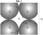
- FIG. 1 illustrates a portion of the formed three dimensional scaffold 10 that is formed by a plurality of annealed microgel particles 12.
- the scaffold 10 includes interstitial spaces therein 14 that are voids that form micropores within the larger scaffold 10.
- the interstitial spaces 14 have dimensions and geometrical profiles that permit the infiltration, binding, and growth of cells.
- the microporous nature of the scaffold 10 disclosed herein involves a network of interstitial spaces or voids 14 located between annealed microgel particles 12 that form the larger scaffold structure.
- the interstitial spaces or voids 14 created within the scaffold 10 exhibit negative concavity ( e . g., the interior void surface is convex).
- FIG. 1 illustrates a portion of the formed three dimensional scaffold 10 that is formed by a plurality of annealed microgel particles 12.
- the scaffold 10 includes interstitial spaces therein 14 that are voids that form micropores within the larger scaffold 10.
- the interstitial spaces 14 have dimensions and geometrical profiles that
- FIG. 1 illustrates an exemplary void 14 with void walls 16 exhibiting negative concavity.
- the negative concavity is caused because the microgel particles 12 that are annealed to one another are generally or substantially spherical in shape. This allows for the packing of microgel particles 12 that, according to one embodiment, produces a low void volume fraction between about 10% and about 50% and, in another embodiment between about 26% to about 36%. While the void volume fraction is low, the negative concavity exhibited in certain embodiments within the network of voids 14 provides a relatively high surface area to void volume for cells to interact with. For a given volume of cells, they would then, on average, be exposed to even more and larger surfaces ( e.g., on the void walls 16) to interact within the network of voids in the scaffold 10.
- the void network consists of regions where microgel surfaces are in close proximity (e.g., near neighboring annealed microgel particles 12) leading to high surface area adhesive regions for cells to adhere and rapidly migrate through, while neighboring regions further in the gaps between microgel particles 12 have a larger void space that can enable cell and tissue growth in this space. Therefore the combined adjacency of the tight void areas and more spacious void gaps is expected to have a beneficial effect on tissue ingrowth and regrowth, compared to either entirely small voids or all larger voids.
- the scaffold 10 is formed by microgel particles 12 that are secured to one another via annealing surfaces 17. As explained herein, the annealing surfaces 17 are formed either during or after application of the microgel particles 12 to the intended delivery site.
- the scaffold 10 may be used for various applications, including a variety of medical applications such as military field medicine, medical trauma treatment, post-surgical closure, burn injuries, inflammatory and hereditary and autoimmune blistering disorders, etc.
- the scaffold 10 is used as a tissue sealant (e.g.
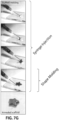
- FIGS. 2A-2C illustrate an embodiment, where the scaffold 10 is used to treat a wound site 100 formed in tissue 102 of a mammal. In certain embodiments, the scaffold 10 is used for immediate treatment of acute wounds.
- the scaffold 10 provides several benefits, including a rapid method to seal wounds 100, prevent trans-epidermal water loss, provide cells or medication(s), and enhance the healing of skin wounds (e.g., surgical sites, burn wounds, ulcers) to provide more natural tissue development (e.g., avoiding the formation of scar tissue).
- a rapid method to seal wounds 100 prevent trans-epidermal water loss, provide cells or medication(s), and enhance the healing of skin wounds (e.g., surgical sites, burn wounds, ulcers) to provide more natural tissue development (e.g., avoiding the formation of scar tissue).
- One particular benefit of the scaffold 10 is the ability of the scaffold 10 to reduce or minimize the formation of scar tissue.
- the scaffold 10 provides a more effective alternative to tissue glues and other current injectable tissue fillers and adhesives.
- microgel particles 12 are delivered to the wound site 100 followed by the initiation of the annealing reaction to anneal the microgel particles 12 to one another to form the scaffold 10.
- the wound site 100 is sealed by the scaffold 10 and as time progresses, the wound site 100 is healed into normal tissue (see also FIG. 11 ).
- FIG. 2B illustrates how adjacent microgel particles 12 (particle A and particle B) undergo chemical or enzymatic initiation of the annealing reaction to form an annealing surface 17 between microgel particles 12.
- FIG. 2C illustrates a magnified view illustrating how the scaffold 10 acts as a structural support yet permits the tissue infiltration and biomaterial resorption due to the porous nature of the scaffold 10.
- a cell 106 is illustrated infiltrating the interstitial spaces formed within the scaffold 10.
- the scaffold 10 may also be used in a regenerative capacity, for example, applied to tissue for burns, acute and chronic wounds, and the like.
- the scaffold 10 is used for chronic wounds.
- chronic wounds where the normal healing process is inhibited, the scaffold 10 can be used not only to seal wounds, but also to remove excess moisture, and apply medication(s), including cellular therapies that can assist in promoting the normal wound healing process.
- injection of the microgel particles 12 directly into the dermis via needle or cannula may be used to improve tissue contour, tissue loss, or tissue displacement.
- cells used in regenerative medicine can grow within the microgel particles 12
- cells e.g., mesenchymal stem cells, fibroblasts, etc.
- cells may be included as a therapy by initially polymerizing the cells (1-20 cells) within microgel particles, or cells may be initially adhered to microgel particles, or cells may be introduced with the microgel particle solution (non-adhered), prior to annealing in situ in tissue.
- the scaffold 10 may also be used for in vitro tissue growth, three-dimensional (3D) matrices for biological science studies, and cosmetic and dermatologic applications.
- cancer cells could be seeded along with the microgel precursors and once annealed could allow for rapid 3D growth of tumor spheroids for more physiologically-relevant drug testing without the need for matrix degradation as would be required for other 3D culture gels ( e.g., Matrigel ® ). It is expected that the rapid ability to form contacts between cells in the 3D matrix of the annealed gel will enhance growth and formation of micro-tissues from a single cell type or multiple cell types which can be used to screen for drugs or test cosmetics.
- Epidermal layers can form over the surface of a scaffold 10, which could allow testing of drugs or cosmetics on a more skin-like substitute compared to animal models.
- Previous 3D culture materials either can enable cell seeding within the gel uniformly through the volume, but not maintain cell-cell contacts because of the lack of porosity, or create porosity but require cells to be seeded following fabrication and migrate into the scaffold.
- the precursor materials prior to final annealing is flowable and can be delivered as paste, slurry, or even injected to the delivery site of interest.
- Other injectable hydrogels can provide a scaffold for in situ tissue regrowth and regeneration, however these injected materials require gel degradation prior to tissue reformation limiting their ability to provide physical support.
- the injectable microporous gel system described herein circumvents this challenge by providing an interconnected microporous network for simultaneous tissue reformation and material degradation.
- Microfluidic formation enables substantially monodisperse microgel particles 12 to form into an interconnected microporous annealed particle scaffold 10 (in one aspect of the subject matter described herein), thereby enabling the controlled chemical, physical, and geometric properties of the microgel particles 12 (e.g., building blocks), to provide downstream control of the physical and chemical properties of the assembled scaffold 10.
- the injectable gel system that forms the scaffold 10 facilitates cell migration resulting in rapid cutaneous tissue regeneration and tissue structure formation within five (5) days.
- the combination of microporosity and injectability achieved with the scaffolds 10 enables novel routes to tissue regeneration in vivo and tissue creation de novo.
- FIG. 2A illustrates the scaffold 10 formed within a wound site 100.
- Successful materials for tissue regeneration benefit from precisely matching the rate of material degradation to tissue development. If degradation occurs too quickly then insufficient scaffolding will remain to support tissue ingrowth. Conversely, a rate that is too slow will prevent proper tissue development and can promote fibrosis and/or immune rejection.
- Tuning of degradation rates based on local environment has been approached using hydrolytically and enzymatically degradable materials.
- decoupling loss of material mechanical stability with cellular infiltration has proven extremely challenging. Promotion of cellular infiltration into the material can also be approached using a lightly crosslinked matrix, however this often results in mechanical mismatch with surrounding tissues and poor material stability.
- the hydrogel degradation rate can be tuned by altering the polymeric backbone identity or crosslinking density, matching the rates of degradation and tissue formation.
- these techniques can be tuned to address specific applications of injectable hydrogels, they do not provide a robust pathway to achieve bulk tissue integration that does not rely on loss of material stability.
- microporous gel system and the resulting scaffold 10 that is created as described herein circumvents the need for material degradation prior to tissue ingrowth by providing a stably linked interconnected network of micropores for cell migration and bulk integration with surrounding tissue.
- the microporous gel system achieves these favorable features by, according to one embodiment, using the self-assembly of microgel particles 12 as "building blocks” or "sub-units" formed by microfluidic water-in-oil droplet segmentation.
- the microgel particles 12 formed in this manner are substantially monodisperse.
- the microgel particles 12 can be injected and molded into any desired shape. Lattices of microgel particles 12 are then annealed to one another via surface functionalities to form an interconnected microporous scaffold 10 either with or without cells present in the interconnected porous networks.
- the scaffold 10 preferably, in one embodiment, includes covalently linked microgel particles 12 that form a three-dimensional scaffolding 10 for tissue regeneration and ingrowth.
- the microporous gel system provides an ideal biomaterial scaffold for efficient cellular network formation in vitro and bulk tissue integration in vivo.
- the modular microporous gel system also provides mechanical support for rapid cell migration, molecular cues to direct cell adhesion, and resorption during and after tissue regeneration.
- the chemical, physical, and geometric properties of the microgel particles 12 can be predictably and uniformly tailored, allowing for downstream control of the properties of the emergent scaffolds 10.
- novel building block-based approach in which robustly achieved imperfect self-assembly is desirable to achieve microporosity fundamentally changes the use and implementation of hydrogels as tissue mimetic constructs, providing a philosophical change in the approach to injectable scaffolding for bulk tissue integration.
- the microporous gel system uses microgel particles 12 having diameter dimensions within the range from about 5 ⁇ m to about 1,000 ⁇ m.
- the microgel particles 12 may be made from polypropylene glycol)
- a polymeric network and/or any other support network capable of forming a solid hydrogel construct may be used.
- Suitable support materials for most tissue engineering/regenerative medicine applications are generally biocompatible and preferably biodegradable.
- suitable biocompatible and biodegradable supports include: natural polymeric carbohydrates and their synthetically modified, crosslinked, or substituted derivatives, such as gelatin, agar, agarose, crosslinked alginic acid, chitin, substituted and cross-linked guar gums, cellulose esters, especially with nitrous acids and carboxylic acids, mixed cellulose esters, and cellulose ethers; natural polymers containing nitrogen, such as proteins and derivatives, including cross-linked or modified gelatins, and keratins; vinyl polymers such as poly(ethyleneglycol)acrylate/methacrylate/vinyl sulfone/maleimide/norbornene/allyl, polyacrylamides, polymethacrylates, copolymers and terpolymers of the above polycondensates, such as polyesters, polyamides, and other polymers, such as polyurethanes; and mixtures or copolymers of the above classes, such as graft copolymers obtained by initializing polymerization of
- biocompatible and biodegradable polymers are available for use in therapeutic applications; examples include: polycaprolactone, polyglycolide, polylactide, poly(lactic-co-glycolic acid) (PLGA), and poly-3-hydroxybutyrate. Methods for making networks from such materials are well-known.
- the microgel particles 12 further include covalently attached chemicals or molecules that act as signaling modifications that are formed during microgel particle 12 formation.
- Signaling modifications includes the addition of, for example, adhesive peptides, extracellular matrix (ECM) proteins, and the like.
- Functional groups and/or linkers can also be added to the microgel particles 12 following their formation through either covalent methods or non-covalent interactions (e.g., electrostatic charge-charge interactions or diffusion limited sequestration).
- Crosslinkers are selected depending on the desired degradation characteristic. For example, crosslinkers for the microgel particles 12 may be degraded hydrolytically, enzymatically, photolytically, or the like. According to the invention, the crosslinker is a matrix metalloprotease (MMP)-degradable crosslinker.
- MMP matrix metalloprotease
- crosslinkers are synthetically manufactured or naturally isolated peptides with sequences corresponding to MMP-1 target substrate, MMP-2 target substrate, MMP-9 target substrate, random sequences, Omi target sequences, Heat-Shock Protein target sequences, and any of these listed sequences with all or some amino acids being D chirality or L chirality.
- the crosslinker sequences are hydrolytically degradable natural and synthetic polymers consisting of the same backbones listed above (e.g., heparin, alginate, poly(ethyleneglycol), polyacrylamides, polymethacrylates, copolymers and terpolymers of the listed polycondensates, such as polyesters, polyamides, and other polymers, such as polyurethanes).
- the crosslinkers are synthetically manufactured or naturally isolated DNA oligos with sequences corresponding to: restriction enzyme recognition sequences, CpG motifs, Zinc finger motifs, CRISPR or Cas-9 sequences, Talon recognition sequences, and transcription factor-binding domains.
- any of the crosslinkers from the listed embodiments one are activated on each end by a reactive group, defined as a chemical group allowing the crosslinker to participate in the crosslinking reaction to form a polymer network or gel, where these functionalities can include: cysteine amino acids, synthetic and naturally occurring thiol-containing molecules, carbene-containing groups, activated esters, acrylates, norborenes, primary amines, hydrazides, phosphenes, azides, epoxy-containing groups, SANPAH containing groups, and diazirine containing groups.
- a reactive group defined as a chemical group allowing the crosslinker to participate in the crosslinking reaction to form a polymer network or gel
- these functionalities can include: cysteine amino acids, synthetic and naturally occurring thiol-containing molecules, carbene-containing groups, activated esters, acrylates, norborenes, primary amines, hydrazides, phosphenes, azides, epoxy-containing groups, SANPA
- the chemistry used to generate microgel particles 12 allows for subsequent annealing and scaffold 10 formation through radically-initiated polymerization.
- This includes chemical-initiators such as ammonium persulfate combined with Tetramethylethylenediamine.
- photoinitators such as Irgacure ® 2959 or Eosin Y together with a free radical transfer agent such as a free thiol group (used at a concentration within the range of 10 ⁇ M to 1 mM) may be used in combination with a light source that is used to initiate the reaction as described herein.
- a free thiol group may include, for example, the amino acid cysteine, as described herein.
- peptides including a free cysteine or small molecules including a free thiol may also be used.
- Another example of a free radical transfer agent includes N-Vinylpyrrolidone (NVP).
- microgel particle 12 formation chemistry allows for network formation through initiated sol-gel transitions including fibrinogen to fibrin (via addition of the catalytic enzyme thrombin).
- Functionalities that allow for particle-particle annealing are included either during or after the formation of the microgel particles 12.
- these functionalities include ⁇ , ⁇ -unsaturated carbonyl groups that can be activated for annealing through either radical initiated reaction with ⁇ , ⁇ -unsaturated carbonyl groups on adjacent particles or Michael and pseudo-Michael addition reactions with nucleophilic functionalities that are either presented exogenously as a multifunctional linker between particles or as functional groups present on adjacent particles.
- This method can use multiple microgel particle 12 population types that when mixed form a scaffold 10.
- microgel particle 12 of type X presenting, for example, nucleophilic surface groups
- microgel particle 12 type Y presenting, for example, ⁇ , ⁇ -unsaturated carbonyl groups.
- functionalities that participate in Click chemistry can be included allowing for attachment either directly to adjacent microgel particles 12 that present complimentary Click functionalities or via an exogenously presented multifunctional molecule that participates or initiates ( e.g., copper) Click reactions.
- the annealing functionality can include any previously discussed functionality used for microgel crosslinking that is either orthogonal or similar (if potential reactive groups remain) in terms of its initiation conditions (e.g., temperature, light, pH) compared to the initial crosslinking reaction.
- initiation conditions e.g., temperature, light, pH
- the subsequent annealing functionality can be initiated through temperature or photoinitiation (e.g., Eosin Y, Irgacure ® ).
- the initial microgels may be photopolymerized at one wavelength of light (e.g., ultraviolent with Irgacure ® ), and annealing of the microgel particles 12 occurs at the same or another wavelength of light (e.g., visible with Eosin Y) or vice versa.
- annealing moieties can include non-covalent hydrophobic, guest/host interactions (e.g., cyclodextrin), hybridization between complementary nucleic acid sequences or nucleic acid mimics (e.g., protein nucleic acid) on adjoining microgel particles 12, or ionic interactions.
- An example of an ionic interaction would consist of alginate functionality on the microgel particle surfaces that are annealed with Ca2+. So-called "A+B" reactions can be used to anneal microgel particles 12 as well.
- A+B reactions can be used to anneal microgel particles 12 as well.
- two separate microgel types are mixed in various ratios (between 0.01: 1 and 1: 100 A:B) and the surface functionalities of type A react with type B (and vice versa) to initiate annealing.
- reaction types may fall under any of the mechanisms listed herein.
- the microgel particles 12 may be fabricated using either microfluidic or millifluidic methods, generating deterministic microgel particle length scales with small variability and in high throughput (e.g., frequencies greater than 10 particles/second).
- the coefficient of variation of the microgel particle 12 length scale e.g., diameter
- Milli- or microfluidics allow for uniform, pre-determined, concise material properties to be included pre-, in-, and post-formation of microgel particles 12.
- the microfluidic/millifluidic production mechanism allows for ease of scaling-up production as well as good quality control over chemical composition and physical characteristics of the microgel particles 12.
- the millifluidic and/or microfluidic technologies for microgel particle 12 generation are easily scalable processes to create large amounts of material for commercial needs, while maintaining high accuracy and precision in microgel particle 12 characteristics. Moreover, this is all accomplished at low cost in comparison to other technologies involving electrospinning or large-scale fibrin purification.
- the microgel particles 12 may be formed using automated fluidic methods relying on water-in-oil emulsion generation. This includes microfluidic or millifluidic methods utilizing glass/PDMS, PDMS/PDMS, glass/glass, or molded/cast/embossed plastic chips to create water in oil droplets with a size distribution variation that is less than 35%.
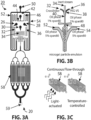
- FIGS. 3A-3F illustrates a microfluidic device 20 that is used to generate the microgel particles 12.
- the microfluidic device 20 is formed in a substrate material 22 such as PDMS which may include another substrate material 24 ( e.g., glass) that is bonded the substrate 22.
- the microfluidic device 20 includes a first inlet 26, a second inlet 28, and a third inlet 30. As seen in FIG. 3A , the third inlet 30 is interposed between the first inlet 26 and the second inlet 28.
- the first inlet 26 is coupled to a solution containing a 4-arm poly(ethylene glycol) vinyl sulfone (PEG-VS) backbone (20 kDa) that has been pre-modified with oligopeptides for cell adhesive properties (e.g., RGD) and surface/tissue annealing functionalities (e.g., K and Q peptides).
- PEG-VS poly(ethylene glycol) vinyl sulfone
- the PEG-VS backbone may be prefunctionalized with 500 ⁇ M K-peptide (Ac-FKGGERCG-NH 2 [SEQ ID NO: 1]) (Genscript), 500 ⁇ M Q-peptide (Ac-NQEQVSPLGGERCG-NH 2 [SEQ ID NO: 2]), and 1 mM RGD (Ac-RGDSPGERCG-NH 2 [SEQ ID NO: 3]) (Genscript).
- the solution input to the first inlet 26 may contain about 5% (on a weight basis) modified PEG-VS contained in a buffer of 0.3 M triethanolamine (Sigma), pH 8.25.
- the second inlet 28 is coupled to a solution containing the crosslinker, which in one embodiment, is an 12mM di-cysteine modified Matrix Metallo-protease (MMP) (Ac-GCRDGPQGIWGQDRCG-NH 2 [SEQ ID NO: 4]) substrate (Genscript).
- MMP Matrix Metallo-protease
- the MMP substrate was pre-reacted with 10 ⁇ M Alexa-fluor 647-maleimide (Life Technologies). Of course, in practical applications, the use of the fluorescent probe is not needed. All solutions can be sterile filtered through a 0.2 ⁇ m Polyethersulfone (PES) membrane in a Luer-lock syringe filter.
- PES Polyethersulfone
- K-peptides refer to those peptides that contain therein a Factor XIIIa recognized lysine group.
- Q-peptides refer to those peptides that contain therein a Factor XIIIa recognized glutamine group.
- peptide sequences beyond those specifically mentioned above may be used. The same applies to the RGD peptide sequence that is listed above.
- the third inlet 30 is coupled to an aqueous solution containing 5% by weight of PEG-VS (unmodified by K, Q, or RGD peptides).
- the aqueous PEG-VS solution is preferably viscosity-matched with the PEG-VS solution introduced via the first inlet 26 and can be used to control the pH of the crosslinker solution and to inhibit crosslinking until droplet formation.
- the aqueous PEG-VS solution acts as a barrier that prevents any material diffusive mixing of reactive solutions upstream of the droplet generation region. This significantly increases the lifespan of the device before fouling occurs.
- 3E and 3F illustrate how the inert liquid solution prevents mixing of left and right solutions prior to droplet segmentation. Note that the method of making the microgel particles 12 will also work with omitting the third inlet 30, and adjusting peptide/crosslinker concentrations accordingly, yet the lifespan of the device will not be as long.
- the first inlet 26, second inlet 28, and third inlet 30 are connected to, respectively, channels 32, 34, 36.
- the channels intersect at junction 38 and are carried in a common channel 40.
- the fourth inlet 42 is provided in the device and is coupled to an oil phase that contains a surfactant (e.g., 1% SPAN ® 80 by volume although other surfactants can be used).
- the fourth inlet 42 is connected to two channels 44, 46 that intersect at junction 48 at a downstream region of the common channel 40.
- the junction 48 in the device 20 is where the aqueous-based droplets are formed that include the PEG-VS component and the crosslinker.
- a fifth inlet 50 is provided that is coupled to another oil phase that contains a surfactant at a higher volumetric percentage than that connected to the fourth inlet 42.
- the fifth inlet 50 can be connected to an oil phase containing 5% SPAN ® 80 by volume. Again, other surfactants besides SPAN ® 80 could also be used.
- the fifth inlet 50 is connected to two channels 52, 54 that intersect at junction 56 in a pinching orientation as illustrated.
- the common channel 40 continues to a series of progressively branching branch channels 58.
- the branch channels 58 permit continuous flow of the microgel particles 12 through individual parallel channels where local environmental conditions can be optionally controlled. For example, temperature of the individual branch channels 58 can be controlled to regulate crosslinking conditions for the microgel particles 12. Likewise, the branch channels 58 may be illuminated with light to control light-activated reactions. The microgel particles 12 may be removed from the device 20 using the outlet 59. It should be understood, however, that regulation of the temperature of the branch channels 58 or the use of light activation is entirely optional as the crosslinking reaction may occur just through the passage of time when the device is operated at or around ambient temperatures.
- the first inlet 26, second inlet 28, third inlet 30, fourth inlet 42, and fifth inlet 50 are connected, respectively, to fluid lines 26', 28', 30', 42', and 50' that connect to a pumping device 51 or multiple pumping devices 51 that pumps respective fluids into the correspondingly connected inlets 28, 28, 30, 42, 50.
- the pumping device 51 may include separate pumps tied to each different fluid. Examples of types of pumps that may be used include syringe pumps or other pumps commonly used in connection with microfluidic devices.
- the pumping device 51 uses regulated pressurized gas above a fluid reservoir to pump fluid at the desired flow rate(s) through the device.
- FIGS. 4A-4C illustrate an alternative microfluidic device 60 that is used to generate the microgel particles 12.
- the microfluidic device 60 includes first inlet 62, a second inlet 64, a third inlet 66, and a fourth inlet 68.
- the first inlet 62 is coupled to a modified PEG-VS source such as that described above.
- the second inlet 64 is coupled to a crosslinking agent.
- the third inlet 66 is coupled to a source containing oil and a surfactant.
- the fourth inlet 68 is coupled to a source containing oil and a surfactant at a higher concentration than that coupled to the third inlet 66.
- the first inlet 62 and the second inlet 64 are coupled to respective channels 70, 72 that lead to a common channel 74.
- the third inlet 66 is coupled to a pair of channels 76, 78 that intersect with the common channel 74 at a junction 80 (best seen in FIG. 4B ) where droplet generation occurs (droplets will form the microgel particles 12 upon reaction).
- the fourth inlet 68 is coupled to a pair of channels 82, 84 that intersect with the common channel 74 at a downstream location 86 (best seen in FIG. 4B ) with respect to junction 80. As seen in FIG.
- the device 60 includes a series of progressively branching branch channels 88 which are similar to those described in the context of the embodiment of FIGS. 3A-3C .
- Microgel particles 12 passing through branch channels 88 may collected in a collection chamber 90 or the like which can be removed from the device 60.
- Fluid is delivered to the device 60 using fluid lines and a pumping device as described previously in the context of the embodiment of FIGS. 3A-3C .
- the fluidic conditions that lead to microgel particle 12 formation include, in one embodiment, on-chip mixing of a PEG-based and crosslinker-based aqueous solutions, where one part contains base polymer and the other contains the crosslinking or initiating agent.
- a PEG-based and crosslinker-based aqueous solutions where one part contains base polymer and the other contains the crosslinking or initiating agent.
- FIGS. 3A-3C there is a three-input mixing which includes the aforementioned components plus the addition of the aqueous-based inert stream.
- These PEG and crosslinker solutions are mixed at either a 1:1 volumetric ratio, or another controllable ratio (controlled by relative flow rates into the device) up to 1:100.
- the ratios of the oil and total aqueous flow rates are controlled to determine a specific size microgel particle 12, where these ratios can range from 4: 1 (aqueous: oil) down to 1:10 (aqueous:oil).
- the chip device 20 is designed to have three aqueous-based solutions combined to form the microgel particles 12, wherein the base polymer and crosslinking/initiating agent are separated by a non-reactive solution upstream of the droplet generator to prevent reaction of solutions and fouling of the chip over time in the region upstream of droplet generation.
- the portion of non-reactive solution should be equal to or less than base and cross-linker solutions, from 1 to 0.05 times of the volume rate of the other solutions. This embodiment can thus improve the reliability and lifetime of chips used for microgel generation.
- cells can be introduced into either of the two or three introduced aqueous solutions to enable encapsulation of these cells (single cells or clusters of 2-20 cells per particle) within microgel particles 12 such that encapsulated cells can produce factors to enhance wound healing or cell ingrowth.
- FIGS. 3A-3D and 4A-4C illustrate different microfluidic devices 20, 60 that may be used to generate the microgel particles 12.
- the microfluidic flow path may include a 'T-junction' architecture such as that illustrated in FIG. 5 .
- the microfluidic device 92 includes a junction formed between a first channel 94 that carries the aqueous phase while a second channel 96 includes the oil phase. Droplets 97 are formed and carried via an outlet channel 98 (which may be the same as the first or second channels 94, 96). Alternatively, different droplet formation configurations may be used to generate the microgel particles 12.
- the device may generate droplets 97 using the gradient of confinement due to non-parallel top and bottom walls such as that disclosed in Dangla et al., Droplet microfluidics driven by gradients of confinement, Proc Natl Acad Sci USA, 110(3): 853-858 (2013 ).
- the channel surfaces should be modified such that the aqueous phase is non-wetting, which can include a fluorination of the surface, or converting the surfaces to become hydrophobic or fluorophilic, either by a covalent silane-based treatment or another non-specific adsorption based approach.
- a plastic polymer containing fluorophilic groups comprises the chip material and can be combined with the previously mentioned surface coatings or without a surface coating.
- the oil used in the preferred embodiment should be either a mineral oil (paraffin oil) supplemented with a non-ionic surfactant, vegetable oil supplemented with an ionic surfactant, or a fluorinated oil supplemented with a fluorinated surfactant (or any combination of these two oil/surfactant systems).
- mineral oil paraffin oil
- vegetable oil supplemented with an ionic surfactant
- fluorinated oil supplemented with a fluorinated surfactant (or any combination of these two oil/surfactant systems).
- a preferred embodiment of the microfluidic system for microgel particle 12 generation includes a low concentration of surfactant in the initial pinching oil flow (1% or less) that creates droplets followed by addition of an oil + surfactant solution from a separate inlet that is merged with the formed droplet and oil solution and contains a higher level of surfactant (up to 10 times or even 50 times higher than the initial surfactant). This is illustrated, for example, in the embodiments of FIGS. 3A-3D and 4A-4C .
- the two oil pinching flows have the same concentration of surfactant.
- there is not a second pinching oil flow and only the flow-focusing oil flow to generate droplets.
- the t-junction droplet junction may optionally be combined with a second focusing oil inlet with equal or greater surfactant concentration.
- microgel particles 12 are extracted from the oil phase using either centrifugation through an aqueous phase, or filtration through a solid membrane filtration device. For example, filtration may be used to reduce the volume of free aqueous solution holding the microgel particles 12 (free volume). In one embodiment, the aqueous free volume is less than about 35% of the total volume.
- microgel particle generation is carried out in a milli- or microfluidic platform, generating stocks of relatively monodisperse microgel particles 12 that are then mixed at desired ratios to obtain deterministic distributions and ratios of microgel particle 12 sizes. Ratios of microgel particle 12 sizes can be controlled precisely to control pore structure, or chemical properties in a final annealed scaffold 10 with stoichiometric ratios from: 1:1, 10:1, or exceeding 100:1.
- microgel particles 12 via a water-in-oil system can also be carried out using sonic mixing methods or a rotating vortex. These latter methods generate polydisperse populations of microgel particles 12 with size ranges from 100 nanometers to 500 micrometers. These particles can then be filtered using porous filters, microfluidic filtration, or other techniques known in the art to obtain a narrower size distribution of microgel particles 12 ( e.g., coefficient of variation less than 50%).
- the component microgel particles 12 of different shapes can be fabricated using stop flow lithography, continuous flow lithography, and other methods to create shaped particles that rely on shaping flows (see Amini et al. International Publication No.
- microgel particles 12 are non-spherical with long and short dimensions that can vary between 5 and 1000 micrometers.
- Shaped particles can also be fabricated by generating spherical particles in a water in oil emulsion, followed by extrusion of said particles through microfabricated constrictions that have length scales smaller than the diameter of the particle.
- the previously spherical particles adopt the shape of the constriction as they transition to a gel and retain that shape as they gel in the constriction by any of the crosslinker reactions listed above. The gels retain that shape after exiting the microfabricated construction.
- Shaped particles can allow for additional control of pores, overall porosity, tortuosity of pores, and improved adhesion within the final scaffold formed by microgel particle 12 annealing.
- the microgel particles 12 are either modified covalently or not (e.g., inclusion spatially within by diffusion) to provide biologically active molecules (e.g., small molecule drugs, antibiotics, peptides, proteins, steroids, matrix polymers, growth factors, antigens, antibodies, etc.).
- biologically active molecules e.g., small molecule drugs, antibiotics, peptides, proteins, steroids, matrix polymers, growth factors, antigens, antibodies, etc.
- Inclusion of signaling molecules after formation of the microgel particle 12 may be accomplished through passive diffusion, surface immobilization (permanent or temporary), and/or bulk immobilization (permanent or temporary).
- nanoparticles are included in the initial pre-polymer solution and incorporated in the microgel particles 12 during initial polymerization or gelation, and the nanoparticles may include biologically active molecules for sustained or rapid release and delivery.
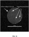
- microgel particles 12 containing free primary amines can be modified with NHS-Azide.
- To this set of microgel particles 12 can be added a protein modified with a NHS-phosphine, resulting in surface-coating of the microgel particles 12 with the modified protein.
- FIG. 10 illustrates an embodiment in which a microgel particle 12 has nanoparticles embedded therein and a surface that has been modified with a protein using Click chemistry.
- the microgel particles 12 (which can be a homogeneous or heterogeneous mixture) may be applied to a desired location ( in vitro, in situ, in vivo ) .
- the desired location on mammalian tissue 102 can include, for example, a wound site 100 or other site of damaged tissue.
- the microgel particles 12 can be introduced alone in an aqueous isotonic saline solution or slurry (with preferably 30-99 % volume fraction of microgel particles 12, and less preferably 1-30 % volume fraction).
- microgel particles 12 can be introduced along with cells as single-cells or aggregates with cell to particle ratios from 10:1 to create dense cell networks within the final annealed scaffold 10 or 1:100 or even 1: 1000 to create sparsely seeded scaffolds 10 with cells that produce soluble factors useful for regeneration.
- microgel particles 12 can be cultured with cells at a low volume fraction of particles ( ⁇ 10%) for a period of time in cell-permissive media to promote adhesion to the individual microgel particles 12.
- These composite cell-adhered microgel particles 12 can be introduced as the active component that would anneal to form a microporous cell-seeded scaffold 10, which may be beneficial to enhance the speed of regenerative activity.
- microgel particles 12 Desired in vitro locations to introduce microgel particles 12 include well plates (e.g., 6-well, 96-well, 384-well) or microfluidic devices to form 3D microporous culture environments for cells following annealing, and enable subsequent biological assays or high-throughput screening assays with more physiologically-relevant 3D or multi-cellular conditions.
- microgel particle 12 solutions can be pipetted into wells or introduced via syringe injection followed by introduction of an annealing solution or triggering of annealing photochemically.
- a solution of microgel particle 12 solution could be mixed with a slow acting annealing solution (annealing occurring over 10-30 min) before delivery.
- In situ locations include external wound sites (e.g., cuts, blisters, sores, pressure ulcers, venous ulcers, diabetic ulcers, chronic vascular ulcers, donor skin graft sites, post-Moh's surgery sites, post-laser surgery sites, podiatric wounds, wound dehiscence, abrasions, lacerations, second or third degree burns, radiation injury, skin tears and draining wounds, etc.).
- external wound sites e.g., cuts, blisters, sores, pressure ulcers, venous ulcers, diabetic ulcers, chronic vascular ulcers, donor skin graft sites, post-Moh's surgery sites, post-laser surgery sites, podiatric wounds, wound dehiscence, abrasions, lacerations, second or third degree burns, radiation injury, skin tears and draining wounds, etc.
- the microgel particle solution may be used to heal other epithelial surfaces (i.e., urothelial (bladder and kidney), aerodigestive (lung, gastrointestinal), similarly to skin epithelium (i.e ., stomach or duodenal ulcer; following penetrating trauma to the lung, bladder or intestinal fistulas, etc.). Additionally, the microgel particle solution can be applied to other tissues through a catheter or cannula, such as nervous tissue and cardiac tissue where tissue ingrowth would be beneficial to prevent scarring and to facilitate regenerative healing following injury, such as after spinal cord trauma, cerebral infarction/stroke, and myocardial infarction.
- urothelial bladedder and kidney
- aerodigestive lung, gastrointestinal
- skin epithelium i.e ., stomach or duodenal ulcer
- the microgel particle solution can be applied to other tissues through a catheter or cannula, such as nervous tissue and cardiac tissue where tissue ingrowth would be beneficial to prevent scarring and to facilitate regenerative healing following
- microgel particle containing solution can be stored separately from an annealing solution and be mixed during introduction (a method analogous to epoxy adhesives) to prevent premature initiation of the annealing reaction before entry into a wound site 100.
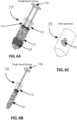
- FIG. 6A illustrates one such embodiment of a delivery device 110 that includes a first barrel 112, a second barrel 114, and a plunger 116 that is used to dispense the solution containing the microgel particles 12 from each barrel 112, 114.
- the first barrel 112 contains microgel particles 12 and thrombin at a concentration ranging from 0.1 to 5 U/ml and the second barrel 114 contains the microgel particles 12 and FXIII at a concentration of 0.1 to 1,000 U/ml).
- both barrels 112, 114 there is a 1 to 1 volume fraction of K and Q peptide containing microgel particles 12 where the concentration of K and Q peptides range from 10 - 1,000 ⁇ M in the microgel particles 12.
- the thrombin upon mixing the thrombin activates the FXIII (to form FXIIIa) and the resultant FXIIIa is responsible for surface annealing and linking of the K and Q peptides on the adjacent microgel particles 12.
- the two barrels 112, 114 can contain two separate microgel particle 12 types with annealing moieties that require the combination to initiate cross-linking.
- An alternative storage and delivery method would be in a single barrel syringe 110 as illustrated in FIG. 6B or a multi-use or single-use compressible tube as illustrated in FIG. 6C (e.g., similar to toothpaste or antibiotic ointment) in which the microgel particle slurry can be squeezed out to a desired volume and spread over the wound site 100 and then annealed through exposure to light, where the active agent for photochemistry is Eosin-Y at a concentration of 100 ⁇ M although concentrations within the range of 10 ⁇ M - 1 mM will also work.
- Eosin-Y is accompanied with a radical transfer agent which can be, for example, a chemical species with a free thiol group.
- a radical transfer agent includes cysteine or peptides including cysteine(s) described herein ( e.g., used at a concentration of 500 ⁇ M).
- the light should be delivered via a wide spectrum white light (incandescent or LED), or a green or blue LED light. A flashlight, wand, lamp, or even ambient light may be used to supply the white light. Exposure should occur between 0.1 seconds and 1000 seconds, and the intensity of light should range between 0.01 mW/cm 2 to 100 mW/cm 2 at the site of annealing.
- light-mediated annealing can be accomplished using a UV light (wavelengths between 300 - 450 nm), where the agent for photochemistry is IRGACURE ® 2959, at a concentration of 0.01% w/v to 10% w/v.
- the exposure time should be between 0.1 seconds and 100 seconds, with a light intensity of 0.1 mW/cm 2 to 100 mW/cm 2 at a site of annealing.
- microgel precursors 12 would be stored in opaque (opaque with respect to wavelength range that initiates annealing) syringe or squeeze tubes 110 containers prior to use.
- Desired in situ locations include internal cuts and tissue gaps (e.g., from surgical incisions or resections), burn wounds, radiation wounds and ulcers, or in cosmetic surgery applications to fill the tissue location and encourage tissue ingrowth and regeneration rather than the fibrotic processes common to contemporary injectables.
- the microgel particle slurry can be spread using a sterile applicator to be flush with the wound or mounded within and around the wound site 100 (within the wound and 2 mm to 1 cm beyond the original wound extents) to create an annealed scaffold that extends beyond the wound site 100 or tissue defect to provide additional protection, moisture, and structure to support tissue regeneration.
- An annealing process is initiated through the application of a stimulus (e.g., radical initiator, enzyme, Michael addition, etc.) or through interactions with a stimulus that is already present at the site of application of the microgel particles 12 that interacts with functional groups on the surface of the microgel particles 12, forming a solid contiguous highly porous scaffold 10 formed from the annealed (linked) microgel particles 12.
- a stimulus e.g., radical initiator, enzyme, Michael addition, etc.
- the annealing process can allow for fusion of the scaffold 10 to the surrounding tissue, providing an effective seal, a local medication and/or cell delivery device, a vascularized scaffold for in vivo sensing, and a better path to tissue regeneration.
- the annealing process allows for on-site/on-demand gel formation (which is ideal for in vitro and in vivo applications), for example delivery through a small incision to a minimally-invasive surgical site or through injection by a needle or through a catheter or cannula.
- the scaffold 12 may comprise of homogeneous or heterogeneous populations of microgel particles 12.
- the heterogeneous populations of microgel particles 12 may vary in physical ( e.g., in size, shape, or stiffness) or vary in chemical composition ( e.g., varied ratios of degradable linkers, or L- or D- amino acids to modify degradation rate, varied annealing moieties, cell adhesive moieties, or loading of microgels 12 with bioactive molecules or nanoparticles).
- the heterogeneous composition of the final annealed scaffold 10 can be random or structured in layers of uniform composition to create gradients in micro-porous structures (by varying microgel particle 12 sizes in layers, for example) or gradients of chemical composition (by layers of microgel particles 12 with different composition or bio-active molecule loading). Gradients may be useful in directing cell ingrowth and tissue regeneration in vivo, or development of tissue structures in vitro. Gradients in microgel particle 12 composition could be achieved by delivering sequential slurries of a gel of a single composition, followed by annealing, and then subsequent delivery of the next gel of a second composition, followed by annealing which links the new layer of microgels to the previous layer, until a desired number of layers have been accumulated.
- each layer can be controlled using the volume of slurry injected and area of the injection site.
- An alternative embodiment to achieve gradients is to load a multi-barrel syringe applicator such as that illustrated in FIG. 6A with different microgel compositions in each of the barrels. Each of the barrels are simultaneously compressed and feed to the nozzle 120 in layered sheets.
- the nozzle 120 itself of the syringe applicator can be non-circular or rectangular to create a layered slurry of multiple composition that is injected to a site in a ribbon-like structure, which can then be annealed in this arrangement. Formation of the structurally contiguous annealed scaffold 10 may be achieved through radical, enzymatic or chemical (e.g., Click chemistry) processes.
- Annealing may occur through surface chemistry interactions between microgel particles 12 once they are ready to be placed at the delivery site.
- the process occurs through radical-initiated annealing via surface polymerizable groups (e.g., radical initiation by photosensitive radical initiators, etc.).
- the process occurs through enzymatic chemistry via surface presented enzymatically-active substrates (e.g., transglutaminase enzymes like Factor XIIIa).
- the process occurs through covalent coupling via Michael and pseudo-Michael addition reactions.
- This method can use multiple microgel particle population types that when mixed form a solid scaffold 10 (e.g., microgel particle 12 type A presenting, for example, nucleophilic surface groups and microgel particle 12 type B presenting, for example, ⁇ , ⁇ -unsaturated carbonyl groups).
- the process occurs through Click chemistry attachment.
- this method can use heterogeneous microgel particle 12 populations that when mixed form a solid microporous gel.
- annealing may be achieved using light (for example, either white light or UV light) to initiate a chemical reaction between molecules on the gel surfaces, mediated by a light activated molecule in solution in and around (or directly covalently liked to) the microgels as described herein.
- the microgel particles 12 include a PEG based polymeric backbone in combination with an enzymatically degradable crosslinker to allow for bioresorbability.
- the PEG-based polymeric backbone is a 4-arm poly(ethylene glycol) vinyl sulfone (PEG-VS) backbone pre-modified with oligopeptides for cell adhesive properties (e.g., RGD) and surface annealing functionalities (e.g., K and Q peptides) and the cross-linker is a matrix metalloprotease (MMP)-degradable cross-linker.
- PEG-based polymeric backbone is a 4-arm poly(ethylene glycol) vinyl sulfone (PEG-VS) backbone pre-modified with oligopeptides for cell adhesive properties (e.g., RGD) and surface annealing functionalities (e.g., K and Q peptides)
- MMP matrix metalloprotease
- microgel particles 12 are formed by a water-in-oil emulsion. Gelation of the microgel particles 12 occurs upon combination of PEG solution with cross-linker solution (followed shortly by partitioning into microgel droplets before completion of gelation). A variety of substrates, including peptide ligands, can be further added for enhanced bioactivity. In one embodiment, scaffold formation is accomplished by addition and activation of radical photo-initiator to the purified microgel particles 12 to induce chemical cross-linking.
- scaffold formation is accomplished by the use and/or activation of an endogenously present or exogenously applied transglutaminase enzyme, Factor XIII, to the purified microgel particles 12 that have been modified with two peptide ligands either pre-formation, during formation, or post-formation to induce enzymatic cross-linking.
- scaffold formation is accomplished using a combination of the aforementioned radical and enzymatic methods.
- porous scaffolds provide for greater access for live cells due to the freedom of movement through the pores (i.e., not requiring degradation to allow penetration like all current and previous non-porous and nano-porous scaffolds).
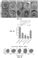
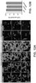
- FIG. 7B shows that when implanting and annealing a scaffold 10 in a skin wound in vivo, significantly enhanced cell invasion and tissue-structure in growth was observed after 5 days when compared to a non-porous gel of the same material as seen in FIGS. 7B.
- FIG. 7A illustrates H&E staining of tissue sections in SKH1-Hr hr mice for tissue injected with the scaffold 10 (identified as MAP scaffold) as well as the non-porous control 24 hours after injection.
- FIG. 7C illustrate representative images of wound closure during a 5 day in vivo wound healing model in SKH1-Hr hr mice.
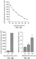
- FIG. 7D illustrates representative images of wound closure during 7 day in vivo BALB/c mice experiments.
- FIG. 7E illustrates wound closure quantification data from BALB/c in vivo wound healing.
- the scaffolds 10 promote significantly faster wound healing than the no treatment control, the non-porous PEG gel, and the gels lacking the K and Q peptides.
- Porous gels created ex vivo to precisely match the wound shape using the canonical, porogen-based, casting method showed appreciable wound healing rates, comparable to the scaffolds 10, but lacking injectability (N ⁇ 5).
- FIG. 7F illustrates traces of wound bed closure during 7 days in vivo for each treatment category corresponding to FIG. 7D .
- therapeutic agents applied to the microgel particles 12 or the scaffold 10 can be released slowly or rapidly, and the scaffold 10 has the ability to break down over a pre-determined period of time either from hydrolysis, proteolysis, or enzymolysis, depending on the intended treatment (e.g., if it is being used to treat a chronic wound, a more stable cross-linker that degrades slowly over time is used).
- the annealing quality of the microgel scaffold 10 allows the scaffold 10 to function as a tissue sealant (e.g., acute wounds, surgical closure, etc.), and the filling of different molded shapes that are clinically useful to mimic tissues.
- tissue sealant e.g., acute wounds, surgical closure, etc.
- FIGS. 6A or 6B illustrates how the microgel particle containing solution or slurry can be applied using a syringe device like that of FIGS. 6A or 6B into a treatment site where the microgel conforms to the shape of the injection site (e.g., in this case a star-shaped site) and subsequent annealing of the scaffold 10 into the star shape.
- a syringe device like that of FIGS. 6A or 6B into a treatment site where the microgel conforms to the shape of the injection site (e.g., in this case a star-shaped site) and subsequent annealing of the scaffold 10 into the star shape.
- the rate of degradation of the microgel scaffolds 10 By adjusting the rate of degradation of the microgel scaffolds 10 the scar forming or regenerative response in a wound can be modified.
- the degradation rate of the microgel scaffolds 10 was modified by using D- instead of L-amino acids in the MMP-degradable crosslinker. Adjusting the ratio of microgel particles 12 with D- or L-chirality in the crosslinker adjusted the rate of degradation in the tissue. Scaffolds 10 made from mixtures of D and L crosslinked microgels (at a 1: 1 ratio) resulted in gels present in the tissue 21 days after injection, however in the D-only gels, there was no remaining gel left after 21 days in vivo.
- FIGS. 8A-8G show the effects of scar reduction when using a 1:1 mixture of D:L, as compared directly to a no treatment wound. Dermal thickness is doubled and scar size is reduced by 25% in the 1: 1 D:L gel treatment. Additionally, six (6) times more hair follicles and sweat glands are present in the gel-treated case, compared to the no treatment case.
- a microfluidic water-in-oil emulsion approach was used to segment a continuous pre-gel aqueous phase into uniform scaffold building blocks as described herein.
- Generating microgel particles 12 as building blocks serially at the microscale, rather than using the typical vortex and sonication-based approaches allowed tight control over the formation environment and ultimate material properties of the emergent scaffold 10.
- microfluidic generation of microgel particle "building blocks" is a readily scalable process: a practical requirement for wide adoption and use.
- the resultant microgel particles 12 were composed of a completely synthetic hydrogel mesh of poly(ethylene)glycol-vinyl sulfone (PEG-VS) backbones decorated with cell-adhesive peptide (RGD [SEQ ID NO: 3]) and two transglutaminase peptide substrates (K [SEQ ID NO: 1] and Q [SEQ ID NO: 2]).
- PEG-VS poly(ethylene)glycol-vinyl sulfone
- RGD cell-adhesive peptide
- K transglutaminase peptide substrates
- the microgel particles 12 were crosslinked via Michael type addition with cysteine-terminated matrix metalloprotease-sensitive peptide sequences that allowed for cell-controlled material degradation and subsequent resorption.
- the microgel particles 12 were purified into an aqueous solution of isotonic cell culture media for storage and when used to form a gel were annealed to one another via a non-canonical amide linkage between the K and Q peptides mediated by activated Factor XIII (FXIIIa), a naturally occurring enzyme responsible for stabilizing blood clots.
- FXIIIa activated Factor XIII
- This enzyme-mediated annealing process allowed incorporation of living cells into a dynamically forming scaffold 10 that contained interconnected microporous networks.
- a slurry of the microgel particles 12 can be delivered via syringe application, ultimately solidifying in the shape of the cavity in which they are injected.
- FIG. 9A illustrates how the annealing kinetics can be altered by the adjustment of pH and temperature.
- the annealing environment chosen for this experiment was pH 8.25 and a temperature of 37°C.
- microgel particles 12 By tuning the microgel particle size and composition a diverse set of assembled scaffolds 10 were able to be generated.
- microgel particles 12 By using microgel particles 12 from 30 to 150 ⁇ m in diameter, networks with median pores diameters ranging from ⁇ 10 to ⁇ 35 ⁇ m were achieved).
- Different PEG weight percentages and crosslinker stoichiometries were screened to demonstrate a range of easily achievable storage moduli from ⁇ 10 to 1000 Pa that spans the stiffness regime necessary for mammalian soft tissue mimetics.
- FIG. 9B illustrates different hydrogel weight percentages were used to produce different stiffness materials.
- FIG. 9B illustrates different hydrogel weight percentages were used to produce different stiffness materials.
- FIG. 9C illustrates different crosslinker stoichiometries (r-ratio of crosslinker ends (-SH) to vinyl groups (-VS)) that were used to produce different stiffness values in the resultant gel.
- FIG. 9D illustrates a graph of the % degradation as a function of time for both the non-porous control as well as the inventive porous gel described herein. Degradation kinetics of particle-based, porous gel and the non-porous are shown for equal volumes of gels in vitro. The particle-based, porous gels degrade faster than non-porous gel due to higher surface area to volume ratios and faster transport through the microporous gel.
- FIG. 9E illustrates SEM images of a scaffold annealed with FXIIIa.
- FIG. 9F illustrates SEM images of microgel particles 12 without FXIIIa. Un-annealed particles are seen in FIG. 9F .
- HDF Dermal Fibroblasts
- AhMSC Adipose-derived Mesenchymal Stem Cells
- BMhMSC Bone Marrow-derived Mesenchymal Stem Cells
- Cells incorporated into the scaffold began to exhibit spread morphology 90 minutes following the onset of annealing. After two (2) days in culture, all observed cells within the scaffolds exhibited a completely spread morphology, which continued through day six (6). Importantly, an extensive network formation for all cell lines was observed by day two (2). Cell networks increased in size and complexity through the entirety of the experiment. The BMhMSCs were of particular note, as their expansive network formation and slower proliferation rate indicated that these cells were able to spread to extreme lengths, forming highly interconnected cellular networks within the microporous scaffolds.
- the scaffold was able to sustain the formation of what appeared to be a complete hair follicle with adjoining sebaceous gland within the wound bed resembling the structure of these glands in the uninjured skin.
- the scaffolds While investigating the seamless interface provided by the injectable scaffolds differences were observed in both overall and immune cell quantities at day one (1). After one (1) day post-injection, the scaffolds contained significantly higher numbers of cells within the scaffold than their non-porous bi-lateral controls. This corroborated the greater ease of cell mobility previously observed in our in vitro network formation experiments. Further, the scaffold and its surrounding tissue contained a significantly lower number of polymorphonuclear cells when compared to the non-porous bi-lateral control of the same mouse. This result indicated an overall lower initial innate immune response to the scaffolds at day one (1).
- the annealed, microgel particle-based scaffolds represent a new class of injectable biomaterial that introduces microscale interconnected porosity through robustly achieved imperfect self-assembly and annealing of individual building blocks.
- This approach allows control of micro-scale and hierarchical macro-scale properties through deterministic chemical composition and microfluidic particle generation. Both incorporated live cells and surrounding host tissue are able to immediately infiltrate the scaffold without the need for material degradation, a feat never before accomplished using injectable scaffolds.
- the injectable microgel particles completely filled the tissue void, providing a seamless boundary with the surrounding tissue.
- the interconnected microporosity of the resulting scaffold promoted cellular migration at the wound site that resulted in greater bulk integration with the surrounding tissue while eliciting a reduced host immune response, in comparison to an injectable non-porous control. Ultimately this led to faster healthy tissue reformation than with similarly comprised injectable non-porous gels.
- This gel system presents a fundamental change in the approach to bottom-up modular biomaterials by utilizing the negative space of lattice formation to promote the development of complex three-dimensional networks on time scales previously unseen using current hydrogel technologies.
- the "plug and play” nature of this strategy allows the incorporation of a wide range of already established materials (e.g., fibrin), signals (e.g., growth factors), and cell populations ( e.g., stem cells).
- Complex combinations of building blocks with deterministic chemical and physical properties may enable tissue regeneration in a range of distinct physiological niches (e.g., neural, cardiac, skin, etc.), where particle-annealed scaffolds are tailored to each niche via their building block properties.
- the unique combination of microporosity, injectability, and modular assembly inherent to scaffolds has the potential to alter the landscape of tissue regeneration in vivo and tissue creation de novo.
- Microfluidic water-in-oil droplet generators were fabricated using soft lithography as previously described. Briefly, master molds were fabricated on mechanical grade silicon wafers (University wafer) using KMPR 1025 or 1050 photoresist (Microchem). Varying channel heights were obtained by spinning photoresist at different speeds, per the manufacturer's suggestions. Devices were molded from the masters using poly(dimethyl)siloxane (PDMS) SYLGARD ® 184 kit (Dow Corning). The base and crosslinker were mixed at a 10:1 mass ratio, poured over the mold, and degassed prior to curing for 6 hours at 65 °C.
- PDMS poly(dimethyl)siloxane
- Channels were sealed by treating the PDMS mold and a glass microscope slide (VWR) with oxygen plasma at 500 mTorr and 75W for 15 seconds. Immediately after channel sealing, the channels were functionalized by injecting 100 ⁇ l of a solution of RAIN-X ® and reacting for 20 minutes at room temperature. The channels were then dried by air followed by desiccation overnight.
- VWR glass microscope slide
- Droplets were generated using a microfluidic water-in-oil segmentation system as illustrated in FIGS. 3A-3F and 4A-4C .
- the aqueous phase is a 1:1 volume mixture of two parts: (i) a 10% w/v 4arm PEG-VS (20 kDa) in 300 mM triethanolamine (Sigma), pH 8.25, prefunctionalized with 500 ⁇ M K-peptide (Ac-FKGGERCG-NH 2 [SEQ ID NO: 1]) (Genscript), 500 ⁇ M Q-peptide (Ac-NQEQVSPLGGERCG-NH 2 [SEQ ID NO: 2]), and 1 mM RGD (Ac-RGDSPGERCG-NH 2 [SEQ ID NO: 3]) (Genscript) and (ii) an 8mM (12mM for the three-inlet device) di-cysteine modified Matrix Metallo-protease (MMP) (Ac-GCRDGPQGIWGQDRCG-NH 2 [SEQ ID NO
- the microgel-in-oil mixture exited into a large (12 mm diameter, ⁇ 1 mL volume) well, where the microgel particles cured at 37 °C for a minimum of 1 hour.
- the mixture was then extracted and purified by overlaying the oil solution onto an aqueous buffer of HEPES buffered saline pH 7.4 and pelleting in a table top centrifuge at 18000 ⁇ g for 5 mins.
- the microgel-based pellet was washed in HEPES buffered saline pH 7.4 with 10 mM CaCl 2 and 0.01% w/v Pluronic F-127 (Sigma).
- the microgel aqueous solution was then allowed to swell and equilibrate with buffer for at least 2 hours at 37 °C.
- microgel particles were pelleted by centrifugation at 18000 ⁇ g for five minutes, and the excess buffer (HEPES pH 7.4 + 10 mM CaCl 2 ) was removed by aspiration and drying with a cleanroom wipe. Subsequently, microgel particles were split into aliquots, each containing 50 ⁇ l of concentrated building blocks. An equal volume of HEPES pH 7.4 + 10 mM CaCl 2 was added to the concentrated building block solutions. Half of these include Thrombin (Sigma) to a final concentration of 2 U/ml and the other half includes FXIII (CSL Behring) to a final concentration of 10 U/ml. These solutions were then well mixed and spun down at 18000 ⁇ g, followed by removal of excess liquid with a cleanroom wipe (American Cleanstat).
- HEPES pH 7.4 + 10 mM CaCl 2 was added to the concentrated building block solutions.
- Half of these include Thrombin (Sigma) to a final concentration of 2 U/ml and the
- Annealing was initiated by mixing equal volumes of the building block solutions containing Thrombin and FXIII using a positive displacement pipet (Gilson). These solutions were well mixed by pipetting up and down, repeatedly, in conjunction with stirring using the pipet tip. The mixed solution was then pipetted into the desired location (mold, well plate, mouse wound, etc.).
- a macroscale (50 ⁇ L) non-porous gel was generated with the same chemical composition.
- a 30 ⁇ L solution of 2X PEG-VS+peptides (RGD, K, and Q peptides) dissolved in 0.3 M TEOA was combined with 30 ⁇ L of 2X MMP-1 crosslinker dissolved in water.
- the mixture was quickly vortexed and 50 ⁇ L of the mixture was placed between two 8mm rheological discs at a spacing of 1 mm (Anton Paar Physica MCR301 Rheometer). The storage modulus was then measured over a period of 20 minutes (2.5Hz, 0.1% strain).
- an amplitude sweep (0.01-10% strain) was performed to find the linear amplitude range for each. An amplitude within the linear range was chosen to run a frequency sweep (0.5-5Hz).
- microgel particles were covalently linked after addition of FXIIIa
- SEM was used to directly visualize scaffolds.
- Microgel particle mixtures were either treated with FXIIIa (10 U/ml) or with buffer only.
- the building block solutions were placed onto a 1 ⁇ 1 in silicon wafer piece, and dried in an SEM (Hitachi S4700) high vac chamber (1 ⁇ 10 -3 mTorr).
- Building blocks with or without FXIIIa were then visualized using 10 kV (10 mA max) on either 200x or 500x as seen in FIGS. 9D and 9F .
- HEK293T cells constitutively expressing GFP via lentiviral transfection were maintained in DMEM (Life Technologies) supplemented with 10 ⁇ g/ml puromycin.
- DMEM fetal mesenchymal calf serum
- BMhMSC bone marrow-derived human mesenchymal stem cells
- AhMSC adipose-derived human mesenchymal stem cells
- All cell lines were maintained according to manufacturer's specifications (before and after incorporation into porous or non-porous gels). Specifically, for the MSC populations reduced-serum, basal medium (Life Technologies) was used to retain sternness.
- particle-based scaffolds were annealed with microgel particles as described above, with the addition of cell suspensions to the building block solutions prior to annealing.
- cell suspensions were prepared at a final concentration of 25 ⁇ 10 6 cells/ml in respective culture media un-supplemented with serum.
- 2 ⁇ l of cell suspension was added to 50 ⁇ l of microgel particle mixture containing FXIII and combined with 50 ⁇ l of microgel particle mixture containing Thrombin (500 cells/ ⁇ l of gel). This mixture was injected into the corner of a coverslip-bottom PDMS well. The well top was covered with a second coverslip and the ⁇ gel/cell mixture was allowed to undergo annealing for 90 minutes at 37 °C.
- HEK-293-T cells were incorporated into a star-shaped mold by mixing cells with microgel particles (as described above) and pipetting 5 ⁇ l of the mixture into the center of the mold. Immediately following, microgel particles without cells were pipetted in the remainder of the mold, and annealed as described above.
- Proliferation was assessed by counting the number of cell nuclei present in the particle-based scaffold constructs after 0, 2, 4, and 6 days of culture in vitro. Nuclei were stained with a 2 ⁇ g/ml DAPI solution in 1X PBS for 2 hours, followed by visualization on a Nikon C2 using the 405 nm LED laser. Specifically, each scaffold was imaged by taking 55 z slices in a 150 ⁇ m total z height and compressing every 5 slices into a maximum intensity projection (MIP) image. Nuclei in the MIPs were enumerated using a custom MATLAB ® script, counting the total number of cells.
- MIP maximum intensity projection
- each z-stack image measured a total volume of 1270 ⁇ 1270 ⁇ 150 ⁇ m 3 (or ⁇ 280 nL).
- the 90 minute counts lead to a calculation of ⁇ 525 cells/ ⁇ l of gel, consistent with the experimental amount added (500 cells/ ⁇ l of gel).
- the constructs were prepared, grown, and fixed as above.
- the scaffolds were blocked with 1% BSA in 1X PBS for 1 hour at room temperature, followed by staining for f-actin via a Rhodamine-B conjugate of phalloidin (Life Technologies) for 3 hours at room temperature.
- the scaffolds were then washed with 1% BSA in 1X PBS, followed by counterstaining with a 2 ⁇ g/ml DAPI solution in 1X PBS for 1 hour at room temperature.
- Imaging was performed as with proliferation imaging, with the exception of using a 40x magnification water immersion lens. Total heights of image stacks were 130 ⁇ m, with the total number of slices at 260 (volume captures ⁇ 15 nL).
- Either non-porous or porous hydrogel including 10 U/ml FXIIIa was injected into wound beds, allowed to undergo gelation for 10 minutes, followed by subsequent covering of the wound by a stretchy gauze wrap to prevent animal interaction. The mice were then separated into individual cages. Pain medication was administered subcutaneously every 12 hours for the next 48 hours (for Day 1 sacrifices pain killer was administered once after surgery).
- the skin of the back was removed using surgical scissors and the wound site was isolated via a 10 mm biopsy punch.
- the samples were immediately fixed using 4% formaldehyde at 4°C (overnight) followed by transfer to ethanol and embedding of the sample into a paraffin block.
- the blocks were then sectioned at 6 ⁇ m thickness by microtome (Leica) and underwent Hematoxylin and Eosin (H&E) staining.
- H&E Hematoxylin and Eosin
- N 5 with a sum of cells in 3 sections analyzed per wound.
- Greater than 95% of the cells infiltrating the gels were neutrophils.
- the average of 3 HPFs from different sections of the wound were examined.
- the total number of leukocytes/HPF within 0.2 mm of the hydrogel at the wound edge was quantified and averaged for each wound type.
- the leukocyte count for each wound was compared to its bilateral control on the same animal and the relative difference was recorded as a fraction of each animal's overall immune response. This comparison was possible because each animal had one wound injected with the microgel scaffold and one wound with the non-porous control.
- Closure fraction was determined by comparing the pixel area of the wound to the pixel area within the 10 mm center hole of the red rubber splint. Closure fractions were normalized to Day 0 for each mouse/scaffold type ( FIG. 7B ).
- OCT Optimal Cutting Temperature
- Sections were stained with primary antibodies overnight at 4 °C, and subsequently washed with 3% NGS in 1X PBST. Secondary antibodies were all prepared in 3% NGS in 1X PBST at a dilution of 1:100. Sections were incubated in secondary antibodies for 1 hour at room temperature, and subsequently washed with 1X PBST. Sections were counterstained with 2 ⁇ g/ml DAPI in 1X PBST for 30 mins at room temperature. Sections were mounted in Antifade Gold mounting medium.
- FIG. 11 illustrates one example of method of treating damaged tissue 102.
- FIG. 11 illustrates a wound site 100 formed in tissue 102 of a mammal.
- a delivery device 110 e.g., tube as illustrated
- an optional applicator 122 is used to spread the microgel particles 12 into and over the wound site 100.
- the applicator 122 is also used to make the upper, exposed surface of the microgel particles 12 generally flush with the surface of the tissue 102.
- the applicator 122 can also be used to make the upper, exposed surface of the microgel particles 12 mounded or elevated with respect to the surface of the tissue 102 to allow for increased structure for cellular ingrowth and prevention of a depressed tissue interface upon full healing.
- annealing of the microgel particles 12 is initiated to form the scaffold 10 of annealed microgel particles 12.
- a light source 124 in the form of a flashlight is used to illuminate a mixture of microgel particles 12, a photoinitiator (e.g., Eosin Y), and a free radical transfer agent (e.g., RGD peptide).
- a photoinitiator e.g., Eosin Y
- RGD peptide free radical transfer agent
- other annealing modalities as described herein may also be used.
- the annealing reaction illustrated in FIG. 11 causes the formation of a covalently-stabilized scaffold 10 of microgel particles 12 having interstitial spaces therein.
- Cells 106 (as seen in FIG. 2C ) from the surrounding tissue 102 then begin to infiltrate the spaces within the scaffold 10, grow, stimulate, and ultimately effectuate the healing process of the tissue 102.
- a bandage or moist dressing is optionally placed over the scaffold-filled wound to protect it from damage during the healing process.
- the scaffold 10 has degraded and the tissue 102 has returned to a healed state.
- an in vitro cell morphology and proliferation model was developed using three human cell lines: Dermal Fibroblasts (HDF), Adipose-derived Mesenchymal Stem Cells (AhMSC), and Bone Marrow-derived Mesenchymal Stem Cells (BMhMSC).
- HDF Dermal Fibroblasts
- AhMSC Adipose-derived Mesenchymal Stem Cells
- BMhMSC Bone Marrow-derived Mesenchymal Stem Cells
- microgel particles 12 can be combined and mixed with a solution of living cells 106 prior to annealing to create a microporous scaffold 10 that contains living cells 106 residing in the microporous network and dispersed either homogenously or heterogeneously within the macroscopic annealed gel scaffold 10 as seen in FIG. 13A .
- the microgel particles 12 can be purified into an aqueous solution of isotonic cell culture media for storage and when used to form a porous gel were annealed to one another via a non-canonical amide linkage between the K and Q peptides mediated by activated Factor XIII (FXIIIa), a naturally occurring enzyme responsible for stabilizing blood clots.
- FXIIIa activated Factor XIII
- This enzyme-mediated annealing process allowed incorporation of living cells 106 into a dynamically forming porous scaffold 10 that contained interconnected microporous networks.
- a slurry of the microgel particles 12 can be delivered via syringe application ( FIG. 13A ), ultimately solidifying in the shape of the cavity in which they are injected as seen in FIGS. 13B-E .
- Microfluidic fabrication of the microgel particles 12 enables deterministic control over the microgel size and production frequency as illustrated in FIG. 14A .
- porous microgel scaffolds 10 created using different size microgel particles 12 have distinct porous characteristics, such as the median pore size within the network as seen in FIG. 14C .
Landscapes
- Health & Medical Sciences (AREA)
- Chemical & Material Sciences (AREA)
- Life Sciences & Earth Sciences (AREA)
- Epidemiology (AREA)
- Animal Behavior & Ethology (AREA)
- General Health & Medical Sciences (AREA)
- Public Health (AREA)
- Veterinary Medicine (AREA)
- Medicinal Chemistry (AREA)
- Engineering & Computer Science (AREA)
- Materials Engineering (AREA)
- Oral & Maxillofacial Surgery (AREA)
- Dermatology (AREA)
- Transplantation (AREA)
- Dispersion Chemistry (AREA)
- Chemical Kinetics & Catalysis (AREA)
- Pharmacology & Pharmacy (AREA)
- Biomedical Technology (AREA)
- Molecular Biology (AREA)
- Bioinformatics & Cheminformatics (AREA)
- Proteomics, Peptides & Aminoacids (AREA)
- Medicinal Preparation (AREA)
- Materials For Medical Uses (AREA)
- Medicines That Contain Protein Lipid Enzymes And Other Medicines (AREA)
- Peptides Or Proteins (AREA)
- Apparatus Associated With Microorganisms And Enzymes (AREA)
- Micro-Organisms Or Cultivation Processes Thereof (AREA)
- Polymers & Plastics (AREA)
- Organic Chemistry (AREA)
- Media Introduction/Drainage Providing Device (AREA)
- Processes Of Treating Macromolecular Substances (AREA)
Applications Claiming Priority (4)
| Application Number | Priority Date | Filing Date | Title |
|---|---|---|---|
| US201462025844P | 2014-07-17 | 2014-07-17 | |
| US201462059463P | 2014-10-03 | 2014-10-03 | |
| US201562103002P | 2015-01-13 | 2015-01-13 | |
| PCT/US2015/040962 WO2016011387A1 (en) | 2014-07-17 | 2015-07-17 | Controllable self-annealing microgel particles for biomedical applications |
Publications (3)
| Publication Number | Publication Date |
|---|---|
| EP3169372A1 EP3169372A1 (en) | 2017-05-24 |
| EP3169372A4 EP3169372A4 (en) | 2018-03-21 |
| EP3169372B1 true EP3169372B1 (en) | 2024-09-04 |
Family
ID=55079098
Family Applications (1)
| Application Number | Title | Priority Date | Filing Date |
|---|---|---|---|
| EP15821310.8A Active EP3169372B1 (en) | 2014-07-17 | 2015-07-17 | Controllable self-annealing microgel particles for biomedical applications |
Country Status (11)
| Country | Link |
|---|---|
| US (7) | US20160279283A1 (https=) |
| EP (1) | EP3169372B1 (https=) |
| JP (3) | JP6651500B2 (https=) |
| KR (4) | KR102264607B1 (https=) |
| CN (2) | CN111939316B (https=) |
| AU (1) | AU2015289474B2 (https=) |
| BR (1) | BR112017000813B1 (https=) |
| CA (1) | CA2955357A1 (https=) |
| ES (1) | ES3002759T3 (https=) |
| IL (2) | IL282559B (https=) |
| WO (1) | WO2016011387A1 (https=) |
Families Citing this family (40)
| Publication number | Priority date | Publication date | Assignee | Title |
|---|---|---|---|---|
| WO2009134354A1 (en) | 2008-04-30 | 2009-11-05 | Flanigan Theodore P | System and method for pre-treatment of rubber-modified asphalt cement, and emulsions thereof |
| EP2346940A4 (en) | 2008-09-24 | 2013-04-24 | Wright Advanced Asphalt Systems | SYSTEM AND METHOD FOR THE PRODUCTION OF RUBBER-MODIFIED ASPHALT CEMENT HIGH-PERFORMANCE |
| KR102264607B1 (ko) | 2014-07-17 | 2021-06-14 | 더 리전트 오브 더 유니버시티 오브 캘리포니아 | 생물의학적 적용을 위한 제어가능한 자기-어닐링 마이크로겔 입자 |
| GB201514788D0 (en) | 2015-08-20 | 2015-10-07 | Ecole Polytech | Malleable scaffold material and uses thereof |
| WO2017136427A1 (en) * | 2016-02-02 | 2017-08-10 | The Regents Of The University Of California | Hydrogel for endogenous neuroprogenitor cell recruitment |
| WO2017142879A1 (en) | 2016-02-16 | 2017-08-24 | The Regents Of The University Of California | Methods for immune system modulation with microporous annealed particle gels |
| ES2989467T3 (es) | 2016-04-08 | 2024-11-26 | Univ California | Hidrogel para la respuesta inmune diseñada a péptidos con D-quiralidad |
| WO2018013726A1 (en) * | 2016-07-12 | 2018-01-18 | Northeastern University | Single cell fluorescence in situ hybridization in microfluidic droplets |
| JP6345736B2 (ja) * | 2016-07-15 | 2018-06-20 | 国立研究開発法人科学技術振興機構 | 液滴安定化装置、液滴分取装置及びそれらの方法 |
| CN110446508A (zh) * | 2016-12-29 | 2019-11-12 | 泰普治疗公司 | 用于治疗医疗植入物部位的方法和系统 |
| WO2018144481A1 (en) | 2017-01-31 | 2018-08-09 | The Regents Of The University Of California | Multi-arm block-copolymers for multifunctional self-assembled systems |
| WO2018156935A1 (en) | 2017-02-24 | 2018-08-30 | The Regents Of The University Of California | Particle-drop structures and methods for making and using the same |
| US11131673B2 (en) | 2017-04-27 | 2021-09-28 | Northeastern University | Live single-cell bioassay in microdroplets |
| US11129790B2 (en) | 2017-05-19 | 2021-09-28 | Northeastern University | Chemo-enzymatic site-specific modification of peptides and proteins to form cleavable conjugates |
| US11926091B2 (en) | 2018-03-27 | 2024-03-12 | UNITED STATES OF AMERICA has certain rights in the invention from DOE Grant No. DE-SC0008581 | In situ partially degradable separation interface for fabrication of complex near net shape objects by pressure assisted sintering |
| CA3097047A1 (en) | 2018-04-13 | 2019-10-17 | University Of Virginia Patent Foundation | Compositions and methods for preparing and using non-immunogenic fast annealing microporous annealed particle hydrogels |
| US11998654B2 (en) | 2018-07-12 | 2024-06-04 | Bard Shannon Limited | Securing implants and medical devices |
| EP3866867A4 (en) * | 2018-10-18 | 2022-07-13 | The Regents of the University of California | PROCESS FOR THE PREPARATION OF MODULAR HYDROGELS FROM MACROMOLECULES WITH ORTHOGONAL PHYSICOCHEMICAL REACTION |
| ES2969884T3 (es) | 2019-04-02 | 2024-05-23 | Volumina Medical Sa | Composición que comprende un poliol reticulado |
| EP3789049A1 (en) * | 2019-09-06 | 2021-03-10 | QGel SA | Method for obtaining healthy intestinal organoids |
| US20230001055A1 (en) * | 2019-12-06 | 2023-01-05 | University Of Virginia Patent Foundation | Injectable micro-annealed porous scaffold for articular cartilage regeneration |
| WO2021174008A1 (en) * | 2020-02-28 | 2021-09-02 | University Of Florida Research Foundation | Compositions, methods, kits, and systems relating to charge-neutral microgels for 3d cell culture and printing |
| JP2021171180A (ja) * | 2020-04-21 | 2021-11-01 | 株式会社ユニバーサルエンターテインメント | 遊技機 |
| WO2022016013A1 (en) * | 2020-07-16 | 2022-01-20 | The Regents Of The University Of California | Injectable drug-releasing microporous annealed particle scaffolds for treating myocardial infarction |
| US12280540B2 (en) | 2020-09-27 | 2025-04-22 | San Diego State University Research Foundation | In situ partially degradable separation interface for fabrication of complex near net shape objects by pressure assisted sintering |
| US11879118B2 (en) * | 2020-11-10 | 2024-01-23 | C.C. Imex | Gel tray for bacteria transformation lab |
| CA3215070A1 (en) | 2021-04-14 | 2022-10-20 | Joseph DE RUTTE | Nanoscale reaction chambers and methods of using the same |
| CA3220391A1 (en) * | 2021-05-27 | 2022-12-01 | Charles Blaha | Superporous gel matrix for encapsulation of cells |
| EP4373899A4 (en) * | 2021-07-21 | 2026-01-14 | Harvard College | METHODS FOR CROSS-CROSSING POLYMERS AND HYDROGEL MICROPARTICLES AND FOR ENCAPSULATING BIOLOGICALLY ACTIVE COMPOUNDS, COMPOSITIONS PRODUCED FROM THESE AND DEVICES |
| KR20230059380A (ko) * | 2021-10-26 | 2023-05-03 | 강원대학교산학협력단 | 피부 복원용 3차원 스캐폴드 |
| US20250205392A1 (en) * | 2022-03-29 | 2025-06-26 | The Penn State Research Foundation | Device and method for accelerating and guiding vascularization |
| WO2024015656A1 (en) * | 2022-07-11 | 2024-01-18 | The Regents Of The University Of California | Cell-microgel encapsulation in injectable formulations |
| US20240026088A1 (en) | 2022-07-19 | 2024-01-25 | CellDrop Biosciences, Inc. | Hydrogel Particle Encapsulation and Suspension Media Removal |
| US20260051184A1 (en) * | 2022-08-04 | 2026-02-19 | Duke University | Systems and methods for analysis of microporous annealed particle scaffolds |
| WO2024036108A1 (en) * | 2022-08-09 | 2024-02-15 | Bionaut Labs Ltd. | Devices, systems, and methods for the treatment of malignant neoplasm disorders using controlled release devices |
| CN116077736A (zh) * | 2022-09-26 | 2023-05-09 | 四川大学 | 基于多孔明胶复合微球的可注射骨修复支架及其制备方法 |
| WO2025054490A1 (en) * | 2023-09-08 | 2025-03-13 | Rasyn, Llc | Multi-omic analysis using beyond-poisson droplet loading |
| CN117462751A (zh) * | 2023-10-30 | 2024-01-30 | 南京鼓楼医院 | 一种甲基丙烯酰化明胶微孔退火颗粒支架及其制备方法 |
| WO2025096900A1 (en) * | 2023-11-03 | 2025-05-08 | Board Of Regents, The University Of Texas System | Synthetic network materials and methods of making and use thereof |
| WO2025247844A1 (en) | 2024-05-28 | 2025-12-04 | Eth Zurich | Granular hydrogel combinations for wound healing |
Family Cites Families (81)
| Publication number | Priority date | Publication date | Assignee | Title |
|---|---|---|---|---|
| US4726877A (en) * | 1986-01-22 | 1988-02-23 | E. I. Du Pont De Nemours And Company | Methods of using photosensitive compositions containing microgels |
| US4753865A (en) | 1986-01-22 | 1988-06-28 | E. I. Du Pont De Nemours And Company | Photosensitive compositions containing microgels |
| US5843156A (en) | 1988-08-24 | 1998-12-01 | Endoluminal Therapeutics, Inc. | Local polymeric gel cellular therapy |
| US5213580A (en) | 1988-08-24 | 1993-05-25 | Endoluminal Therapeutics, Inc. | Biodegradable polymeric endoluminal sealing process |
| US5575815A (en) | 1988-08-24 | 1996-11-19 | Endoluminal Therapeutics, Inc. | Local polymeric gel therapy |
| US5124188A (en) | 1990-04-02 | 1992-06-23 | The Procter & Gamble Company | Porous, absorbent, polymeric macrostructures and methods of making the same |
| KR100266912B1 (ko) | 1992-02-28 | 2000-12-01 | 파라비 레이 | 조직접촉물질이며 방출조절운반체인 광중합성 생분해성 하이드로겔 |
| JP3156955B2 (ja) * | 1995-07-12 | 2001-04-16 | 大日精化工業株式会社 | 連結されたミクロゲル粒子の製造方法及びそれで処理された物品 |
| US6066325A (en) * | 1996-08-27 | 2000-05-23 | Fusion Medical Technologies, Inc. | Fragmented polymeric compositions and methods for their use |
| US8603511B2 (en) | 1996-08-27 | 2013-12-10 | Baxter International, Inc. | Fragmented polymeric compositions and methods for their use |
| US6063061A (en) * | 1996-08-27 | 2000-05-16 | Fusion Medical Technologies, Inc. | Fragmented polymeric compositions and methods for their use |
| US20020064546A1 (en) | 1996-09-13 | 2002-05-30 | J. Milton Harris | Degradable poly(ethylene glycol) hydrogels with controlled half-life and precursors therefor |
| US6316522B1 (en) | 1997-08-18 | 2001-11-13 | Scimed Life Systems, Inc. | Bioresorbable hydrogel compositions for implantable prostheses |
| US5854382A (en) | 1997-08-18 | 1998-12-29 | Meadox Medicals, Inc. | Bioresorbable compositions for implantable prostheses |
| US6007833A (en) | 1998-03-19 | 1999-12-28 | Surmodics, Inc. | Crosslinkable macromers bearing initiator groups |
| US7547445B2 (en) | 1998-03-19 | 2009-06-16 | Surmodics, Inc. | Crosslinkable macromers |
| US6410044B1 (en) | 1998-03-19 | 2002-06-25 | Surmodics, Inc. | Crosslinkable macromers |
| US6152943A (en) | 1998-08-14 | 2000-11-28 | Incept Llc | Methods and apparatus for intraluminal deposition of hydrogels |
| KR100683603B1 (ko) | 1998-10-23 | 2007-02-20 | 폴리힐 엘티디. | 창상 치유용 미소구 조성물 |
| US7615373B2 (en) * | 1999-02-25 | 2009-11-10 | Virginia Commonwealth University Intellectual Property Foundation | Electroprocessed collagen and tissue engineering |
| AU7084300A (en) | 1999-08-27 | 2001-03-26 | Cohesion Technologies, Inc. | Compositions that form interpenetrating polymer networks for use as high strength medical sealants |
| JP4485124B2 (ja) | 2000-11-17 | 2010-06-16 | ヴァージニア コモンウェルス ユニバーシティ インテレクチュアル プロパティー ファンデーション | 電気処理されたコラーゲン |
| US6878384B2 (en) | 2001-03-13 | 2005-04-12 | Microvention, Inc. | Hydrogels that undergo volumetric expansion in response to changes in their environment and their methods of manufacture and use |
| US6669827B2 (en) | 2001-06-18 | 2003-12-30 | Austin & Neff, L.L.C. | Systems and methods for affecting the ultra-fast photodissociation of water molecules |
| GB0115320D0 (en) | 2001-06-22 | 2001-08-15 | Univ Nottingham | Matrix |
| US20040258731A1 (en) | 2001-11-21 | 2004-12-23 | Tsuyoshi Shimoboji | Preparation approriate for cartilage tissue formation |
| US7745532B2 (en) | 2002-08-02 | 2010-06-29 | Cambridge Polymer Group, Inc. | Systems and methods for controlling and forming polymer gels |
| US20040147016A1 (en) | 2002-09-30 | 2004-07-29 | Rowley Jonathan A. | Programmable scaffold and methods for making and using the same |
| US8574204B2 (en) | 2002-10-21 | 2013-11-05 | Angiodynamics, Inc. | Implantable medical device for improved placement and adherence in the body |
| CA2517204A1 (en) * | 2003-03-13 | 2004-09-23 | Eugenia Kumacheva | Method of producing hybrid polymer-inorganic materials |
| EP1652019A2 (en) | 2003-06-30 | 2006-05-03 | Nupower Semiconductor, Inc. | Programmable calibration circuit for power supply current sensing and droop loss compensation |
| WO2005032418A2 (en) | 2003-10-01 | 2005-04-14 | University Of Washington | Novel porous biomaterials |
| ATE524203T1 (de) | 2003-11-03 | 2011-09-15 | Medtronic Inc | Hydrogel für zellspezifisches einwachsen |
| AU2005318097A1 (en) * | 2004-12-22 | 2006-06-29 | Kuros Biosurgery Ag | Michael-type addition reaction functionalised peg hydrogels with factor XIIIA incorporated biofactors |
| WO2007044669A2 (en) | 2005-10-07 | 2007-04-19 | Lonza Walkersville, Inc. | Engineered biological matrices |
| GB2431104A (en) | 2005-10-10 | 2007-04-18 | Univ Greenwich | Microgel particles grafted to a substrate |
| US9132208B2 (en) * | 2008-08-07 | 2015-09-15 | Lifenet Health | Composition for a tissue repair implant and methods of making the same |
| US8029575B2 (en) | 2005-10-25 | 2011-10-04 | Globus Medical, Inc. | Porous and nonporous materials for tissue grafting and repair |
| PT2347775T (pt) * | 2005-12-13 | 2020-07-14 | The President And Fellows Of Harvard College | Estruturas em andaime para transplante celular |
| EP1808187A1 (en) * | 2006-01-11 | 2007-07-18 | Straumann Holding AG | Cell selective implant surface with controlled release of bioactive agents |
| CN101410098B (zh) | 2006-01-23 | 2012-01-18 | 耶路撒冷希伯来大学伊森姆研究发展公司 | 包括含亲脂性药物的纳米胶囊的微球 |
| US20070212385A1 (en) | 2006-03-13 | 2007-09-13 | David Nathaniel E | Fluidic Tissue Augmentation Compositions and Methods |
| US20080193536A1 (en) * | 2006-08-14 | 2008-08-14 | Alireza Khademhosseini | Cell-Laden Hydrogels |
| DE102006040772A1 (de) | 2006-08-31 | 2008-03-20 | Kist-Europe Forschungsgesellschaft Mbh | Polymermatrix, Verfahren zu deren Herstellung sowie deren Verwendung |
| GB0701896D0 (en) * | 2007-02-01 | 2007-03-14 | Regentec Ltd | Composition |
| US8277832B2 (en) * | 2007-10-10 | 2012-10-02 | The University Of Kansas | Microsphere-based materials with predefined 3D spatial and temporal control of biomaterials, porosity and/or bioactive signals |
| US20090294049A1 (en) | 2008-06-02 | 2009-12-03 | Medtronic Vascular, Inc. | Biodegradable Adhesive Hydrogels |
| JP2012501965A (ja) | 2008-06-16 | 2012-01-26 | バインド バイオサイエンシズ インコーポレイテッド | 薬剤を装填したポリマーナノ粒子及びその製造方法と使用方法 |
| US8557288B2 (en) | 2008-08-15 | 2013-10-15 | Washington University | Hydrogel microparticle formation in aqueous solvent for biomedical applications |
| US20120015440A1 (en) | 2008-09-08 | 2012-01-19 | Tokyo University Of Science Educational Foundation Administrative Org. | Spheroid composite, spheroid-containing hydrogel and processes for production of same |
| US11090387B2 (en) | 2008-12-22 | 2021-08-17 | The Trustees Of The University Of Pennsylvania | Hydrolytically degradable polysaccharide hydrogels |
| CN102573913B (zh) | 2009-07-31 | 2014-06-18 | 阿森迪斯药物股份有限公司 | 可生物降解的基于聚乙二醇的水不溶性水凝胶 |
| AU2010325158B2 (en) | 2009-11-25 | 2014-09-04 | Healionics Corporation | Granules of porous biocompatible materials |
| GB201002862D0 (en) | 2010-02-19 | 2010-04-07 | Univ Manchester | Microgel compositions |
| WO2011127395A1 (en) | 2010-04-08 | 2011-10-13 | Healionics Corporation | Implantable medical devices having microporous surface layers and method for reducing foreign body response to the same |
| US20110256628A1 (en) | 2010-04-20 | 2011-10-20 | The University Of Washington Through Its Center For Commercialization | Adaptive tissue engineering scaffold |
| US8524215B2 (en) | 2010-08-02 | 2013-09-03 | Janssen Biotech, Inc. | Absorbable PEG-based hydrogels |
| JP6104806B2 (ja) * | 2010-10-06 | 2017-03-29 | プレジデント・アンド・フェロウズ・オブ・ハーバード・カレッジ | 材料に基づく細胞治療のための注射可能孔形成性ハイドロゲル |
| EP2641094B1 (en) | 2010-11-18 | 2019-03-06 | The Regents of The University of California | Method for high-throughput solution exchange for cell and particle suspensions |
| WO2012068003A2 (en) | 2010-11-18 | 2012-05-24 | The Regents Of The University Of California | Particle focusing systems and methods |
| US9234171B2 (en) | 2010-12-08 | 2016-01-12 | Rutgers, The State University Of New Jersey | Stem cell differentiation using novel light-responsive hydrogels |
| US20120202263A1 (en) | 2011-02-03 | 2012-08-09 | The Trustees Of The University Of Pennsylvania | Bioactive Macromers and Hydrogels and Methods for Producing Same |
| US10260039B2 (en) * | 2011-05-11 | 2019-04-16 | Massachusetts Institute Of Technology | Microgels and microtissues for use in tissue engineering |
| WO2012170706A2 (en) | 2011-06-08 | 2012-12-13 | Surmodics, Inc. | Photo-vinyl linking agents |
| WO2013033717A1 (en) | 2011-09-02 | 2013-03-07 | The Regents Of The University Of California | Enzyme responsive nanocapsules for protein delivery |
| JP6075735B2 (ja) | 2011-09-30 | 2017-02-08 | ザ リージェンツ オブ ザ ユニバーシティ オブ カリフォルニア | 配列された微小構造を用いて流体流れをプログラムするデバイスおよび方法 |
| US20150104427A1 (en) | 2011-11-10 | 2015-04-16 | The Regents Of The University Of California | Enzyme-assisted spatial decoration of biomaterials |
| KR101820792B1 (ko) * | 2011-12-20 | 2018-01-23 | 한온시스템 주식회사 | 차량 공조장치용 컨트롤러 |
| US9974886B2 (en) * | 2012-08-08 | 2018-05-22 | Nanyang Technological University | Methods of manufacturing hydrogel microparticles having living cells, and compositions for manufacturing a scaffold for tissue engineering |
| US10201613B2 (en) | 2012-09-07 | 2019-02-12 | The Regents Of The University Of California | Method of creating hydrogels through oxime bond formation |
| US9364543B2 (en) | 2012-10-24 | 2016-06-14 | Indiana University Research And Technology Corporation | Visible light curable hydrogels and methods for using |
| EP2801613A1 (en) | 2013-05-08 | 2014-11-12 | Ecole Polytechnique Fédérale de Lausanne (EPFL) | Arrays of discrete cell culture microenvironments, methods of making such arrays and uses thereof |
| US9381217B2 (en) | 2013-09-09 | 2016-07-05 | Georgia Tech Research Corporation | Microgels for encapsulation of cells and other biologic agents |
| US20150290362A1 (en) | 2014-04-10 | 2015-10-15 | Georgia Tech Research Corporation | Hybrid fibrin-microgel constructs for tissue repair and regeneration |
| KR102264607B1 (ko) * | 2014-07-17 | 2021-06-14 | 더 리전트 오브 더 유니버시티 오브 캘리포니아 | 생물의학적 적용을 위한 제어가능한 자기-어닐링 마이크로겔 입자 |
| WO2016096054A1 (en) | 2014-12-19 | 2016-06-23 | Ecole Polytechnique Federale De Lausanne (Epfl) | Method and device for mixing two streams of droplets |
| US20160303281A1 (en) | 2015-04-17 | 2016-10-20 | Rochal Industries, Llc | Composition and kits for pseudoplastic microgel matrices |
| US20200305773A1 (en) | 2016-01-21 | 2020-10-01 | The Regents Of The University Of California | Device and method for analyte sensing with microporous annealed particle gels |
| WO2017136427A1 (en) | 2016-02-02 | 2017-08-10 | The Regents Of The University Of California | Hydrogel for endogenous neuroprogenitor cell recruitment |
| WO2017142879A1 (en) | 2016-02-16 | 2017-08-24 | The Regents Of The University Of California | Methods for immune system modulation with microporous annealed particle gels |
| CN110446508A (zh) | 2016-12-29 | 2019-11-12 | 泰普治疗公司 | 用于治疗医疗植入物部位的方法和系统 |
-
2015
- 2015-07-17 KR KR1020177004012A patent/KR102264607B1/ko active Active
- 2015-07-17 WO PCT/US2015/040962 patent/WO2016011387A1/en not_active Ceased
- 2015-07-17 AU AU2015289474A patent/AU2015289474B2/en active Active
- 2015-07-17 ES ES15821310T patent/ES3002759T3/es active Active
- 2015-07-17 KR KR1020237043035A patent/KR102758574B1/ko active Active
- 2015-07-17 KR KR1020217017499A patent/KR102421923B1/ko active Active
- 2015-07-17 KR KR1020227024066A patent/KR102614915B1/ko active Active
- 2015-07-17 BR BR112017000813-0A patent/BR112017000813B1/pt active IP Right Grant
- 2015-07-17 CN CN202010830676.9A patent/CN111939316B/zh active Active
- 2015-07-17 CN CN201580049478.6A patent/CN106714854B/zh active Active
- 2015-07-17 EP EP15821310.8A patent/EP3169372B1/en active Active
- 2015-07-17 JP JP2017502712A patent/JP6651500B2/ja active Active
- 2015-07-17 IL IL282559A patent/IL282559B/en unknown
- 2015-07-17 CA CA2955357A patent/CA2955357A1/en active Pending
-
2016
- 2016-06-10 US US15/179,151 patent/US20160279283A1/en not_active Abandoned
-
2017
- 2017-01-12 IL IL250092A patent/IL250092B/en active IP Right Grant
- 2017-09-11 US US15/701,113 patent/US10912860B2/en active Active
- 2017-12-01 US US15/829,440 patent/US20180078671A1/en not_active Abandoned
-
2019
- 2019-01-31 US US16/264,466 patent/US20190151497A1/en not_active Abandoned
- 2019-10-08 US US16/596,312 patent/US20200085859A1/en not_active Abandoned
-
2020
- 2020-01-22 JP JP2020008247A patent/JP7188779B2/ja active Active
-
2021
- 2021-01-08 US US17/144,158 patent/US11464886B2/en active Active
-
2022
- 2022-08-26 JP JP2022134723A patent/JP7627498B2/ja active Active
- 2022-09-24 US US17/935,096 patent/US20230190995A1/en not_active Abandoned
Also Published As
Similar Documents
| Publication | Publication Date | Title |
|---|---|---|
| US11464886B2 (en) | Controllable self-annealing microgel particles for biomedical applications | |
| Sanz-Horta et al. | Technological advances in fibrin for tissue engineering | |
| Singh et al. | Natural polymer-based hydrogels as scaffolds for tissue engineering | |
| Tallawi et al. | Strategies for the chemical and biological functionalization of scaffolds for cardiac tissue engineering: a review | |
| Meco et al. | Impact of elastin-like protein temperature transition on PEG-ELP hybrid hydrogel properties | |
| US20190060522A1 (en) | Natural Polymer-Derived Scaffold Material and Methods for Production Thereof | |
| EP3773770B1 (en) | Compositions and methods for preparing and using non-immunogenic fast annealing microporous annealed particle hydrogels | |
| US20230293438A1 (en) | Injectable drug-releasing microporous annealed particle scaffolds for treating myocardial infarction | |
| WO2017098258A1 (en) | Cell purification | |
| Miwa | Optimization of Particle-based Hydrogel Biophysical and Biochemical Properties for Biomedical Applications | |
| JAMAL et al. | IMMUNOMIMETIC MATERIALS |
Legal Events
| Date | Code | Title | Description |
|---|---|---|---|
| STAA | Information on the status of an ep patent application or granted ep patent |
Free format text: STATUS: THE INTERNATIONAL PUBLICATION HAS BEEN MADE |
|
| PUAI | Public reference made under article 153(3) epc to a published international application that has entered the european phase |
Free format text: ORIGINAL CODE: 0009012 |
|
| STAA | Information on the status of an ep patent application or granted ep patent |
Free format text: STATUS: REQUEST FOR EXAMINATION WAS MADE |
|
| 17P | Request for examination filed |
Effective date: 20170202 |
|
| AK | Designated contracting states |
Kind code of ref document: A1 Designated state(s): AL AT BE BG CH CY CZ DE DK EE ES FI FR GB GR HR HU IE IS IT LI LT LU LV MC MK MT NL NO PL PT RO RS SE SI SK SM TR |
|
| AX | Request for extension of the european patent |
Extension state: BA ME |
|
| DAV | Request for validation of the european patent (deleted) | ||
| DAX | Request for extension of the european patent (deleted) | ||
| A4 | Supplementary search report drawn up and despatched |
Effective date: 20180219 |
|
| RIC1 | Information provided on ipc code assigned before grant |
Ipc: A61L 15/44 20060101ALI20180213BHEP Ipc: A61L 27/58 20060101ALI20180213BHEP Ipc: A61L 27/18 20060101ALI20180213BHEP Ipc: A61L 15/42 20060101AFI20180213BHEP Ipc: A61L 26/00 20060101ALI20180213BHEP Ipc: A61L 15/60 20060101ALI20180213BHEP |
|
| STAA | Information on the status of an ep patent application or granted ep patent |
Free format text: STATUS: EXAMINATION IS IN PROGRESS |
|
| 17Q | First examination report despatched |
Effective date: 20201007 |
|
| P01 | Opt-out of the competence of the unified patent court (upc) registered |
Effective date: 20230608 |
|
| GRAP | Despatch of communication of intention to grant a patent |
Free format text: ORIGINAL CODE: EPIDOSNIGR1 |
|
| STAA | Information on the status of an ep patent application or granted ep patent |
Free format text: STATUS: GRANT OF PATENT IS INTENDED |
|
| INTG | Intention to grant announced |
Effective date: 20240320 |
|
| GRAS | Grant fee paid |
Free format text: ORIGINAL CODE: EPIDOSNIGR3 |
|
| GRAA | (expected) grant |
Free format text: ORIGINAL CODE: 0009210 |
|
| STAA | Information on the status of an ep patent application or granted ep patent |
Free format text: STATUS: THE PATENT HAS BEEN GRANTED |
|
| AK | Designated contracting states |
Kind code of ref document: B1 Designated state(s): AL AT BE BG CH CY CZ DE DK EE ES FI FR GB GR HR HU IE IS IT LI LT LU LV MC MK MT NL NO PL PT RO RS SE SI SK SM TR |
|
| REG | Reference to a national code |
Ref country code: GB Ref legal event code: FG4D |
|
| REG | Reference to a national code |
Ref country code: CH Ref legal event code: EP |
|
| REG | Reference to a national code |
Ref country code: IE Ref legal event code: FG4D |
|
| REG | Reference to a national code |
Ref country code: DE Ref legal event code: R096 Ref document number: 602015089792 Country of ref document: DE |
|
| REG | Reference to a national code |
Ref country code: LT Ref legal event code: MG9D |
|
| REG | Reference to a national code |
Ref country code: NL Ref legal event code: MP Effective date: 20240904 |
|
| PG25 | Lapsed in a contracting state [announced via postgrant information from national office to epo] |
Ref country code: NO Free format text: LAPSE BECAUSE OF FAILURE TO SUBMIT A TRANSLATION OF THE DESCRIPTION OR TO PAY THE FEE WITHIN THE PRESCRIBED TIME-LIMIT Effective date: 20241204 |
|
| PG25 | Lapsed in a contracting state [announced via postgrant information from national office to epo] |
Ref country code: GR Free format text: LAPSE BECAUSE OF FAILURE TO SUBMIT A TRANSLATION OF THE DESCRIPTION OR TO PAY THE FEE WITHIN THE PRESCRIBED TIME-LIMIT Effective date: 20241205 Ref country code: FI Free format text: LAPSE BECAUSE OF FAILURE TO SUBMIT A TRANSLATION OF THE DESCRIPTION OR TO PAY THE FEE WITHIN THE PRESCRIBED TIME-LIMIT Effective date: 20240904 Ref country code: PL Free format text: LAPSE BECAUSE OF FAILURE TO SUBMIT A TRANSLATION OF THE DESCRIPTION OR TO PAY THE FEE WITHIN THE PRESCRIBED TIME-LIMIT Effective date: 20240904 |
|
| PG25 | Lapsed in a contracting state [announced via postgrant information from national office to epo] |
Ref country code: BG Free format text: LAPSE BECAUSE OF FAILURE TO SUBMIT A TRANSLATION OF THE DESCRIPTION OR TO PAY THE FEE WITHIN THE PRESCRIBED TIME-LIMIT Effective date: 20240904 |
|
| PG25 | Lapsed in a contracting state [announced via postgrant information from national office to epo] |
Ref country code: LV Free format text: LAPSE BECAUSE OF FAILURE TO SUBMIT A TRANSLATION OF THE DESCRIPTION OR TO PAY THE FEE WITHIN THE PRESCRIBED TIME-LIMIT Effective date: 20240904 |
|
| PG25 | Lapsed in a contracting state [announced via postgrant information from national office to epo] |
Ref country code: HR Free format text: LAPSE BECAUSE OF FAILURE TO SUBMIT A TRANSLATION OF THE DESCRIPTION OR TO PAY THE FEE WITHIN THE PRESCRIBED TIME-LIMIT Effective date: 20240904 |
|
| PG25 | Lapsed in a contracting state [announced via postgrant information from national office to epo] |
Ref country code: RS Free format text: LAPSE BECAUSE OF FAILURE TO SUBMIT A TRANSLATION OF THE DESCRIPTION OR TO PAY THE FEE WITHIN THE PRESCRIBED TIME-LIMIT Effective date: 20241204 |
|
| PG25 | Lapsed in a contracting state [announced via postgrant information from national office to epo] |
Ref country code: RS Free format text: LAPSE BECAUSE OF FAILURE TO SUBMIT A TRANSLATION OF THE DESCRIPTION OR TO PAY THE FEE WITHIN THE PRESCRIBED TIME-LIMIT Effective date: 20241204 Ref country code: PL Free format text: LAPSE BECAUSE OF FAILURE TO SUBMIT A TRANSLATION OF THE DESCRIPTION OR TO PAY THE FEE WITHIN THE PRESCRIBED TIME-LIMIT Effective date: 20240904 Ref country code: NO Free format text: LAPSE BECAUSE OF FAILURE TO SUBMIT A TRANSLATION OF THE DESCRIPTION OR TO PAY THE FEE WITHIN THE PRESCRIBED TIME-LIMIT Effective date: 20241204 Ref country code: LV Free format text: LAPSE BECAUSE OF FAILURE TO SUBMIT A TRANSLATION OF THE DESCRIPTION OR TO PAY THE FEE WITHIN THE PRESCRIBED TIME-LIMIT Effective date: 20240904 Ref country code: HR Free format text: LAPSE BECAUSE OF FAILURE TO SUBMIT A TRANSLATION OF THE DESCRIPTION OR TO PAY THE FEE WITHIN THE PRESCRIBED TIME-LIMIT Effective date: 20240904 Ref country code: GR Free format text: LAPSE BECAUSE OF FAILURE TO SUBMIT A TRANSLATION OF THE DESCRIPTION OR TO PAY THE FEE WITHIN THE PRESCRIBED TIME-LIMIT Effective date: 20241205 Ref country code: FI Free format text: LAPSE BECAUSE OF FAILURE TO SUBMIT A TRANSLATION OF THE DESCRIPTION OR TO PAY THE FEE WITHIN THE PRESCRIBED TIME-LIMIT Effective date: 20240904 Ref country code: BG Free format text: LAPSE BECAUSE OF FAILURE TO SUBMIT A TRANSLATION OF THE DESCRIPTION OR TO PAY THE FEE WITHIN THE PRESCRIBED TIME-LIMIT Effective date: 20240904 |
|
| REG | Reference to a national code |
Ref country code: AT Ref legal event code: MK05 Ref document number: 1719692 Country of ref document: AT Kind code of ref document: T Effective date: 20240904 |
|
| PG25 | Lapsed in a contracting state [announced via postgrant information from national office to epo] |
Ref country code: NL Free format text: LAPSE BECAUSE OF FAILURE TO SUBMIT A TRANSLATION OF THE DESCRIPTION OR TO PAY THE FEE WITHIN THE PRESCRIBED TIME-LIMIT Effective date: 20240904 |
|
| REG | Reference to a national code |
Ref country code: ES Ref legal event code: FG2A Ref document number: 3002759 Country of ref document: ES Kind code of ref document: T3 Effective date: 20250307 |
|
| PG25 | Lapsed in a contracting state [announced via postgrant information from national office to epo] |
Ref country code: IS Free format text: LAPSE BECAUSE OF FAILURE TO SUBMIT A TRANSLATION OF THE DESCRIPTION OR TO PAY THE FEE WITHIN THE PRESCRIBED TIME-LIMIT Effective date: 20250104 Ref country code: PT Free format text: LAPSE BECAUSE OF FAILURE TO SUBMIT A TRANSLATION OF THE DESCRIPTION OR TO PAY THE FEE WITHIN THE PRESCRIBED TIME-LIMIT Effective date: 20250106 |
|
| PG25 | Lapsed in a contracting state [announced via postgrant information from national office to epo] |
Ref country code: RO Free format text: LAPSE BECAUSE OF FAILURE TO SUBMIT A TRANSLATION OF THE DESCRIPTION OR TO PAY THE FEE WITHIN THE PRESCRIBED TIME-LIMIT Effective date: 20240904 Ref country code: SM Free format text: LAPSE BECAUSE OF FAILURE TO SUBMIT A TRANSLATION OF THE DESCRIPTION OR TO PAY THE FEE WITHIN THE PRESCRIBED TIME-LIMIT Effective date: 20240904 |
|
| PG25 | Lapsed in a contracting state [announced via postgrant information from national office to epo] |
Ref country code: AT Free format text: LAPSE BECAUSE OF FAILURE TO SUBMIT A TRANSLATION OF THE DESCRIPTION OR TO PAY THE FEE WITHIN THE PRESCRIBED TIME-LIMIT Effective date: 20240904 Ref country code: EE Free format text: LAPSE BECAUSE OF FAILURE TO SUBMIT A TRANSLATION OF THE DESCRIPTION OR TO PAY THE FEE WITHIN THE PRESCRIBED TIME-LIMIT Effective date: 20240904 |
|
| PG25 | Lapsed in a contracting state [announced via postgrant information from national office to epo] |
Ref country code: CZ Free format text: LAPSE BECAUSE OF FAILURE TO SUBMIT A TRANSLATION OF THE DESCRIPTION OR TO PAY THE FEE WITHIN THE PRESCRIBED TIME-LIMIT Effective date: 20240904 |
|
| PG25 | Lapsed in a contracting state [announced via postgrant information from national office to epo] |
Ref country code: SK Free format text: LAPSE BECAUSE OF FAILURE TO SUBMIT A TRANSLATION OF THE DESCRIPTION OR TO PAY THE FEE WITHIN THE PRESCRIBED TIME-LIMIT Effective date: 20240904 |
|
| REG | Reference to a national code |
Ref country code: DE Ref legal event code: R097 Ref document number: 602015089792 Country of ref document: DE |
|
| PG25 | Lapsed in a contracting state [announced via postgrant information from national office to epo] |
Ref country code: DK Free format text: LAPSE BECAUSE OF FAILURE TO SUBMIT A TRANSLATION OF THE DESCRIPTION OR TO PAY THE FEE WITHIN THE PRESCRIBED TIME-LIMIT Effective date: 20240904 |
|
| PLBE | No opposition filed within time limit |
Free format text: ORIGINAL CODE: 0009261 |
|
| STAA | Information on the status of an ep patent application or granted ep patent |
Free format text: STATUS: NO OPPOSITION FILED WITHIN TIME LIMIT |
|
| 26N | No opposition filed |
Effective date: 20250605 |
|
| PG25 | Lapsed in a contracting state [announced via postgrant information from national office to epo] |
Ref country code: SE Free format text: LAPSE BECAUSE OF FAILURE TO SUBMIT A TRANSLATION OF THE DESCRIPTION OR TO PAY THE FEE WITHIN THE PRESCRIBED TIME-LIMIT Effective date: 20240904 |
|
| PGFP | Annual fee paid to national office [announced via postgrant information from national office to epo] |
Ref country code: ES Payment date: 20250801 Year of fee payment: 11 |
|
| PGFP | Annual fee paid to national office [announced via postgrant information from national office to epo] |
Ref country code: DE Payment date: 20250729 Year of fee payment: 11 |
|
| PGFP | Annual fee paid to national office [announced via postgrant information from national office to epo] |
Ref country code: IT Payment date: 20250721 Year of fee payment: 11 |
|
| PGFP | Annual fee paid to national office [announced via postgrant information from national office to epo] |
Ref country code: GB Payment date: 20250728 Year of fee payment: 11 |
|
| PGFP | Annual fee paid to national office [announced via postgrant information from national office to epo] |
Ref country code: FR Payment date: 20250725 Year of fee payment: 11 |
|
| PGFP | Annual fee paid to national office [announced via postgrant information from national office to epo] |
Ref country code: CH Payment date: 20250801 Year of fee payment: 11 |
|
| REG | Reference to a national code |
Ref country code: CH Ref legal event code: R18 Free format text: ST27 STATUS EVENT CODE: U-0-0-R10-R18 (AS PROVIDED BY THE NATIONAL OFFICE) Effective date: 20251031 |
|
| PG25 | Lapsed in a contracting state [announced via postgrant information from national office to epo] |
Ref country code: LU Free format text: LAPSE BECAUSE OF NON-PAYMENT OF DUE FEES Effective date: 20250717 |
|
| REG | Reference to a national code |
Ref country code: BE Ref legal event code: MM Effective date: 20250731 |
|
| PG25 | Lapsed in a contracting state [announced via postgrant information from national office to epo] |
Ref country code: BE Free format text: LAPSE BECAUSE OF NON-PAYMENT OF DUE FEES Effective date: 20250731 |