EP3166166A1 - Filmelektrodenverbundstoff, verfahren zur herstellung eines filmelektrodenverbundstoffes, brennstoffzelle und verfahren zur herstellung einer brennstoffzelle - Google Patents
Filmelektrodenverbundstoff, verfahren zur herstellung eines filmelektrodenverbundstoffes, brennstoffzelle und verfahren zur herstellung einer brennstoffzelle Download PDFInfo
- Publication number
- EP3166166A1 EP3166166A1 EP15814963.3A EP15814963A EP3166166A1 EP 3166166 A1 EP3166166 A1 EP 3166166A1 EP 15814963 A EP15814963 A EP 15814963A EP 3166166 A1 EP3166166 A1 EP 3166166A1
- Authority
- EP
- European Patent Office
- Prior art keywords
- solid electrolyte
- electrolyte layer
- anode member
- layer
- electrode assembly
- Prior art date
- Legal status (The legal status is an assumption and is not a legal conclusion. Google has not performed a legal analysis and makes no representation as to the accuracy of the status listed.)
- Granted
Links
Images


Classifications
-
- H—ELECTRICITY
- H01—ELECTRIC ELEMENTS
- H01M—PROCESSES OR MEANS, e.g. BATTERIES, FOR THE DIRECT CONVERSION OF CHEMICAL ENERGY INTO ELECTRICAL ENERGY
- H01M8/00—Fuel cells; Manufacture thereof
- H01M8/10—Fuel cells with solid electrolytes
- H01M8/12—Fuel cells with solid electrolytes operating at high temperature, e.g. with stabilised ZrO2 electrolyte
- H01M8/1213—Fuel cells with solid electrolytes operating at high temperature, e.g. with stabilised ZrO2 electrolyte characterised by the electrode/electrolyte combination or the supporting material
-
- H—ELECTRICITY
- H01—ELECTRIC ELEMENTS
- H01M—PROCESSES OR MEANS, e.g. BATTERIES, FOR THE DIRECT CONVERSION OF CHEMICAL ENERGY INTO ELECTRICAL ENERGY
- H01M4/00—Electrodes
- H01M4/86—Inert electrodes with catalytic activity, e.g. for fuel cells
-
- H—ELECTRICITY
- H01—ELECTRIC ELEMENTS
- H01M—PROCESSES OR MEANS, e.g. BATTERIES, FOR THE DIRECT CONVERSION OF CHEMICAL ENERGY INTO ELECTRICAL ENERGY
- H01M4/00—Electrodes
- H01M4/86—Inert electrodes with catalytic activity, e.g. for fuel cells
- H01M4/8605—Porous electrodes
-
- H—ELECTRICITY
- H01—ELECTRIC ELEMENTS
- H01M—PROCESSES OR MEANS, e.g. BATTERIES, FOR THE DIRECT CONVERSION OF CHEMICAL ENERGY INTO ELECTRICAL ENERGY
- H01M4/00—Electrodes
- H01M4/86—Inert electrodes with catalytic activity, e.g. for fuel cells
- H01M4/8605—Porous electrodes
- H01M4/8621—Porous electrodes containing only metallic or ceramic material, e.g. made by sintering or sputtering
-
- H—ELECTRICITY
- H01—ELECTRIC ELEMENTS
- H01M—PROCESSES OR MEANS, e.g. BATTERIES, FOR THE DIRECT CONVERSION OF CHEMICAL ENERGY INTO ELECTRICAL ENERGY
- H01M4/00—Electrodes
- H01M4/86—Inert electrodes with catalytic activity, e.g. for fuel cells
- H01M4/8647—Inert electrodes with catalytic activity, e.g. for fuel cells consisting of more than one material, e.g. consisting of composites
- H01M4/8657—Inert electrodes with catalytic activity, e.g. for fuel cells consisting of more than one material, e.g. consisting of composites layered
-
- H—ELECTRICITY
- H01—ELECTRIC ELEMENTS
- H01M—PROCESSES OR MEANS, e.g. BATTERIES, FOR THE DIRECT CONVERSION OF CHEMICAL ENERGY INTO ELECTRICAL ENERGY
- H01M4/00—Electrodes
- H01M4/86—Inert electrodes with catalytic activity, e.g. for fuel cells
- H01M4/88—Processes of manufacture
-
- H—ELECTRICITY
- H01—ELECTRIC ELEMENTS
- H01M—PROCESSES OR MEANS, e.g. BATTERIES, FOR THE DIRECT CONVERSION OF CHEMICAL ENERGY INTO ELECTRICAL ENERGY
- H01M4/00—Electrodes
- H01M4/86—Inert electrodes with catalytic activity, e.g. for fuel cells
- H01M4/90—Selection of catalytic material
- H01M4/9041—Metals or alloys
- H01M4/905—Metals or alloys specially used in fuel cell operating at high temperature, e.g. SOFC
-
- H—ELECTRICITY
- H01—ELECTRIC ELEMENTS
- H01M—PROCESSES OR MEANS, e.g. BATTERIES, FOR THE DIRECT CONVERSION OF CHEMICAL ENERGY INTO ELECTRICAL ENERGY
- H01M4/00—Electrodes
- H01M4/86—Inert electrodes with catalytic activity, e.g. for fuel cells
- H01M4/90—Selection of catalytic material
- H01M4/9075—Catalytic material supported on carriers, e.g. powder carriers
-
- H—ELECTRICITY
- H01—ELECTRIC ELEMENTS
- H01M—PROCESSES OR MEANS, e.g. BATTERIES, FOR THE DIRECT CONVERSION OF CHEMICAL ENERGY INTO ELECTRICAL ENERGY
- H01M8/00—Fuel cells; Manufacture thereof
- H01M8/02—Details
-
- H—ELECTRICITY
- H01—ELECTRIC ELEMENTS
- H01M—PROCESSES OR MEANS, e.g. BATTERIES, FOR THE DIRECT CONVERSION OF CHEMICAL ENERGY INTO ELECTRICAL ENERGY
- H01M8/00—Fuel cells; Manufacture thereof
- H01M8/02—Details
- H01M8/0202—Collectors; Separators, e.g. bipolar separators; Interconnectors
- H01M8/023—Porous and characterised by the material
- H01M8/0232—Metals or alloys
-
- H—ELECTRICITY
- H01—ELECTRIC ELEMENTS
- H01M—PROCESSES OR MEANS, e.g. BATTERIES, FOR THE DIRECT CONVERSION OF CHEMICAL ENERGY INTO ELECTRICAL ENERGY
- H01M8/00—Fuel cells; Manufacture thereof
- H01M8/02—Details
- H01M8/0202—Collectors; Separators, e.g. bipolar separators; Interconnectors
- H01M8/023—Porous and characterised by the material
- H01M8/0241—Composites
- H01M8/0245—Composites in the form of layered or coated products
-
- H—ELECTRICITY
- H01—ELECTRIC ELEMENTS
- H01M—PROCESSES OR MEANS, e.g. BATTERIES, FOR THE DIRECT CONVERSION OF CHEMICAL ENERGY INTO ELECTRICAL ENERGY
- H01M8/00—Fuel cells; Manufacture thereof
- H01M8/02—Details
- H01M8/0297—Arrangements for joining electrodes, reservoir layers, heat exchange units or bipolar separators to each other
-
- H—ELECTRICITY
- H01—ELECTRIC ELEMENTS
- H01M—PROCESSES OR MEANS, e.g. BATTERIES, FOR THE DIRECT CONVERSION OF CHEMICAL ENERGY INTO ELECTRICAL ENERGY
- H01M8/00—Fuel cells; Manufacture thereof
- H01M8/10—Fuel cells with solid electrolytes
- H01M8/12—Fuel cells with solid electrolytes operating at high temperature, e.g. with stabilised ZrO2 electrolyte
-
- H—ELECTRICITY
- H01—ELECTRIC ELEMENTS
- H01M—PROCESSES OR MEANS, e.g. BATTERIES, FOR THE DIRECT CONVERSION OF CHEMICAL ENERGY INTO ELECTRICAL ENERGY
- H01M8/00—Fuel cells; Manufacture thereof
- H01M8/24—Grouping of fuel cells, e.g. stacking of fuel cells
- H01M8/241—Grouping of fuel cells, e.g. stacking of fuel cells with solid or matrix-supported electrolytes
- H01M8/2425—High-temperature cells with solid electrolytes
- H01M8/2432—Grouping of unit cells of planar configuration
-
- H—ELECTRICITY
- H01—ELECTRIC ELEMENTS
- H01M—PROCESSES OR MEANS, e.g. BATTERIES, FOR THE DIRECT CONVERSION OF CHEMICAL ENERGY INTO ELECTRICAL ENERGY
- H01M4/00—Electrodes
- H01M4/86—Inert electrodes with catalytic activity, e.g. for fuel cells
- H01M2004/8678—Inert electrodes with catalytic activity, e.g. for fuel cells characterised by the polarity
- H01M2004/8684—Negative electrodes
-
- H—ELECTRICITY
- H01—ELECTRIC ELEMENTS
- H01M—PROCESSES OR MEANS, e.g. BATTERIES, FOR THE DIRECT CONVERSION OF CHEMICAL ENERGY INTO ELECTRICAL ENERGY
- H01M8/00—Fuel cells; Manufacture thereof
- H01M8/02—Details
- H01M8/0202—Collectors; Separators, e.g. bipolar separators; Interconnectors
- H01M8/023—Porous and characterised by the material
- H01M8/0234—Carbonaceous material
-
- Y—GENERAL TAGGING OF NEW TECHNOLOGICAL DEVELOPMENTS; GENERAL TAGGING OF CROSS-SECTIONAL TECHNOLOGIES SPANNING OVER SEVERAL SECTIONS OF THE IPC; TECHNICAL SUBJECTS COVERED BY FORMER USPC CROSS-REFERENCE ART COLLECTIONS [XRACs] AND DIGESTS
- Y02—TECHNOLOGIES OR APPLICATIONS FOR MITIGATION OR ADAPTATION AGAINST CLIMATE CHANGE
- Y02E—REDUCTION OF GREENHOUSE GAS [GHG] EMISSIONS, RELATED TO ENERGY GENERATION, TRANSMISSION OR DISTRIBUTION
- Y02E60/00—Enabling technologies; Technologies with a potential or indirect contribution to GHG emissions mitigation
- Y02E60/30—Hydrogen technology
- Y02E60/50—Fuel cells
-
- Y—GENERAL TAGGING OF NEW TECHNOLOGICAL DEVELOPMENTS; GENERAL TAGGING OF CROSS-SECTIONAL TECHNOLOGIES SPANNING OVER SEVERAL SECTIONS OF THE IPC; TECHNICAL SUBJECTS COVERED BY FORMER USPC CROSS-REFERENCE ART COLLECTIONS [XRACs] AND DIGESTS
- Y02—TECHNOLOGIES OR APPLICATIONS FOR MITIGATION OR ADAPTATION AGAINST CLIMATE CHANGE
- Y02P—CLIMATE CHANGE MITIGATION TECHNOLOGIES IN THE PRODUCTION OR PROCESSING OF GOODS
- Y02P70/00—Climate change mitigation technologies in the production process for final industrial or consumer products
- Y02P70/50—Manufacturing or production processes characterised by the final manufactured product
Definitions
- the present invention relates to a membrane electrode assembly, a method for manufacturing a membrane electrode assembly, a fuel cell, and a method for manufacturing a fuel cell. Specifically, the present invention relates to a membrane electrode assembly and the like capable of improving performance of a fuel cell and capable of reducing the number of parts and manufacturing cost.
- a solid oxide fuel cell (hereinafter referred to as an "SOFC”) includes an electrolyte-electrode stacked body having an anode layer and a cathode layer provided on both sides of a solid electrolyte layer.
- SOFC solid oxide fuel cell
- the solid electrolyte layer has a reduced strength, which may cause a trouble during a manufacturing process or during use.
- the electrolyte-electrode stacked body described above is often manufactured by thinly applying electrolyte powder onto an anode layer powder compact and simultaneously firing this electrolyte-anode stacked body.
- the strength of the electrolyte-anode stacked body can be secured, while setting the solid electrolyte layer to have a small thickness.
- members constituting the anode layer and the solid electrolyte layer react at an interface therebetween during firing, causing problems such as a decrease in ionic conductivity and an increase in electric resistance.
- the present invention has been conceived to solve the aforementioned problems, and one object of the present invention is to provide a membrane electrode assembly capable of improving performance of a fuel cell and capable of reducing manufacturing steps and the number of parts, as well as a method for manufacturing the membrane electrode assembly. Further, another object of the present invention is to provide a fuel cell including the membrane electrode assembly, as well as a method for manufacturing a fuel cell including the method for manufacturing the membrane electrode assembly.
- a membrane electrode assembly in accordance with a first aspect of the present invention is a membrane electrode assembly including a solid electrolyte layer, an anode layer provided on one side of the solid electrolyte layer, and a cathode layer provided on the other side of the solid electrolyte layer, the anode layer being stacked on the solid electrolyte layer to be pressed thereagainst, the anode layer including a porous anode member having electrical conductivity.
- a fuel cell in accordance with a second aspect of the present invention includes the membrane electrode assembly in accordance with the first aspect described above.
- a method for manufacturing a membrane electrode assembly in accordance with a third aspect of the present invention is a method for manufacturing a membrane electrode assembly including a solid electrolyte layer, an anode layer provided on one side of the solid electrolyte layer, and a cathode layer provided on the other side of the solid electrolyte layer, including the steps of forming the solid electrolyte layer, forming the cathode layer on the other side of the solid electrolyte layer, preparing a porous anode member, and stacking the porous anode member on the one side of the solid electrolyte layer to be pressed thereagainst.
- a method for manufacturing a fuel cell in accordance with a fourth aspect of the present invention includes the method for manufacturing the membrane electrode assembly in accordance with the third aspect described above.
- a membrane electrode assembly in accordance with one embodiment of the present invention is a membrane electrode assembly including a solid electrolyte layer, an anode layer provided on one side of the solid electrolyte layer, and a cathode layer provided on the other side of the solid electrolyte layer, the anode layer being stacked on the solid electrolyte layer to be pressed thereagainst, the anode layer including a porous anode member having electrical conductivity.
- the solid electrolyte layer and the anode layer are not integrally fired in the present embodiment, there occurs no reaction between constituent materials at a boundary surface between these layers during a firing step and the like, preventing an increase in electric resistance and a decrease in ionic conductivity.
- the anode layer can also serve as a current collector, the number of parts can also be reduced.
- the solid electrolyte layer and the anode layer are stacked to be pressed against each other. Therefore, even when there is a large difference in thermal expansion coefficient and the like between these members, there is no possibility that a crack or the like resulting from the thermal expansion coefficient and the like may occur as in the case of integral firing, and thus a high-quality fuel cell can be configured.
- the solid electrolyte layer and the anode layer can be formed of optimal materials, and performance of the fuel cell can also be improved.
- the solid electrolyte layer preferably has a predetermined strength. Accordingly, it is preferable to set the solid electrolyte layer to have a thickness somewhat larger than that in a case where the anode support structure is adopted. On the other hand, an increase in the thickness of the solid electrolyte layer may cause an increase in electric resistance and a decrease in ionic conductivity. However, with the progress of material technology in recent years, setting the solid electrolyte layer to have a larger thickness does not result in a significant decrease in electrical conductivity and ionic conductivity. In the present embodiment, the solid electrolyte layer is preferably set to have a thickness of 0.1 to 1 mm in order to secure the strength of the solid electrolyte layer.
- the material constituting the solid electrolyte layer is not particularly limited, and any solid electrolyte material constituted of a variety of materials can be adopted as long as it is formed by a firing method.
- LSGM lathanum gallate
- YSZ Yttria Stabilized Zirconia
- GDC Gadolinium Doped Ceria
- the material constituting the cathode layer is also not particularly limited, and any material can be adopted as long as it can be fired after being stacked on the solid electrolyte layer.
- SSC Sm 0.5 Sr 0.5 CoO 3
- LSCF Long Strontium Cobalt Ferrite
- the anode layer in accordance with the present embodiment can be configured to include a variety of porous anode members having electrical conductivity and capable of serving as an anode electrode and also as a current collector when being pressed against the solid electrolyte layer.
- a porous body constituted of carbon fibers or the like, or a metal porous body constituted of Ni or the like can be adopted.
- the porous anode member a member which can be pressed against the solid electrolyte layer in a state where its solid electrolyte layer side is compressively deformed by a predetermined amount is preferably adopted, such that required electrical conductivity can be exhibited and a large force is not exerted on a local portion of the solid electrolyte layer or the like when the porous anode member is stacked to be pressed against the solid electrolyte layer.
- the porous anode member can be constituted of a sheet-shaped porous body having a high porosity. When the sheet-shaped porous body having a high porosity is compressed from both side surfaces, the sheet-shaped porous body is significantly deformed in the vicinity of the compressed surfaces.
- plastic deformation occurs from the vicinity of the compressed surfaces.
- the occurrence of plastic deformation in the vicinity of an interface in contact with the solid electrolyte layer prevents a large force from being locally exerted, and thereby the compressive force exerted on the solid electrolyte layer is uniformized and damage to the solid electrolyte layer can be prevented.
- contact pressure can be uniformized, good electrical conductivity can be secured throughout the surface of the solid electrolyte layer.
- the metal porous body is stacked in a state where a portion thereof in contact with the solid electrolyte layer is collapsed, its contact area with respect to the solid electrolyte layer is increased and its contact resistance is decreased, leading to an increase in electrical conductivity.
- the porosity of an intermediate portion in a thickness direction is higher than that in the vicinity of the interface, a significant decrease in gas flow resistance does not occur.
- the porous anode member is stacked on the solid electrolyte layer in a state where the porous anode member is compressively deformed by being pressed against the solid electrolyte layer at a pressure of 5 to 50 N/cm 2 .
- the porous anode member can be constituted of a metal porous body having electrical conductivity.
- a metal porous body formed of a variety of materials having electrical conductivity can be adopted.
- the metal porous body can be formed of a material selected from nickel (Ni), a nickel (Ni)-tin (Sn) alloy, a nickel (Ni)-tin (Ni)-chromium (Cr) alloy, a ferrite-based stainless alloy, an inconel (Ni-base) alloy, and the like.
- the form of the metal porous body is also not particularly limited.
- a metal porous body in the shape of a sheet formed by knitting or interlacing metal fibers can be adopted.
- a metal porous body that includes a skeleton having outer shells and a core portion made of one or both of a hollow material or an electrically conductive material, and includes a three-dimensional network structure in which the skeleton integrally continues, can be adopted.
- a porous base material including a three-dimensional network structure can have a high porosity, and also has a high electrical conductivity because its skeleton integrally continues.
- pores can be formed with a uniform pore diameter. Accordingly, gas flow resistance can be reduced, and the efficiency of the fuel cell can be improved.
- porosity and pore diameter can be easily adjusted. Accordingly, the porous base material can secure the function of diffusing gas to the solid electrolyte layer, and can serve as a gas flow channel.
- the porous base material including a three-dimensional network structure
- the porous base material upon being compressively deformed, is plastically deformed in the vicinity of a compressed surface. Accordingly, the porous base material can obtain a high electrical conductivity while preventing a large force from being exerted on a local portion of the solid electrolyte layer.
- the porous anode member can be stacked to be directly pressed against the surface of the solid electrolyte layer, or can be stacked to be pressed against the surface of the solid electrolyte layer with a member formed of a variety of electrically conductive materials being interposed therebetween.
- the porous anode member can be stacked to be pressed against the surface of the solid electrolyte layer with a soft porous body or powder having a higher electrical conductivity being interposed therebetween.
- the porous anode member can be stacked to be pressed against the surface of the solid electrolyte layer with silver powder, silver paste, or the like being interposed therebetween.
- the technique of holding the stacked state of the porous anode member is also not particularly limited.
- the porous anode member can be pressed against the surface of the solid electrolyte layer with a constituent member of the fuel cell, such as a separator, being interposed therebetween.
- the porous anode member When the porous anode member is assembled into the fuel cell, the porous anode member can be stacked to be pressed against the solid electrolyte layer, or the porous anode member can be held beforehand in a stacked state on the surface of the solid electrolyte layer and then a pressing force can be exerted thereon during assembly.
- the solid electrolyte layer and the porous anode member can be temporarily fixed with an adhesive component such as silver paste, and then a pressing force can be exerted thereon when they are assembled into the fuel cell.
- the porous anode member can be provided with a surface coating layer for improving corrosion resistance and electrical conductivity.
- the technique of providing the surface coating layer is not particularly limited, and the surface coating layer can be formed for example by a plating method or the like. For example, manganese cobalt plating or cobalt nickel plating can be applied. Thereby, performance and durability of the fuel cell can be improved.
- the porous anode member can also be caused to hold a catalytic component.
- a catalytic component such as: a single metal such as Ni, Fe, Co, Ag, Pt, or Pd, or an alloy thereof; a single ionic conductor such as YSZ (Yttria Stabilized Zirconia), GDC (Gadolinium Doped Ceria), LSGM (lanthanum gallate), SSZ (Scandia Stabilized Zirconia), BCY (Yttrium-doped Barium Cerate), or BZY (Yttrium-doped Barium Zirconate), or a composite thereof; or a composite of a metal or an alloy and an ionic conductor can be held in pores of the porous anode member.
- power generation performance of the fuel cell can be improved.
- the membrane electrode assembly can be manufactured by a method including a solid electrolyte layer formation step of forming the solid electrolyte layer, a cathode layer formation step of forming the cathode layer on the other side of the solid electrolyte layer, the step of preparing the porous anode member, and an anode member stacking step of stacking the porous anode member on a porous anode member side of the solid electrolyte layer to be pressed thereagainst.
- the porous anode member can also serve as a current collector. Further, there is no need to sinter the anode layer together with the solid electrolyte layer. Accordingly, the number of parts and manufacturing steps are reduced.
- the solid electrolyte layer formation step can include a variety of techniques and steps.
- the solid electrolyte layer formation step can include, for example, the step of compression-molding a powder-shaped solid electrolyte material, and the step of firing the compression-molded solid electrolyte material.
- the cathode layer formation step can be performed by applying a cathode layer formation material by a predetermined thickness onto one surface of the fired solid electrolyte layer, and firing the cathode layer formation material. Since the cathode material can be fired at a temperature lower than the firing temperature of the solid electrolyte material, there is no possibility that the solid electrolyte material may be deformed or the like. Further, the cathode material can also be applied onto a surface of a solid electrolyte material molded body before being fired, and then fired simultaneously.
- the step of preparing the porous anode member can include a variety of steps depending on the porous material adopted for the anode layer.
- the step of preparing the porous anode member can include the step of forming a sheet-shaped porous anode member by knitting or interlacing fibers having electrical conductivity.
- the step of preparing the porous anode member can include the step of manufacturing a metal porous body that includes a skeleton having outer shells and a core portion made of one or both of a hollow material or an electrically conductive material, and includes a three-dimensional network structure in which the skeleton integrally continues.
- the step of preparing the porous anode member may be the step of preparing a commercially available product.
- a metal porous body manufactured by Sumitomo Electric Industries registered trademark: Celmet
- the step of preparing the porous anode member can include the step of performing electrical conduction treatment on a three-dimensional network-shaped resin porous base material to form an electrically conductive layer in a surface thereof, an Ni-plated layer formation step of forming an Ni-plated layer on the electrically conductive layer, a base material disappearance step of making the resin porous base material disappear in an atmosphere in which at least oxygen is present, and a reduction step of subjecting the remaining layers to a temperature of 300°C to 1100°C in a reducing atmosphere.
- the metal porous body having the above structure can have a high porosity, because its skeleton has a three-dimensional network structure. Further, with the metal porous body having the above structure, a metal porous body having a required porosity can be easily formed. In addition, since the metal porous body can be formed to have pores with a substantially constant pore diameter, the metal porous body has a high gas diffusivity, and can cause gas to uniformly act on the solid electrolyte layer. The metal porous body having a high porosity can serve not only as an anode layer but also as a gas flow channel.
- a metal porous body which can be easily deformed is preferably adopted, such that electrical conductivity is increased and the solid electrolyte layer is not damaged when the metal porous body is pressed against the solid electrolyte layer. Since the metal porous body having the above three-dimensional network structure has a constant pore diameter, a pressing force does not concentrate on a local portion of the solid electrolyte layer.
- the metal porous body having the above three-dimensional network structure has a constant pore diameter, a pressing force does not concentrate on a local portion of the solid electrolyte layer.
- a metal porous body which can be easily deformed in the vicinity of its surface in contact with the solid electrolyte layer can be obtained. For example, it is preferable to adopt a metal porous body having a basis weight of 200 to 500 g/m 2 .
- the step of preparing the porous anode member can include the step of forming a metal porous body and the step of forming a coating layer on a surface of the metal porous body.
- the step of preparing the porous anode member can include the step of plating the metal porous body with a corrosion-resistant metal or the like, or an alloying step for improving corrosion resistance.
- the step of preparing the porous anode member can include a plating step of applying manganese cobalt plating or cobalt nickel plating to the metal porous body.
- the step of preparing the porous anode member can also include, for example, the step of performing alloying with Sn on the metal porous body, in order to improve corrosion resistance.
- the step of preparing the porous anode member can include the step of causing the porous anode member to hold a catalyst.
- the anode member stacking step can be performed with a variety of techniques.
- the porous anode member in the step of assembling the fuel cell, can be stacked on the solid electrolyte layer to be pressed thereagainst, using a separator or the like.
- the porous anode member before being assembled into the fuel cell, can be stacked on the solid electrolyte layer to be pressed thereagainst, using a jig or the like.
- the anode layer (porous anode member) and the solid electrolyte layer can be temporarily fixed with an adhesive component such as silver paste, and held in a stacked state.
- the porous anode member is preferably stacked to be deformed at least in the vicinity of the solid electrolyte layer. This can increase electrical conductivity with the solid electrolyte layer, and improve performance of the fuel cell. Further, this can decrease the porosity of the porous anode member on the solid electrolyte layer side, and can increase the action of diffusing gas in the vicinity of the solid electrolyte layer.
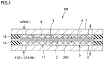
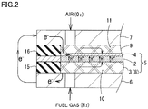
- Figs. 1 and 2 conceptually show a cell structure (fuel cell unit) 101 of a solid oxide fuel cell. It should be noted that, although Fig. 1 shows one cell structure, a fuel cell is generally composed by stacking a plurality of cell units in a thickness direction to increase a voltage for power generation.
- Fuel cell unit 101 includes a membrane electrode assembly 5 having a cathode layer 4 as an air electrode and an anode layer 3 as a fuel electrode, with a solid electrolyte layer 2 being sandwiched therebetween.
- Solid electrolyte layer 2 can be constituted of, for example, LSGM (lanthanum gallate), YSZ (Yttria Stabilized Zirconia), GDC (Gadolinium Doped Ceria), or the like.
- Cathode layer 4 in accordance with the present embodiment is formed by integrally firing a cathode material in a predetermined region on one side of solid electrolyte layer 2.
- anode layer 3 is provided by stacking a porous anode member 8 made of a metal porous body on the other side of solid electrolyte layer 2 to be pressed thereagainst.
- a current collecting member 7 On the outside of cathode layer 4 of membrane electrode assembly 5, a current collecting member 7 is provided, with a current collector 9 made of a metal porous body being interposed therebetween.
- Current collector 9 is constituted of a metal porous body having a high porosity, and serves as a gas flow channel 11.
- anode layer 3 of membrane electrode assembly 5 On the outside of anode layer 3 of membrane electrode assembly 5, a current collecting member 6 is provided to be directly stacked on anode layer 3.
- anode layer 3 is constituted of a metal porous body, and thereby serves as a gas flow channel 10 and also as a current collector.
- Current collector 9 and porous anode member 8 are constituted of porous bodies having electrical conductivity, and diffuse gases flowing through gas flow channels 10, 11 provided in these members to cathode layer 4 and solid electrolyte layer 2 to act thereon.
- Current collector 9 is configured to electrically connect cathode layer 4 and current collecting member 7 for electrical conduction therebetween.
- porous anode member 8 is configured to electrically connect solid electrolyte layer 2 and current collecting member 6 for electrical conduction therebetween.
- Fuel cell unit 101 is composed by stacking current collector 9, current collecting member 7, porous anode member 8, and current collecting member 6 on both sides of membrane electrode assembly 5, and sealing peripheral edge portions with gaskets 15, 16.
- Air containing oxygen as an oxidizer is introduced into gas flow channel 11, and oxygen is supplied to cathode layer 4 through current collector 9.
- a fuel gas containing hydrogen as a fuel is introduced into gas flow channel 10, and hydrogen is supplied to solid electrolyte layer 2 through porous anode member 8 which serves as anode layer 3.
- solid electrolyte layer 2 and cathode layer 4 are illustrated to be thicker than in reality for ease of understanding.
- Cathode layer 4 can be constituted of, for example, SSC (Sm 0.5 Sr 0. 5CoO 3 ), LSCF (Lanthanum Strontium Cobalt Ferrite), LSM (Lanthanum Strontium Manganate), BSCF (BaSrCoFe-based oxide), or the like.
- current collector 9 can be constituted of a variety of porous bodies having electrical conductivity.
- current collector 9 can also be constituted of the same metal porous body as that for porous anode member 8.
- Cathode layer 4 is an oxygen electrode, and its vicinity serves as a strong corrosive environment. Accordingly, cathode layer 4 and current collector 9 are preferably formed of materials having a high corrosion resistance.
- anode layer 3 is a fuel electrode, and its vicinity serves as a reducing atmosphere. Accordingly, porous anode member 8 is not required to be as corrosion resistant as cathode layer 4.
- anode layer 3 is composed by stacking porous anode member 8 made of a metal porous body on solid electrolyte layer 2 to be pressed thereagainst.
- solid electrolyte layer 2 and anode layer 3 are not integrally fired in the present embodiment, there occurs no reaction between constituent materials at a boundary surface between these layers during a firing step and the like, preventing an increase in electric resistance and a decrease in ionic conductivity.
- anode layer 3 can also serve as a current collector, the number of parts can also be reduced.
- anode layer 3 is stacked on solid electrolyte layer 2 to be pressed thereagainst. Therefore, even when there is a large difference in thermal expansion coefficient and the like between these members, there is no possibility that a crack or the like resulting from the thermal expansion coefficient and the like may occur as in the case of integral firing, and thus a high-quality fuel cell can be configured.
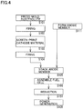
- a solid electrolyte material (LSGM: lanthanum gallate) was press-molded (S101 in Fig. 4 ) to form a plate-shaped solid electrolyte molded body, which was fired at 1500°C for 5 hours (S102 in Fig. 4 ) to form 300- ⁇ m-thick plate-shaped solid electrolyte layer 2.
- LSGM lanthanum gallate
- a cathode material (SSC: Sm 0.5 Sr 0.5 CoO 3 ) was applied onto the fired solid electrolyte molded body by screen printing (S103 in Fig. 4 ), and firing was performed thereon at 950°C for 0.5 hours (S104 in Fig. 4 ) to form 40- ⁇ m-thick cathode layer 4 integrally with solid electrolyte layer 2.
- Porous anode member 8 had a porosity of 96%, a thickness of 1 mm, and a basis weight of 400 g/m 2 .
- Fuel cell unit 101 was assembled by stacking current collecting member 7, current collector 9, solid electrolyte layer 2 provided with cathode layer 4, porous anode member 8, and current collecting member 6, and pressing porous anode member 8 against solid electrolyte layer 2 (S105 and S106 in Fig. 4 ). Porous anode member 8 was stacked on solid electrolyte layer 2 with its thickness being decreased by 5% due to a pressing force. Porous anode member 8 was stacked to be pressed in a state where plastic deformation occurred in the vicinity of interfaces with solid electrolyte layer 2 and current collecting member 6.
- Obtained fuel cell unit 101 was heated to 1000°C to be reduced (S107 in Fig. 4 ), and thereafter a performance test was conducted with each of hydrogen gas (H 2 100%) and air being introduced at 100 cc/min (S108 in Fig. 4 ).
- the fuel cell unit using a membrane electrode assembly in accordance with Example 1 was able to obtain an output of 206 mW/cm 2 .
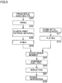
- Solid electrolyte layer 2 having the same configuration as that in Example 1 was formed by the same step as that in Example 1 (S201 to S202 in Fig. 5 ).
- Cathode layer 4 having the same configuration as that in Example 1 was formed by the same step as that in Example 1 (S203 to S204 in Fig. 5 ).
- a metal porous body having the same configuration as that in Example 1 was formed with the same technique as that in Example 1 (S211 in Fig. 5 ).
- This metal porous body was plated with 5- ⁇ m-thick Co-Ni plating to obtain porous anode member 8 (S212 in Fig. 5 ).
- the component composition of the above Co-Ni plating was set such that the mass ratio of the Co component to the Ni component was 3 to 1.
- porous anode member 8 As in Example 1, fuel cell unit 101 was assembled, with porous anode member 8 being pressed against solid electrolyte layer 2 (S205, S206 in Fig. 5 ). Porous anode member 8 was stacked on solid electrolyte layer 2 with its thickness being decreased by 5% due to a pressing force. As in Example 1, porous anode member 8 was stacked to be pressed in a state where plastic deformation occurred in the vicinity of interfaces with solid electrolyte layer 2 and current collecting member 6.
- Obtained fuel cell unit 101 was heated to 1000°C to be reduced (S207 in Fig. 5 ), and a performance test was conducted (S208 in Fig. 5 ). The performance test was conducted under the same conditions as those in Example 1.
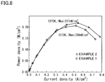
- Fig. 8 shows the fuel cell unit using a membrane electrode assembly in accordance with Example 2.
- Fig. 8 also shows the performance curve of the fuel cell unit using the membrane electrode assembly in accordance with Example 1.
- the output of the fuel cell unit using the membrane electrode assembly in accordance with Example 2 was higher than the output of the fuel cell unit using the membrane electrode assembly in accordance with Example 1 (206 mW/cm 2 ). This is considered to be because the Co-Ni plating increases electrical conductivity and improves the catalytic activity in porous anode member 8.
- Solid electrolyte layer 2 having the same configuration as that in Example 1 was formed by the same step as that in Example 1 (S201 to S202 in Fig. 5 ).
- Cathode layer 4 having the same configuration as that in Example 1 was formed by the same step as that in Example 1 (S203 to S204 in Fig. 5 ).
- a metal porous body having the same configuration as that in Example 1 was formed with the same technique as that in Example 1 (S211 in Fig. 5 ).
- This metal porous body was plated with 5- ⁇ m-thick Mn-Co plating to obtain porous anode member 8 (S212 in Fig. 5 ).
- the component composition of the above Mn-Co plating was set such that the mass ratio of the Mn component to the Co component was 9 to 1.
- porous anode member 8 As in Example 1, fuel cell unit 101 was assembled, with porous anode member 8 being pressed against solid electrolyte layer 2 (S205, S206 in Fig. 5 ). Porous anode member 8 was stacked on solid electrolyte layer 2 with its thickness being decreased by 5% due to a pressing force. As in Example 1, porous anode member 8 was stacked to be pressed in a state where plastic deformation occurred in the vicinity of interfaces with solid electrolyte layer 2 and current collecting member 6.
- Obtained fuel cell unit 101 was heated to 1000°C to be reduced (S207 in Fig. 5 ), and a performance test was conducted (S208 in Fig. 5 ). The performance test was conducted under the same conditions as those in Example 1.
- Fig. 9 shows the fuel cell unit using a membrane electrode assembly in accordance with Example 3.
- Fig. 9 also shows the performance curve of the fuel cell unit using the membrane electrode assembly in accordance with Example 1.
- the output of the fuel cell unit using the membrane electrode assembly in accordance with Example 3 was higher than the output of the fuel cell unit using the membrane electrode assembly in accordance with Example 1 (206 mW/cm 2 ). This is considered to be because the Mn-Co plating increases electrical conductivity and improves the catalytic activity in porous anode member 8.
- the output of the fuel cell unit using the membrane electrode assembly in accordance with Example 3 was higher than the output of the fuel cell unit in accordance with Example 2 shown in Fig. 8 . This is considered to be because the catalytic activity of the Mn-Co plating is higher than the catalytic activity of the Co-Ni plating.
- Solid electrolyte layer 2 having the same configuration as that in Example 1 was formed by the same step as that in Example 1 (S301 to S302 in Fig. 6 ).
- Cathode layer 4 having the same configuration as that in Example 1 was formed by the same step as that in Example 1 (S303 to S304 in Fig. 6 ).
- a metal porous body having the same configuration as that in Example 1 was formed with the same technique as that in Example 1 (S311 in Fig. 6 ).
- This metal porous body was filled with a catalyst made of NiO (S312 in Fig. 6 ).
- the catalyst had an average particle diameter of 1 ⁇ m, and the fill amount was set to 80 to 90 vol%.
- porous anode member 8 As in Example 1, fuel cell unit 101 was assembled, with porous anode member 8 being pressed against solid electrolyte layer 2 (S305, S306 in Fig. 6 ). Porous anode member 8 was stacked on solid electrolyte layer 2 with its thickness being decreased by 5% due to a pressing force. As in Example 1, porous anode member 8 was stacked to be pressed in a state where plastic deformation occurred in the vicinity of interfaces with solid electrolyte layer 2 and current collecting member 6.
- Obtained fuel cell unit 101 was heated to 1000°C to be reduced (S307 in Fig. 6 ), and a performance test was conducted (S308 in Fig. 6 ). The performance test was conducted under the same conditions as those in Example 1.
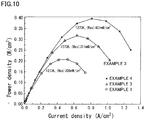
- Fig. 10 shows the fuel cell unit using a membrane electrode assembly in accordance with Example 4, and the performance curve of the fuel cell unit using the membrane electrode assembly in accordance with Example 3.
- the output of the fuel cell unit using the membrane electrode assembly in accordance with Example 4 was higher than the outputs of the fuel cell units using the membrane electrode assemblies in accordance with Examples 1 and 3 (206 mW/cm 2 and 311 mW/cm 2 , respectively). This is considered to be because the filled NiO is reduced during power generation and has a high activity as a catalyst.
Landscapes
- Chemical & Material Sciences (AREA)
- Chemical Kinetics & Catalysis (AREA)
- General Chemical & Material Sciences (AREA)
- Electrochemistry (AREA)
- Engineering & Computer Science (AREA)
- Manufacturing & Machinery (AREA)
- Sustainable Development (AREA)
- Sustainable Energy (AREA)
- Life Sciences & Earth Sciences (AREA)
- Materials Engineering (AREA)
- Composite Materials (AREA)
- Ceramic Engineering (AREA)
- Fuel Cell (AREA)
- Inert Electrodes (AREA)
Applications Claiming Priority (2)
| Application Number | Priority Date | Filing Date | Title |
|---|---|---|---|
| JP2014135917A JP6434723B2 (ja) | 2014-07-01 | 2014-07-01 | 膜電極複合体、膜電極複合体の製造方法、燃料電池及び燃料電池の製造方法 |
| PCT/JP2015/067990 WO2016002579A1 (ja) | 2014-07-01 | 2015-06-23 | 膜電極複合体、膜電極複合体の製造方法、燃料電池及び燃料電池の製造方法 |
Publications (3)
| Publication Number | Publication Date |
|---|---|
| EP3166166A1 true EP3166166A1 (de) | 2017-05-10 |
| EP3166166A4 EP3166166A4 (de) | 2017-11-22 |
| EP3166166B1 EP3166166B1 (de) | 2021-12-08 |
Family
ID=55019123
Family Applications (1)
| Application Number | Title | Priority Date | Filing Date |
|---|---|---|---|
| EP15814963.3A Active EP3166166B1 (de) | 2014-07-01 | 2015-06-23 | Filmelektrodenverbundstoff, verfahren zur herstellung eines filmelektrodenverbundstoffes, brennstoffzelle und verfahren zur herstellung einer brennstoffzelle |
Country Status (5)
| Country | Link |
|---|---|
| US (1) | US10431840B2 (de) |
| EP (1) | EP3166166B1 (de) |
| JP (1) | JP6434723B2 (de) |
| CN (1) | CN106575784B (de) |
| WO (1) | WO2016002579A1 (de) |
Families Citing this family (9)
| Publication number | Priority date | Publication date | Assignee | Title |
|---|---|---|---|---|
| JP6990236B2 (ja) * | 2017-04-24 | 2022-01-12 | 住友電気工業株式会社 | 酸化物分散金属多孔体、電解用電極および水素製造装置 |
| EP3812476B1 (de) | 2018-06-21 | 2023-04-12 | Sumitomo Electric Industries, Ltd. | Poröser körper, stromkollektor damit und brennstoffzelle |
| KR102750642B1 (ko) * | 2018-12-26 | 2025-01-06 | 현대자동차주식회사 | 막-전극 접합체의 제조 방법 및 그로부터 제조된 막-전극 접합체 |
| JP7355034B2 (ja) * | 2019-05-22 | 2023-10-03 | 住友電気工業株式会社 | 多孔体、それを含む燃料電池、およびそれを含む水蒸気電解装置 |
| CN113574207A (zh) * | 2019-08-21 | 2021-10-29 | 松下知识产权经营株式会社 | 压缩装置 |
| JP7279183B2 (ja) * | 2019-11-07 | 2023-05-22 | 株式会社日立ハイテク | 燃料電池セル、燃料電池システム、燃料電池セル製造方法 |
| JP7567810B2 (ja) * | 2019-12-24 | 2024-10-16 | 住友電気工業株式会社 | 多孔体、およびそれを含む燃料電池 |
| DE102020130693A1 (de) | 2020-11-20 | 2022-05-25 | Schaeffler Technologies AG & Co. KG | Bauteil für eine elektrochemische Zelle, sowie Redox-Flow-Zelle, Brennstoffzelle und Elektrolyseur |
| JP2022023997A (ja) * | 2021-11-05 | 2022-02-08 | 東京瓦斯株式会社 | 電気化学デバイス |
Family Cites Families (16)
| Publication number | Priority date | Publication date | Assignee | Title |
|---|---|---|---|---|
| JPH07245112A (ja) * | 1994-03-07 | 1995-09-19 | Fuji Electric Co Ltd | 固体電解質型燃料電池 |
| JP4383092B2 (ja) * | 2003-05-28 | 2009-12-16 | 京セラ株式会社 | 電気化学素子 |
| AU2004252862B2 (en) | 2003-06-09 | 2008-04-17 | Saint-Gobain Ceramics & Plastics, Inc. | Stack supported solid oxide fuel cell |
| US20070015015A1 (en) * | 2005-07-12 | 2007-01-18 | Koji Hoshino | Solid oxide fuel cell |
| US8026020B2 (en) * | 2007-05-08 | 2011-09-27 | Relion, Inc. | Proton exchange membrane fuel cell stack and fuel cell stack module |
| JP2009187887A (ja) * | 2008-02-08 | 2009-08-20 | Ngk Spark Plug Co Ltd | 燃料極集電体及び固体電解質形燃料電池 |
| JP5369050B2 (ja) * | 2010-05-20 | 2013-12-18 | 住友電気工業株式会社 | 高耐食性を有する金属多孔体 |
| JP5711927B2 (ja) | 2010-09-30 | 2015-05-07 | マグネクス株式会社 | 固体酸化物型燃料電池 |
| EP2650393A4 (de) * | 2010-12-08 | 2015-02-25 | Sumitomo Electric Industries | Metallischer poröser körper mit hoher korrosionsbeständigkeit und verfahren zu seiner herstellung |
| JP6080088B2 (ja) * | 2011-10-27 | 2017-02-15 | 住友電気工業株式会社 | 多孔質集電体及びこれを用いた燃料電池 |
| JP2012099497A (ja) | 2012-01-16 | 2012-05-24 | Ngk Spark Plug Co Ltd | 固体酸化物型燃料電池セル及び固体酸化物型燃料電池スタック |
| JP2013239321A (ja) * | 2012-05-15 | 2013-11-28 | Sumitomo Electric Ind Ltd | 固体電解質積層体、固体電解質積層体の製造方法及び燃料電池 |
| JP5935551B2 (ja) * | 2012-07-04 | 2016-06-15 | 住友電気工業株式会社 | 電解質複合部材の製造方法 |
| CN103594719B (zh) * | 2012-08-16 | 2016-01-20 | 中国科学院上海高等研究院 | 一种燃料电池 |
| WO2015137102A1 (ja) | 2014-03-12 | 2015-09-17 | 住友電気工業株式会社 | 多孔質集電体、燃料電池及び多孔質集電体の製造方法 |
| KR20160138053A (ko) | 2014-03-31 | 2016-12-02 | 스미토모덴키고교가부시키가이샤 | 다공질 집전체 및 연료 전지 |
-
2014
- 2014-07-01 JP JP2014135917A patent/JP6434723B2/ja active Active
-
2015
- 2015-06-23 WO PCT/JP2015/067990 patent/WO2016002579A1/ja not_active Ceased
- 2015-06-23 EP EP15814963.3A patent/EP3166166B1/de active Active
- 2015-06-23 CN CN201580035855.0A patent/CN106575784B/zh active Active
- 2015-06-23 US US15/322,537 patent/US10431840B2/en active Active
Also Published As
| Publication number | Publication date |
|---|---|
| WO2016002579A1 (ja) | 2016-01-07 |
| CN106575784A (zh) | 2017-04-19 |
| CN106575784B (zh) | 2019-05-31 |
| EP3166166A4 (de) | 2017-11-22 |
| US10431840B2 (en) | 2019-10-01 |
| EP3166166B1 (de) | 2021-12-08 |
| US20170133699A1 (en) | 2017-05-11 |
| JP6434723B2 (ja) | 2018-12-05 |
| JP2016015217A (ja) | 2016-01-28 |
Similar Documents
| Publication | Publication Date | Title |
|---|---|---|
| EP3166166B1 (de) | Filmelektrodenverbundstoff, verfahren zur herstellung eines filmelektrodenverbundstoffes, brennstoffzelle und verfahren zur herstellung einer brennstoffzelle | |
| EP3605694B1 (de) | Elektrochemisches element, elektrochemisches modul, elektrochemische vorrichtung, energiesystem, festoxid-brennstoffzelle und verfahren zur herstellung eines elektrochemischen elements | |
| CN108701843B (zh) | 固体氧化物型燃料电池 | |
| EP3352274A1 (de) | Metallträgerartiges elektrochemisches element und verfahren zur herstellung einer festoxidbrennstoffzelle und metallträgerartiges elektrochemisches element | |
| EP3324471B1 (de) | Brennstoffzelle | |
| US8697313B2 (en) | Method for making a fuel cell from a solid oxide monolithic framework | |
| US11767586B2 (en) | Manufacturing method for alloy material, alloy material, electrochemical element, electrochemical module, electrochemical device, energy system and solid oxide fuel cell | |
| JP6279519B2 (ja) | 燃料電池スタックおよび燃料電池単セル | |
| EP3300151B1 (de) | Festoxidbrennstoffzelle | |
| US8715886B1 (en) | Method for making a fuel cell | |
| JP6370696B2 (ja) | セル構造体、電解質膜−電極接合体、および、燃料電池 | |
| JP6773053B2 (ja) | 燃料電池 | |
| JP2018206693A (ja) | 導電性部材、電気化学反応単位、および、電気化学反応セルスタック | |
| EP3422448B1 (de) | Brennstoffzellenenergieerzeugungseinheit und brennstoffzellenstapel | |
| CN111244498A (zh) | 燃料电池和燃料电池堆 | |
| EP2083465A1 (de) | Verfahren zur Herstellung einer vollständig dichten, in eine Membran-Elektrolyt-Baugruppe einer Festoxid-Brennstoffzelle eingebettete Elektrolytschicht | |
| JP7349846B2 (ja) | 電気化学セル、電気化学反応セルスタック | |
| JP5667100B2 (ja) | 固体酸化物形燃料電池の製造方法 | |
| WO2018146809A1 (ja) | 電気化学セルスタック | |
| JP2022016758A (ja) | 固体酸化物形燃料電池 | |
| US10693154B2 (en) | Method for manufacturing fuel cell stack | |
| JP5732180B1 (ja) | 燃料電池 | |
| Yano et al. | Solid oxide fuel cell with anodes using proton conductor (Barium-Cerium/Yttrium oxide) | |
| JP2018147714A (ja) | 電気化学反応単セルおよび電気化学反応セルスタック | |
| Cable et al. | Method for Making a Fuel Cell from a Solid Oxide Monolithic Framework |
Legal Events
| Date | Code | Title | Description |
|---|---|---|---|
| STAA | Information on the status of an ep patent application or granted ep patent |
Free format text: STATUS: THE INTERNATIONAL PUBLICATION HAS BEEN MADE |
|
| PUAI | Public reference made under article 153(3) epc to a published international application that has entered the european phase |
Free format text: ORIGINAL CODE: 0009012 |
|
| STAA | Information on the status of an ep patent application or granted ep patent |
Free format text: STATUS: REQUEST FOR EXAMINATION WAS MADE |
|
| 17P | Request for examination filed |
Effective date: 20170112 |
|
| AK | Designated contracting states |
Kind code of ref document: A1 Designated state(s): AL AT BE BG CH CY CZ DE DK EE ES FI FR GB GR HR HU IE IS IT LI LT LU LV MC MK MT NL NO PL PT RO RS SE SI SK SM TR |
|
| AX | Request for extension of the european patent |
Extension state: BA ME |
|
| DAV | Request for validation of the european patent (deleted) | ||
| DAX | Request for extension of the european patent (deleted) | ||
| A4 | Supplementary search report drawn up and despatched |
Effective date: 20171025 |
|
| RIC1 | Information provided on ipc code assigned before grant |
Ipc: H01M 8/02 20160101ALI20171017BHEP Ipc: H01M 8/0232 20160101ALI20171017BHEP Ipc: H01M 8/0297 20160101ALI20171017BHEP Ipc: H01M 8/12 20160101ALI20171017BHEP Ipc: H01M 8/0245 20160101ALI20171017BHEP Ipc: H01M 8/0234 20160101ALN20171017BHEP Ipc: H01M 4/88 20060101ALI20171017BHEP Ipc: H01M 4/86 20060101AFI20171017BHEP Ipc: H01M 4/90 20060101ALI20171017BHEP Ipc: H01M 8/2432 20160101ALI20171017BHEP |
|
| RIC1 | Information provided on ipc code assigned before grant |
Ipc: H01M 4/86 20060101AFI20210628BHEP Ipc: H01M 4/88 20060101ALI20210628BHEP Ipc: H01M 8/02 20160101ALI20210628BHEP Ipc: H01M 8/12 20160101ALI20210628BHEP Ipc: H01M 8/0232 20160101ALI20210628BHEP Ipc: H01M 8/0245 20160101ALI20210628BHEP Ipc: H01M 8/2432 20160101ALI20210628BHEP Ipc: H01M 8/0297 20160101ALI20210628BHEP Ipc: H01M 4/90 20060101ALI20210628BHEP Ipc: H01M 8/0234 20160101ALN20210628BHEP |
|
| GRAP | Despatch of communication of intention to grant a patent |
Free format text: ORIGINAL CODE: EPIDOSNIGR1 |
|
| STAA | Information on the status of an ep patent application or granted ep patent |
Free format text: STATUS: GRANT OF PATENT IS INTENDED |
|
| INTG | Intention to grant announced |
Effective date: 20210818 |
|
| GRAS | Grant fee paid |
Free format text: ORIGINAL CODE: EPIDOSNIGR3 |
|
| GRAA | (expected) grant |
Free format text: ORIGINAL CODE: 0009210 |
|
| STAA | Information on the status of an ep patent application or granted ep patent |
Free format text: STATUS: THE PATENT HAS BEEN GRANTED |
|
| AK | Designated contracting states |
Kind code of ref document: B1 Designated state(s): AL AT BE BG CH CY CZ DE DK EE ES FI FR GB GR HR HU IE IS IT LI LT LU LV MC MK MT NL NO PL PT RO RS SE SI SK SM TR |
|
| REG | Reference to a national code |
Ref country code: GB Ref legal event code: FG4D |
|
| REG | Reference to a national code |
Ref country code: AT Ref legal event code: REF Ref document number: 1454433 Country of ref document: AT Kind code of ref document: T Effective date: 20211215 Ref country code: CH Ref legal event code: EP |
|
| REG | Reference to a national code |
Ref country code: DE Ref legal event code: R096 Ref document number: 602015075654 Country of ref document: DE |
|
| REG | Reference to a national code |
Ref country code: IE Ref legal event code: FG4D |
|
| REG | Reference to a national code |
Ref country code: LT Ref legal event code: MG9D |
|
| REG | Reference to a national code |
Ref country code: NL Ref legal event code: MP Effective date: 20211208 |
|
| PG25 | Lapsed in a contracting state [announced via postgrant information from national office to epo] |
Ref country code: RS Free format text: LAPSE BECAUSE OF FAILURE TO SUBMIT A TRANSLATION OF THE DESCRIPTION OR TO PAY THE FEE WITHIN THE PRESCRIBED TIME-LIMIT Effective date: 20211208 Ref country code: LT Free format text: LAPSE BECAUSE OF FAILURE TO SUBMIT A TRANSLATION OF THE DESCRIPTION OR TO PAY THE FEE WITHIN THE PRESCRIBED TIME-LIMIT Effective date: 20211208 Ref country code: FI Free format text: LAPSE BECAUSE OF FAILURE TO SUBMIT A TRANSLATION OF THE DESCRIPTION OR TO PAY THE FEE WITHIN THE PRESCRIBED TIME-LIMIT Effective date: 20211208 Ref country code: BG Free format text: LAPSE BECAUSE OF FAILURE TO SUBMIT A TRANSLATION OF THE DESCRIPTION OR TO PAY THE FEE WITHIN THE PRESCRIBED TIME-LIMIT Effective date: 20220308 |
|
| REG | Reference to a national code |
Ref country code: AT Ref legal event code: MK05 Ref document number: 1454433 Country of ref document: AT Kind code of ref document: T Effective date: 20211208 |
|
| PG25 | Lapsed in a contracting state [announced via postgrant information from national office to epo] |
Ref country code: SE Free format text: LAPSE BECAUSE OF FAILURE TO SUBMIT A TRANSLATION OF THE DESCRIPTION OR TO PAY THE FEE WITHIN THE PRESCRIBED TIME-LIMIT Effective date: 20211208 Ref country code: NO Free format text: LAPSE BECAUSE OF FAILURE TO SUBMIT A TRANSLATION OF THE DESCRIPTION OR TO PAY THE FEE WITHIN THE PRESCRIBED TIME-LIMIT Effective date: 20220308 Ref country code: LV Free format text: LAPSE BECAUSE OF FAILURE TO SUBMIT A TRANSLATION OF THE DESCRIPTION OR TO PAY THE FEE WITHIN THE PRESCRIBED TIME-LIMIT Effective date: 20211208 Ref country code: HR Free format text: LAPSE BECAUSE OF FAILURE TO SUBMIT A TRANSLATION OF THE DESCRIPTION OR TO PAY THE FEE WITHIN THE PRESCRIBED TIME-LIMIT Effective date: 20211208 Ref country code: GR Free format text: LAPSE BECAUSE OF FAILURE TO SUBMIT A TRANSLATION OF THE DESCRIPTION OR TO PAY THE FEE WITHIN THE PRESCRIBED TIME-LIMIT Effective date: 20220309 Ref country code: ES Free format text: LAPSE BECAUSE OF FAILURE TO SUBMIT A TRANSLATION OF THE DESCRIPTION OR TO PAY THE FEE WITHIN THE PRESCRIBED TIME-LIMIT Effective date: 20211208 |
|
| PG25 | Lapsed in a contracting state [announced via postgrant information from national office to epo] |
Ref country code: NL Free format text: LAPSE BECAUSE OF FAILURE TO SUBMIT A TRANSLATION OF THE DESCRIPTION OR TO PAY THE FEE WITHIN THE PRESCRIBED TIME-LIMIT Effective date: 20211208 |
|
| PG25 | Lapsed in a contracting state [announced via postgrant information from national office to epo] |
Ref country code: SM Free format text: LAPSE BECAUSE OF FAILURE TO SUBMIT A TRANSLATION OF THE DESCRIPTION OR TO PAY THE FEE WITHIN THE PRESCRIBED TIME-LIMIT Effective date: 20211208 Ref country code: SK Free format text: LAPSE BECAUSE OF FAILURE TO SUBMIT A TRANSLATION OF THE DESCRIPTION OR TO PAY THE FEE WITHIN THE PRESCRIBED TIME-LIMIT Effective date: 20211208 Ref country code: RO Free format text: LAPSE BECAUSE OF FAILURE TO SUBMIT A TRANSLATION OF THE DESCRIPTION OR TO PAY THE FEE WITHIN THE PRESCRIBED TIME-LIMIT Effective date: 20211208 Ref country code: PT Free format text: LAPSE BECAUSE OF FAILURE TO SUBMIT A TRANSLATION OF THE DESCRIPTION OR TO PAY THE FEE WITHIN THE PRESCRIBED TIME-LIMIT Effective date: 20220408 Ref country code: EE Free format text: LAPSE BECAUSE OF FAILURE TO SUBMIT A TRANSLATION OF THE DESCRIPTION OR TO PAY THE FEE WITHIN THE PRESCRIBED TIME-LIMIT Effective date: 20211208 Ref country code: CZ Free format text: LAPSE BECAUSE OF FAILURE TO SUBMIT A TRANSLATION OF THE DESCRIPTION OR TO PAY THE FEE WITHIN THE PRESCRIBED TIME-LIMIT Effective date: 20211208 |
|
| PG25 | Lapsed in a contracting state [announced via postgrant information from national office to epo] |
Ref country code: PL Free format text: LAPSE BECAUSE OF FAILURE TO SUBMIT A TRANSLATION OF THE DESCRIPTION OR TO PAY THE FEE WITHIN THE PRESCRIBED TIME-LIMIT Effective date: 20211208 Ref country code: AT Free format text: LAPSE BECAUSE OF FAILURE TO SUBMIT A TRANSLATION OF THE DESCRIPTION OR TO PAY THE FEE WITHIN THE PRESCRIBED TIME-LIMIT Effective date: 20211208 |
|
| REG | Reference to a national code |
Ref country code: DE Ref legal event code: R097 Ref document number: 602015075654 Country of ref document: DE |
|
| PG25 | Lapsed in a contracting state [announced via postgrant information from national office to epo] |
Ref country code: IS Free format text: LAPSE BECAUSE OF FAILURE TO SUBMIT A TRANSLATION OF THE DESCRIPTION OR TO PAY THE FEE WITHIN THE PRESCRIBED TIME-LIMIT Effective date: 20220408 |
|
| PLBE | No opposition filed within time limit |
Free format text: ORIGINAL CODE: 0009261 |
|
| STAA | Information on the status of an ep patent application or granted ep patent |
Free format text: STATUS: NO OPPOSITION FILED WITHIN TIME LIMIT |
|
| PG25 | Lapsed in a contracting state [announced via postgrant information from national office to epo] |
Ref country code: DK Free format text: LAPSE BECAUSE OF FAILURE TO SUBMIT A TRANSLATION OF THE DESCRIPTION OR TO PAY THE FEE WITHIN THE PRESCRIBED TIME-LIMIT Effective date: 20211208 Ref country code: AL Free format text: LAPSE BECAUSE OF FAILURE TO SUBMIT A TRANSLATION OF THE DESCRIPTION OR TO PAY THE FEE WITHIN THE PRESCRIBED TIME-LIMIT Effective date: 20211208 |
|
| 26N | No opposition filed |
Effective date: 20220909 |
|
| PG25 | Lapsed in a contracting state [announced via postgrant information from national office to epo] |
Ref country code: SI Free format text: LAPSE BECAUSE OF FAILURE TO SUBMIT A TRANSLATION OF THE DESCRIPTION OR TO PAY THE FEE WITHIN THE PRESCRIBED TIME-LIMIT Effective date: 20211208 |
|
| PG25 | Lapsed in a contracting state [announced via postgrant information from national office to epo] |
Ref country code: MC Free format text: LAPSE BECAUSE OF FAILURE TO SUBMIT A TRANSLATION OF THE DESCRIPTION OR TO PAY THE FEE WITHIN THE PRESCRIBED TIME-LIMIT Effective date: 20211208 |
|
| REG | Reference to a national code |
Ref country code: CH Ref legal event code: PL |
|
| REG | Reference to a national code |
Ref country code: BE Ref legal event code: MM Effective date: 20220630 |
|
| GBPC | Gb: european patent ceased through non-payment of renewal fee |
Effective date: 20220623 |
|
| PG25 | Lapsed in a contracting state [announced via postgrant information from national office to epo] |
Ref country code: LU Free format text: LAPSE BECAUSE OF NON-PAYMENT OF DUE FEES Effective date: 20220623 Ref country code: LI Free format text: LAPSE BECAUSE OF NON-PAYMENT OF DUE FEES Effective date: 20220630 Ref country code: IE Free format text: LAPSE BECAUSE OF NON-PAYMENT OF DUE FEES Effective date: 20220623 Ref country code: FR Free format text: LAPSE BECAUSE OF NON-PAYMENT OF DUE FEES Effective date: 20220630 Ref country code: CH Free format text: LAPSE BECAUSE OF NON-PAYMENT OF DUE FEES Effective date: 20220630 |
|
| PG25 | Lapsed in a contracting state [announced via postgrant information from national office to epo] |
Ref country code: IT Free format text: LAPSE BECAUSE OF FAILURE TO SUBMIT A TRANSLATION OF THE DESCRIPTION OR TO PAY THE FEE WITHIN THE PRESCRIBED TIME-LIMIT Effective date: 20211208 Ref country code: GB Free format text: LAPSE BECAUSE OF NON-PAYMENT OF DUE FEES Effective date: 20220623 Ref country code: BE Free format text: LAPSE BECAUSE OF NON-PAYMENT OF DUE FEES Effective date: 20220630 |
|
| P01 | Opt-out of the competence of the unified patent court (upc) registered |
Effective date: 20230515 |
|
| PG25 | Lapsed in a contracting state [announced via postgrant information from national office to epo] |
Ref country code: HU Free format text: LAPSE BECAUSE OF FAILURE TO SUBMIT A TRANSLATION OF THE DESCRIPTION OR TO PAY THE FEE WITHIN THE PRESCRIBED TIME-LIMIT; INVALID AB INITIO Effective date: 20150623 |
|
| PG25 | Lapsed in a contracting state [announced via postgrant information from national office to epo] |
Ref country code: MK Free format text: LAPSE BECAUSE OF FAILURE TO SUBMIT A TRANSLATION OF THE DESCRIPTION OR TO PAY THE FEE WITHIN THE PRESCRIBED TIME-LIMIT Effective date: 20211208 Ref country code: CY Free format text: LAPSE BECAUSE OF FAILURE TO SUBMIT A TRANSLATION OF THE DESCRIPTION OR TO PAY THE FEE WITHIN THE PRESCRIBED TIME-LIMIT Effective date: 20211208 |
|
| PG25 | Lapsed in a contracting state [announced via postgrant information from national office to epo] |
Ref country code: MT Free format text: LAPSE BECAUSE OF FAILURE TO SUBMIT A TRANSLATION OF THE DESCRIPTION OR TO PAY THE FEE WITHIN THE PRESCRIBED TIME-LIMIT Effective date: 20211208 |
|
| PGFP | Annual fee paid to national office [announced via postgrant information from national office to epo] |
Ref country code: DE Payment date: 20250429 Year of fee payment: 11 |
|
| PG25 | Lapsed in a contracting state [announced via postgrant information from national office to epo] |
Ref country code: TR Free format text: LAPSE BECAUSE OF FAILURE TO SUBMIT A TRANSLATION OF THE DESCRIPTION OR TO PAY THE FEE WITHIN THE PRESCRIBED TIME-LIMIT Effective date: 20211208 |